Image effects, also known as post-processing effects, are a feature of many rendering systems that lets you take an image that has been rendered by the camera and perform extra processing steps to modify the appearance of the image. For example, you can modify the colors of the image or overlay new elements onto the image with post-processing. In this chapter, we will see how post-processing can be used in each pipeline to enhance the look of your game.
Render Textures
Render texture is the term we use for any texture that has been rendered by the camera, as opposed to traditional textures that are usually created in an external program. Typically, a render texture is the same size as the screen or window the game is running in, although it is possible to downsample a render texture so that it has a lower resolution and takes up less texture memory. Let’s see how render textures work in Unity.
By default, Unity renders what each camera can see to the screen. However, cameras (including the main camera) can render to a texture instead, hence the term render texture. Broadly, there are two ways to do this: in the Editor and programmatically. To assign a target texture in the Editor, select your camera and drag a render texture onto the Output Texture slot on the Camera component (each pipeline styles the Camera component’s variables slightly different, so what you see might not exactly match Figure 11-1).
A screenshot of a camera dialog box lists base under render type, with output texture as new render texture, and target eye as both.
Figure 11-1
A camera with a render texture assigned to its Output Texture slot. This component looks different between each pipeline
Of course, we must get that texture somewhere. In the Project View, you can right-click and select Create ➤ Render Texture to create a new render texture asset. An example of such an asset can be seen in Figure 11-2. This asset can be attached to the Output Texture slot on your cameras, and it can be used as a texture on any material. At runtime, when the camera updates the texture, the material will update to reflect those changes.
A screenshot of the inspector window lists dimension, size, and color format under the new render texture, with a preview of the output.
Figure 11-2
A new render texture that has been assigned to the main camera. The preview at the bottom shows the camera’s output
There are a few settings you can change on the render texture, such as the format, which controls how many bits are used for each color channel, and the resolution. Play around with these options to see what happens. We can also create render textures at runtime and then assign those textures to cameras and materials. The following script provides simple usage examples.
using UnityEngine;
public class RTExample : MonoBehaviour
{
public Camera exampleCamera;
public Material exampleMaterial;
private RenderTexture rt;
private void Start()
{
rt = new RenderTexture(1920, 1080, 32, RenderTextureFormat.ARGB32);
rt.Create();
exampleCamera.targetTexture = rt;
exampleMaterial.SetTexture("_MainTex", rt);
}
}
Listing 11-1
Creating and using render textures with code
In Start, the RenderTexture constructor is used to set up the format of the texture. This method can take many sets of parameters, but I’ve used one of the most important combinations here. The first two values are the width and height of the texture in pixels, respectively. Next is the number of bits in the depth buffer – 32 gives us a full-precision depth buffer with stencil support. The last parameter is the format. I’ve used ARGB32, which gives us 8 bits per channel including alpha, which is the default on most platforms if no value is supplied.
The constructor doesn’t create any texture resource on the GPU by itself, so we must call the Create method on our texture to assign resources. Then, by setting the render texture to a camera’s targetTexture variable, we can make that camera render into the texture rather than onto the screen. Likewise, we can assign the texture to any texture property on a material, and the material will update accordingly.
This is all useful, but what does it have to do with post-processing effects? In the background, Unity uses render textures to handle the state of the frame buffer during a frame before outputting the resulting image to the screen. At certain points in the rendering loop, which differ between render pipelines, Unity exposes the screen texture and lets us modify its contents. This is where image effect shaders come in! An image effect shader takes the screen texture as an input and modifies the colors within, returning a new color value. The modified texture is put back into the rendering loop before being output to the screen. Let’s see how post-processing effects work in practice.
Post-Processing Effects
Post-processing effects in Unity come in two parts: the C# scripting side, which handles the render textures we are using and the materials we’re applying to those render textures, and the shader side, which controls how the contents of a render texture are modified. We can use any shader syntax we’re familiar with inside these shaders, but they should all sample the texture provided to them and modify the color of the texture in some way.
Note
Technically speaking, the shader isn’t necessarily forced to read the source texture and modify it, but it would rather defeat the point of it being a post-processing effect if it didn’t!
Post-processing effects work by supplying a quad mesh to the shader. This mesh has corners that line up exactly with the corners of the screen, and it has UV coordinates that exactly cover the [0,1] range in both axes. The vertex shader for a post-processing effect is very basic, as it just needs to position the quad mesh in the correct place and pass the UVs to the fragment shader. We also supply a render texture to the shader, called the source texture, which should be read and modified in some way inside the fragment shader. As a result, the fragment shader is where our focus will lie for post-processing effects.
Post-processing in Unity is a strange beast, as the level of support across the different render pipelines differs wildly:
The built-in render pipeline supports post-processing fully.
There is no official support for post-processing in URP, but we will see a workaround that lets us implement them with some effort. The shader side in URP is not much more complicated than the equivalent built-in pipeline shader.
HDRP provides support for writing custom post-processing shaders, which is one of the few circumstances where custom code shaders in HDRP are encouraged.
Shader Graph regrettably doesn’t provide official support for post-processing shaders.
Important Note
Although it’s technically feasible to put together some types of post-processing shader in Shader Graph, the lack of official support makes some common post-processing shader operations a lot more difficult to pull off, such as sampling multiple screen pixels in a loop. At that point, you lose the ease-of-use benefits that Shader Graph brings, and it stops being worth forcing it outside its capabilities. Therefore, we will not cover Shader Graph in this chapter.
It's a bit of a mess, but it’s a mess we can navigate! As a starting point, let’s create a post-processing effect that turns the screen grayscale based on the luminance of each color. This effect won’t be very complicated on the shader side, but it will illuminate the significant difference in complexity between the pipelines on the C# programming side.
Grayscale Image Effect
The grayscale image effect is simple – it takes the color of each pixel in the image, and based on the luminance of the color, it outputs a grayscale value that is then displayed on-screen. The human eye is most sensitive to green light and least sensitive to blue light, so the calculation we’ll use to obtain the grayscale luminance value is a dot product that looks like this:
Equation 11-1: Theluminance equation
Although they look like magic numbers plucked from thin air, these are real-world values representing the relative sensitivity of your eyes to each color channel, which sum to 1. A fully white input results in a fully white output, and the same is true for black inputs and outputs. Figure 11-3 shows a scene before and after the Grayscale effect is applied (if you’re viewing in black and white, both will look identical).
A hexad of bumpy circles of different colors involves the greyscale effect, and the output on the right has greyscale colored circles.
Figure 11-3
Grayscale effect before (left) and after (right) being applied
Now that we know how the grayscale calculation works, let’s see how post-processing effects are made in each pipeline, starting with the built-in render pipeline.
Post-Processing in the Built-In Pipeline
As I mentioned, writing post-processing shaders comes in two distinct parts: the scripting side and the shader side. First, let’s write the C# code that will be used to apply the shader effect to the screen.
Grayscale C# Scripting in the Built-In Pipeline
Create a new C# script by right-clicking in the Project View and selecting Create ➤ C# Script. We’ll name it “GrayscaleEffect.cs”. We can remove the boilerplate Update method and some of the using statements to be left with the following starting code.
using UnityEngine;
public class Grayscale : MonoBehaviour
{
void Start() { }
}
Listing 11-2
GrayscaleEffect code skeleton
In the built-in pipeline, we can include a method called OnRenderImage, which automatically gets called on any script that is attached to a GameObject that has a Camera component attached. This method takes two RenderTexture parameters: the source texture, which contains the state of the screen after the camera has finished rendering objects and is one that we will send to the shader for modification, and the destination texture, which is the one that will be shown on-screen.
Inside OnRenderImage, we need to write code that will send the source texture to the shader, retrieve the result, and send it to the destination texture. We can do that with the Graphics.Blit method. Graphics.Blit takes any two textures as arguments and copies the first texture onto the second texture, with the option of supplying a material. If we call Graphics.Blit with only the source and destination textures as arguments, then we won’t see any changes on-screen.
In this case, all we’re doing is copying the screen contents onto the screen. Although this obviously isn’t the behavior we want, this method is useful if we want to copy one render texture onto another in any other context. For the Grayscale effect, we’re going to supply a material. In the script, we can create the material in the Start method and hold a reference to it and then modify the Graphics.Blit call to include the material. To create the material, we’ll use Shader.Find, which lets us reference a shader by the name string we specify at the top of the shader file. We haven’t created the shader file yet, but I’m going to use the name “Examples/ImageEffect/Grayscale”, so we’ll use that.
Material mat;
void Start()
{
mat = new Material(Shader.Find("Examples/ImageEffect /Grayscale"));
}
Listing 11-4
Referencing a shader by name with Shader.Find
Caution
When using Shader.Find, be careful to make sure that the shader file you are referencing gets included in the final build. If a shader is used on a material in the project folder that is referenced in a scene, you’re fine. Otherwise, if it is only ever referenced programmatically, make sure it is included in Edit ➤ Project Settings ➤ Graphics tab in the Always Included Shaders list. Unity also includes any assets in the game build if they’re placed inside a folder named “Resources,” no matter whether it is a subfolder or whether you have multiple folders called “Resources.”
Now we can modify the Graphics.Blit method to use the material.
Graphics.Blit(src, dst, mat);
Listing 11-5
Using a material with Graphics.Blit
That’s all we need to do for the script in the built-in pipeline. Now that we’ve completed it, let’s move on to the shader file.
Grayscale Shader in the Built-In Pipeline
Unity provides a template file for image effects in the built-in render pipeline if you right-click in the Project View and select Create ➤ Shader ➤ Image Effect Shader. However, it will be useful to start from scratch to see which parts are important for an image effect shader. With that in mind, create a new shader file using that template, name the file “Grayscale.shader”, and delete the contents of the file. From there, we can build up each part of the shader. First, rename the shader on the first line to match the name we used in the script.
Shader "Examples/ImageEffect/Grayscale"
{
}
Listing 11-6
Renaming the Grayscale shader
Next, we need to include the source texture as a property. The Graphics.Blit method copies the texture to the _MainTex property if one exists, so that’s the name we’ll use inside the shader. We don’t need to include additional properties in this shader, although it is possible to include more in other image effect shaders if you need them.
{
Properties
{
_MainTex ("Texture", 2D) = "white" {}
}
}
Listing 11-7
Properties block for the Grayscale shader
Now we come to the SubShader. Inside the SubShader, we only need a single Pass block that contains the body of the shader. It’s not too important to include a Tags block to specify the render queue, because this shader won’t execute within the usual rendering loop anyway – it is executed specifically when the camera finished rendering everything on the screen. The Pass contains the HLSLPROGRAMblock.
Properties { ... }
SubShader
{
Pass
{
HLSLPROGRAM
...
ENDHLSL
}
}
Listing 11-8
Structure of the rest of the shader
Let’s go through the contents of the HLSLPROGRAM block from top to bottom. First, we need #pragma statements to specify which functions we’re using for the vertex and fragment shaders. After that, we’ll #include the UnityCG.cginc file, which contains useful functions and macros.
#pragma vertex vert
#pragma fragment frag
#include "UnityCG.cginc"
Listing 11-9
Setup for the HLSL block
Next, let’s add the appdata and v2f structs. The vertex shader needs to be passed the object-space position of the vertices of the screen quad that I mentioned, plus the UVs attached to it. The fragment shader only requires the clip-space position of each fragment and the associated UVs. As a result, both these structs are very basic.
struct appdata
{
float4 positionOS : POSITION;
float2 uv : TEXCOORD0;
};
struct v2f
{
float2 uv : TEXCOORD0;
float4 positionCS : SV_POSITION;
};
Listing 11-10
appdata and v2f structs
The vert function is also very short. We need to transform the vertex positions from object space to clip space using UnityObjectToClipPos. Then we can pass the UVs to the fragment shader without modification. Ordinarily, we might use TRANSFORM_TEX to apply scaling and offset to the UVs, but the _MainTex will never be scaled or offset, so there is no point.
Next, let’s declare _MainTex in HLSL. We have declared it in the Properties block in ShaderLab, but like all properties, we’ll need to define it again in HLSL. I’ll declare it between the vert and frag functions.
sampler2D _MainTex;
Listing 11-12
Declaring _MainTex in HLSL
Finally, we come to the fragment shader, which is the most important part of any post-processing effect. Here is where we sample the source texture and apply modifications to the colors within. The Grayscale shader is just a simple mapping from one set of colors to another, which requires passing the texture sample into a function that calculates the luminance of the color. Thankfully, UnityCG.cginc includes a function called Luminance, which converts an RGB color into a single grayscale float value based on the relative sensitivity of the human eye to red, green, and blue colors.
float4 frag (v2f i) : SV_Target
{
float4 textureSample = tex2D(_MainTex, i.uv);
float3 outputColor = Luminance(textureSample);
return float4(outputColor, 1.0f);
}
Listing 11-13
The fragment shader for the grayscale effect in the built-in pipeline
With that, the shader is complete. If we attach the GrayscaleEffect script to the main camera (or any GameObject with a Camera component attached), then the output from the camera will have the Grayscale effect applied, as in Figure 11-3. Now that we have seen how this works in the built-in pipeline, let’s look at how to make a post-processing effect in URP.
Post-Processing in URP
Unity does not yet officially support custom post-processing effects in URP. By that, I mean that there is no official template file or documentation for creating post-processing effects, as of Unity 2021.3. However, we can use the Renderer Features system to create them. Fair warning, though: The process is a lot more involved in URP than in the other pipelines. Hopefully, if you’re reading this book in the far future, there will be an official (and simpler) way to create URP effects!
One powerful feature of URP is the volume system, which lets developers apply an effect or list of effects that we bundle together into profiles. We can create global volumes, which apply the effect regardless of where the camera is, or local volumes, which apply the effect only when the camera is positioned within a specific trigger volume in 3D space. We will write code that is compatible with the URP volume system.
Grayscale C# Scripting in URP
We need to write code to control how URP applies the Grayscale shader to the screen – this is where URP requires a lot more work than the built-in render pipeline. In URP, the OnRenderImage method doesn’t get called at all, and we must use Renderer Features instead. At the end of Chapter 7, we saw how Renderer Features can be used in URP – this time, we will write our own custom Renderer Feature. The process to create a custom Renderer Feature for a post-processing effect is complicated, so let’s set out the steps required to create one:
We must create a class that holds the settings for the shader effect called GrayscaleSettings.
This class will inherit VolumeComponent and IPostProcessComponent, which allows our post-process to integrate with Unity’s volume system.
The settings that we define in this class will be visible on the Renderer Feature when we attach it to the features list on the Forward Renderer asset.
We must create a second class that drives the effect called GrayscaleRenderPass.
This class inherits from ScriptableRenderPass, the base class for passes, and it is responsible for setting up the post-process effect’s behavior and injecting the pass into the rendering loop.
We must create a third class that creates and sets up the pass called GrayscaleFeature.
This class will inherit from ScriptableRendererFeature, the base class for all features. It is responsible for creating render passes for the post-process.
Finally, we must write a shader file for the post-processing effect.
This workflow may seem complicated, but if we break each step down, you’ll see that each part has its purpose. To start, let’s create the settings script.
The GrayscaleSettings C# Script
Create a new C# script by right-clicking in the Project View and selecting Create ➤ C# Script, and name it “GrayscaleSettings.cs”. As I briefly described before, the purpose of this file is to hold all the settings required to make our post-process work. Some shader effects will have more settings than others, but our Grayscale effect is relatively minimal. First, replace the contents of the file with the following skeleton.
using UnityEngine;
using UnityEngine.Rendering;
using UnityEngine.Rendering.Universal;
public sealed class GrayscaleSettings : VolumeComponent, IPostProcessComponent
{
public bool IsActive() { }
public bool IsTileCompatible() { }
}
Listing 11-14
GrayscaleSettings code skeleton
Now let’s break down what’s happening here:
The script needs to use the UnityEngine.Rendering and UnityEngine.Rendering.Universal namespaces to be able to use URP’s volume system.
Inheriting from the VolumeComponent class is what allows us to plug into the URP volume system.
The IPostProcessComponent interface is what makes GrayscaleSettings work as settings for a post-processing effect specifically. We are required to define the IsActive and IsTileCompatible methods from this interface.
When we want to add any post-processing effect to a volume profile, Unity will bring up a context menu to do so. We must add an attribute called VolumeComponentMenu to our class to define what name Unity will use for our effect in this menu. We also need to make the class serializable so that Unity can properly list the settings in the Inspector, which we can do with the System.Serializable attribute. Let’s add those to the class now.
public sealed class GrayscaleSettings : VolumeComponent, IPostProcessComponent { ... }
Listing 11-15
Adding attributes to the GrayscaleSettings class
Next, let’s add the setting variables required for this effect to work. Generally, these settings will match up with those used in the shader, with the exception of the _MainTex texture, which is supplied in the second C# script that we will write. In the case of our Grayscale effect, we’ll only include one setting: the strength of the effect, which is a float between 0 and 1. We use special types for these settings, such as the following:
FloatParameter – A single float that can take any value
ClampedFloatParameter – A single float that can take a value between defined minimum and maximum values
IntParameter – A single integer that can take any value
ClampedIntParameter – A single integer that can take a value between defined minimum and maximum values
TextureParameter – Any object that inherits the Texture base class, typically Texture2D or RenderTexture
Since the strength value should be bound between 0 and 1, let’s use ClampedFloatParameter for it. It takes three parameters: the first is the default value when we first attach the setting to a volume, the second is the minimum value it can take, and the third is the maximum value it can take. I like to add tooltips to each setting variable to provide more context to end users about what this variable is for, which we can do with the Tooltip attribute. Remember: other people might be using these effects other than you! These variables can be defined just above the two methods.
[Tooltip("How strongly the effect is applied. " +
"0 = original image, 1 = fully grayscale.")]
public ClampedFloatParameter strength = new ClampedFloatParameter(0.0f, 0.0f, 1.0f);
public bool IsActive() { ... }
Listing 11-16
Setting variables for the Grayscale effect
Note
It’s best practice to set up these effects so that the default values mean the effect is not active. If you don’t, the volume system may not work properly, and your effect might be applied globally all the time, even if you don’t have any volumes in the scene that use the effect.
Next, let’s handle IsActive. We will use this method in the second C# script we’ll write to decide whether to run the effect or not. We can define what “active” means for each effect – for the Grayscale effect, the strength should be higher than zero. On top of this, Unity will add a tick box onto every effect that lets us turn them on and off, even if they have no settings. For this, the VolumeComponent class (which we are inheriting from) exposes a variable called active.
public bool IsActive() => strength.value > 0.0f && active;
Listing 11-17
The IsActive method for the grayscale effect in URP
Finally, we’ll handle the IsTileCompatible method. The Unity documentation doesn’t provide any information on what this method does, so we will just make the method return false.
public bool IsTileCompatible() => false;
Listing 11-18
The IsTileCompatible method
The GrayscaleSettings script is now complete, so we can move on to the GrayscaleRenderPass script.
The GrayscaleRenderPass C# Script
This is the longest script we’ll need to write to get the Grayscale effect working in URP. Create a new C# script via Create ➤ C# Script and name it “GrayscaleRenderPass”. This script is going to control how URP interfaces between the shader, the settings we just created, and the renderer. This is effectively the “brain” of the post-process where we can customize exactly how it operates. Although a grayscale shader is one of the simplest post-processing effects we could create, this script still has many moving parts.
The GrayscaleRenderPass class inherits from ScriptableRenderPass, which is the base class for all render passes. We will need to override three methods from ScriptableRenderPass: namely, the Configure, Execute, and FrameCleanup methods. We will also supply a method called Setup. Here’s the code skeleton for this class.
using UnityEngine;
using UnityEngine.Rendering;
using UnityEngine.Rendering.Universal;
class GrayscaleRenderPass : ScriptableRenderPass
{
public void Setup(...) { ... }
public override void Configure(...){ ... }
public override void Execute(...){ ... }
public override void FrameCleanup(...){ ... }
}
Listing 11-19
The GrayscaleRenderPass skeleton
Before we fill out these methods with code, let’s add a few member variables, which we will place above all these methods. The pass needs to hold references to a few things:
The material that will use the Grayscale shader
A GrayscaleSettings object
The source render texture supplied by the camera
A temporary texture that we will use for applying the shader to the source texture
A profiler tag that we can use to profile how many system resources the post-processing effect takes up
We will include each of these variables at the top of the class.
private Material material;
private GrayscaleSettings settings;
private RenderTargetIdentifier source;
private RenderTargetIdentifier mainTex;
private string profilerTag;
public void Setup(...){ ... }
Listing 11-20
GrayscaleRenderPass instance variables
Next, let’s fill in each method in turn, starting with Setup. This method will be used to set up most of the member variables and attach this pass to the renderer. It takes a ScriptableRenderer and a profiler tag string as its two arguments.
public void Setup(ScriptableRenderer renderer, string profilerTag)
material = new Material(Shader.Find("Examples/ImageEffects/Grayscale"));
}
}
Listing 11-21
The Setup method for the grayscale effect in URP
The ScriptableRenderer is the object that controls rendering in URP. The cameraColorTarget member of a ScriptableRenderer is the color texture, which is the one we want to apply the Grayscale shader to. URP exposes several “events” throughout the rendering loop that we can attach our effects to; although the name doesn’t necessarily suggest so, the one we want is BeforeRenderingPostProcessing, which runs just before any post-processing included in URP that you have active. Finally, we must check if the effect is active, and if it is, we can create the material that will drive the effect and attach the pass to the renderer.
Next up is the Configure method, which we use to set up any temporary textures that will be used for the effect. Unlike the built-in pipeline, which exposes handles to two textures, source and destination, URP only gave us a single handle to the source texture. Later in the Execute method, we must read from this texture and write back to it, but calling Blit when both texture arguments are the same texture may result in undefined behavior, so we’ll create an intermediate texture and perform two Blit operations.
public override void Configure(CommandBuffer cmd, RenderTextureDescriptor cameraTextureDescriptor)
{
if (settings == null) return;
int id = Shader.PropertyToID("_MainTex");
mainTex = new RenderTargetIdentifier(id);
cmd.GetTemporaryRT(id, cameraTextureDescriptor);
base.Configure(cmd, cameraTextureDescriptor);
}
Listing 11-22
The Configure method for the grayscale effect in URP
The Execute method, which runs the effect, comes next. Inside this method, we create a CommandBuffer, which is an object that holds a list of rendering commands and attach commands to Blit the source and mainTex textures. Here’s what this method does:
First, we’ll create the command buffer by supplying the profiler tag so that we can use the Profiler window to evaluate the performance of the shader.
Next, we’ll Blit the source texture onto the mainTex texture, which just copies it since we’re not supplying a material. This step is important because we’re unable to Blit between the source texture and itself.
Then, we’ll set up any material properties. For the Grayscale effect, we only have one property to worry about: _Strength.
Next comes the all-important Blit in which we apply the material to mainTex and assign the results back to the source texture.
Finally, we can execute the command buffer and clean up its resources.
The Executemethod is run once per frame. If your post-processing effect had several properties or even multiple passes, then your command buffer could have many more commands attached to it.
public override void Execute(ScriptableRenderContext context, ref RenderingData renderingData)
The Execute method for the grayscale effect in URP
Finally, we come to the FrameCleanup method, which runs at the end of each frame to clean up any temporary data that was created back in Configure. In the case of our Grayscale effect, that means the mainTex texture.
public override void FrameCleanup(CommandBuffer cmd)
The FrameCleanup method for the grayscale effect in URP
The GrayscaleFeature C# Script
The final part of the puzzle is the Renderer Feature script, which will allow URP to run the effect in the first place. Start by creating a new C# script via Create ➤ C# Script, and name it “GrayscaleFeature.cs”. The GrayscaleFeature class will inherit from ScriptableRendererFeature, which requires us to override two abstract methods called Create and AddRenderPass. Here’s the code skeleton for the class.
using UnityEngine.Rendering.Universal;
public class GrayscaleFeature : ScriptableRendererFeature
{
GrayscaleRenderPass pass;
public override void Create() { ... }
public override void AddRenderPasses(...) { ... }
}
Listing 11-25
The GrayscaleFeature code skeleton
The first thing to note is that we’re including a variable called pass to hold our GrayscaleRenderPass. The Create method is called when GrayscaleFeature is first created, as the name suggests. Inside this method, we should create any render passes that the feature will use. We can also provide a name for the feature, which will be displayed when GrayscaleFeature is attached to the list of features on your Forward Renderer asset (we’ll attach it when the script is complete). The name variable is a member of ScriptableRendererFeature, so we don’t need to define it at the top of this class alongside pass.
public override void Create()
{
name = "Grayscale";
pass = new GrayscaleRenderPass();
}
Listing 11-26
The Create method
The AddRenderPasses method takes a ScriptableRenderer and a RenderingData object as parameters, and it is responsible for attaching passes to the ScriptableRenderer. We already wrote code inside the Setup method on GrayscaleRenderPass to attach itself to a renderer, so all we need to do here is call Setup and pass the correct parameters. The second parameter is a string tag, which will appear on the Profiler when we run this post-process.
public override void AddRenderPasses(ScriptableRenderer renderer, ref RenderingData renderingData)
{
pass.Setup(renderer, "Grayscale Post Process");
}
Listing 11-27
The AddRenderPasses method
With that, we have finally finished all the C# code required to run a post-processing effect in URP. It’s a lot more complex than the built-in pipeline, isn’t it! Now we’ll deal with the shader code.
The Grayscale Shader
The Grayscale shader for URP, like the one for the built-in pipeline, is not too revolutionary and can use the same URP shader syntax we’ve been using throughout the book. Start by creating a new shader file and renaming it “Grayscale.shader”. Then remove the contents of the file so we can write it from scratch. Here’s the skeleton for this file.
Most of the code looks like a typical shader we would apply to an object, with only small differences. The first difference is that we don’t need to include any shader properties in the Properties block besides the _MainTex texture, since we will be setting the values of any variables through scripting. That means we need to define _Strength in the constant buffer, but not the Properties block. Second, the vertex shader will not need to use TRANSFORM_TEX to apply an offset and scaling to the UVs, since _MainTex will always use the default scaling and offset settings.
Now we’ll write the fragment shader, which is where the most important shader code for post-processing effects can be found. For this effect, we can use the Luminance function, contained in the Color.hlsl helper file, to convert the texture sample color values to grayscale based on the relative sensitivity of the typical human eye to red, green, and blue colors. We’ll use the lerp function to mix the grayscale version with the original texture sample.
All the code is now complete for the Grayscale effect. The last step is to enable it in URP.
Using Volumes with Grayscale in URP
Post-processing effects in URP use the volume system. Let’s add a new volume via GameObject ➤ Volume ➤ Box Volume. This type of volume applies effects only when the camera is within the box collider attached to the volume. We can also use a sphere and a convex mesh, which work similarly, or we can use a global volume that applies the effects constantly. Figure 11-4 shows a completed volume with the Grayscale effect attached.
A screenshot of an Inspector window lists the options under box volume with greyscale settings, add override, strength, and add component buttons.
Figure 11-4
A volume with a profile attached that contains the Grayscale effect
On the volume, you will notice a Profile option. A profile is a collection of effects with certain settings that a volume will read from; then the volume will apply those effects. Profiles are assets, so they can be reused on multiple volumes; by default, a volume has no profile attached, so click the New button to create one. We can then edit the profile’s effects either by selecting the profile asset itself or on any volume with the profile attached (be aware that changing a profile’s settings on one volume changes the profile’s settings on all volumes using that profile).
To add the Grayscale effect, click the Add Override button and select the effect via Examples ➤ Grayscale. Tick the Strength option to override its default value and then change it to 1. Nothing will happen on-screen yet because there is one more step. Since we are using Renderer Features for this effect, we need to add it to URP’s list of Renderer Features. Find your Forward Renderer asset (by default, it is in Assets ➤ Settings) and click the Add Renderer Feature button at the bottom. Then choose “Grayscale Feature.” See Figure 11-5 for details.
A screenshot of the dialog box lists the options under add renderer features, where the selected greyscale feature is added to the renderer features.
Figure 11-5
Adding the Grayscale Feature to the Renderer Features list
Note
If you are anything like me, you will constantly forget to do the last step and worry that some weird bug is preventing your effect from working. Try and drill it into your head as much as possible that you need to attach the effect to the Renderer Features list for it to work!
Now you should see a grayscale scene whenever your camera enters the volume, as in Figure 11-3. The great thing about the URP volume system is that these effects get applied in the Scene View as well as the Game View, which makes it very easy to test your effects and design scenes that use them! With that, we’ve finally finished the Grayscale post-processing effect for URP. Let’s see how it works in HDRP.
Post-Processing in HDRP
Although Unity recommends using Shader Graph for almost every shader effect in HDRP rather than coding them by hand, post-processing effects are not officially supported by Shader Graph. As a result, Unity provides official support for post-processing effects in HDRP through the use of HLSL shader code, so this will be our first real look at shader code for HDRP.
Like in URP, post-processing effects in HDRP can make use of the volume system, which allows us to create collections of effects called profiles and attach them to trigger volumes in the world. Those volumes can be applied globally, so they are active regardless of the position of the camera, or locally, so they are only active when the camera is inside the trigger. Unity can also blend between the effect being active and inactive using the volume system. Let’s see how the Grayscale effect works in HDRP.
Grayscale C# Scripting in HDRP
HDRP still requires us to use C# scripting to set up our post-processing effects, but this time, Unity provides official support, so it is far easier than in URP. There’s even a template script for it! Start by creating the script via Create ➤ Rendering ➤ C# Post Process Volume, which I will name “GrayscaleVolume.cs”. Upon opening the file, you will see rather a lot of boilerplate code, so let’s take the time to go through each part in turn. Listing 11-31 is a shortened version of the code you should see.
This script works very similarly to the scripts we wrote for URP (albeit with much of the boilerplate work removed), and you may notice some similarities between the workflows for the two pipelines. Approximately from top to bottom, here is what the script is doing:
The script uses classes provided in the UnityEngine.Rendering and UnityEngine.Rendering.HighDefinition namespaces, so we must be using them.
We use a VolumeComponentMenu attribute to add a custom menu on volumes that allows us to add this effect seamlessly.
The CustomPostProcessVolumeComponent base class and the IPostProcessComponent interface make this script work with HDRP’s volume system.
We can define shader properties as variables here, which lets us tweak them when the effect is added to a volume. There are special wrapper types – such as ClampedFloatParameter – which are used for these properties.
We hold a reference to the material that will be used to render the effect.
The IsActive method, which is part of the IPostProcessComponent interface, lets us define what “active” means for our effect.
We can specify the point in the rendering loop where this post-processing effect runs. By default, it runs AfterPostProcess, which means this custom effect runs after the effects built into HDRP.
We must specify the shader name, which will be held in a variable called kShaderName. This variable is const because its value should never change.
We must override methods from CustomPostProcessVolumeComponent:
The Setup method is used to create a material using the custom shader effect.
The Render method is used to send data to the shader based on the variables inside this script and instruct HDRP to render the effect.
The Cleanup method is used to remove any temporary resources, such as temporary render textures or materials, from memory.
Although the template file is a huge help and removes much of the boilerplate code that we otherwise had to write ourselves in URP, we’ll need to make a handful of changes to match the Grayscale shader effect. Although we haven’t yet written the shader, it’s going to use the same _Strength property as the versions we wrote in the built-in pipeline and URP, so let’s write the GrayscaleVolume script based on that knowledge.
First, let’s change the variables. Instead of the intensity variable that the template file has, I’ll use a variable called strength to match the _Strength property that the shader will use. This is the only shader property that we need to create a variable for. You can also change the Tooltip to provide more helpful information.
public sealed class GrayscaleVolume : CustomPostProcessVolumeComponent, IPostProcessComponent
{
[Tooltip("How strongly the effect is applied. " +
"0 = original image, 1 = fully grayscale.")]
public ClampedFloatParameter strength = new ClampedFloatParameter(0f, 0f, 1f);
Listing 11-32
The strength variable
Next, we’ll update the IsActive method, which we can fix by replacing intensity with strength. In effect, this means the post-process only runs if the intensity is above zero.
The IsActive method for the grayscale effect in HDRP
Then we will change the name of the shader, which is stored in the kShaderName variable. This is the name that we declare on the very first line of the shader file, which in this case will be “Examples/ImageEffects/Grayscale”. The Setup method will create a material that uses this shader and store it in a variable called m_Material.
The Setup method uses Shader.Find to obtain a reference to the shader, so make sure that the corresponding shader file is contained in the Always Included Shaders list or contained in any folder named “Resources” in your project.
The Setup and Cleanup methods don’t need to change from the template script, which leaves us with the Render method. This method is responsible for taking a source render texture from the camera, applying a shader effect to it, and copying the result to a destination render texture, which gets applied back to the screen. The code is shorter than the URP equivalent because the command buffer is created for us and passed to the method as a parameter, which means we can focus entirely on moving data between the script and the shader and rendering the post-process effect.
We must first send the strength variable to the shader, which will allow it to fade between a partially grayscale and an entirely grayscale screen. Next, we need to send the source texture to the shader. In the other render pipelines, the Blit method automatically binds the source texture to the _MainTex property, but in HDRP, we need to manually use SetTexture instead. Conventionally, HDRP post-processing shaders use _InputTexture instead of _MainTex as the name of the source texture, so we’ll use that instead. Finally, we can use the DrawFullscreen method in HDRP instead of Blit to draw the screen using the material that was created back in Setup.
That’s the C# scripting side dealt with, which leaves us with writing the shader for the effect.
Grayscale Shader in HDRP
As with the C# script, Unity provides an HDRP template for post-process shader files. Let’s create a shader that uses the template via Create ➤ Shader ➤ HD Render Pipeline ➤ Post Process. Name it “Grayscale.shader”. You should see a lot of boilerplate code, which I will briefly go over in the following.
Shader "Hidden/Shader/Grayscale"
{
HLSLINCLUDE
#pragma target 4.5
#pragma only_renderers d3d11 playstation xboxone xboxseries vulkan metal switch
I have condensed down the exact contents of the structs and functions, but most of these will stay the same between each post-process shader you make. You might also notice that this shader is structurally very different from the shaders we have written by hand so far – let’s see how the shader works:
This shader uses an HLSLINCLUDE block before the SubShader. Any code inside an HLSLINCLUDE block gets copied and pasted into every subsequent HLSLPROGRAM block, which makes HLSLINCLUDE useful if you have multiple passes.
The Attributes and Varyings structs are used to pass data between shader stages. Attributes is equivalent to the appdata struct we’ve written in most of our shaders, and Varyings is equivalent to v2f.
The Vert function is responsible for creating the full-screen quad and providing the correct texture coordinates for the fragment shader to use.
The CustomPostProcess function is the fragment shader, which is where most of the customization can occur between post-processing shaders.
Underneath the HLSLINCLUDE block, we can add a SubShader like usual. Inside the SubShader is a Pass, and inside that is the HLSLPROGRAM block where we declare which functions we are using for the vertex and fragment shaders.
This shader needs a few changes so that it matches up with the script we wrote earlier, so let’s make those changes now. Firstly, we must rename the shader at the top of the file.
Shader "Examples/ImageEffects/Grayscale"
Listing 11-37
Renaming the shader
Next, let’s handle the shader properties. You will notice that there is no Properties block, so we only need to declare variables inside HLSLINCLUDE. The only two properties are the _Strength float, which controls the proportion output between a normal and a grayscale image, and the _InputTexture. Here, we can use a special macro, TEXTURE2D_X, which makes it easier to sample textures in a way that is compatible with VR, which requires one image for each eye. Although this book won’t go into detail about VR rendering, it will be useful to use this macro anyway.
Finally, we come to the fragment shader, which is represented by the CustomPostProcessfunction. Here’s what the function will do:
The template code for this function uses the UNITY_SETUP_STEREO_EYE_INDEX_POST_VERTEX macro (these names sure do roll off the tongue!) to enable single pass instanced rendering, making it possible to render both eyes in a single pass in VR for a significant performance boost.
After that, we calculate the screen-space position of the current pixel based on the UVs that were passed to the fragment shader and the resolution of the screen.
Whereas UVs are in the range [0, 1] in both axes, the screen position is between [0, width] in the x-direction and [0, height] in the y-direction.
This is especially useful in post-processing effects, where the output color of one pixel often directly relies on the input colors of nearby pixels.
Using those positions, we use another macro called LOAD_TEXTURE2D_X to sample the texture in a VR-friendly way.
So far, the template code matches up with what we want to do for the Grayscale effect. We just need to add one line of code to convert outColor to grayscale before it is output by the shader. We can use the same Luminance function we used in the other two pipelines – it converts an RGB color to grayscale based on the relative sensitivity of the human eye to each of the three color channels.
The fragment shader for the grayscale effect in HDRP
Using Volumes with Grayscale in HDRP
Adding a volume in HDRP is very similar to the process we followed for URP. First, add a volume GameObject via GameObject ➤ Volume ➤ Box Volume, create a new profile by clicking the New button next to the Profile field, and add the Grayscale effect using the Add Override button (it’s under Post Processing ➤ Examples ➤ Grayscale). This is the same process as in URP. Again, nothing will change on-screen, yet, even if the camera is in the volume. To fix this, we need to add the effect to HDRP’s effect list, so go to Edit ➤ Project Settings ➤ HDRP Default Settings ➤ Custom Post Process Orders, which is near the bottom. You will see four lists, the bottom of which is labeled “After Post Process.” Use the plus arrow button to add GrayscaleVolume to the list, as in Figure 11-6.
A screenshot of the project settings dialog box lists the options under H D R P default settings with custom post process orders.
Figure 11-6
Adding GrayscaleVolume to HDRP’s list of post-process effects
This list lets you customize the order of your custom effects, although in many cases it doesn’t matter what order they are rendered in.
Note If you notice graphical oddities when using multiple post-processing effects in a stack, then try switching the order. Occasionally, effects depend on each other in unexpected ways.
After this step, you should see the Grayscale effect in the scene when your camera enters the volume, as in Figure 11-3.
We have now seen how post-processing effects work in each of Unity’s pipelines. The effect we wrote was relatively simple – amounting to very few lines of fragment shader code – so for the next effect, we will increase the complexity of the shader. We’ll see that the complexity of the code in each pipeline does not increase by much.
Gaussian Blur Image Effect
One common type of post-processing effect is the blur effect, where the colors of adjacent pixels are mixed slightly to create a blurred version of the source image. A popular type of blur, called Gaussian blur, takes each pixel of the image and returns the weighted average of its color and the color of nearby pixels. Figure 11-7 shows a scene before and after a Gaussian blur effect is applied.
A hexad of bumpy circles of different colors involves the gaussian blur effect, and the output on the right has blurred color circles.
Figure 11-7
A Gaussian blur effect before (left) and after (right) being applied to the screen
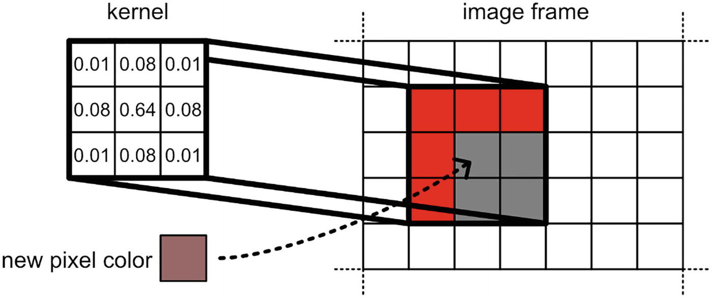
Gaussian blur works by creating a 2D grid of weights, called a convolution kernel, and overlaying the center of the kernel onto a pixel of the image. Each value in the kernel is multiplied by the color of the pixel it overlaps, and the sum of those values becomes the output color of the center pixel. The kernel slides over the image until each pixel has an output. Figure 11-8 demonstrates how convolution works.
A grid plot of an image frame has pixels of different colors, with lighter colors representing newer pixels. The Gaussian core element of the 3 by 3 matrices is ??on the left.
Figure 11-8
Convolving a Gaussian kernel with an image. Each element of the kernel is multiplied by each pixel of the image, and the sum becomes the new center pixel color
When the kernel overlaps the edge of the image, typically the edge pixel color is repeated across the “missing” pixels. The weights associated with each pixel are assigned according to a Gaussian function, named after Carl Friedrich Gauss, hence the name “Gaussian blur.” Here’s what the function looks like:
Equation 11-2: A one-dimensional Gaussian function
If you’ve never seen this function before, then there is a lot going on, so let’s explore what each part of the function is doing:
This version of the Gaussian function operates in one dimension. We put in one value and get back one value.
You don’t need to understand every term in this function. You just need to know what x and σ do and the general shape of the graph.
x is the distance from the center point. The pixel in the center of the kernel is at x = 0. If we evaluate on a pixel adjacent to the center pixel, x equals 1, and so on. This is the input to the function.
σ is the standard deviation, which is a measure of spread. If this value is larger, then the convolution kernel gets larger, and the peak of the graph is smaller.
As you get further from the center point, the values output by the function get lower. The shape of this curve is sometimes called a “bell curve.” If you have used a normal distribution in statistics, then you’ve seen a Gaussian curve before.
Figure 11-9 shows the shape of the Gaussian function in one dimension.
A graph of x versus G of x. It plots a bell shaped curve and from the center point towards the ends the value of G of x decreases.
Figure 11-9
The one-dimensional Gaussian function. As the value of x gets further from the mean value, 0, the value of G(x) decreases
Of course, our images are in two dimensions. You can extend the Gaussian function to cover as many dimensions as you want by taking the product of the one-dimensional Gaussian functions in each dimension. In 2D, the Gaussian function looks like this:
Equation 11-3: A two-dimensional Gaussian function
One of the desirable features of the Gaussian kernel, as exposed by this equation, is that it is separable – that is, a 2D Gaussian kernel returns the same result as running a 1D Gaussian kernel horizontally and then running another 1D Gaussian kernel vertically on the result. In fact, running it this way is a lot more efficient. For example, with a 3 × 3 kernel, the 2D method requires nine multiplications per pixel, but the two-pass 1D method requires only six (three horizontally and then three vertically). However, this becomes slightly more complicated to implement on the shader side, since we need to write two shader passes and customize our code to run both those passes. Nonetheless, let’s see how it can be done in each pipeline.
Gaussian Blur in the Built-In Pipeline
As with the Grayscale effect, the Gaussian Blur effect will require a script and a shader file to work. The difference here, apart from Gaussian blur being conceptually more complicated than grayscale, is that the Gaussian Blur effect will use a two-pass shader rather than Grayscale’s one-pass shader. This will require more work on both the shader and script sides. Let’s see how the script works first.
Gaussian Blur C# Scripting in the Built-In Pipeline
Start by creating a new C#script via Create ➤ C# Script and name it “GaussianBlurEffect.cs”. This script will drive the Gaussian blur post-process by applying the two shader passes in the correct way. Let’s start with the member variables. On top of holding a reference to the material, which the GrayscaleEffect script also did, we will add a public variable for the kernel size so that you can change the amount of blurring within the Unity Editor. As the kernel size increases, more surrounding pixels are sampled in the blur calculation for each pixel, which means there is more blurring. A kernel size of 1 is the same as no blurring. I’ve used the Range attribute to bound the value of the kernelSize variable between 1 and 101 – the kernel always needs to be at least 1 × 1, but my choice of upper bound is arbitrary so you can change it if you want.
using UnityEngine;
public class GaussianBlurEffect : MonoBehaviour
{
[Range(1, 101)]
public int kernelSize;
private Material mat;
...
}
Listing 11-40
Blur variables
After declaring these variables, we’ll use the Start method to create a material using the GaussianBlur shader (which we are yet to write), using the name “Examples/ImageEffect/GaussianBlur”.
private Material mat;
void Start()
{
mat = new Material(Shader.Find("Examples/ImageEffect/GaussianBlur"));
}
Listing 11-41
Finding the GaussianBlur shader
Lastly, let’s handle the OnRenderImage method. The effect uses two passes, so we’ll use a temporary RenderTexture, tmp, as an intermediate by using the RenderTexture.GetTemporary method. Then, we need to set the kernelSize value on the material. We’ll be using a shader property called _KernelSize to do so. Next, by adding an integer fourth argument to Graphics.Blit, we can specify which shader pass to use, so we’ll apply the horizontal pass (0) between src and tmp and then apply the vertical blur pass (1) between tmp (which has now been blurred horizontally) and dst. Once we’re done, it’s important to release the temporary texture we were using to avoid memory issues.
That’s all we need for the script, so let’s move on to the shader itself.
Gaussian Blur Shader in the Built-In Pipeline
There is a lot of overlap between the Gaussian Blur shader and the Grayscale shader, as the appdata and v2f structs are identical, as is the vert function. However, they are all required in both shader passes, so we will include them in an HLSLINCLUDE block in the SubShader. Recall that any code inside such a block gets copied for us to all HLSLPROGRAM blocks in subsequent Pass blocks, reducing the amount of repeated code. We will also be placing all variables and include files in HLSLINCLUDE, as well as a handful of constants and a function to help us calculate the Gaussian coefficients required in the shader passes. The shader looks like the following.
The gaussian function carries out Equation 11-2, given the pixel’s distance from the center of the kernel, x, and the standard deviation, sigma. For that, we need to add two constants, E and PI, to represent Euler’s constant, e, and pi, respectively. Let’s now focus on the contents of the two passes, starting with the horizontal pass that blurs pixels along the x-axis. We’ll name the pass “Horizontal” and then immediately open an HLSLPROGRAM block containing the fragHorizontal function. This function will loop over the kernel and multiply the values from the gaussian function by the underlying colors in the texture.
Pass
{
Name "Horizontal"
HLSLPROGRAM
#pragma vertex vert
#pragma fragment fragHorizontal
float4 fragHorizontal (v2f i) : SV_Target { ... }
ENDHLSL
}
Listing 11-44
The horizontal blur pass for the Gaussian blur effect in the built-in pipeline
Inside the function, we’ll initialize variables for the color, the sum of all kernel values (they may not sum exactly to one, so we will correct for this after the loops), and the standard deviation. We want to calculate the standard deviation such that most of the Gaussian curve fits inside the kernel we’ve created – I found that dividing the _KernelSize by 8 works well. We’ll also calculate the upper and lower bounds of the for-loop.
float4 fragHorizontal (v2f i) : SV_Target
{
float3 col = float3(0.0f, 0.0f, 0.0f);
float kernelSum = 0.0f;
float sigma = _KernelSize / 8.0f;
int upper = ((_KernelSize - 1) / 2);
int lower = -upper;
Listing 11-45
Preparing for the horizontal blur loop
Next comes the loop. In each loop iteration, we’ll calculate the Gaussian coefficient using the gaussian function and add that value to kernelSum. Then, we’ll add a small offset to the UVs to sample a specific pixel along the x-axis, using _MainTex_TexelSize to step by one pixel each iteration. Using those UVs, we’ll sample _MainTex and multiply by the Gaussian coefficient and then add the value to the col variable. I discovered that in some cases the screen texture can contain negative values, so I take the max with 0 to eliminate those cases. Once all loop iterations have executed, col will contain a blurred color value. To correct for kernels whose Gaussian coefficients don’t quite sum to 1, we’ll divide the resulting color by kernelSum and then return the color.
Underneath the horizontal pass, we’ll now deal with the vertical pass. The code is almost identical, except it’s now named “Vertical” and the loop operates in the vertical axis instead.
The vertical blur pass for the Gaussian blur effect in the built-in pipeline
The shader is now complete. If you create a material with this shader and attach it to the camera via the material slot of the GaussianBlurEffect script, you’ll see blurring like in Figure 11-7. Next, let’s see how the effect works in URP.
Gaussian Blur in URP
As with the Grayscale effect, the Gaussian Blur effect is more difficult to write in URP than in the built-in pipeline. However, the scripting side of the Gaussian Blur effect is mostly the same as with the Grayscale effect for URP. Let’s see how the scripting side works and then write the shader.
Gaussian Blur C# Scripting in URP
As with the Grayscale effect, we will be using three separate scripts for the Gaussian Blur effect as follows:
A script called GaussianBlurSettings that controls the variables that will be visible when the effect is attached to a volume
A script called GaussianBlurRenderPass that contains the logic for the effect, such as setting up render textures and applying materials to those textures
A script called GaussianBlurFeature that instructs URP to use our custom render pass in the rendering loop
Since we already know what each type of script broadly does, let’s jump straight into the GaussianBlurSettings script.
The GaussianBlurSettings C# Script
Create a new script via Create ➤ C# Script and name it “GaussianBlurSettings.cs”. This script is responsible for setting up the variables used by the Gaussian Blur effect, which will be visible on any volume using the effect, and it will handle the conditions under which the effect is active. Let’s start by replacing the script’s entire contents with a boilerplate we can work with.
public class GaussianBlurSettings : VolumeComponent, IPostProcessComponent
{
...
public bool IsTileCompatible() => false;
}
Listing 11-48
The GaussianBlurSettings skeleton script
We will be able to add this effect to a volume via the drop-down by finding it under “Examples ➤ Gaussian Blur” due to the VolumeComponentMenu attribute. This script only requires one variable for the kernel size, for which we can use the ClampedIntParameter type to ensure its value is always at least 1, plus a Tooltip attribute to give the variable a nice description. After this, we’ll add the IsActive method from the IPostProcessComponent interface. When the kernel size equals 1, that’s the same as there being no blurring at all, so we’ll only make the effect active when kernel size is strictly above 1. This code all goes above the IsTileCompatible method.
[Tooltip("How large the convolution kernel is. " +
"A larger kernel means stronger blurring.")]
public ClampedIntParameter kernelSize = new ClampedIntParameter(1, 1, 101);
public bool IsActive() => kernelSize.value > 1 && active;
public bool IsTileCompatible() => false;
Listing 11-49
Variables and IsActive method
That’s all we need for the GaussianBlurSettings script, so let’s move on to GaussianBlurRenderPass.
The GaussianBlurRenderPass C# Script
This is still the longest of the three scripts, but there are a lot of similarities with the code from GrayscaleRenderPass, so we can go through a lot of it quickly. This script inherits from ScriptableRenderPass, so we must override the Configure, Execute, and FrameCleanup methods. Plus, we’ll supply a Setup method to create some of the resources needed for the effect. Here’s the base code that we’ll be filling in.
using UnityEngine;
using UnityEngine.Rendering;
using UnityEngine.Rendering.Universal;
public class GaussianBlurRenderPass : ScriptableRenderPass
{
...
public void Setup(ScriptableRenderer renderer, string profilerTag) { ... }
public override void Configure(CommandBuffer cmd, RenderTextureDescriptor cameraTextureDescriptor) { ... }
public override void FrameCleanup(CommandBuffer cmd)
{ ... }
}
Listing 11-50
The GaussianBlurRenderPass code skeleton
Let’s fill in the gaps, starting with the member variables. Like the Grayscale effect, we need a material, a settings object (this time, it’s the GaussianBlurSettings we just wrote), handles to the source texture and main texture, and a profiler tag string. This time, we need an additional temporary texture to use as an intermediary between the two shader passes. I’ll call it tempTex.
public class GaussianBlurRenderPass : ScriptableRenderPass
{
private Material material;
private GaussianBlurSettings settings;
private RenderTargetIdentifier source;
private RenderTargetIdentifier mainTex;
private RenderTargetIdentifier tempTex;
private string profilerTag;
Listing 11-51
The member variables
Next is the Setup method. This method retrieves a handle to the camera source texture, retrieves the effect’s data from the active volume, and creates a material that uses the Gaussian Blur shader. We haven’t written the shader yet, but its name will be “Examples/ImageEffects/GaussianBlur”. The structure of this method is identical to the Setup method in GrayscaleRenderPass.
public void Setup(ScriptableRenderer renderer, string profilerTag)
material = new Material(Shader.Find("Examples/ImageEffects/GaussianBlur"));
renderer.EnqueuePass(this);
}
}
Listing 11-52
The Setup method for the Gaussian blur effect in URP
Now we come to the Configure method, which is overridden from the ScriptableRenderPass base. The primary responsibility of this script is to create the two render textures required to run the shader, which are called _MainTex and _TempTex, respectively. The method runs every frame, so we will need to deal with these textures later.
public override void Configure(CommandBuffer cmd, RenderTextureDescriptor cameraTextureDescriptor)
{
if (settings == null)
{
return;
}
int id = Shader.PropertyToID("_MainTex");
mainTex = new RenderTargetIdentifier(id);
cmd.GetTemporaryRT(id, cameraTextureDescriptor);
id = Shader.PropertyToID("_TempTex");
tempTex = new RenderTargetIdentifier(id);
cmd.GetTemporaryRT(id, cameraTextureDescriptor);
base.Configure(cmd, cameraTextureDescriptor);
}
Listing 11-53
The Configure method for the Gaussian blur effect in URP
Once the textures have been set up, we can move to the Execute method, which carries out the effect. The structure of the method is like the Execute method from GrayscaleRenderPass, except this is a two-pass effect, so we will need an additional call to Blit. The script will do the following:
Immediately exit and do nothing if the settings’ IsActive method returns false.
Create the command buffer, cmd.
Copy the source texture to mainTex ready to run the effect.
Set the shader’s _KernelSize property value to the kernelSize value from the volume settings.
Perform the first Blit from mainTex to tempTex using shader pass 0.
Perform the second Blit from tempTex back to source (which is also the output texture) using shader pass 1.
Execute the command buffer, thereby running the steps outlined previously.
Remove all commands from the buffer and release the command buffer back to the command buffer pool.
public override void Execute(ScriptableRenderContext context, ref RenderingData renderingData)
The Execute method for the Gaussian blur effect in URP
Finally, we come to the FrameCleanup method, which we use to clean up all resources created temporarily during the frame. We already cleared the command buffer during Execute, so that just leaves the two textures we created back in Configure. The ReleaseTemporaryRT method will clean up the textures.
public override void FrameCleanup(CommandBuffer cmd)
The FrameCleanup method for the Gaussian blur effect in URP
The GaussianBlurRenderPass script is now complete. Hopefully, you found it a lot less complicated seeing it for a second time! Now we can move on to the final of the three scripts, GaussianBlurFeature.
The GaussianBlurFeature C# Script
Create this script via Create ➤ C# Script and name it “GaussianBlurFeature.cs”. This is the simplest of the three scripts. It inherits from ScriptableRendererFeature, so we need to override the Create and AddRenderPasses methods. Create just needs to name the effect and instantiate a GaussianBlurRenderPass. Then the AddRenderPasses method can just call Setup on that pass, since we delegated all the setup code to the GaussianBlurRenderPass class.
using UnityEngine.Rendering.Universal;
public class GaussianBlurFeature : ScriptableRendererFeature
{
GaussianBlurRenderPass pass;
public override void Create()
{
name = "Gaussian Blur";
pass = new GaussianBlurRenderPass();
}
public override void AddRenderPasses(ScriptableRenderer renderer, ref RenderingData renderingData)
{
pass.Setup(renderer, "Gaussian Blur Post Process");
}
}
Listing 11-56
The GaussianBlurFeature script
The scripting side of the effect is complete, so we can move on to the Gaussian Blur shader itself.
Gaussian Blur Shader in URP
Create a new shader file and name it “GaussianBlur.shader”. Then clear its contents entirely so we can write it from scratch. This post-processing shader uses two passes, so we will place all the common code for the two passes inside the HLSLINCLUDE block, so we don’t need to type it all twice. This common code includes the appdata and v2f structs, the vert function, and the shader properties, plus the gaussian function that we’ll use to calculate the Gaussian coefficients according to Equation 11-2. We’ll need to include Euler’s constant, e, as a constant variable, but pi is already contained in the Core include file, so we won’t need to include it here unlike in the built-in pipeline.
For the two passes, the code is identical to Listings 11-45, 11-46, and 11-47 from the built-in pipeline version of the shader, so we will copy that code here.
Like we saw with the Grayscale shader, add the Gaussian Blur effect to a profile, attach the profile to a volume, and add Gaussian Blur to the Renderer Features list to see blurring like in Figure 11-7 in your scene. Finally, let’s see how this effect works in HDRP.
Gaussian Blur in HDRP
As with the other render pipelines, the Gaussian Blur effect in HDRP has a C# scripting side and a shader side. We can use the same template files as the ones we used in the Grayscale effect. Let’s see how each part works.
Gaussian Blur C# Scripting in HDRP
Unlike URP, we require only one C# script to drive the Gaussian Blur effect in HDRP. We can create it using the template at Create ➤ Rendering ➤ C# Post Process Volume, and I’ll name it “GaussianBlurVolume.cs”. I’ll make a few changes to the template, so we’re left with the following code as a starting point.
public sealed class GaussianBlurVolume : CustomPostProcessVolumeComponent, IPostProcessComponent
{
...
public override void Setup() { ... }
public override void Render(...) { ... }
public override void Cleanup() { ... }
}
Listing 11-58
The GaussianBlurVolume code skeleton
We already saw how post-processing scripts broadly work in HDRP when we wrote the Grayscale shader, so let’s quickly go through each part. First, we need to add a kernelSize member variable for the shader, plus a variable to store the material used by the effect. We will be using a temporary render texture because Gaussian Blur is a two-pass effect, so we will also store an RTHandle object called tempTex. Recall that RTHandle is a type that abstracts many of the features of a RenderTexture. We’ll also add the IsActive method, which is true only when the material exists and the kernel size is above 1, the injection point for the effect, and the shader’s name string.
public sealed class GaussianBlurVolume : CustomPostProcessVolumeComponent, IPostProcessComponent
{
[Tooltip("How large the convolution kernel is. " +
"A larger kernel means stronger blurring.")]
public ClampedIntParameter kernelSize = new ClampedIntParameter(1, 1, 101);
The Setup method, which is responsible for creating the material used by the effect, is practically the same as the version we wrote for the Grayscale shader, except the error message is slightly different. This goes just below the variable declarations.
public override void Setup()
{
if (Shader.Find(kShaderName) != null)
m_Material = new Material(Shader.Find(kShaderName));
else
Debug.LogError($"Unable to find shader '{kShaderName}'. Post Process Volume Gaussian Blur is unable to load.");
}
Listing 11-60
The Setup method for the Gaussian blur effect in HDRP
Now we come to the Render method, which sets up the logic for the effect. We will be using a temporary render texture, which is a bit more finnicky in HDRP than URP. We use the RTHandles.Alloc method to retrieve a render texture from the pool. This method can accept many different optional arguments, but the one we are interested in is the first parameter, scale factor, which is a Vector2. A value of (1, 1) represents a render texture with the same dimensions of the screen; this syntax is helpful if you want to access textures smaller than the maximum screen size without needing to manually deal with accessing the screen size and performing the size divisions yourself. In our case, we want a texture the same size as the screen. Hence, we will use Vector2.one.
HDRP can act a bit strangely with temporary textures. Personally, I have run into many issues getting them to work, as there are several ways of creating and using them, and most of the methods I have tried result in a black or gray screen when trying to apply the effect. The following method works well:
First, we’ll send the source texture to a texture slot named _SourceTex in the shader.
Then, apply the first shader pass with HDUtils.DrawFullScreen, saving the result in tempTex.
Next, we’ll send the tempTex texture to a new texture slot called _TempTex in the shader.
Finally, we’ll apply the second shader pass, saving the result in the destination texture.
This means the HDRP Gaussian Blur shader will use two texture names instead of one. This is because the format of the source texture is different from the format of tempTex, so we need to sample each one using slightly different functions – this will be important when we write the shader, so just bear it in mind for now. Here’s the Render method.
The Render method for the Gaussian blur effect in URP
Finally, we come to the Cleanup method. This method is responsible for cleaning up resources used by the shader each frame, which in this case are the material and the tempTex texture.
public override void Cleanup()
{
tempTex.Release();
CoreUtils.Destroy(m_Material);
}
Listing 11-62
The Cleanup method
Now that the code is complete, let’s move on to the shader file.
Gaussian Blur Shader in HDRP
Create a new post-processing shader via Create ➤ Shader ➤ HD Render Pipeline ➤ Post Process and name it “GaussianBlur.shader”. Much of the template will stay the same. In the HLSLINCLUDE block, we will add a gaussian function that calculates the Gaussian coefficients at a given distance from the center of the kernel. We will also be including the _KernelSize, _SourceTex, and _TempTex properties, but pay close attention to the type of those two textures. The fragment shader changes between the two passes, so we will remove it from HLSLINCLUDE and write the two new fragment shader functions in the corresponding Pass blocks.
Shader "Examples/ImageEffects/GaussianBlur"
{
HLSLINCLUDE
#pragma target 4.5
#pragma only_renderers d3d11 playstation xboxone xboxseries vulkan metal switch
The TEXTURE2D_X macro is used for VR games so that the shader can use separate textures for each eye – the template shader file uses this type of texture for the source texture by default. The TEXTURE2D type (without the X on the end) is just a regular texture. I’m using the latter type for _TempTex because this is the only method that seems to work reliably for multipass shaders. This means we’ll need to make sure we use the correct sampling macro later too.
Let’s move on to the two passes. The first pass, named “Horizontal”, blurs the image horizontally. We’ll use a similar approach as we saw in the Grayscale post-process shader by converting the UVs to screen-space coordinates, which are used by the LOAD_TEXTURE2D_X macro to sample a texture, which in this case is _SourceTex. The loop for the blurring process is similar to the loops used in the built-in pipeline and URP versions of this shader.
col += max(0, gauss * LOAD_TEXTURE2D_X(_SourceTex, uv).xyz);
}
col /= kernelSum;
return float4(col, 1.0f);
}
ENDHLSL
}
Listing 11-64
The horizontal blur pass for the Gaussian blur effect in HDRP
Lastly, let’s write the second pass, called “Vertical”. It is much the same as the first pass, except it operates in the y-direction, so the loop is slightly different. Most importantly, make sure you use the LOAD_TEXTURE2D macro this time instead of the “X” version, because we are sampling a different type of texture in this pass.
col += max(0, gauss * LOAD_TEXTURE2D(_TempTex, uv).xyz);
}
col /= kernelSum;
return float4(col, 1.0f);
}
ENDHLSL
}
Listing 11-65
The vertical blur pass for the Gaussian blur effect in HDRP
Now that the shader file is complete, we can set up the effect. We’ll take the same steps as we did for the Grayscale shader: create a profile and add the Gaussian Blur effect to it and then attach the profile to a volume in your scene. Make sure the Gaussian Blur effect is included in the Custom Post Process Orders ➤ After Post Processing list in the HDRP Project Settings. Then your effect will appear in both the Scene View and Game View when the camera passes through the volume, as in Figure 11-7.
Summary
Post-processing effects can be used to add an extra layer of polish to your game or to create entirely new mechanics that rely on graphics. With post-processing shaders, also known as image effects, we can change the way the game looks in ways that are not possible with conventional object shaders. Image effect shaders operate on every pixel of the screen, changing their colors in any way you want. Each render pipeline in Unity deals with post-processing in different ways, so unfortunately each pipeline requires a unique approach to custom post-processing effects. In this chapter, we learned the following:
Render textures are special types of texture that contain the output from a camera.
You can create render textures in the Editor and assign them to a camera or create them programmatically and then use them in materials.
A Grayscale effect takes the luminance of each pixel based on the real-world sensitivity of the human eye to red, green, and blue light and then outputs that luminance value as a grayscale color.
An efficient type of blur called Gaussian blur uses the Gaussian function to assign coefficients to each entry in a kernel matrix.
The kernel is run over (“convolved with”) each pixel of the image to produce an output color for the center pixel.
The Gaussian blur is separable, so we make performance gains by running two passes, one horizontally and the other vertically.
URP and HDRP can make use of the SRP volume system, which is able to blend post-processing effects together or fade them in and out.