
Shader programming is at a somewhat strange crossing of disciplines. Obviously, since there is code involved, you need some amount of programming ability, but many people who write shaders bring their programming experience from other languages rather than learning shaders from scratch as their first language. If you are only interested in writing shaders, then there are many concepts you may need to learn from scratch, which increase the barrier to entry. If you’re an artist wishing to write shaders, but you have no programming experience, then shaders can seem daunting. There’s a tool that is perhaps more approachable for artists due to the lack of programming while still being usable by programmers: Shader Graph.

A zoomed out view of the shader graph depicts the noise sample, glowing edges, world space cutoff, main preview, vertex, and fragment.
A zoomed-out view of a Shader Graph that dissolves the edge of a mesh
Shader Graph Overview
Shader Graph has several advantages over traditional code. First, and most obviously, code is no longer required. Artists who wish to avoid coding, or programmers who prefer a change of pace from staring at lines of code, will be able to put together many of the same shaders that shader programmers have had access to for years.
Second, it becomes easier to see at a glance what the shader is doing at each stage. With code shaders, it can be difficult to debug problems or visualize what the result will be until you have finished writing the entire shader (although there are tools that you can use to assist with shader debugging), but Shader Graph displays a preview window on many of its nodes, which gives you immediate feedback without needing additional windows or tabs open in Unity.
And, third, Shader Graph does some of the boilerplate work for you. We saw in the previous chapter that, for example, we need to handle some of the matrix transformations during the vertex stage if we’re using code (although we are supplied with macros and functions to make it easier), but with Shader Graph we don’t even have to worry about that. Furthermore, some of the nodes included in Shader Graph give us access to some complex behavior that otherwise would take a nontrivial amount of work to implement ourselves in code.
Shader Graph is not without its drawbacks. Shader Graph does not support every kind of shader, such as geometry shaders or compute shaders, although support for these could be added in future updates. Also, your graphs are compiled into shader code in the end, but as with many other systems that automatically generate code, you can usually get better performance out of a hand-authored code shader than an equivalent graph.
This book was written for Unity 2021.3 in mind, so versions of Shader Graph before and after this version may look different. If the things I talk about don’t quite match up to what you see, then you might need to spend a little time looking up the differences between versions, but the information in this book will almost certainly still be relevant.
Creating a Basic Shader in Shader Graph
In Chapter 3, we learned how to use shader code to build a basic shader, which lets us customize the color of an unlit object. In this section, we will see how to create a similar effect in Shader Graph.
Scene Setup
- Go to Window ➤ Package Manager to open the Package Manager window. This window is shown in Figure 4-2.

A screenshot of the package manager window depicts the process of choosing the unity registry in the packages drop down and lists various packages with the shader graph.
Figure 4-2The Package Manager window, which we use to install Shader Graph
Use the Packages drop-down at the top to pick “Unity Registry,” which lists all possible packages.
Scroll down to find the entry for Shader Graph. If it’s installed, it will have a green tick beside it. If not, click the Install button in the bottom left of the window.
In all pipelines, you will see the option to create a Blank Shader Graph or a Sub Graph. We’ll explore the latter option later in the book.
In the built-in pipeline, there are also Lit and Unlit options.
In URP, you have an expanded set of options, including Lit, Unlit, Decal, Sprite Lit, and Sprite Unlit. The latter two are intended for use with 2D sprites.
In HDRP, you have the most options: Lit, Unlit, StackLit, Decal, Eye, Fabric, and Hair.
No matter which render pipeline you are using, we will pick the Unlit option (we will see the other options in later chapters). This creates a new asset with a .shadergraph extension, which I’ll call “HelloShaderGraph”.
The types of preset that are available will change between versions. Notably, if you see an option called PBR Graph, then this was renamed to Lit Graph in Unity 2020.1, but it does broadly the same thing.
Like we did for the shader code examples, we will also add a sphere to the scene and create a new material to use our shader. In the Shader drop-down at the top of the Inspector on the material, all graphs are included in a folder called “Shader Graphs” by default – it’ll have the same name here as the one you gave to the file when creating it, which in my case is “HelloShaderGraph”.
The Shader Graph Interface

A screenshot of the new shader graph window depicts the graph settings under the graph inspector, main preview, vertex, and fragment.
A brand-new, unmodified Shader Graph
Inside the Shader Graph editor, there are several sub-windows and toolbars, so let’s explore each one in turn.
The Toolbar
Click the Save Asset button if you want changes to your graph to be visible back in the Scene View.
Save As is similar and lets you save the graph under a new filename.
Show in Project focuses the editor on the file that the current graph is saved in.
The Check Out button checks out the current file with source control (this option is grayed out if source control is not enabled).
The Color Mode option controls how Shader Graph displays some nodes. By changing this option to something other than None, Unity adds a small colored ribbon to the top of each node depending on the option chosen.
The other three options (Blackboard, Graph Inspector, and Main Preview) are toggles that turn on or off the corresponding window.
Speaking of which, let’s explore those windows now.
Togglable Windows
The Blackboard is a separate draggable mini window where we can define properties and keywords, which act as the inputs to the graph, like we saw in shader code. It can be found on the left-hand side of the editor (see Figure 4-3). By default, a property can be overridden on any material that uses this shader, so we can create several materials with this shader with different behavior. We will see how to add properties soon.
Graph Settings, which displays graph-wide information and lets us customize the macroscopic behavior of the graph.
Node Settings, which displays options for any node or property we have highlighted.
Single, contrary to how it sounds, is the higher-precision type.
Half is lower-precision type.
I usually stick with Single, but Half may have better performance (while impacting quality), especially on mobile devices.
Finally, there is the Main Preview window, which displays what your graph will broadly look like when added to your game. You can right-click this box to change the type of mesh used in the preview, including a custom mesh of your own. There are a few limitations to this, however. This window will simulate only one directional light, so if you expect this material to exist near many light sources, then it may not be an accurate representation of how the object will appear in-game. For most use cases, it’s a good approximation. All of this is important of course, but we’re most interested in the middle of the window.
The Graph Environment
The vertex stage is like the graph’s vertex shader. Here, we can influence the individual vertices of the mesh.
The fragment stage operates on fragments (or pixels). We can apply color, lighting, and texture to an object here.
Each section can be moved independently, although there will always be a link between the two. Since each block is an output from the graph, I sometimes refer to the master stack as the “output stack,” the “graph outputs,” or just the “outputs.”
Inside both sections of the master stack, you will see a few graph outputs called blocks. The vertex stage section always contains three blocks for the vertex position, normal, and tangent vectors by default. These blocks have default values attached to them, so if we want our effect to use a basic vertex shader that just places vertices into the correct place on-screen, we don’t need to add any nodes or make any changes whatsoever to the vertex stage. This is quite different from shader code, where even the simplest vertex shader requires a relatively high amount of boilerplate code. We also don’t need to define any of the graph input data such as positions and texture coordinates like we do when writing shader code, so it is often faster to make a basic shader effect using Shader Graph than using shader code.
Since we picked the Unlit preset, the fragment stage only contains the Base Color block. It uses a default light-gray color if we don’t attach anything to it, but we can click the tiny color block next to it to modify the color. By adding zero nodes or properties, we already have a shader that we can use to output a basic color of our choosing. However, it is preferable to modify settings like this per material, for which we require properties.
Adding Properties

A screenshot depicts the column with different property types with a clickable plus icon on the right side of the Hello Shader Graph board.
Clicking the “+” button on the Blackboard brings up a list of property types

The screenshot of the graph inspector window depicts selected node settings, with various property options with settings.
When a property is selected, the Node Settings window displays options for the property
Let’s go over each setting.
Property Naming
Some of the settings are specific to certain types of property, but you will always see Name and Reference options. You can set whatever Name you want, and it will appear when you drag the property onto the central Shader Graph surface. The Reference string is the name Unity gives to the property when it autogenerates code based on our graph. For the Reference string, the convention is to start with an underscore – Unity will prepend one to the name invisibly if you miss it out here. I usually name it the same as, or similar to, the Name, but without spaces and with an underscore at the start.
To reset a property name if you make changes to it, right-click the property on the Blackboard and select Reset Reference. I will change the reference value of my property to _BaseColor. Next, we’ll go over other common options seen on most property types.
Common Property Options
We can change the default value of the property with the Default option. This setting obviously changes based on the property type! In the case of Color properties, clicking the box will bring up Unity’s color picker window and let you choose any RGB color you’d like. I change the default to white in most cases, but this will depend on what you’re using the color for.
These properties can still be modified externally at runtime through C# scripting, as we will see later.
Helpfully, any property that is exposed will have a small green dot next to its name to help you distinguish between exposed and non-exposed properties.
Some property types, such as Gradient, cannot be exposed; even though the option appears, the checkbox can’t be ticked.
Per Material is the default option, which means that the value of this property can differ between material instances.
The Global option means that the variable is declared globally instead, but this can break compatibility with the SRP Batcher, so only use this option if you know what you’re doing.
The Hybrid Per Instance option is related to the DOTS Hybrid Renderer, which is outside the scope of this book.
Next, let’s see the options that are exclusive to Color properties.
Color Property Options
The next setting for a Color is the Mode, which has two values: Default, which we use for regular colors, and HDR, which lets us use values beyond the typical 0–1 range. The HDR setting adds an additional Intensity value to the color picker, where intensities above zero may push the RGB values above 1. HDR colors are useful for emissive color, which we will see later. I will leave it as Default for now.
I briefly covered the types used in shader code at the end of Chapter 3. The options in Shader Graph are Single and Half, which map to the float and half types, respectively.
The Inherit option uses the graph’s global precision setting. Half-precision floats use half the number of bits as single-precision floats, but the optimization impact is small, so don’t worry about overzealously managing which setting you use on each node and property.
Other types might have more options, but you should have a good understanding of the kinds of settings available on properties in Shader Graph. Now that we have added a Color property, let’s start using it in the graph.
Building the Graph
In the middle of the graph environment, we can chain nodes together to build up the behavior of the shader. Eventually, our chains of nodes need to link up to one of the outputs on the master stack, but first, we need to put some nodes on the graph to link up in the first place.
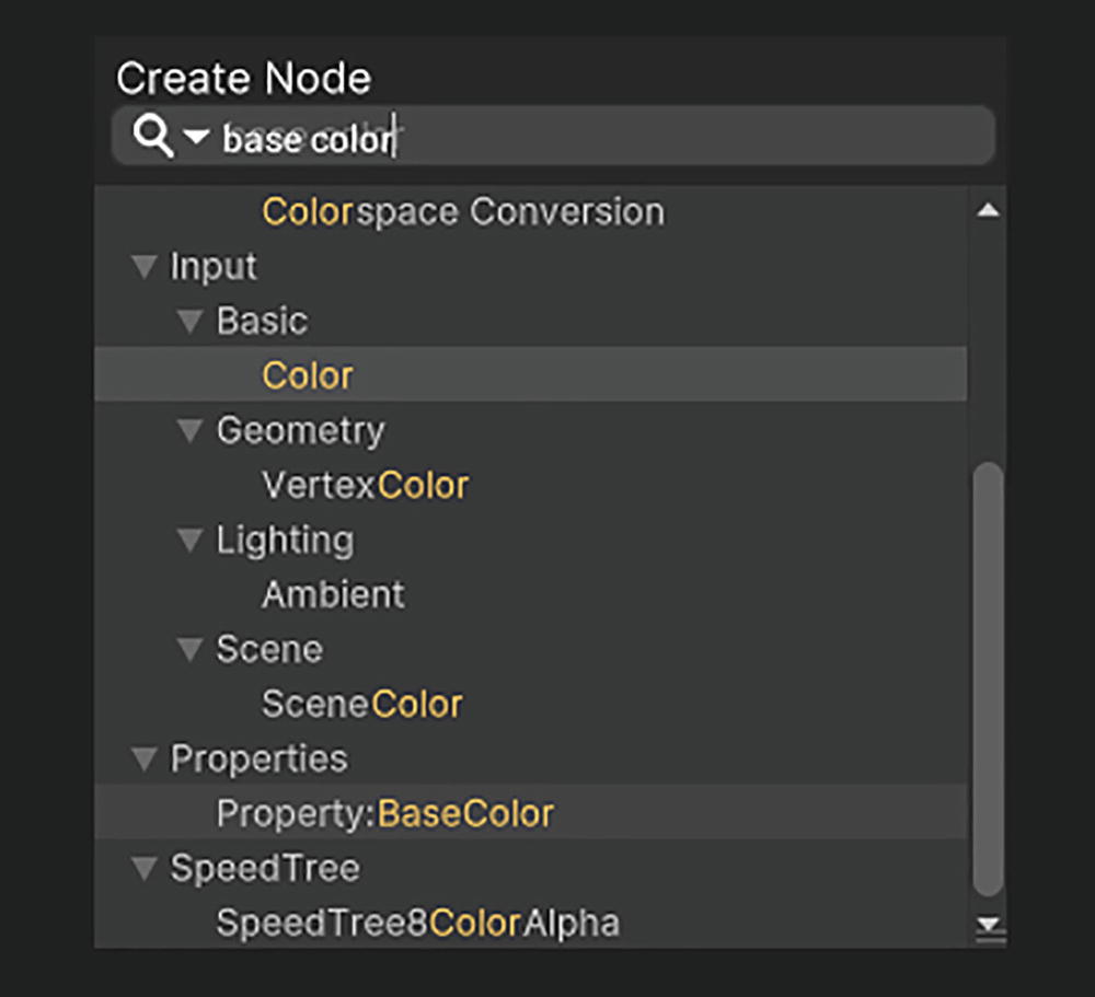
A screenshot of the create node window with the base color in the search bar depicts various suggestions for the color and the base color words.
Adding a node to the graph by searching its name
If we want to add the Base Color property we created to the graph, we can use the Create Node window and type in “Base Color,” or we can click the Properties drop-down and choose Property:BaseColor. You can also left-click and drag the property from the Blackboard onto the graph surface. Once you have added it using one of those methods, you will see it on the graph as a small, rounded box. It won’t do much on its own, so we need to connect it with something.

A screenshot of the hello shader graph window with base color under property depicts node settings under graph inspector with options for vertex, and fragment.
A basic graph that lets us tint an unlit object a specific color

A screenshot of the Hello Graph material window depicts the shader, base color option, and color shaded circle under the hello graph.
When this shader is attached to a material, we can tint it using the Base Color property
Congratulations! You just finished creating your first shader with Shader Graph! Now, let’s see some of the other unique features of Shader Graph and how to use them.
Shader Graph Features
Shader Graph has several features to help you with making shaders. Some of them are like features you would find in shader code, such as Sub Graphs, which are an abstraction of functions. Others only make sense in a graph environment. Let’s see what these features are and understand how we can use them to organize graphs and speed up our shader design workflow.
Adding Blocks to the Master Stack
Blocks on the master stack act as the outputs from your graph. The blocks that are available to you will be different depending on the render pipeline you are using and which of the two shader stages you are adding a block to. There are two ways of changing the blocks available on your master stack. We can add blocks manually by right-clicking the shader stage within the master stack that you want to add the block to and selecting Create Node (or using the spacebar shortcut). The list contains all blocks available on your current pipeline.

A screenshot of the graph inspector window depicts the process of adding an alpha option under blend by changing the surface's opaque option to transparent.
Changing from Opaque to Transparent rendering adds an Alpha block
Redirect Node

A screenshot of a window depicts the vertex, the fragment, and the base color with redirect nodes.
The redirect node can be used to organize graphs such that connections between nodes can be followed more easily on complicated graphs
Preview Node
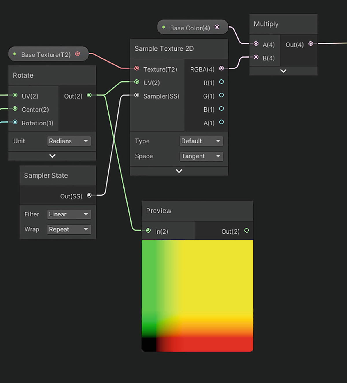
A screenshot of a shader graph depicts the process of creating rotate node from the sample texture 2 D with the sampler state node and the rotation properties.
To expand the Rotate node in this graph snippet to see its preview window, you would have to move the Sampler State node out of the way. It is potentially easier to drag out a Preview node instead
Color Mode
One of the options on the toolbar of the Shader Graph window is the Color Mode, which can be used to identify nodes more easily. By switching to an option other than None, you will see a small ribbon of color below the name of each node. If you select User Defined, then you will need to set the color on each node yourself by right-clicking it and choosing the new Color option from the menu and setting whatever color you’d like.
Shader Path

A screenshot of the example material window has a shader drop down with a marked shader graphs option. The Hello Shader Graph under the shader graphs is selected.
The default path for your graphs is Shader Graphs/{YourGraph}
Node Groups

A screenshot of a window depicts, sample texture 2 D, tiling and offset with a sticky note, sampler state, and base texture with nodes.
Groups can be used to encapsulate nodes that work together toward a single goal. Sticky notes can be used to add more context to nodes in case it is not immediately obvious why you made your graph in a certain way
Sticky Notes
In shader code, it is easy to add code comments using // for single-line comments and /* */ pairs for multiline comments. The equivalent mechanism in Shader Graph is sticky notes. To add one, right-click an empty section of the graph and select Create Sticky Note from the menu. You can edit the title and body of the note separately, resize the note, and move it around anywhere on the graph. This lets you give a little more context to someone looking at your graph if there’s a section of nodes that are particularly complicated. I often use them in combination with groups by using the note to describe what the group is doing in more detail than the group title can. Figure 4-13 shows you what a sticky note might look like.
Node Snapping

A screenshot depicts the U V node, the tiling node, and the dragged offset node of the Tilling and Offset.
The Offset property node in this example is being actively dragged. The guidelines are snapping its right-hand side to the UV node and its top and bottom edges to the Rotation Amount property node
Sub Graphs
Sub Graphs are Shader Graph’s replacement for functions. While creating a graph, you might find yourself repeating the same group of nodes several times. When this happens, consider bundling that group of nodes into a separate Sub Graph that can be referenced by the main graph. We can use a single Sub Graph in several other graphs or even use Sub Graphs within Sub Graphs. Although they are officially called “Sub Graphs,” I often refer to them as subgraphs, without the space.
The first is to right-click in the Project View and select Create ➤ Shader ➤ Sub Graph, which creates an empty subgraph.
The other method is to select a group of nodes on any existing graph, then right-click, and select Convert To ➤ Sub Graph, which automatically creates the subgraph for you, complete with the correct inputs and outputs.
Let’s make a subgraph from scratch that takes a color as input and inverts its RGB value.
Color Invert Sub Graph
First, create the subgraph using the first method I just mentioned. I’ll call it “InvertColors”. The environment looks like a regular graph, except you will see an Output node in place of the master stack. If you click it and look at the Node Settings, you’ll see a section called Outputs – we can add or remove entries and change the name and type of each output. Left-click a name to edit it. For this subgraph, we only need a single output color, so make sure there is a single output, rename it to “Output”, and make sure its type is Vector 4.

A screenshot of the window depicts an invert colors subgraph with an input of 3 color nodes and alpha, an output node, and node settings under graph inspector.
A Sub Graph for inverting any color that is input to the graph

A screenshot of a window depicts the invert color subgraph with a base color node connected to its input color and output to the base color of the fragment.
Sub Graph nodes are used in graphs like any other regular type of node
Custom Function Node
Shader Graph does not ship with a node for every shader function imaginable. Although it comes with over 200 nodes for a multitude of uses, you might sometimes find that a node just doesn’t exist for what you want to do. In that case, you have two choices. You can recreate the feature yourself by using the other nodes that exist and packaging them together in a Sub Graph or node group. Or, if you’re coming to Shader Graph from a shader code background, you can use the Custom Function node. You won’t use this node very often unless you need to run some very specialized code that isn’t provided by any of Shader Graph’s nodes, but I will mention it now because it is a very powerful tool in our arsenal that partially crosses the gap between code and graph. Let’s try the invert color example again, but this time we will use a Custom Function node.
Color Invert Custom Function

A screenshot of a window displays the node settings in the graph inspector with a custom function node, with a checkerboard pattern and an error mark.
A custom function node with one input and one output defined, but no code body
The next option is the Type. There are two settings – first, we will explore the String setting, which lets us write the custom code directly inside the Node Settings window.
Custom Function String Mode
A snippet of custom code that takes each color channel of the Color input and outputs one minus the channel value, respectively
Two versions of a function that inverts a color using either single or half precision, generated by the Custom Function node
This interface is restrictive because you can only type a single function inside the body. There may also be instances where your code needs to differ between precision settings, but it’s impossible to do this in String mode. Let’s see how to remedy this.
Custom Function File Mode
In File mode, we solve both these problems: we can define several functions inside a single file and then pick one to use in the Custom Function node. In most cases I would recommend using File mode. If we were to copy and paste Listing 4-2 into a separate file named “Invert.hlsl” and save it inside your project’s Assets folder, we could drag that file onto the Source field, and all errors on the node should disappear.
You’ll have to create the Invert.hlsl file in an external program, because Unity doesn’t have an option to create HLSL files directly.

A screenshot of a window displays the node settings in the graph inspector, and an invert custom function node with a base color node linked to color.
A completed Custom Function node using a file containing custom code
Here, Unity will pick between the invert_float and invert_half functions based on the Precision of the node, which you can change using the option at the top of the Graph Inspector.
Summary
In Shader Graph, we connect nodes together to create a shader.
The master stack is a list of shader outputs that we can modify.
Graphs are eventually compiled to shader code under the hood, although the generated code is often less optimized than an equivalent hand-authored shader.
Most nodes provide a real-time preview of the output, which makes it easy to see what each stage of the shader is doing.
We can define shader properties on the Blackboard and expose most property types to the Inspector.
The Graph Inspector provides options for the graph as a whole and for individual nodes when they are selected.
Shader Graph provides multiple features for organizing your graphs such as redirect nodes, node snapping, node groups, and sticky notes.
Sub Graphs can be used to bundle together commonly used groups of nodes, like functions in shader code.
The Custom Function node can be used to inject custom shader code into nodes.