You’ve almost made it to the end of the book – congratulations! By now, your shader technique arsenal should be full to bursting. With the things we have learned throughout the book, you should be well equipped to make shader effects of all kinds in your own games. However, there are many shader effects and tidbits I keep coming back to, so I decided the final chapter of this book should unleash a handful of important case studies that you will be able to build on in your own games.
World-Space Scan Post-Process
When writing an image effect shader, you typically have access to a quad mesh that covers the width and height of the screen and a texture that was rendered by the camera. A result of this is that you don’t have easy access to a way to get the world space of the objects in the scene, but this would be useful for many types of effect, such as a world scanner post-process or high-quality outlines. In this section, we will reverse engineer the world-space position of each pixel in the scene using the depth texture and then use it to build shader effects that couldn’t be done outside of world space. As with the other post-process effects we saw in Chapter 11, the code will differ significantly between the built-in pipeline, URP, and HDRP, and we will be unable to write the effect in Shader Graph.
A hexad of photographs portrays the world space scan effect, from low level to high level, and highlights the cubes scattered on the surface.
Figure 14-1
The world-space scan effect. The effect starts small (top left) and gets progressively larger over time (from left to right, top to bottom)
Note
The scan effect as I’ve written it for each pipeline will eventually continue until it reaches the skybox. That might be what you want, or you could add code to cut off the scan at certain depth values or fade the scan over time through scripting.
Across the three pipelines, we will use the same set of properties to control the effect, although they may take slightly different formats in each pipeline. The properties are as follows:
bool enabled – The scan will only be visible and propagate across the scene when this is set to true.
Vector3 scanOrigin – The world-space origin point of the scan. The scan will start here and travel outward away from this point.
float scanSpeed – The speed, in meters, of the scan when it is enabled.
float scanDist – The distance, in meters, that the scan has traveled from the origin point.
float scanWidth – The width, in meters, of the scan visuals. We’ll be using a ramp texture, so this value represents how much that texture gets stretched across the world during the scan.
Texture2D overlayRampTex – The ramp texture representing the scan visuals. This texture is x-by-1, meaning that only the horizontal data matters.
Color overlayColor – An additional tint color applied to the overlay texture. Using the ColorUsage attribute, we can make the color picker HDR-compatible and alpha-compatible.
With this in mind, let’s delve into writing the effect for the built-in pipeline first.
World-Space Scan in the Built-In Pipeline
As we saw in Chapter 11, post-processing shaders come in two parts: the scripting side and the shader side. We’ll be starting with the scripting side first.
World-Space Scan C# Scripting in the Built-In Pipeline
The world scan effect works by calculating the distance between the world-space position of each part of the scene and the origin point of the scan. Typical mesh shaders can get the world-space position of a vertex or fragment by multiplying the object-space position by the _ObjectToWorld matrix (also called UNITY_MATRIX_M), but that isn’t possible in image effect shaders because we don’t have access to the original object-space positions of each mesh in the scene. Image effect shaders only have access to a full-screen quad mesh, so we need to “reverse engineer” the data from the depth texture. Therefore, we will calculate the clip-space position of each pixel and then use the inverse view-projection matrix to obtain the original world-space position. I mention all this here rather than in the shader section because we’ll need to pass the inverse view-projection matrix to the shader manually.
Note
As we’ll see, in URP or HDRP, Unity declares a matrix for use in shaders called UNITY_MATRIX_I_VP, short for “inverse view-projection,” which does precisely what we want. Frustratingly, this matrix isn’t automatically available in built-in pipeline shaders, so we must create it in C# and pass it to the shader manually.
Start by creating a new C# script named “WorldScanEffect.cs”. This script can be attached to any GameObject, but I prefer to attach it to the main camera. First, we will deal with the effect’s properties. Alongside those listed when I first described the world scan effect, we also need private references to a material (which we’ll use to apply the image effect) and a camera (which will be the main camera). In Listing 14-1, you’ll see these properties, with descriptive tooltips, plus the empty method signatures for the rest of the class. We’ll fill these methods in next.
using UnityEngine;
public class WorldScanEffect : MonoBehaviour
{
[Tooltip("Is the effect active?")]
public new bool enabled = false;
[Tooltip("The world space origin point of the scan.")]
public Vector3 scanOrigin = Vector3.zero;
[Tooltip("How quickly, in units per second, the scan propagates.")]
public float scanSpeed = 1.0f;
[Tooltip("How far, in meters, the scan has travelled from the origin.")]
public float scanDist = 0.0f;
[Tooltip("The distance, in meters, the scan texture gets applied over.")]
public float scanWidth = 1.0f;
[Tooltip("An x-by-1 ramp texture representing the scan color.")]
public Texture2D overlayRampTex;
[ColorUsage(true, true)]
[Tooltip("An additional HDR color tint applied to the scan.")]
In Start, we must create a material instance and find the main camera. I’ll also ensure the depth texture mode of the camera is set appropriately so that it generates a depth texture, because we’ll be needing it in the shader. We haven’t yet written the shader, so Shader.Find will fail to actually find anything if you run the code.
private void Start()
{
mat = new Material(Shader.Find("Examples/ImageEffect/WorldScan"));
cam = Camera.main;
cam.depthTextureMode = DepthTextureMode.Depth;
}
Listing 14-2
Creating the effect material and finding the main camera
Next comes the Updatemethod. To quickly test the scan, we’ll use some of Unity’s default input functionality to start the scan at the current position or stop the scan entirely. We will also increment the value of scanDist each frame so the scan can propagate further.
private void Update()
{
if (Input.GetButtonDown("Fire1"))
{
StartScan(transform.position);
}
else if (Input.GetButtonDown("Fire2"))
{
StopScan();
}
if (enabled)
{
scanDist += scanSpeed * Time.deltaTime;
}
}
Listing 14-3
Starting, stopping, and propagating the scan
The StartScan and StopScan methods themselves are very simple. They both set the value of enabled as appropriate, but StartScan also resets the scan distance and origin point.
private void StartScan(Vector3 origin)
{
enabled = true;
scanOrigin = origin;
scanDist = 0.0f;
}
private void StopScan()
{
enabled = false;
}
Listing 14-4
The StartScan and StopScan methods
And, finally, the juicy bit: the OnRenderImage method, where we apply the image effect. First, the method checks whether enabled is set to true and whether a ramp texture has been set – if either is not the case, then we won’t apply the effect material. Otherwise, we’ll calculate the inverse view-projection matrix by grabbing the view matrix and projection matrix separately from the camera, multiplying them, and then taking the inverse. Then, as we saw in other post-process scripts, we’ll set all the shader properties and call Graphics.Blit to apply the effect with the material.
The camera’s projectionMatrix member variable is different from the actual projection matrix that is uploaded to the GPU, hence the usage of the GL.GetGPUProjectionMatrix method. It’s easy to overlook that and accidentally use the projectionMatrix variable directly, which will likely cause errors.
The script is now complete, so we can move on the shader file.
World-Space Scan Shader in the Built-In Pipeline
This is a rare case where the URP and HDRP versions of this shader may actually be slightly easier to write than the built-in pipeline version, because those two render pipelines have some handy library functions for calculating the world-space position that are unavailable in the built-in pipeline. However, let’s not worry about that! Start by creating a new shader file called “WorldScan.shader” and fill it with the following code.
Let’s go through the usual procedure and start by filling in the shader properties, which match up with the variables we added to the C# script. Although post-processing shaders don’t require you to add properties to the Properties block, I still like to include them there, and of course, we must add them inside the HLSLPROGRAM block. I’ll add them underneath the v2f struct. The _ClipToWorld variable should only be added to the HLSLPROGRAM block, as should the _CameraDepthTexture, which is automatically generated by any camera that is set to record depth information (as ours is).
Adding properties to the Properties block for the world scan effect in the built-in pipeline
struct v2f{ ... };
sampler2D _MainTex;
sampler2D _OverlayRampTex;
sampler2D _CameraDepthTexture;
float3 _ScanOrigin;
float _ScanDist;
float _ScanWidth;
float4 _OverlayColor;
float4x4 _ClipToWorld;
Listing 14-8
Adding properties to the HLSLPROGRAMblock
The appdata and v2fstructs and the vert function are all unremarkable versions we’ve seen countless times before, so we will move straight to the frag function. Inside this fragment shader, here’s how we’ll calculate and use the world-space position of the pixel:
First, sample _CameraDepthTexture to obtain a depth value in clip space.
On Direct3D platforms, this value should be between 0 and 1. On OpenGL platforms, it’s between –1 and 1. Our code uses the UNITY_REVERSED_Z and UNITY_NEAR_CLIP_VALUE macros to account for this.
Next, reconstruct the clip-space position of the pixel based on this depth value and the UV coordinate.
Multiply the clip-space position by _ClipToWorld to transform it into world space and then divide its xyz components by its w component to obtain a final world-space coordinate for the pixel.
Then, calculate the distance between the pixel position and the scan origin point.
If this distance is less than _ScanDist, we can sample _OverlayRampTex and apply it to the world, stretched over a distance of _ScanWidth.
Return a final color value by overlaying the scan texture sample value (if there is one) onto the original image.
We can put the following sequence of steps into action using the following shader code.
The frag function for the world scan effect in the built-in pipeline
That’s a fairly large chunk of code! However, much of the code was spent calculating the clip-space position of the pixel and transforming it into world space. It’s a lot more complex than you perhaps first imagined, but my hope is that you will be able to take this code and implement it in other post-processing effects that rely on world-space positions.
You will notice that we use dynamic branching in the shader. At first glance it appears as if this type of branching might suffer from performance issues, especially as we are doing a texture sample within the branched code, but I reasoned that the GPU is extremely likely to go down the same side of this branch on adjacent pixels, so the performance impact is minimal – see Chapter 13 for more details on branching in shaders.
With this code in place, you should see a scan propagate across the scene when you left-click in Play Mode. To obtain results like in Figure 14-1, I used a bright HDR-enabled blue overlay color (see Figure 14-2) and an overlay texture that transitions from completely clear to blue and to bright white (see Figure 14-3).
A screenshot of a World Scanner Effect window lists the options under the script with some settings and has the H D R swatch on the right side.
Figure 14-2
Settings used for the world scan effect. Some properties will be modified at runtime
A transparent texture with an expanding checkerboard pattern along the x-axis, transits from clear to white, from left to right.
Figure 14-3
The overlay ramp texture. The y-axis has been exaggerated for clarity, and a checkerboard backdrop has been added to highlight which parts are transparent
Now that we have created the effect in the built-in pipeline, let’s see how to reconstruct world-space positions in image effects in URP.
World-Space Scan in URP
As was the case with the URP post-processing effects we wrote in Chapter 11, the world-space scan effect requires multiple scripts and a single shader file. We’ll start by writing the scripts, followed by the shader.
World-Space Scan C# Scripting in URP
I’m going to split this effect into four script files. That sounds like a lot, but don’t let it daunt you – most of these files are quite short, and each one serves a different purpose! For the built-in pipeline scan effect, we managed to package everything into a single script because the code to read inputs, act on them, and update values each frame and the code to set up and run the shader all needed to be attached to a GameObject, so it made sense to package the whole thing into one script and put it on a single GameObject. However, with URP, it’s a different story – here’s why.
The code to set up and run the shader in URP is made up of three classes with different purposes, none of which can be attached to a GameObject in the usual way. Therefore, I’m going to create a fourth script containing the code that runs an update loop to read the player’s inputs and update the effect’s parameters appropriately. Let’s run through each script in order.
The WorldScanSettings C# Script
Create a new C# script named “WorldScanSettings.cs”. This script is responsible for handling the effect’s properties, which will be visible on the volume profile. Hence, this script inherits from VolumeComponent and IPostProcessComponent. By and large, this class contains the same variables and some similar methods as the built-in pipeline version (see Listing 14-1 for more context).
public class WorldScanSettings : VolumeComponent, IPostProcessComponent
{
[Tooltip("Is the effect active?")]
public BoolParameter enabled = new BoolParameter(false);
[Tooltip("The world space origin point of the scan.")]
public Vector3Parameter scanOrigin = new Vector3Parameter(Vector3.zero);
[Tooltip("How quickly, in units per second, the scan propagates.")]
public FloatParameter scanSpeed = new FloatParameter(1.0f);
[Tooltip("How far, in meters, the scan has travelled from the origin.")]
public FloatParameter scanDist = new FloatParameter(0.0f);
[Tooltip("The distance, in meters, the scan texture gets applied over.")]
public FloatParameter scanWidth = new FloatParameter(1.0f);
[Tooltip("An x-by-1 ramp texture representing the scan color.")]
public Texture2DParameter overlayRampTex = new Texture2DParameter(null);
[Tooltip("An additional HDR color tint applied to the scan.")]
public ColorParameter overlayColor = new ColorParameter(Color.white, true, true, true);
public void StartScan(Vector3 origin) { ... }
public void UpdateScan() { ... }
public void StopScan() { ... }
public bool IsActive() => ... ;
public bool IsTileCompatible() => false;
}
Listing 14-10
The WorldScanSettings variables and method signatures
The StartScan, UpdateScan, and StopScan methods are exposed to allow other scripts to control the behavior of the effect without needing to access the variables directly. Here’s what each one does:
StartScan enables the effect, changes the origin point of the scan, and resets the scan distance to zero.
UpdateScan should be called every frame. It increments the scan distance based on the scan speed.
StopScan simply disables the effect.
We also have the IsActive method, which should return true if enabled is set to true and if a ramp texture is assigned for the effect.
The StartScan, UpdateScan, StopScan, and IsActive methods
You’ll notice here that sometimes I’m just updating a setting directly and other times I’m calling Override to update a value. By default, Unity will use whatever default values you’ve set on each variable. To override the default values in the Inspector, you must tick the box to the left of a setting before Unity will allow you to make changes. Override does a similar thing in scripting. By calling Override, Unity will let you start changing the value of a setting programmatically, so I’ve made sure the code within StartScan and StopScan uses Override – from that point onward, just changing the setting value directly works as expected. The settings for the effect are all set up now, so we can move on to writing the render pass, which drives the effect.
The WorldScanRenderPass C# Script
Create a new C# script called “WorldScanRenderPass.cs”. This script is responsible for creating the material for the effect, setting up the render textures that will be used each frame, grabbing the effect settings from the WorldScanSettings object attached to the volume, and running the effect each frame, as well as cleaning up resources used during the frame. Much of this script will be familiar if you followed Chapter 11, so for the sake of brevity, I’ll just list most of the code here.
using UnityEngine;
using UnityEngine.Rendering;
using UnityEngine.Rendering.Universal;
public class WorldScanRenderPass : ScriptableRenderPass
{
private Material material;
private WorldScanSettings settings;
private RenderTargetIdentifier source;
private RenderTargetIdentifier mainTex;
private string profilerTag;
public void Setup(ScriptableRenderer renderer, string profilerTag)
That gets us most of the way there, but keep in mind that we haven’t written the shader file yet, so the call to Shader.Find in the Setup method will currently fail to find anything. Next, let’s see what happens in Execute:
If the IsActive method on the settings returns false, then we shouldn’t run the effect.
Else, we’ll need to create a command buffer with the profiler tag specified in the class variables.
Then, before anything else, we should copy the original camera texture, source, to a temporary render texture, mainTex.
Next, we can set each of the shader properties on the material. Unlike the built-in pipeline version, we don’t need to calculate the inverse view-projection matrix manually and send it as a shader property.
We apply the effect with the Blit method, sending the result back to the source texture.
Finally, we can execute the command buffer and release its resources back to the command buffer pool.
public override void Execute(ScriptableRenderContext context, ref RenderingData renderingData)
With that, the WorldScanRenderPass class is complete, and we can move on to the WorldScanFeature class.
The WorldScanFeature C# Script
Create a new C# script called “WorldScanFeature.cs”. This script is used to set up a Renderer Feature, and it is responsible for telling URP which render passes should be used for the feature. Accordingly, it inherits from ScriptableRendererFeature, and it is the shortest of the scripts we need to write for the world scan effect. Here is the script in its entirety.
using UnityEngine.Rendering.Universal;
public class WorldScanFeature : ScriptableRendererFeature
{
WorldScanRenderPass pass;
public override void Create()
{
name = "World Scanner";
pass = new WorldScanRenderPass();
}
public override void AddRenderPasses(ScriptableRenderer renderer, ref RenderingData renderingData)
{
pass.Setup(renderer, "World Scan Post Process");
}
}
Listing 14-14
The WorldScanFeature script
There’s not much to discuss regarding this class, so we can move on to the fourth and final C# script.
The Scanner C# Script
The three scripts we have written so far do not get attached to GameObjects, because they are not components. That means there isn’t an easy way to control the settings based on user input or over time from within the scripts themselves. Therefore, we need another script that can be attached to a GameObject so that we have control over when and how the scan gets triggered. To that end, create a C# script named “Scanner.cs” and attach it to any GameObject in the scene – the player character object or the main camera are both good choices.
The script is relatively straightforward, although you may not have come across the TryGet method on volume profiles, which we use to check whether a certain effect is attached to the profile and output it if so. It returns true if the effect exists. I’ll also be using the null conditional operator, ?., in the Update method to only run each method on scanSettings if it is not null. It’s a handy operator you might not have encountered before, which helps to avoid null reference exceptions!
using UnityEngine;
using UnityEngine.Rendering;
public class Scanner : MonoBehaviour
{
public Volume volume;
private WorldScanSettings scanSettings = null;
private bool isScanning = false;
private void Start()
{
if(volume == null || volume.profile == null)
{
return;
}
if(volume.profile.TryGet(out scanSettings))
{
scanSettings.StopScan();
}
}
private void Update()
{
if(Input.GetButtonDown("Fire1"))
{
isScanning = true;
scanSettings?.StartScan(transform.position);
}
else if(Input.GetButtonDown("Fire2"))
{
isScanning = false;
scanSettings?.StopScan();
}
if(isScanning)
{
scanSettings?.UpdateScan();
}
}
}
Listing 14-15
The Scanner script
Finally, that’s all the scripting out of the way, so let’s move on to the shader.
World-Space Scan Shader in URP
Start by creating a new shader file called “WorldScan.shader”. Much of the shader is similar to the built-in pipeline version, so I’ll list much of the code here (except the frag function) and mention the key features and differences.
Unlike the built-in pipeline version, we don’t need to include a _ClipToWorld matrix as a variable.
We also don’t need to declare _CameraDepthTexture. That and all depth-related macros and helper functions are found in the DeclareDepthTexture.hlsl helper function, which is included.
Otherwise, all the other properties are declared in Properties and inside the HLSLPROGRAM block. All variables, apart from the textures, are declared inside a constant buffer.
The appdata and v2f structs and the vert function are all unremarkable, standard versions we’ve seen before.
The most interesting part of the code is the frag function. Most of it is the same as in the built-in pipeline version, except we now have access to a ComputeWorldSpacePosition function that takes the UVs, depth texture value, and inverse view-projection matrix as parameters and returns the world-space position. From that point, we can calculate the distance of the pixel position from the scan origin point, both in world space, and map the ramp texture onto the original camera texture depending on that distance value.
The frag function for the world scan effect in URP
Now that the shader code is finished, you can see the effect in action by following these steps, which should end up looking like Figure 14-1:
Attach the world scan feature to your Forward Renderer asset. By default, this is in Assets ➤ Settings – use the Add Renderer Feature button at the bottom.
Add the world scan effect to a volume profile and then add that to a volume somewhere in your scene.
Modify the settings to use a bright HDR blue for the overlay color and an overlay texture that goes from totally transparent to blue and to full white – the same as the one I used for the built-in pipeline. See Figure 14-4 for the settings I used and Figure 14-5 for the ramp texture.
A screenshot of a volume window lists the options under global mode with world scan settings and has the H D R swatch on the right side.
Figure 14-4
Settings used for the world scan effect in URP. Some properties will be modified at runtime, but you can test out settings in the Scene View
A transparent texture with an expanding checkerboard pattern along the x-axis, transits from clear to white, from left to right.
Figure 14-5
We’ll use the same ramp texture as we used in the built-in render pipeline
Finally, with the built-in pipeline and URP out of the way, let’s see how the effect works in HDRP.
World-Space Scan in HDRP
Although HDRP has a couple of extra quirks we’ll need to work around, the effect is built similarly to the other two render pipelines. We’ll require two scripts, one that is attached to the volume and drives the effect and one that is attached to a GameObject to control the scan at runtime, and one shader file. Let’s jump right in.
World-Space Scan C# Scripting in HDRP
As we saw in Chapter 11, HDRP comes with a template file for custom post-processing effects, which condenses everything into a single class, unlike URP. However, like URP, this class is not associated with a GameObject directly, so it is difficult to read input and run an update loop inside the volume’s class directly. Therefore, we will create a second script that will end up looking extremely similar to the Scanner class we wrote for URP. But let’s start with the volume script first.
The WorldScanVolume C# Script
Start by creating a new post-processing script via Create ➤ Rendering ➤ HDRP C# Post Process Volume and name the new script “WorldScanVolume.cs”. Many parts of the script will be filled out by you, and most of it should be familiar if you followed Chapter 11, so I’ll start with the template seen in Listing 14-18. I’ll add a few methods, which we will modify as we go.
Those of you with a keen eye might have noticed that we’re using the BeforePostProcess injection point, rather than AfterPostProcess as we have previously seen. I chose this injection point specifically because I want the bloom effect to be applied to the scan effect (if you have chosen to use bloom in your game), as it permits us to use HDR colors to make the scan glow as it travels across the scene. AfterPostProcess would run after bloom has been applied.
Let’s add the effect’s properties at the very top of the class. These will be the same properties as the URP version of the effect, covering the origin point, speed, width, texture, and color of the scan visuals.
[Tooltip("Is the effect active?")]
public BoolParameter enabled = new BoolParameter(false);
[Tooltip("The world space origin point of the scan.")]
public Vector3Parameter scanOrigin = new Vector3Parameter(Vector3.zero);
[Tooltip("How quickly, in units per second, the scan propagates.")]
public FloatParameter scanSpeed = new FloatParameter(1.0f);
[Tooltip("How far, in meters, the scan has travelled from the origin.")]
public FloatParameter scanDist = new FloatParameter(0.0f);
[Tooltip("The distance, in meters, the scan texture gets applied over.")]
public FloatParameter scanWidth = new FloatParameter(1.0f);
[Tooltip("An x-by-1 ramp texture representing the scan color.")]
public Texture2DParameter overlayRampTex = new Texture2DParameter(null);
[Tooltip("An additional HDR color tint applied to the scan.")]
public ColorParameter overlayColor = new ColorParameter(Color.white, true, true, true);
Material m_Material;
Listing 14-19
The scan effect properties
Next comes the IsActive method, which should return true only when enabled is set to true and the overlayColor texture is assigned.
The Render method is responsible for sending data to the shader via the material and instructing Unity to render the effect with a call to DrawFullscreen or Blit. We don’t do anything unusual in Render in this effect.
Finally, I’ve added three new methods: StartScan, UpdateScan, and StopScan. Each one is intended to be called externally; this means that the WorldScanVolume script is not responsible for handling user input, but an external script does not need to change the volume parameters directly. We’ll use the same code as the URP version.
That’s all we need for this script, so let’s move on to the script we’ll use to read user input.
The Scanner C# Script
This script will be almost identical to the URP version. Start by creating a new C# script called “Scanner.cs”. The script is very straightforward – in Start, we use the TryGet method to grab a reference to the WorldScanVolume if one exists on the volume profile, and if it does, then we will start, stop, and update the scan accordingly in Update. We can use the null conditional operator, ?., to only run each method if TryGet succeeded.
using UnityEngine;
using UnityEngine.Rendering;
public class Scanner : MonoBehaviour
{
public Volume volume;
private WorldScanVolume worldScan = null;
private bool isScanning = false;
private void Start()
{
if(volume == null || volume.profile == null)
{
return;
}
if(volume.profile.TryGet(out worldScan))
{
worldScan.StopScan();
}
}
private void Update()
{
if (Input.GetButtonDown("Fire1"))
{
isScanning = true;
worldScan?.StartScan(transform.position);
}
else if (Input.GetButtonDown("Fire2"))
{
isScanning = false;
worldScan?.StopScan();
}
if (isScanning)
{
worldScan?.UpdateScan();
}
}
}
Listing 14-23
The Scanner class
If you attach this to a GameObject such as the player object or the main camera, then you can control the volume settings at runtime. Just one small problem: We haven’t written the shader yet, so let’s do that next.
World-Space Scan Shader in HDRP
Start by creating a new post-processing shader via Create ➤ Shader ➤ HDRP Post Process and name it “WorldScan.shader”. Most of this template will stay intact, but I’ll post my starting point here in case Unity decides to change the template in a future Unity version.
Shader "Examples/ImageEffects/WorldScan"
{
HLSLINCLUDE
#pragma target 4.5
#pragma only_renderers d3d11 playstation xboxone xboxseries vulkan metal switch
To access the depth texture in HDRP, we’ll need to add one more include file: NormalBuffer.hlsl. We can add this line below the other include statements.
Next, let’s add the shader properties. Recall from Chapter 11 that HDRP custom post-process shaders don’t have a Properties block, so we just need to declare them once inside HLSLINCLUDE. I’ll put them just below the _InputTexture definition. For the overlay ramp texture, we’ll be sampling this later in a slightly different way that we haven’t used in a post-processing shader before. In addition to declaring the texture with TEXTURE2D(_OverlayRampTex), we must separately declare a sampler that will be used to sample the texture properly. We use the SAMPLER macro to declare this sampler.
TEXTURE2D_X(_InputTexture);
TEXTURE2D(_OverlayRampTex);
SAMPLER(sampler_OverlayRampTex);
float3 _ScanOrigin;
float _ScanDist;
float _ScanWidth;
float4 _OverlayColor;
Listing 14-26
Shader properties in HLSLINCLUDE
Finally, let’s fill in the fragment shader, which is represented by the CustomPostProcess function. This will look very similar to Listing 14-17 from the URP version of the shader, with a couple of key differences:
We use the LOAD_TEXTURE2D_X macro to sample both the _CameraDepthTexture and _InputTexture. This macro requires UV coordinates in the range [0, width] along the u-axis and [0, height] along the v-axis, instead of the typical [0,1] range along both. Multiply the texture coordinates by _ScreenSize.xy to get the correct new UVs.
HDRP uses camera-relative rendering, which means the values from ComputeWorldSpacePosition give us a world-space position relative to the camera position. To correct this and obtain an absolute world-space position, pass the result through the GetAbsolutePositionWS function.
We use SAMPLE_TEXTURE2D to sample _OverlayRampTex. This macro does use the typical [0, 1] range for UV coordinates. In this shader, we’re calculating the UVs from scratch.
With that, all the components of the effect should be completed. By following these steps, you should be able to see the effect running in your own game:
Go to Project Settings ➤ Graphics ➤ HDRP Global Settings ➤ Custom Post Process Orders (near the bottom of the window) and add WorldScanVolume to the Before Post Process list. Without doing so, the effect will not render.
Add a volume to your scene via GameObject ➤ Volume ➤ any Volume option, add a profile to that volume, and tweak the settings however you want. Figure 14-6 shows the settings I used, and Figure 14-7 shows the ramp texture.
A screenshot of a World Scanner Volume window lists the options under all with different parameter settings and has the H D R swatch on the right.
Figure 14-6
Settings used for the world scan effect in HDRP
A transparent texture with an expanding checkerboard pattern along the x-axis, transits from clear to white color, from left to right.
Figure 14-7
The overlay ramp texture, which we previously used in the built-in pipeline and URP versions of this effect
You should now have the knowledge required to create a world scan effect in each of Unity’s render pipelines. Furthermore, the code used to reconstruct world-space positions in a post-processing shader can be ported to other shaders – I’m sure you can think of other effects that could benefit from processing in world space rather than clip space! Next, let’s revisit the concept of lighting that we explored in Chapter 10 and introduce a new, stylized way to render objects.
Cel-Shaded Lighting
Cel-shading is a very popular lighting style used in games, sometimes called toon lighting or just “a cartoonish aesthetic.” With cel-shading, the light falling on an object is subjected to a cutoff, meaning that objects don’t have smooth lighting – a part of the object is either fully lit or unlit (although sometimes there may be a very small falloff range). The good news is that this effect can be incorporated into many existing shaders, as we can access the amount of light falling on an object and perform a cutoff on those values. The concepts we learned in Chapter 10 will be essential for this effect.
Note
In HDRP, the concept of lighting is fundamentally handled very differently from the other pipelines. Put simply, it is extremely difficult to customize the way lighting works in HDRP without considerable effort. Unfortunately, that means I won’t be able to make this cel-shading effect work in HDRP.
A three dimensional graphic illustrates a monkey's face with less fill color, on a dark background.
Figure 14-8
The cel-shading effect applied to Blender’s Suzanne monkey mesh
For this example, I will create a cel-shading effect that uses only the main light in the scene. We can create this effect in both shader code and Shader Graph based on what we learned earlier in the book, so let’s do both.
Cel-Shaded Lighting in HLSL
Much of this effect is going to look like the PhongShading shader we wrote in Chapter 10, with a couple of additions and changes. Start by creating a new shader called “CelShading.shader” and then replace the template code with the following code.
Shader "Examples/CelShading"
{
Properties { ... }
SubShader
{
Tags
{
"RenderType" = "Opaque"
"Queue" = "Geometry"
}
Pass
{
HLSLPROGRAM
#pragma vertex vert
#pragma fragment frag
...
struct appdata
{
float4 positionOS : POSITION;
float2 uv : TEXCOORD0;
float3 normalOS : NORMAL;
};
struct v2f
{
float4 positionCS : SV_POSITION;
float2 uv : TEXCOORD0;
float3 normalWS : TEXCOORD1;
float3 viewWS : TEXCOORD2;
};
...
v2f vert (appdata v) { ... }
float4 frag (v2f i) : SV_Target { ... }
ENDHLSL
}
}
Fallback Off
}
Listing 14-28
The CelShading shader code skeleton
First, let’s set up the correct tags and include files for your chosen pipeline. In the built-in pipeline, we’ll include UnityCG.cginc as usual, plus Lighting.cginc for access to light information, and then add a LightMode tag required for the pipeline. In URP, we need to include Core.hlsl as standard and Lighting.hlsl for light information and then add a couple of tags specific to the pipeline.
Next, let’s add the shader properties. Alongside the properties I used in the PhongShading example, I’ll be adding two cutoff values:
The _LightCutoff property determines at what point light crosses over from complete darkness to complete light. In other words, if we set the cutoff at 0.1, then any lighting value above 0.1 becomes 1, and any value below 0.1 becomes 0. This applies to the n-dot-l diffuse light and n-dot-h specular light, but not the ambient light. The value must be above 0.
The _FresnelCutoff property does a similar thing, but only applies to the Fresnel light. I made this a separate property because I feel that cutoff values that look good for diffuse and specular light are generally lower than values that look good for Fresnel light. This must also be above 0. I’ll make the default value for this one slightly higher than the other.
We can add these properties to the Properties block as usual, alongside four other properties that were included in the PhongShading example. Then we’ll declare them inside the HLSLPROGRAM block just below the v2f struct definition. The code for that is slightly different for each pipeline.
Declaring properties in the HLSLPROGRAMblock for the cel-shading effect in the built-in pipeline
struct v2f { ... };
sampler2D _BaseTex;
CBUFFER_START(UnityPerMaterial)
float4 _BaseColor;
float4 _BaseTex_ST;
float _GlossPower;
float _FresnelPower;
float _LightCutoff;
float _FresnelCutoff;
CBUFFER_END
Listing 14-33
Declaring properties in the HLSLPROGRAM block for the cel-shading effect in URP
The vertex shader is responsible for passing the clip-space position and UVs to the fragment shader as usual, but the lighting code also requires the world-space position and view vector. I already covered the built-in functions that help us do this in Chapter 10, but to recap
The built-in pipeline gives us the UnityObjectToWorldNormal and WorldSpaceViewDir functions to get those vectors, for which we can just pass in the object-space normal and position vectors, respectively.
In URP, we use TransformObjectToWorldNormal to obtain the world-space normal vector from the object-space normal vector. The GetWorldSpaceViewDir function requires the world-space position as input and returns the world-space view vector.
Finally, we come to the fragment shader – like so many of the shaders we have written so far, this is where all the fun happens! First, let’s calculate the normal, view, and light direction vectors that will be required for the lighting calculations, plus the light color. While we’re at it, let’s also throw in the ambient light calculation, since that won’t actually be using a cutoff. I’m also including that because up until this point, the fragment shader code differs between the built-in and Universal pipelines, but after this, all our code is renderer-agnostic. All the code should look familiar if you followed the PhongShading example.
Calculating vectors and ambient light in the built-in pipeline
float4 frag (v2f i) : SV_Target
{
float3 normal = normalize(i.normalWS);
float3 view = normalize(i.viewWS);
Light mainLight = GetMainLight();
float3 lightColor = mainLight.color;
float3 lightDir = mainLight.direction;
float3 ambientColor = SampleSH(i.normalWS);
...
Listing 14-37
Calculating vectors and ambient light in URP
Now we can calculate the diffuse, specular, and Fresnel light. Here’s what the remainder of the fragment shader will do:
First, we’ll calculate the “raw” diffuse light using the n-dot-l calculation, which results in a value between –1 and 1. We’ll need the diffuse variable value later.
Next, perform the diffuse lighting cutoff with _LightCutoff using a step function. If you recall, step takes two inputs and returns 1 if the second input is higher than the first and 0 otherwise. Then, multiply by the light color to obtain the final diffuse color.
Calculate the half vector and perform the n-dot-h calculation. Then clamp negative values to zero. Raise the result by the _GlossPower. Then multiply by diffuse because specular highlights can’t appear where there is no diffuse light.
Then, perform the specular lighting cutoff with _LightCutoff in a similar step function and multiply by the light color to get the final specular color.
Do a similar thing for the Fresnel light: do the 1-minus-n-dot-v calculation, raise it to the _FresnelPower, multiply by diffuse to remove it from unlit parts of the object, take a step function – this time with _FresnelCutoff instead – and multiply by the light color to obtain the final Fresnel color.
Sample the base texture and apply all the lighting values appropriately.
If you attach this shader to a material and add it to an object in your scene, then you should see results like those in Figure 14-8. Now that we have covered cel-shading in HLSL, let’s move on to Shader Graph.
Cel-Shaded Lighting in Shader Graph
Start by creating a new Unlit graph and naming it “CelShading.shadergraph”. Like the code version of this effect, the graph is going to use many of the same properties and nodes as the PhongShading graph we wrote in Chapter 10. In this example, the graph I make uses opaque rendering.
Note
In particular, this effect will use the GetMainLight and GetAmbientLight subgraphs that we created during Chapter 10. It would be useful to read that chapter first, because those subgraphs are crucial for the cel-shading effect.
First, let’s deal with the properties. Alongside the Base Color, Base Texture, Gloss Power, and Fresnel Power properties that I’ve lifted from the PhongShading example, I’m also adding two Float properties called Lighting Cutoff and Fresnel Cutoff. These properties are detailed in Figure 14-9. Both represent the cutoff point where light transitions from complete darkness to full lighting, but I use two separate values because Fresnel light looks best with a higher cutoff point than the diffuse or specular light. Both values should be greater than zero.
A screenshot of a Celshading dialog box with the options: Base Color, Base Texture, with different settings for Lighting Cutoff and Fresnel Cutoff.
Figure 14-9
The Lighting Cutoff and Fresnel Cutoff properties
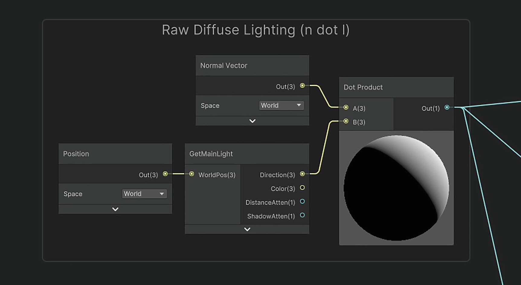
Now let’s carry out the key calculations for this effect, starting with the diffuse light. This comes in two parts. First, we’ll calculate the “raw” diffuse lighting value using the n-dot-l calculation with the help of the GetMainLight subgraph as shown in Figure 14-10. We’ll need the result of this later for both the specular and Fresnel light calculations, because neither of those types of light should appear where diffuse light is absent. The Dot Product node outputs a value between –1 and 1.
A screenshot of the Raw Diffuse Lighting illustrates the process of creation of a dot product with a normal vector and the GetMainLight.
Figure 14-10
The “raw” diffuse calculation, n-dot-l
The second part of the diffuse calculation takes the n-dot-l result and then applies the cutoff, for which we use a Step node. Recall that the Step node returns 1 when its In input is higher than its Edge input and 0 otherwise. After that, we multiply by the light color. This is also a good place to incorporate the ambient light, too, which we can add to the diffuse cutoff result, as shown in Figure 14-11.
A screenshot demonstrates the combination of diffuse cutoff and ambient lighting to create the cel shading graph by a dot product.
Figure 14-11
Adding the cutoff diffuse and ambient light together
Next, let’s calculate the “raw” specular light before any cutoff gets applied. This calculation will look familiar from the PhongShading example. We’ll calculate the half vector by adding the light and view vectors, then normalizing the result, and using it for the specular n-dot-h calculation. We’ll Saturate the result and then raise it to the Gloss Power as shown in Figure 14-12.
A screenshot of the Raw Specular Lighting illustrates the computation of diffuse through the GetMainLight parameters and the normal vector, using the dot product.
Figure 14-12
The “raw” specular calculation, n-dot-h
Next comes the specular lighting cutoff. Before we can do that, multiply the raw specular value by the raw diffuse value, because specular light should never appear where there is no diffuse. I choose to use the pre-cutoff diffuse value so that the specular highlight gradually gets smaller as you approach the cutoff point; otherwise, using the post-cutoff diffuse value results in the specular highlight being cut in half, which looks odd. Use Step to perform the cutoff with Lighting Cutoff once again and then multiply the result by the light color as shown in Figure 14-13.
A screenshot of Specular Cuttoff with a dark circle plot on the right illustrates the multiplication of the raw diffuse and raw specular nodes to determine the specular cutoff.
Figure 14-13
The specular light cutoff calculation. The inputs to the left-hand Multiply node are the results of the raw diffuse and raw specular node groups
The last type of lighting to incorporate is Fresnel. For this, we can use the handy Fresnel Effect node with the Fresnel Power property in its Power input (instead of manually doing the 1-minus-n-dot-v calculation), multiply by the raw diffuse value, and then apply the Fresnel Cutoff with a Step node as shown in Figure 14-14.
A screenshot with a highlighted dark circle plot depicts the multiplication of the Fresnel cutoff and the Fresnel effect to compute the Fresnel power.
Figure 14-14
The Fresnel lighting cutoff calculation
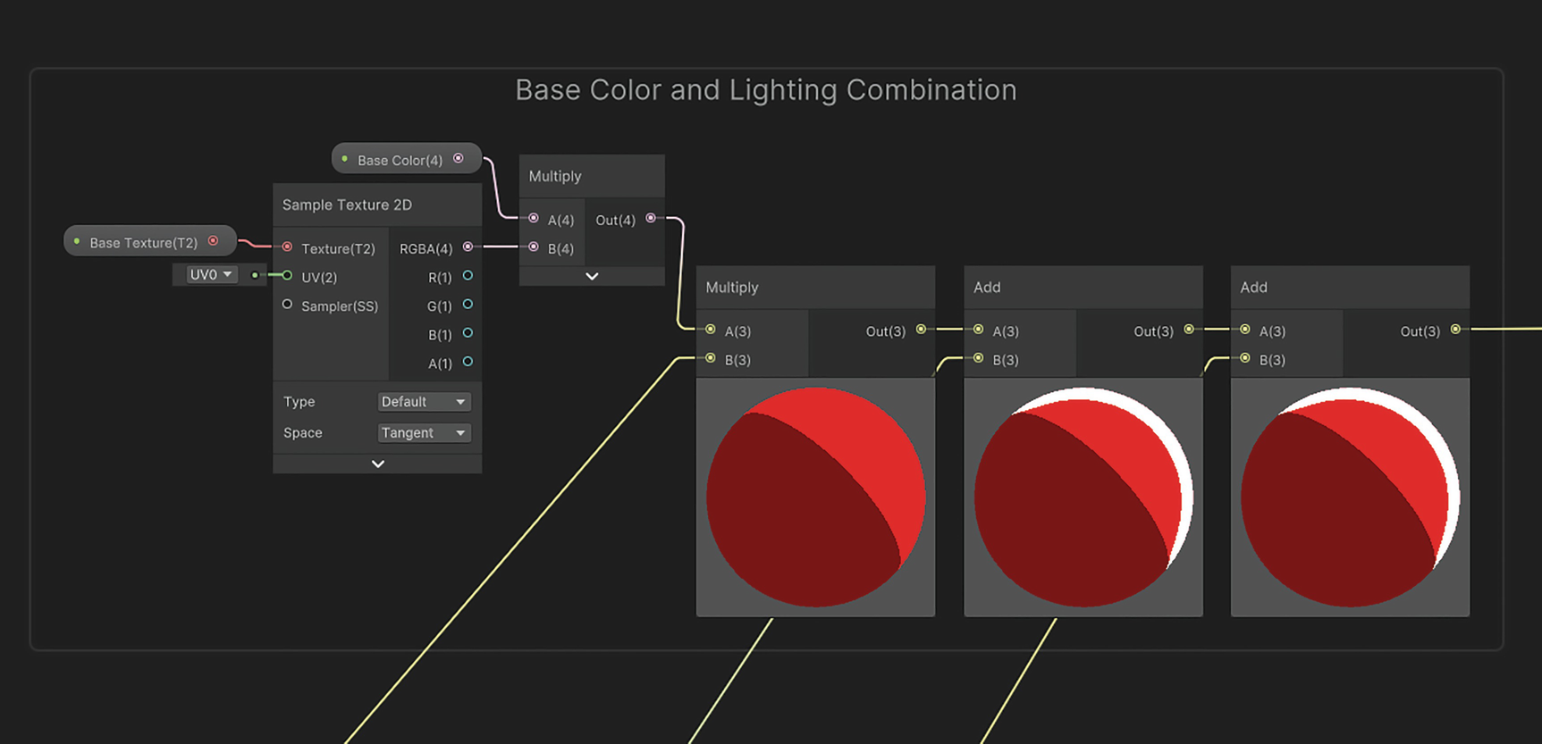
The last step is to tie everything together. Let’s sample the Base Texture and multiply by Base Color and then multiply by the diffuse-plus-ambient value that we calculated earlier. This would give us a matte object. After that, just add the cutoff specular and cutoff Fresnel light values and output the result to the Base Color block on the master stack. Figure 14-15 shows how these nodes should be connected.
A screenshot with the 3 highlighted base color circles depicts the creation of different types of base colors, lighting, and pattern textures in 2 D.
Figure 14-15
Piecing everything together. In this example, I used red for the Base Color to make the different types of lighting easier to see
As with the code version, you can now attach this via a material to any object in your scene, and you should see results like in Figure 14-8. As long as there is at least one light in the scene, you’ll start to see cel-shaded lighting on your objects, thanks to the lighting cutoff point! The cel-shaded aesthetic typically works best on objects without too much texture detail due to the relative simplicity of the lighting, although you may find success with detailed textures if you play around with the effect a little.
In the next example shader, we’ll see a technique that brings together many different shader concepts we’ve seen throughout the book to create a complex interactive effect that can be modified to fit several different aesthetics.
Interactive Snow Layers
Most of the time, you’ll write a shader and attach it to an object, and it’ll just end up as something nice to look at in your game, but that doesn’t have to be the end of the story; shaders can have an interactivecomponent to them. Personally, I enjoy it when games incorporate shaders that you can influence yourself, and in this section, I’ll show you how to make one such shader. If your game has thick layers of snow, then it will feel satisfying for your players if they leave a trail through the snow when walking through it. The same is true for walking through water and leaving ripples in your path or wading through thick liquids like slime or mud or even walking through thick waist-high fog and making the fog dissipate as you fight your way through it, all of which are slightly different takes on the same basic premise. Here’s what my snow implementation looks like.
A capsule shaped collider has left a trail through the snow on a square plot with a snowy effect, and the collider is at the right end.
Figure 14-16
An interactive snow effect. The player (a simple capsule collider) has left a trail through the snow as they walked through it
Tip
It’s very subtle, but I’m using a snow texture from ambientCG on this mesh. The incredibly permissive Creative Commons CC0 license is used for all works on the ambientcg.com website, which allows you to copy, modify, and distribute the work, including for commercial purposes, without requesting permission or giving credit. There are PBR textures available for many common surface types, so you will save a lot of time prototyping with resources from the site.
As you can see, we are using actual mesh deformation for this effect. Consequently, it will have many moving parts. To make sure the ground mesh is sufficiently high resolution to get good-quality trails like these, we will use tessellation to increase the number of vertices in the mesh, since mesh deformation only operates on individual vertices, not fragments. There are several ways we can bake the position of the player and other objects into the heightmap, but I’m going to use a RenderTexture alongside a compute shader to generate the values in that texture. That’s mostly because I find compute shaders extremely powerful and interesting, and I think that seeing them in another context will help you understand just how flexible they can be.
Note
Compute shaders can only be created via code at the moment, and Unity doesn’t seem to have plans for a “Compute Shader Graph.” Furthermore, since we will be using tessellation in the snow mesh shader, we can’t build a Shader Graph version of that shader in URP. However, we can still build the effect in every pipeline by taking a “fully code” approach for the built-in pipeline and URP, and HDRP permits us to use tessellation in Shader Graph.
With this effect, we’ll have a ground mesh that makes up the snow and “actors” that can move around the scene. When one of these actors intersects with the snow, it will displace some amount of the snow. An effect like this is quite tricky to write in a way that generalizes to any shape or size of mesh, whether that’s the ground mesh or the actor mesh, so I’m going to list a few caveats with this specific approach first:
I will assume that the ground mesh is perfectly flat and square. The mesh should also have its local Y facing upward when unrotated. The Unity default plane follows these rules, but the Unity default quad is rotated 90 degrees the wrong way. Meshes that break these rules require rewriting some of the code.
The surface of your mesh should cover the [0,1] UV range exactly. Tiling or offsetting the UVs in any way may break the effect.
The intersection logic relies on colliders, so I will only consider capsule colliders walking through the snow, and I will assume they are oriented standing upward. You can add support for other shapes of collider as an extension, but again, the code will be slightly different.
I also assume that the actors are always taller than the maximum height of the snow. The effect will still work if that’s not true, but the actors will just walk at ground height and delete snow above them, which will probably look strange.
This effect broadly has three parts: the C# scripting side, the compute shader side, and the snow mesh shader side. When using compute shaders, I often find that the C# scripting ends up rather prevalent because there is a lot of setup regarding the data used by the compute shader. With that in mind, we’ll start with the scripting side.
Interactive Snow C# Scripting
We will write two C# scripts, both of which work in each pipeline. One will be relatively short and is attached to each actor in the scene that can interact with the snow, and the other is much longer and is attached to the snow mesh directly. We’ll start with the snow actor script.
The SnowActor C# Script
Start by creating a new C# script and naming it “SnowActor.cs”. The purpose of this script is to provide a way for the snow mesh to get data about actors that are standing in the snow. We’ll be detecting which actors are currently stood in the snow using Unity’s collision system, but the logic for that will be contained entirely within the other C# script attached to the snow mesh. Therefore, the SnowActorclass just needs to expose a few methods to get information about each actor. Here’s the kind of data we’ll need access to:
The “ground position” of the actor, that is, the position of the actor’s “feet.”
The radius of the actor. Remember, we’re just using capsules to represent each actor.
Whether the actor is currently moving. We don’t need to update an actor’s contribution to the snow level if it isn’t currently moving.
Here’s the script in its entirety. We’re not doing anything too fancy here, so it should be straightforward to understand what it’s doing just by reading it.
For the GetRadiusmethod, I’ve added a check so that if you scale along the x- or z-axis, then that gets properly accounted for. All you need to do now is add a default capsule to your scene (Create ➤ 3D Object ➤ Capsule), attach the SnowActor script, and set the groundOffset value to (0, –1, 0), since the midpoint of the capsule is one Unity unit in the air. The capsule primitive already comes with a capsule collider, but Unity only registers collisions if at least one of the parties in the collision has a Rigidbody attached, so go ahead and add one to your capsule. The Rigidbody can be kinematic if you plan to move it using raw code or non-kinematic if you’ll be using forces to move it. However, I’ll leave the movement code out of this example because it’s already very lengthy. Figure 14-17 shows the components attached to the capsule. Let’s move on to the more interesting InteractiveSnow script.
A screenshot of the inspector window lists the options under the Snow Actor with its parameters, script, and ground offset.
Figure 14-17
To register collisions, the snow actor GameObject needs a collider and Rigidbody attached
The InteractiveSnow C# Script
Create another C# script and name it “InteractiveSnow.cs”. The purpose of this script is to set up a texture to keep track of which bits of the snow have been walked on and then handle the compute shader, which will be used to modify that texture. The InteractiveSnow script will keep track of the position of all actors currently inside the snow and then send data to the compute shader to update the texture whenever any of the actors move. Here’s the code we’ll be filling in.
We’ll get into the struct and those methods soon, but first, there are a lot of class variables to get through. Here are the public variables that can be changed in the Inspector:
Snow Resolution – A Vector2Int that stores the resolution of the RenderTexture. A value of about 1024 is plenty for the Unity built-in plane mesh, although you can decrease it to enhance the performance or increase it if you need finer details or if you’re using a larger surface.
Mesh Size – This float is the physical size of the plane in meters. The default value will be 10 since that’s the size of the Unity built-in plane mesh. We use this value to convert the actors’ world-space positions to UV-space positions.
Max Snow Height – This float is the height, in meters, that the snow will reach when the texture is white. This is the starting height of the snow.
Snow Falloff – This float represents the transition between full height and full depression of the snow when an actor walks through it. Without a falloff, the depressions made in the snow would have completely straight vertical walls.
Snow Engulf – Alongside the Snow Falloff, this float artificially reduces the radius of each actor so some of the snow “engulfs” them. This makes the actors look slightly more like the snow is engulfing them.
Max Snow Actors – We must impose a strict limit on the number of snow actors because we will be using fixed-length buffers to send actor data to the compute shader.
Snow Offset Shader – The compute shader itself. We’ll be writing this later.
On top of that, there is a whole host of private variables required to keep track of state and drive the effect:
Snow Offset Tex – This is the RenderTexture that stores the height of each bit of the snow.
Snow Material – This is the material that is attached to the snow mesh. We store a reference to it so that we can bind properties to it during runtime.
Box Collider – We’ll be using Unity’s collision system to detect actors. The snow mesh will have a BoxCollider tagged as a trigger attached for this purpose. The collider will reach from the ground level to the max height of the snow.
Snow Actors – We will keep track of which snow actors are inside the collider via this List.
Snow Actor Buffer – We can’t send the snow actors themselves to the compute shader, and it wouldn’t make much sense to do so because we only need two bits of data: the position and radius of each actor. This GraphicsBuffer will contain that data.
Each of these variables can be included at the top of the script.
public class InteractiveSnow : MonoBehaviour
{
public Vector2Int snowResolution = new Vector2Int(1024, 1024);
public float meshSize = 10.0f;
public float maxSnowHeight = 0.5f;
public float snowFalloff = 0.25f;
public float snowEngulf = 0.1f;
public int maxSnowActors = 20;
public ComputeShader snowOffsetShader;
private RenderTexture snowOffsetTex;
private Material snowMaterial;
private BoxCollider boxCollider;
private List<SnowActor> snowActors = new List<SnowActor>();
private GraphicsBuffer snowActorBuffer;
struct SnowActorInfo { ... }
Listing 14-41
The InteractiveSnow variables
Next, let’s look at the SnowActorInfo struct and the ResetSnowActorBuffer method. We’ll be sending data about each actor to the compute shader, but it’s not possible to send a reference to the entire GameObject. Nor would that make any sense, because we only need the position and radius of each of those actors. Instead, we’ll use this struct. Every time we want to send actor data to the GPU, we’ll build an instance of this struct for each actor and package them inside the snowActorBuffer. We do that inside the ResetSnowActorBuffer method, which iterates through the actor list, checks the actor is moving, then calculates its position and radius in UV space, and creates the struct.
struct SnowActorInfo
{
public Vector3 position;
public float radius;
}
Listing 14-42
The SnowActorInfo struct
private void ResetSnowActorBuffer()
{
var snowActorInfoList = new SnowActorInfo[snowActors.Count];
Here, the InverseTransformPoint method transforms the actor position to the snow mesh’s local space. Only actors that are moving and are positioned above the mesh get included in the buffer. From there, we divide the x- and z- components by meshSize to transform the position to snowOffsetTex’s UV space and divide the y-component by the maxSnowHeight – we’ll be using that value to determine the snow’s new height at this position. We’ll need to add an offset of 0.5 along the x- and z-directions because the snow mesh center point was misaligned with the UV coordinate origin point.
Now we’ll fill in the OnTriggerEnter, OnTriggerExit, and OnDestroy methods. The first two of those methods register and deregister instances of SnowActor whenever they enter and exit the trigger, respectively. The OnDestroy method exists to clean up the snowActorBuffer when we don’t need it anymore.
The OnTriggerEnter, OnTriggerExit, and OnDestroy methods
Let’s now explore the Start method, which is the longest one in the file. This method is responsible for setting up the many moving parts of the effect and setting the initial state of the shaders. Here’s what the code will do, in order:
Create the snowOffsetTex texture. It is crucial to enable reading and writing the texture so that we are able to update it whenever actors interact with the snow.
Get references to the BoxCollider component and the material attached to the snow mesh’s Renderer component.
Resize the box collider and reposition its center point accordingly. The bottom face of the collider intersects the ground level, and the top face intersects the max snow level.
Create the GraphicsBuffer that will be used to hold actor data for the compute shader.
Set properties on both the compute shader and the regular shader that do not need updating at runtime.
Run a kernel on the compute shader called “InitializeOffsets”. This kernel sets the initial color values of snowOffsetTex.
private void Start()
{
snowOffsetTex = new RenderTexture(snowResolution.x, snowResolution.y, 0, RenderTextureFormat.ARGBFloat);
snowOffsetTex.enableRandomWrite = true;
snowOffsetTex.Create();
snowMaterial = GetComponent<Renderer>().material;
boxCollider = GetComponent<BoxCollider>();
Vector3 size = boxCollider.size;
size.y = maxSnowHeight;
boxCollider.size = size;
Vector3 center = boxCollider.center;
center.y = maxSnowHeight / 2.0f;
boxCollider.center = center;
snowActorBuffer = new GraphicsBuffer(GraphicsBuffer.Target.Structured, maxSnowActors, sizeof(int) * 4);
That leaves just the Update method to fill in. This method first checks if there are any actors inside the snow actor list, and if not, then the Update method returns immediately to avoid unnecessary computation. If there are, then it updates the snow actor buffer. Then it finds the “ApplyOffsets” kernel; sends the actor buffer and offset texture to that kernel, as well as the number of snow actors; and finally dispatches the kernel. This kernel is the most important one in the entire effect, as it displaces the snow height at each actor position.
private void Update()
{
if (snowActors.Count == 0)
{
return;
}
ResetSnowActorBuffer();
int kernel = snowOffsetShader.FindKernel("ApplyOffsets");
This script is now complete. To set up the snow mesh, attach the InteractiveSnow script to it and ensure it has a box collider attached with the Is Trigger option ticked. You can add other colliders to the mesh to avoid objects clipping through the floor – in Figure 14-18, I’ve also attached a mesh collider – but make sure there is only one box collider, because we’re modifying its size via scripting.
A screenshot of the inspector window lists the options under Snow Mesh with transform, plane, mesh renderer, interactive snow script, box collider, and mesh collider.
Figure 14-18
Components attached to the snow mesh. We haven’t yet written the InteractiveSnow shader that will be attached to the material
It’s time to write the compute shader that will update the snow offset texture each frame.
Interactive Snow Compute Shader
The compute shader includes two kernels. One is used to set the original snow level, and the other is used to apply the influence of the snow actors to modify the snow level. Start by creating a new compute shader via Create ➤ Shader ➤ Compute Shader and naming it “InteractiveSnow.compute”. Here’s the code we’ll start with.
#pragma kernel InitializeOffsets;
#pragma kernel ApplyOffsets
struct SnowActorInfo { ... };
RWTexture2D<float4> _SnowOffset;
uniform float2 _SnowResolution;
uniform float _SnowFalloff;
StructuredBuffer<SnowActorInfo> _SnowActors;
uniform int _SnowActorCount;
[numthreads(8,8,1)]
void InitializeOffsets(uint3 id : SV_DispatchThreadID) { ... }
float inverseLerp(float a, float b, float t)
{
return (t - a) / (b - a);
}
[numthreads(8,8,1)]
void ApplyOffsets (uint3 id : SV_DispatchThreadID) { ... }
Listing 14-47
The InteractiveSnow compute shader code skeleton
First, let’s set up the SnowActorInfo struct. The members of this struct should match up with the members of the corresponding SnowActorInfo struct that we wrote in the C# script, except instead of using C# variable types, we use HLSL variable types.
struct SnowActorInfo
{
float3 position;
float radius;
};
Listing 14-48
The SnowActorInfo struct
It is possible to mix and match regular functions and multiple kernel functions inside a single compute shader file, so we specify the kernel functions using the #pragma kernel statement. You’ll notice that the variables inside this file are direct parallels of those from the InteractiveSnow script – these are the exact variables we sent data to from within that script. We’ve encountered StructuredBuffer previously, so the other variable type of note is RWTexture2D, which is just a rewritable and readable variant of the standard Texture2D.
The first kernel function is called InitializeOffsets. This kernel function runs over each texel of the texture once, so if the texture has a resolution of 1024 by 1024, then the thread ID will run from 1 to 1024 in the x- and y-directions. All we do in this function is set every entry in the texture to white, or 1. Although this is perhaps a bit overkill, this leaves room for you to tweak the initial offset values if you’d like.
[numthreads(8,8,1)]
void InitializeOffsets(uint3 id : SV_DispatchThreadID)
{
_SnowOffset[id.xy] = 1.0f;
}
Listing 14-49
The InitializeOffsets kernel function
The second kernel function is called ApplyOffsets. In this function, we’ll iterate over the _SnowActors list, and for each one, we will compute the distance of the actor from the UV position of the texel associated with the thread. If that distance is less than the radius plus falloff, then we can modify the height of the snow and store the new value in the _SnowOffset texture.
Here, the inverseLerp function will help. Where lerp takes two input values and returns a new “result” value between them based on the third input value called the interpolation factor, the inverseLerp function takes two input values and a “result” value and returns what interpolation factor would have returned that “result” value in a lerp. That’s why it’s the “inverse” of lerp!
[numthreads(8,8,1)]
void ApplyOffsets (uint3 id : SV_DispatchThreadID)
This compute shader is now complete. The two kernels are called from the InteractiveSnow C# script, as you saw. Whenever the compute shader makes a change to the snow offset texture, those changes can also be seen by any other shader that references that texture. In that same C# script, we already bound that texture to the snow mesh’s material, so the final step is to see how that material’s shader works.
Interactive Snow Mesh Shader
This shader works by displacing the vertices of the mesh in the y-direction according to the value in the snow offset texture. To draw snow trails in the ground, the mesh needs to have a sufficiently high vertex resolution, so we will use tessellation in the shader to achieve that. That causes a couple of issues that we covered in Chapter 12. Recall that in Shader Graph, only HDRP supports tessellation – URP does not. However, both the built-in pipeline and URP can support tessellation with code-based shaders, so you’re not completely out of luck in URP! I’ll show you how to write the shader in HLSL and then in Shader Graph.
Snow Shader in HLSL
Start by creating a new shader file and naming it “InteractiveSnow.shader”. Although we’ve named several files for this effect “InteractiveSnow”, the file extensions are all different, so don’t worry about conflicts arising from that. As I mentioned, we’ll be using tessellation for this effect, but we won’t be doing anything regarding tessellation that we didn’t already see in Chapter 12, so I won’t explain it in detail here. With that in mind, here’s the code we’ll be starting with.
Shader "Examples/InteractiveSnow"
{
Properties { ... }
SubShader
{
Tags
{
"RenderType" = "Opaque"
"Queue" = "Geometry"
}
Pass
{
HLSLPROGRAM
#pragma vertex vert
#pragma fragment frag
#pragma hull tessHull
#pragma domain tessDomain
#pragma target 4.6
...
struct appdata
{
float4 positionOS : Position;
float2 uv : TEXCOORD0;
};
struct tessControlPoint
{
float4 positionOS : INTERNALTESSPOS;
float2 uv : TEXCOORD0;
};
struct tessFactors
{
float edge[3] : SV_TessFactor;
float inside : SV_InsideTessFactor;
};
struct v2f
{
float4 positionCS : SV_Position;
float2 uv : TEXCOORD0;
};
...
tessControlPoint vert(appdata v) { ... }
v2f tessVert(appdata v) { ... }
tessFactors patchConstantFunc( ... ) { ... }
tessControlPoint tessHull( ... ) { ... }
v2f tessDomain( ... ) { ... }
float4 frag (v2f i) : SV_Target { ... }
ENDHLSL
}
}
Fallback Off
}
Listing 14-51
The InteractiveSnow mesh shader skeleton
First, let’s deal with tags and include files, which are different between the built-in pipeline and URP.
Pass
{
Tags
{
"LightMode" = "ForwardBase"
}
HLSLPROGRAM
#pragma vertex vert
#pragma fragment frag
#pragma hull tessHull
#pragma domain tessDomain
#pragma target 4.6
#include "UnityCG.cginc"
Listing 14-52
Tags and include files for the snow effect in the built-in pipeline
Next, we will add the shader properties, of which some we have seen briefly before in the C# script and others were present in the compute shader. Here’s what each property will do:
Low Color – The Color assigned to parts of the snow mesh that have been fully stood on.
High Color – The Color shown on the parts of the snow at the maximum height. These two colors will both use the [HDR] attribute, which is particularly important on the high color where the snow will be brightest, as snow tends to brightly reflect the sun and we can artificially boost the brightness using HDR.
Base Tex – The albedo Texture for the snow surface.
Snow Offset – The Texture containing the offset at each point on the snow’s surface. This is the same texture that was generated by the compute shader.
Max Snow Height – The maximum height that the snow will be offset by in world space along the y-axis.
Tess Amount – The number of tessellation subdivisions applied to the mesh. The hardware maximum value is 64.
We must declare these in the Properties block in all pipelines using ShaderLab syntax.
Declaring properties for the snow effect in the Properties block
After, we must then redeclare them in the HLSLPROGRAM block, which requires slightly different code between the built-in pipeline and URP. These declarations can go beneath the v2f struct definition.
struct v2f { ... };
sampler2D _BaseTex;
sampler2D _SnowOffset;
float4 _LowColor;
float4 _HighColor;
float _MaxSnowHeight;
float _TessAmount;
Listing 14-55
Declaring properties in HLSLPROGRAM in the built-in pipeline
struct v2f { ... };
sampler2D _BaseTex;
sampler2D _SnowOffset;
CBUFFER_START(UnityPerMaterial)
float4 _LowColor;
float4 _HighColor;
float _MaxSnowHeight;
float _TessAmount;
CBUFFER_END
Listing 14-56
Declaring properties in HLSLPROGRAM in URP
For the rest of the shader, the code is identical between the two pipelines. First, let’s deal with the tessellation-specific code. As I mentioned, nothing here will look any different from what we learned about tessellation in Chapter 12. To recap
The vertex function, vert, converts instances of appdata into tessControlPoint instances.
Then, the hull shader function, tessHull, and patch control function, patchConstantFunc, are responsible for positioning the input control points and supplying tessellation factors, respectively; both these stages happen in parallel.
Then, the tessellator (which is not a programmable stage) creates the new control points, which get fed to the domain shader function, tessDomain.
The tessDomain function interpolates properties about the new control points between the old control points.
The vertex shader and tessellation-specific functions
That leaves us with only the tessVert and frag functions. Although this shader officially uses vert as its vertex function, the only purpose of that is to funnel data to the tessellation stages. We’ll run the tessVert function on the outputs from tessDomain, so it acts like a post-tessellation vertex shader. For this function, we can sample _SnowOffset with tex2Dlod to obtain the normalized height for the current vertex. Recall that in the vertex stage, we must specifically use tex2Dlod, as the regular tex2D function won’t work. We’ll use the height value to apply a world-space offset in the y-direction, capped at _MaxSnowHeight. After that, we’ll convert from world space to clip space and output a v2f instance, outputting the same UVs that were input.
Finally, we come to the frag function, which is run last in the graphics pipeline. By sampling the same _SnowOffset texture as the tessVert function (this time using tex2D), we can lerp between _LowColor and _HighColor to calculate a tint color based on the strength of the snow depression at the current position. We then sample _BaseTex to obtain the snow’s albedo color and multiply by the tint color to get our shader output.
This shader is now finished, so you can attach it to a material and apply it to the snow mesh GameObject. If the InteractiveSnow and SnowActor scripts are correctly applied to objects in the scene, then you will see results like in Figure 14-16 if you run the game in Play Mode. If you are using HDRP, then you’ll need to write this shader in Shader Graph instead, which we’ll cover next.
Snow Shader in Shader Graph
Start by creating a new Unlit graph and name it “InteractiveSnow.shadergraph”. Open it in the Shader Grapheditor, and in the Graph Settings, expand the Surface Options section and tick Tessellation. You should see the Tessellation Factor and Tessellation Displacement blocks appear on the vertex stage of the master stack, which we will need soon. Before we can use them, we’ll need to add some shader properties.
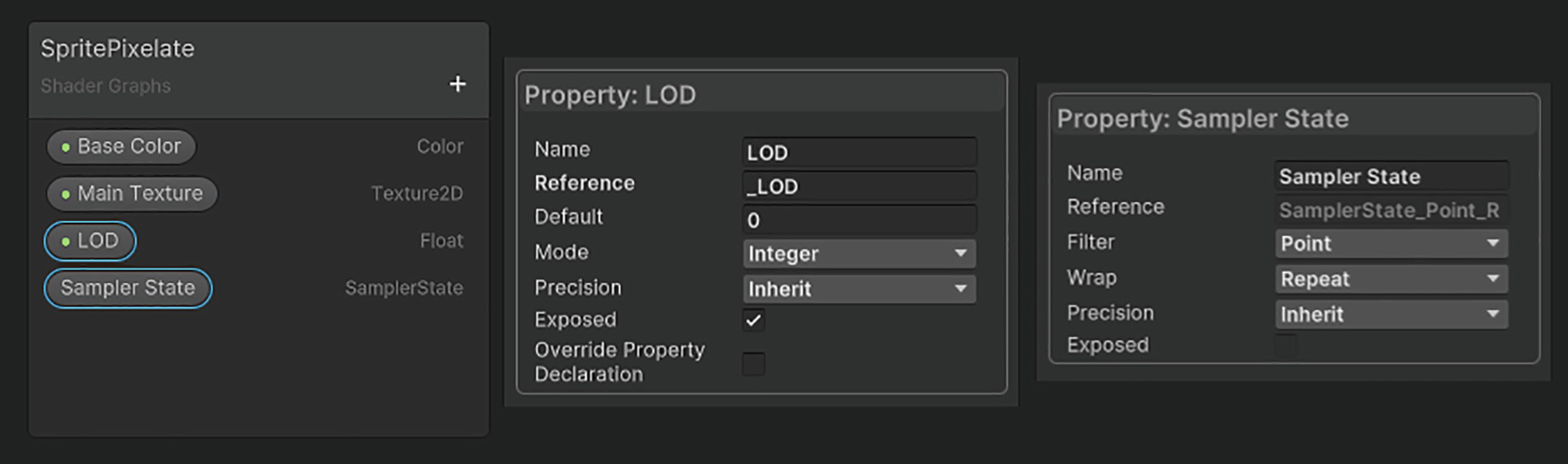
The properties for this graph will be the same as in the HLSL version of the shader – each one is described in that section. Figure 14-19 shows the properties required for this graph, particularly the _LowColor, _HighColor, and _TessAmount properties that use special settings.
A screenshot of the interactive snow window depicts 6 properties: low color, high color, base tex, snow offset, max snow height, and tess amount.
Figure 14-19
The InteractiveSnow graph properties
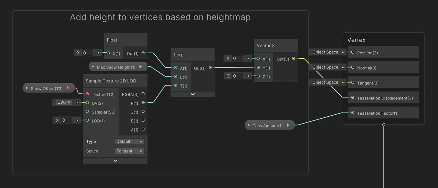
With the properties in place, let’s tessellate the mesh and apply an offset to each vertex of the mesh along the y-axis according to the values in the Snow Offset texture. For that, we must use the Sample Texture 2D LOD node, because the standard Sample Texture 2D node does not work in the vertex stage. The values from the texture are between 0 and 1, so we will use a Lerp node to change the range to between 0 and Max Snow Height. We’ll use a Vector 3 node to construct the offset vector and output it to the Tessellation Displacement block on the master stack. For the Tessellation Factor block, we’ll connect our Tess Amount property as shown in Figure 14-20.
A screenshot of the add height to vertices based on the heightmap illustrates the output of the snow offset from the float, max snow height, and tessellation factor.
Figure 14-20
Applying a height offset to the vertices of the tessellated mesh
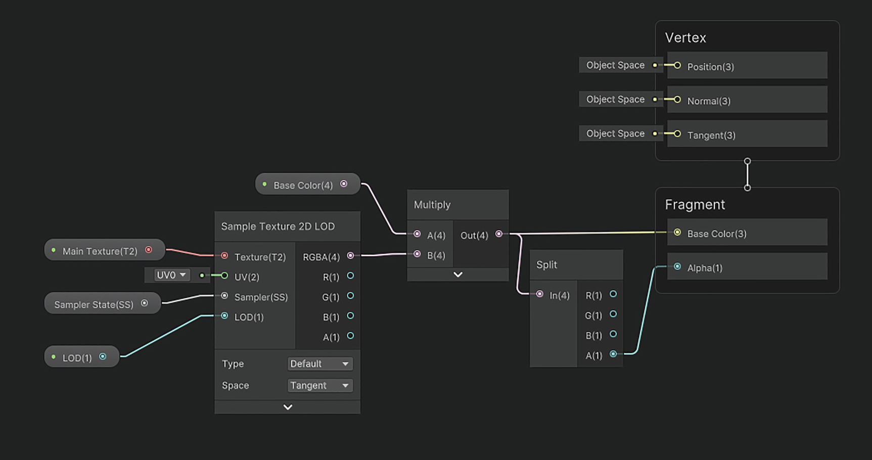
Unity will then handle the tessellation for us – we won’t need to tweak any of the default tessellation settings in the Graph Settings window. We can now move to the fragment stage of the graph. In this stage, we will sample the Snow Offset texture and use the result – a value between 0 and 1 – as the interpolation factor of a Lerp node to pick between Low Color (when the value is 0) and High Color (when the value is 1). Then, we’ll multiply it by the albedo color, which we get by sampling Base Tex. The result is used for the Base Color output of the graph. Figure 14-21 shows how these nodes should be connected.
A screenshot of color fragments based on the heightmap illustrates the output of snow offset from the sample texture 2 D and base tex.
Figure 14-21
Determining the snow tint color that influences the albedo color
This graph is now complete, so you can use it in a material and attach the material to the snow mesh. If you’ve set everything else up as I described, then you will be able to move a snow actor through the trigger attached to the mesh, and trails will start to appear in the snow as the actor walks through it, as seen in Figure 14-16.
Although interactive shader effects are exciting, it can be just as exciting to make pretty shaders that the player can’t interact with, so next, we’ll create a hologram shader that can be used to visually enhance games with a futuristic setting.
Holograms
A surefire way to make your game look more futuristic is to add holograms to it. Holograms are essentially a projection of a mesh into the world using bright light, so typically, holograms in games give off a soft colorful glow. Although there are several different directions you could go in, I’ll make a hologram effect by supplying a black and white texture that encodes which parts of the mesh should be cut out. The idea is if you want a hologram that looks like scan lines, then you can supply a texture full of alternating black and white lines and if you want a hologram that looks speckled like white noise, then you can supply a texture made up of scattered white dots on a black background. The texture will be sampled in screen space. Then we’ll apply an HDR color to the white parts and cull the black parts. Figure 14-22 shows you the kinds of effect you can make using this approach.
A quintet of spheres placed side by side illustrates the hologram effect on the color and texture of spheres. Each sphere is shaded with a different color.
Figure 14-22
Five holograms with different hologram textures and colors. This effect looks best when viewing the effects at native resolution, as resizing can impact the sampling
One key thing to keep in mind is that you must have a bloom filter attached to your camera to see the color bleeding present in Figure 14-22 – this effect is available in each pipeline’s built-in post-process effect stack. We’ll be making this effect in both HLSL and Shader Graph.
Holograms in HLSL
Start by creating a new shader and naming it “Hologram.shader”. We’ll be using alpha testing to cull the gaps between the holographic pixels, so make sure the Queue tag for this shader is set to AlphaTest. Here’s the code we’ll be starting with.
Shader "Examples/Hologram"
{
Properties { ... }
SubShader
{
Tags
{
"RenderType" = "Opaque"
"Queue" = "AlphaTest"
}
Pass
{
Tags
{
"LightMode" = "UniversalForward"
}
HLSLPROGRAM
#pragma vertex vert
#pragma fragment frag
struct appdata
{
float4 positionOS : Position;
float2 uv : TEXCOORD0;
};
struct v2f { ... };
v2f vert (appdata v) { ... }
float4 frag (v2f i) : SV_Target { ... }
ENDHLSL
}
}
Fallback Off
}
Listing 14-60
The Hologram shader code skeleton
The first addition we’ll make is to add the correct tags and include files for the pipeline you are using. This code should be familiar to you by now!
Pass
{
Tags
{
"LightMode" = "ForwardBase"
}
HLSLPROGRAM
pragma vertex vert
#pragma fragment frag
#UnityCG.cginc"
Listing 14-61
Tags and include files for the hologram effect in the built-in pipeline
Tags and include files for the hologram effect in URP
Next, let’s deal with the shader properties. I briefly described what kind of data the shader requires in the introduction to this shader, but let’s go into more detail here:
Base Tex – The albedo texture that would usually be applied to an object. If this texture has fully transparent portions, then this will be important when we cull pixels later.
Hologram Tex – A texture that should contain only black and white. We’ll sample this texture in screen space, take only the red channel, and use it as a “mask” to determine which areas of the object should emit glowing light and which areas should be culled.
Hologram Color – A tint color applied to the holographic pixels. This is an HDR color, which facilitates the glowing effect.
Hologram Size – This float is used to scale the hologram texture.
We’ll need to declare each of these properties in the Properties block.
Declaring properties for the hologram effect in the Properties block
We’ll need to then declare them once more in the HLSLPROGRAM block, where the code is slightly different depending on the pipeline you are using. We’ll declare each of these properties underneath the v2f struct definition. I’m going to be using the texel size of _HologramTex in a later step, so we need to include the _HologramTex_TexelSize variable here too.
struct v2f { ... };
sampler2D _BaseTex;
sampler2D _HologramTex;
float4 _BaseTex_ST;
float4 _HologramTex_TexelSize;
float4 _HologramColor;
float _HologramSize;
Listing 14-64
Declaring properties in the HLSLPROGRAM block for the hologram effect in the built-in pipeline
struct v2f { ... };
sampler2D _BaseTex;
sampler2D _HologramTex;
CBUFFER_START(UnityPerMaterial)
float4 _BaseTex_ST;
float4 _HologramTex_TexelSize;
float4 _HologramColor;
float _HologramSize;
CBUFFER_END
Listing 14-65
Declaring properties in the HLSLPROGRAM block for the hologram effect in URP
Next, let’s look at the v2f struct itself. Most basic shaders like this one don’t need anything inside the v2f struct besides clip-space positions and UV coordinates, but as I mentioned, I want to sample _HologramTex in screen space. Therefore, we require screen-space coordinates for use in the fragment shader. For that, we can calculate them in the vertex shader and send them to the fragment shader via the v2f struct. I’ll name the variable positionSS, to fit our naming scheme, and use the TEXCOORD1 semantic for it.
struct v2f
{
float4 positionCS : SV_Position;
float2 uv : TEXCOORD0;
float4 positionSS : TEXCOORD1;
};
Listing 14-66
The v2f struct
Now we can move on to the vert function, that is, the vertex shader, where we will calculate the value of positionSS, as well as everything else that needs to go in the v2f struct. We’ve seen how to calculate positionCS and uv before – the calculation for positionCS requires pipeline-specific code. To calculate positionSS, we can use the ComputeScreenPos function, which is included in all pipelines; this function takes the clip-space position as a parameter and returns the screen-space position.
The shader is now complete, so you should be able to see objects like those in Figure 14-22 if you create a material with this shader and attach it to objects in your scene. Let’s see how this effect works in Shader Graph too.
Holograms in Shader Graph
Start by creating a new Unlit graph and naming it “Hologram.shadergraph”. Start by going into the Graph Settings and ticking the Alpha Clipping setting – besides doing that, you can keep using Opaque rendering. The properties we’ll need for this graph are the same as the ones we used in the HLSL version of the effect, so check out that section for a full description of each property. Figure 14-23 lists the properties we need and their types.
A screenshot of the hologram dialog box lists the following properties: base texture, hologram color, hologram texture, and hologram size.
Figure 14-23
The properties for the Hologram effect
On the graph itself, the first thing we need to do is calculate the screen-space UVs with which we’ll sample the Hologram Texture. This is a little easier to do in Shader Graph than in HLSL code because Shader Graph comes with a Screen Position node that we can use. Multiply that by the screen resolution to obtain a position in what I like to call “pixel space.” Then, multiply the Hologram Texture’s Texel Size by the Hologram Size, and use that value to divide the pixel-space position. Figure 14-24 shows how these nodes should be connected.
A screenshot illustrates the calculation of the screen space hologram U V by sampling the screen position, hologram size, and hologram texture.
Figure 14-24
Calculating the UVs for sampling the Hologram Texture
Finally, we can sample the Hologram Texture using these screen-space UVs. Also sample the Base Texture using the standard set of UVs. For the Base Color output on the master stack, take the hologram sample’s R component, multiply by Hologram Color, and add the base sample color. For the Alpha output on the master stack, simply add the R component of the hologram sample to the A component of the base sample. Connect these nodes as shown in Figure 14-25.
A screenshot of the shader graph illustrates the result of the output graph with hologram texture and hologram color to base texture sample.
Figure 14-25
Using the Hologram Texture and Base Texture for the graph outputs
With that, the effect is complete! Attach this shader to a material and use it on objects in your scene to make them glow, as shown in Figure 14-22. As I mentioned, there are so many ways you can build a holographic effect, so try swapping out the hologram texture with all kinds of patterns to see how they affect the outcome. You could also try sampling the hologram texture in world space or object space instead of screen space, which produces rather different results, or try animating the hologram texture over time. There’s really no limit to futuristic holograms! In the next section, we’ll be building a couple of shaders specifically for 2D sprites.
Sprite Effects
So far in the book, we have focused almost entirely on 3D objects. While a lot of the concepts can be translated to 2D and several of the shaders will still work on 2D objects with some modification, I want to focus on some 2D effects in this section. To round off the book, we’ll create a few fun effects that make your sprites look snazzy!
Each of these effects will be built with the default Sprite Renderer in mind. The Sprite Renderer has two fields we are primarily interested in: the Sprite field and the Material field. When we attach a material to this Sprite Renderer, then whichever sprite is attached to the Sprite field will automatically get sent to the shader the material uses in the _MainTex slot. Therefore, it is important to base our shaders on that _MainTex texture. With that in mind, let’s move on to the first effect.
Sprite Pixelation
Let’s start off simple to get the hang of sprite-specific shaders. With this effect, we will introduce the ability to pixelate a sprite based on a slider value, as seen in Figure 14-26.
Five pictures of an animated man depict the pixel size of the animated man increasing from left to right and from low level to high level.
Figure 14-26
The same sprite shown five times, with increasingly higher levels of pixelation as you go from left to right
Note
The sprites I’ll be using in this section are by Kenney. These Creative Commons CC0 assets and many more can be found at kenney.nl/assets.
There’s one important thing you must do on all sprites you want to use with this effect. In the import settings for the original texture, make sure that Generate Mip Maps is ticked – the option is about halfway down the list of settings. Once you’ve done that, we can move on to writing the shader – we’ll cover the effect in HLSL code and then in Shader Graph.
Sprite Pixelation in HLSL
Start by creating a new shader and naming it “SpritePixelate.shader”. This will be a basic vertex-fragment shader, so here’s the code we’ll be starting with.
Shader "Examples/SpritePixelate"
{
Properties { ... }
SubShader
{
Tags
{
"RenderType" = "Transparent"
"Queue" = "Transparent"
}
Pass
{
Cull Off
Blend SrcAlpha OneMinusSrcAlpha
ZTest LEqual
ZWrite Off
HLSLPROGRAM
#pragma vertex vert
#pragma fragment frag
struct appdata
{
float4 positionOS : Position;
float2 uv : TEXCOORD0;
};
struct v2f
{
float4 positionCS : SV_Position;
float2 uv : TEXCOORD0;
};
v2f vert (appdata v) { ... }
float4 frag (v2f i) : SV_Target { ... }
ENDHLSL
}
}
Fallback Off
}
Listing 14-70
The SpritePixelate shader code skeleton
Sprite shaders typically use transparent rendering with two-sided rendering, so I’ve set up the shader tags appropriately and added the correct Blend, Cull, ZTest, and ZWrite keywords. Next, let’s set up include files and other tags, which are required in each pipeline. This code is probably second nature to you by now!
Pass
{
Tags
{
"LightMode" = "ForwardBase"
}
Cull Off
Blend SrcAlpha OneMinusSrcAlpha
ZTest LEqual
ZWrite Off
HLSLPROGRAM
#pragma vertex vert
#pragma fragment frag
#include "UnityCG.cginc"
Listing 14-71
Tags and include files for the sprite pixelation effect in the built-in pipeline
Tags and include files for the sprite pixelation effect in URP
Next, let’s add the shader properties. For this shader, instead of using _BaseTex as our name for the base texture as we usually do, we will instead use _MainTex, because Unity automatically binds this name to the sprite attached to the Sprite Renderer. Additionally, I will include a _BaseColor property to tint the texture and an _LOD property to control the level of pixelation seen on the sprite.
Properties
{
_BaseColor ("Base Color", Color) = (1, 1, 1, 1)
_MainTex("Main Texture", 2D) = "white" {}
_LOD("LOD", Int) = 0
}
Listing 14-73
Adding properties to the Properties block for the sprite pixelation effect
As usual, we must also declare these properties inside the HLSLPROGRAM code block. However, we’ll be doing something slightly different with _MainTex. In Chapter 5, I gave an overview of how custom SamplerState objects can be added to shaders, and here we have a prime example of where to use them, because I want to force the sprite to use blocky pixel rendering, rather than bilinear filtering. To use a custom SamplerState to sample the texture, we need to use the Texture2D type and declare a new SamplerState separately rather than using the sampler2D type we’re accustomed to. The name of the SamplerState will be sampler_point_repeat, which Unity will automatically interpret to mean “point sampling, repeat wrapping.” We can declare these, alongside the other properties, underneath the v2f struct definition.
struct v2f { ... };
Texture2D _MainTex;
SamplerState sampler_point_repeat;
float4 _BaseColor;
float4 _MainTex_ST;
int _LOD;
Listing 14-74
Declaring the properties in HLSLPROGRAM in the built-in pipeline
struct v2f { ... };
Texture2D _MainTex;
SamplerState sampler_point_repeat;
CBUFFER_START(UnityPerMaterial)
float4 _BaseColor;
float4 _MainTex_ST;
int _LOD;
CBUFFER_END
Listing 14-75
Declaring the properties in HLSLPROGRAM in URP
Now we come to the vertex shader, vert. This vertex function is just like any other – just because we’re using a sprite doesn’t mean it is special. Unity automatically generates a mesh to fit your sprite, so we can use UnityObjectToClipPos in the built-in pipeline or TransformObjectToHClip in URP to transform vertex positions from object space to clip space and TRANSFORM_TEX in both pipelines to account for UV tiling and offset settings on _MainTex.
The vert function for the sprite pixelation effect in URP
That leaves us with the fragment shader, frag. Recall from Chapter 5 that you can sample a texture using the Sample function rather than the tex2D function; there is another function, SampleLevel, that allows you to sample the texture with a specific mip level. We’ll use that to sample _MainTex and then multiply the result by _BaseColor.
This code works in both the built-in and Universal pipelines, so we’re now done with the shader, and you’ll be able to see results like in Figure 14-26 if you use this shader with a sprite. Let’s cover the effect in Shader Graph next.
Sprite Pixelation in Shader Graph
Start by creating a new graph and naming it “SpritePixelate.shadergraph”. Here, your choice of graph type depends on which render pipeline you are using. In URP, rather than using the standard Unlit type that we’ve used previously for 3D objects, you can use the Sprite Unlit type instead. This type of graph automatically uses transparent, double-sided rendering. In HDRP, there is no such graph type, so we’ll have to make do with the Unlit type. You’ll have to manually change the Surface Type to Transparent and tick the Double-Sided option in the Graph Settings too. With these settings, both pipelines will have the same blocks on the master stack (except HDRP will have an additional Emission block, which we can ignore). Once you’ve sorted the graph type out, we can move on to the shader properties.
We will use the same three properties as the HLSL version of the effect, plus one extra, as detailed in Figure 14-27:
A Color called Base Color. The default value should be white with full alpha.
A Texture2D called Main Texture. You must set the reference value to _MainTex to ensure Unity automatically binds the sprite attached to the Sprite Renderer to this texture slot.
A Float called LOD. We can set this property’s Mode to Integer.
A SamplerState, which we can just name Sampler State. The Filter mode should be set to Point, and the Wrap mode should be Repeat. This property is unable to be exposed to the Inspector, so think of it as a “local variable.”
A screenshot of the sprite pixelate lists 4 properties: Base Color, Main Texture, L O D, and Sampler. The parameters of L O D, and Sampler are visible.
Figure 14-27
Properties for the SpritePixelate effect. The LOD and Sampler State properties are highlighted as we must change a couple of settings on them
The surface of the graph itself is incredibly simple. We’ll use a Sample Texture 2D LOD node with the Main Texture property in its Texture slot, the LOD property in its LOD slot, and the Sampler State property in its Sampler slot. We can then multiply the RGBA output by Base Color, output the full result to the Base Color block on the master stack, then separate out the alpha with a Split node, and output that to the Alpha output on the master stack, as shown in Figure 14-28.
A screenshot of the shader graph illustrates the creation of the Sprite Pixelate graph surface through the base color, main texture, sampler state, and L O D.
Figure 14-28
The SpritePixelate graph surface
With that, the shader is complete, and you can now use this effect in every pipeline and get results like in Figure 14-26. Although you could use this shader for purely utilitarian reasons, I said we would be making fun shaders in this section, so I like to use effects like this one to fade out sprites in a sort of “pixelated explosion” effect by increasing the LOD setting while decreasing the alpha component of Base Color. It makes things look a lot more interesting than just an alpha falloff! Now let’s see how another sprite-based effect works.
Sprite Ripples
For this effect, we’ll modify the UVs to make the sprite appear as if ripples emanated from the center outward. To do this, we will measure the distance of each pixel from the center of the sprite, create a clock, and then feed both values into a sine function. Based on the result, which should give us a radial pattern, we’ll add a UV offset and sample _MainTex, resulting in the effect shown in Figure 14-29.
Let’s build this effect in HLSL code and then in Shader Graph.
Five pictures of an animated man illustrate the changes in an animated man's facial features: outward expansion with inward contraction later.
Figure 14-29
From left to right, the ripples distort the sprite over time. The effect is far more evident in motion, but it’s easiest to see on the face here, as the facial features expand outward and then contract inward
Sprite Ripples in HLSL
Start by creating a new shader file called “SpriteRipples.shader”. Here’s the code we will start out with.
Shader "Examples/SpriteRipples"
{
Properties { ... }
SubShader
{
Tags
{
"RenderType" = "Transparent"
"Queue" = "Transparent"
}
Pass
{
Cull Off
Blend SrcAlpha OneMinusSrcAlpha
ZTest LEqual
ZWrite Off
HLSLPROGRAM
#pragma vertex vert
#pragma fragment frag
struct appdata
{
float4 positionOS : Position;
float2 uv : TEXCOORD0;
};
struct v2f
{
float4 positionCS : SV_Position;
float2 uv : TEXCOORD0;
};
v2f vert (appdata v) { ... }
float4 frag (v2f i) : SV_Target { ... }
ENDHLSL
}
}
Fallback Off
}
Listing 14-79
The SpriteRipples shader code skeleton
First, we need to add the appropriate tags and include files for the pipeline you’re working in. If you are using the built-in pipeline, add the code from Listing 14-71, or if you’re working in URP, add the code from Listing 14-72. Similarly, the vertex shader is the same as the SpritePixelate shader example, but it differs between pipelines, so add the vert function from Listing 14-76 if you are working in the built-in pipeline or from Listing 14-77 if you are working in URP.
Next, let’s deal with the shader properties. Alongside the _MainTex property that we must include to have access to the sprite attached to the Sprite Renderer and the _BaseColor property we include in most of our shaders, we’ll also add three properties to configure the ripples:
Ripple Density – This float represents how close each ripple is to the next. Increasing it will cause more ripples on the sprite at any one time.
Speed – This float acts as a time multiplier. Increasing it causes ripples to expand outward faster.
Ripple Strength – This float controls how strongly each ripple distorts the UVs.
We must add each property to the Properties block at the top of the file.
Properties
{
_BaseColor ("Base Color", Color) = (1, 1, 1, 1)
_MainTex("Main Texture", 2D) = "white" {}
_RippleDensity("Ripple Density", Float) = 1
_Speed("Speed", Float) = 1
_RippleStrength("Ripple Strength", Float) = 0.01
}
Listing 14-80
Adding properties to the Properties block for the sprite ripple effect
We must then declare each property in the HLSLPROGRAM block, which requires slightly different code between the built-in and Universal pipelines. We will place these declarations just below the v2f struct definition.
struct v2f { ... };
sampler2D _MainTex;
float4 _BaseColor;
float4 _MainTex_ST;
float _RippleDensity;
float _Speed;
float _RippleStrength;
Listing 14-81
Declaring properties in the HLSLPROGRAM block for the sprite ripple effect in the built-in pipeline
struct v2f { ... };
sampler2D _MainTex;
CBUFFER_START(UnityPerMaterial)
float4 _BaseColor;
float4 _MainTex_ST;
float _RippleDensity;
float _Speed;
float _RippleStrength;
CBUFFER_END
Listing 14-82
Declaring properties in the HLSLPROGRAM block for the sprite ripple effect in URP
Now we come to the heart of the effect, the fragfunction. Here’s what this function will do:
Calculate the offset between the current pixel and the center point by remapping the UVs from the [0, 1] range to the [–1, 1] range.
From that value, calculate the distance of the pixel from the center.
Create a clock that takes the time multiplied by _Speed and adds the distance we just calculated. Multiply the distance by _RippleDensity to influence the number of visible ripples.
Use a sine function to create an undulating effect, where the offset values will go from 1 to –1 back to 1 over time.
Normalize the offset value from before to obtain a direction value, then multiply by both the sine clock and _RippleStrength, and then add the value to the UVs. This gives us a new set of UVs with an offset that ripples over time, like we wanted.
Use those UVs to sample _MainTex and then multiply by _BaseColor to obtain the final color value.
All the code in the frag function works in both the built-in pipeline and URP, so go ahead and use the following code, no matter which one you are using.
float2 newUV = i.uv + sineClock * direction * _RippleStrength;
float4 textureSample = tex2D(_MainTex, newUV);
return textureSample * _BaseColor;
}
Listing 14-83
The frag function for the sprite ripple effect
That’s all we need to include in the shader, so you should see results like in Figure 14-29 if you attach the shader to a material and use it on a Sprite Renderer. Note that you should use very low values for _RippleStrength, in the ballpark of about 0.01, or else the ripples will be very chaotic. Next, let’s see how the effect works in Shader Graph.
Sprite Ripples in Shader Graph
Start by creating a new graph called “SpriteRipples.shadergraph”. As with the SpritePixelate effect, we can use the Sprite Unlit graph type if working in URP, but in HDRP, you will have to use the Unlit graph type and manually set the shader to use transparent, double-sided rendering.
We’ll be using the same properties as the HLSL version, so we can start by adding those to the Blackboard. Remember that it’s a good idea to set sensible default values; Ripple Density should be about 10; Speed depends on what kind of effect you’re going for, but 5 is a good default value; and Ripple Strength should be very low, around 0.01. Figure 14-30 details the values you should use for each property.
A screenshot of the sprite ripple lists 5 properties: Base Color, Main Texture; Ripple density, Speed, and Ripple strength with their parameters.
Figure 14-30
Properties for the SpriteRipples graph
The first thing we’ll do on the graph surface is calculate the offset vector between the current pixel and the center of the sprite, which we do by using a Remap node to remap the UV coordinates from the [0, 1] range to the [–1, 1] range. We’ll need this offset vector later. We’ll also calculate the distance from the center with a Distance node.
A screenshot of the shader graph illustrates the calculation of the distance metric through remap with minimum and maximum output values and the U V channel.
Figure 14-31
Calculating the offset and distance from the center of the sprite
We’ll then multiply the distance metric by the Ripple Strength property to ensure several ripples are visible on the sprite at any one time and then add a timer that is influenced by the Speed property. This forms a clock, which we feed into a Sine node to create an undulating output that runs from –1 to 1 over time in a ripple pattern.
A screenshot of the shader graph illustrates the creation of the sine based clock with ripple density, speed, and time parameters.
Figure 14-32
Creating a sine wave clock
Next, Normalize the offset vector from Figure 14-31 (i.e., the Remap node output) and multiply by Ripple Strength to obtain a small vector pointing in the direction away from the center and then multiply by the sine wave from Figure 14-32 to give us our final UV offset value. Use a Tiling And Offset node to apply the offset to the original set of UVs, as shown in Figure 14-33.
A screenshot of the shader graph illustrates the process of adding Tiling and Offset in the U V channel with ripple offset and ripple strength.
Figure 14-33
Applying the offset to the UVs
Finally, we can use these UVs to sample the Main Texture and then multiply by the Base Color property to apply a tint. The result of that multiplication gets output to the Base Color block on the master stack, and we can use a Split node to get the alpha channel and output that to the Alpha block on the master stack. Figure 14-34 shows how these nodes should be connected to the graph outputs.
A screenshot of the shader graph illustrates the combination and output of the base color and sample main texture with modified U V.
Figure 14-34
Sampling the Main Texture, combining with the Base Color, and outputting
The graph is now complete, and you can attach this shader via a material to any Sprite Renderer you want. Although this effect appears niche at first, you can apply it in many situations, such as when you use a psychic attack on an enemy or perhaps if the object is jelly-like. Perhaps you could color the sine clock values and apply those to the final albedo color as an extra tint!
Summary
Shaders let you create practically any visual effect you can think of! If you’ve made it all this way, then congratulations are in order – you should be well equipped to make the shaders you need for any game you’re making. In this chapter, we saw versatile shaders that can be adapted into several aesthetics and shaders that I haven’t had the chance to touch on so far but are nonetheless important when making games. In this chapter, we learned the following:
It is possible to reconstruct world-space positions in image effect shaders using the depth buffer alongside the clip-space position of the pixel.
World-space positions can be used for post-processing effects such as a world scanner.
Cel-shaded lighting introduces a cutoff point into lighting before applying it to an object. There are several methods for introducing the cutoff.
Some shaders are just used for aesthetic purposes, but others can be interactive and have a direct gameplay impact.
You can use compute shaders and tessellation shaders together to create a snow mesh effect.
The compute shader can be used to read data from characters inside the snow and calculate a heightmap texture from it.
The tessellation shader, and associated vertex shader, can be used to read the heightmap and modify the height of the vertices of the mesh.
Holograms are a common effect seen in “futuristic” games, whereby objects are seemingly made up of pure light.
By delegating the hologram pattern to a texture and applying HDR colors to it, you end up with a versatile effect where you can easily just swap out the texture.
It is possible, in both HLSL and Shader Graph, to create effects that work specifically on 2D sprites.
The Sprite Renderer component automatically sends the sprite attached to it to any shader attached to it via the _MainTex property.