
Now we have seen how basic shaders are made in Unity using both shader code and Shader Graph. It’s possible to add complex color patterns to the surface of an object by generating those patterns within the shader itself, but this is not always possible, so sometimes we will need to create such patterns externally and import them into the shader. We do this using textures.
The most common type of texture is a 2D array of color data that a shader can read. You can think of a texture as a regular image – texture is the technical term we use in computer graphics to refer to them. We apply textures to objects using a process called texture mapping, where we match up each part of the 2D texture to parts of the surface of a 3D object and apply those bits of the texture to those bits of the model. What we do with the values from the texture after mapping them depends on the context. Or we might mess with the way the mapping works inside the shader itself to achieve certain effects.
Unity supports many file formats for textures, such as PNG, TIFF, and JPEG. I use PNG for most textures I create.
In this chapter, you will learn everything you need to know about texture mapping. We will tweak the basic shader we wrote earlier to include texture support. Then we will see some techniques to modify the mapping between textures and meshes. Later, we will see different kinds of textures other than regular 2D textures and use them in a slightly different way.
Basic Texturing
A basic type of texture contains data about the color of the surface of an object. If I wanted to create a model of a wooden table and apply a texture to the surface, then the bulk of the texture would probably be some shade of brown and contain a wood grain pattern using different shades of brown. You can create a texture using most image editing programs or download them from the Internet – there are many sources of images in the public domain that may be appropriate for use in shaders, or you can find them on the Unity Asset Store.
When using images from the Internet, check the license attached to the image to ensure you have the rights to use it in your game. For example, some types of Creative Commons license like CC0 (CC-zero) are extremely permissive and allow redistribution, commercial use, and derivative versions of game assets. Other licenses may restrict some of those rights.
Adding texture support to an existing shader requires modifying many parts of the shader such as the properties and the main body – let’s see how it works in HLSL first and then create a Shader Graph to do the same.
Texture Support in HLSL

An illustration of two screenshots of the text example window depicts checkered spheres under the texture example shader for 1 x and 5 x tiling.
The completed TextureExample shader with a textured preview, using 1× tiling (left) and 5× tiling (right)
The TextureExample shader code skeleton
In the built-in pipeline, let’s just include the UnityCG.cginc file inside HLSLPROGRAM. We don’t need to add any tags.
- In URP, we must add some additional tags alongside the include file:
Add a RenderPipeline tag to the existing Tags block in the SubShader.
Insert an additional Tags block in the Pass to contain a LightMode tag.
Include the Core.hlsl file inside HLSLPROGRAM.
Adding the UnityCG.cginc include file in the built-in pipeline
Adding tags and including files in URP
Now we are ready to add a new entry to the Properties list.
Adding Texture Properties
Adding a texture to the Properties block
The reference value we’ll use in the shader code is _BaseTex.
The human-readable name that will be visible in the Inspector window is “Base Texture”.
The type of this property is 2D, which we use for Texture2D properties.
- After the equals sign, we specify the default value if no texture is assigned:
The choices for color textures are “white”, “gray”, “black”, and “red”, which generate a texture filled with the corresponding color.
For normal maps, we can use “bump”, which generates a flat normal map. We will see how normal mapping works in a later chapter.
If no color name is specified or an invalid name is supplied, Unity defaults to “gray”.
The curly braces after the default value are required.
Once we have added the texture to Properties, we also need to declare it inside the HLSL code block. Colors use the float4 type because they are simply a four-element vector of values, but textures are a bit more complicated. They are a 2D array of colors, and they could have an arbitrary size; they might not even be square. The type we use is called sampler2D, and we will define _BaseTex alongside the other variable declarations.
Declaring a texture in HLSL in the built-in pipeline
Declaring a texture in HLSL in URP
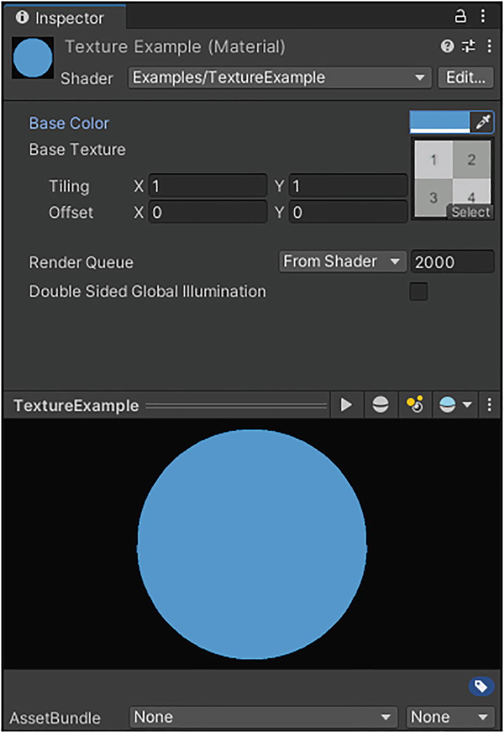
A screenshot of the texture example window depicts a color-shaded circle under the texture example shader.
A theoretical version of the TextureExample shader attached to a material
In this screenshot, you can see the Base Texture property is now visible. I have attached a checkerboard texture to the property – you can use the small “Select” button on the texture preview to open a window containing all textures in your project. We haven’t modified the fragment shader to make use of the texture yet, so the preview at the bottom is still a solid color.
- For any texture named {TextureName}, Unity creates a variable called {TextureName}_ST.
This variable contains the tiling and offset values inside a four-dimensional vector.
The (x,y) components store the tiling vector, and the (z,w) components store the offset vector.
“S” stands for “scale,” while “T” stands for “translation.”
- Unity also generates the variable {TextureName}_TexelSize.
Texel is a term that stands for “texture element,” the same way pixel stands for “picture element.”
The (x,y) components store 1.0/width and 1.0/height, respectively. That may seem strange, but these values are used often in calculations.
The (z,w) components store the unmodified width and height, respectively.
- Lastly, the variable {TextureName}_HDR is generated, but it is only helpful on High Dynamic Range–encoded textures.
An HDR texture (and HDR technology in general) represents each color channel of each texel with more than the standard 8 bits of data.
This lets us encode a greater range of values, and we can reproduce images with more accurate color and lighting details.
This variable can be used with the DecodeHDR function to properly extract HDR data from such a texture.
Declaring optional texture variables
Now that we can send textures to the shader via properties, it’s time to talk about how exactly we will map those textures onto the surface of the object.
Texture Coordinates
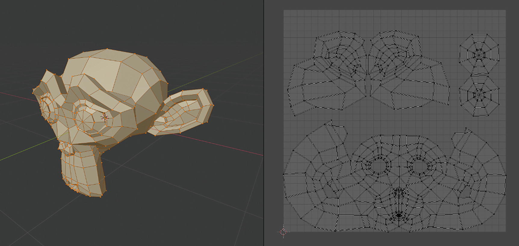
A screenshot depicts the 3-D model of an abnormally shaped head and facial features and the U V mapping of each segment.
On the left, a 3D model in Blender, a 3D modeling software package. On the right, its associated UV mapping
The mapping doesn’t need to be contiguous – two adjacent faces on the mesh could map to opposite parts of the texture. As you can imagine, UV coordinates are a bit like trying to wrap a square sheet of wrapping paper around any weirdly shaped 3D object imaginable, but we’re allowed to cheat and cut the paper into tiny bits and stick them around the object however we want. 3D artists wrap people’s birthday presents creatively!
For UV coordinates, the type is float2, and the shader semantic is TEXCOORD0 (which stands for “texture coordinate 0”).
Unity supports more than one set of UVs, so if you wanted to use different UV channels for different textures, then you could specify multiple additional channels using the semantics TEXCOORD1, TEXCOORD2, and so on up to TEXCOORD7.
Some platforms may support more UV channels, but you will always have these eight available. Each of these texture coordinate slots is called an interpolator.
Passing texture coordinates to the vertex shader
The “standard” set of UVs, which is most commonly used for texture mapping, is TEXCOORD0. You can author UV channels on a mesh however you want, but almost every shader will assume you are using TEXCOORD0 for mapping regular textures to your mesh, so we will stick with that for our shaders.
Passing texture coordinates from the vertex shader to the fragment shader
Passing UV data to the fragment shader without modification
No matter how you change the tiling and offset values in the Inspector, your texture won’t look any different if you use this shader. Thankfully, one of the macros included in Unity’s shader include files will apply the transformations for us. The macro is called TRANSFORM_TEX, and it automatically uses the {TextureName}_ST variable to apply the mapping. TRANSFORM_TEX takes the input UVs and the texture name as inputs. Thankfully, this macro uses the same name in the built-in and Universal pipelines.
If you don’t define {TextureName}_ST anywhere and try to use the TRANSFORM_TEX macro with the corresponding texture {TextureName}, then you will get an “undeclared identifier” compile error. Unity will helpfully let you know which variable is undeclared.
Passing UV data to the fragment shader using TRANSFORM_TEX in the built-in pipeline
Passing UV data to the fragment shader using TRANSFORM_TEX in URP
We will be able to access these UV coordinates in the fragment shader. During the rasterization process, which happens between the vertex and fragment stages, Unity will interpolate the per-vertex UVs we just calculated to give us per-fragment UVs, which we can use to apply the right bits of the texture to the mesh. The process by which we grab values from the texture is called texture sampling.
Texture Sampling
Sampling a texture using tex2D
Recall that vectors in shaders, like the float4 vector here, are just a collection of numbers – we can add or multiply them together. We had previously used the _BaseColor property to output only a solid color, so we can multiply that by the texture sample we just did to output a texture with a tint. It’s common in shaders to supply both a base texture and a base color because you may want to create a handful of materials with the same basic pattern (such as a checkerboard like I used in Figure 5-1), but with different coloration.
A fragment shader that outputs a tinted texture
This code is identical between the built-in pipeline and URP. If you look at the material’s Inspector window now (see Figure 5-1), then the preview will display the texture tinted with the base color you chose. If you tweak the tiling and offset settings, then the preview window will update to reflect your changes.
Texture Support in Shader Graph
We will follow roughly the same steps to create this shader in Shader Graph. To start off with, create a new Unlit graph and name it “TextureGraph”. We’ll start by adding the same Base Color property we used in HelloShaderGraph. Then we’ll need to add a new texture property.

A screenshot depicts the properties of base color and texture mentioned under the texture graph.
The Base Color and Base Texture properties for TextureGraph
In Unity versions from 2021.2 and up, you will see a Use Tiling and Offset option on all texture properties, which adds the Tiling and Offset vectors to the Inspector window. However, in versions below 2021.2, Unity won’t display the tiling and offset vectors for a texture on the material Inspector window, so you must create those properties yourself.
Applying Tiling and Offset Vectors

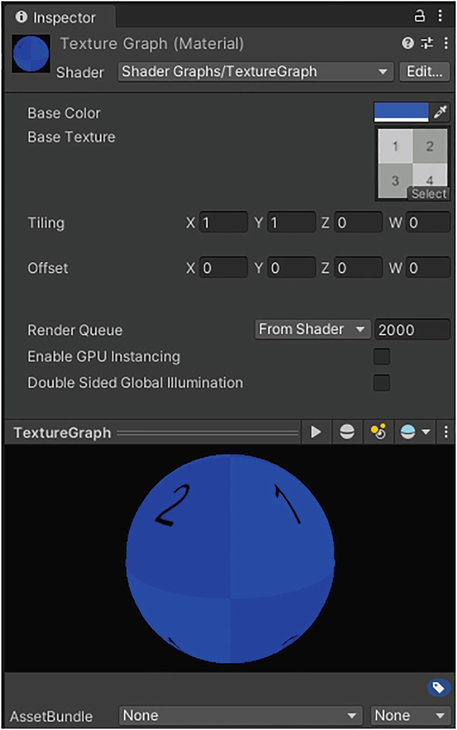
A screenshot of the texture graph window depicts a color-shaded circle under the texture graph shader.
A material that uses the TextureGraph shader. So far, we have not sampled the texture inside the shader, so it only uses a block color for its output
Let’s see how to apply these values in Shader Graph. We don’t need to do these steps if you’re in Unity 2021.2 and above, but it will still be useful to read this section anyway. Unlike with shader code, we don’t need to deal with passing the UV data between shader stages. Unity does all of that behind the scenes and provides a UV node to obtain texture coordinate data about the mesh. To make use of the Tiling and Offset properties, we can add a node called Tiling And Offset, which acts somewhat like the TRANSFORM_TEX macro we used in code; it takes a base set of UV coordinates and scales it by the Tiling input and then translates by the Offset input.

A screenshot of the shader graph for tiling and offset which has nodes for tiling and a U V shaded graph.
Using tiling and offset values to modify UVs in Shader Graph
The output of the Tiling And Offset node is a new set of UV coordinates with those transformations applied to the original UVs. If we wanted to, we could pass any Vector2 into the Tiling And Offset node and treat those as UVs, even if they didn’t originate from a UV node – in fact, that’s how many custom effects are made. We’ll see how to do that later.
We output the TilingAndOffset property directly to the Tiling slot.
Since the Tiling slot expects a Vector2, it will truncate the property to its first two components (x, y).
We output TilingAndOffset into a Swizzle node. The Red Out is set to Blue, and the Green Out is set to Alpha. Then we connect the Swizzle output to the Offset slot.
In all, the Swizzle node will output (z, w, x, x), but it is truncated to just (z, w).

A screenshot of a tiling and offset shader graph that has a swizzle node linking the tiling and offset node and the offset of the shader graph.
The Swizzle node lets you rearrange the components of a vector
Now that we have our UVs, we will use them to sample the texture.
Sampling Textures

A screenshot depicts the base texture and tiling and offsets nodes that have their nodes for U V, tiling, and offset.
Sampling a texture using tiling and offset in Shader Graph
If you’re using Unity 2021.2 or above and you ticked the Use Tiling and Offset option in the settings for Base Texture, then the Sample Texture 2D node automatically applies those tiling and offset options. That’s a lot more convenient as we avoid needing to add so many nodes to the graph! Although it’s not much of a problem because this graph is small, when we start making larger graphs, space-saving features like this are going to become invaluable.
The Type dropdown is used to determine whether the node will output colors (in Default mode) or normal vectors (in Normal mode).
The Space dropdown determines which sampling space is used. This option is only relevant for normal mapping, which we will revisit in a later chapter.

A screenshot depicts the vertex and the multiply node for the fragment and it has a base color and a sample texture 2 D node.
Outputting the combined color to the Base Color on the master stack
A screenshot of the texture graph window depicts a checkered sphere under the Texture Graph shader.
The material Inspector for a shader made with Shader Graph
At this point, the graph we just made should have parity with the shader code we wrote. However, there’s a lot more to textures in Unity than just simple sampling like this. Let’s look at some of the technical details of texturing and then customize how each texture is read while sampling.
Mipmaps and Level of Detail
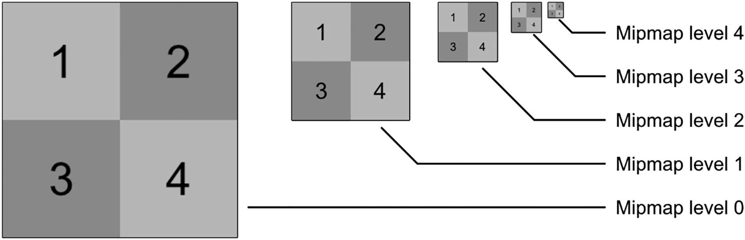
A diagram depicts five checkerboards for Mipmap levels 0 to 4 and the size of the boards gets smaller as the level rises.
A texture with different mipmap levels. Each time the mipmap level increases by one, the texture is scaled by a factor of half along both axes, resulting in a texture that is one quarter the size
A single large object with parts that are both close to and far away from the camera could be textured using more than one mipmap level. It is also possible to manually control which mipmap level is sampled inside a shader using alternative versions of the tex2D function and the Sample Texture 2D node in HLSL and Shader Graph, respectively.
Level of Detail
The term Level of Detail (LOD) usually applies to 3D meshes. In this context, when a mesh is far away from the camera, we can swap it for a version with fewer triangles, so we save precious rendering resources for close-up details we can actually perceive. It is also applicable to texturing. You can think of mipmaps as the 2D analogue of a 3D mesh LOD system because we use mipmaps to sample faraway objects with lower-resolution textures.
Texture LOD in HLSL
Using tex2Dlod to sample a specific mipmap level (in this case, the 3rd level)
The tex2Dlod function, unlike tex2D, can be used within the vertex shader. It might seem strange, given what we’ve learned so far, to be using textures within the vertex shader, but it can certainly be helpful. There are many effects with work on object geometry that can benefit from reading precalculated values from a texture and applying those values to each object, such as a vertex shader that simulates rolling waves on the surface of the sea by reading wave data from a texture – we will see effects like that later.
Texture LOD in Shader Graph
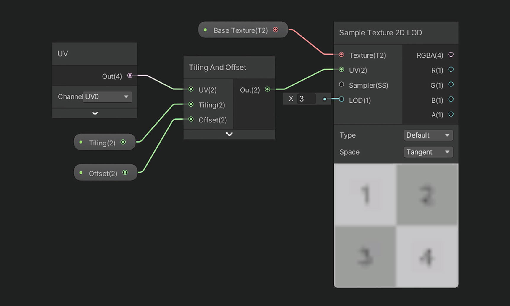
A screenshot depicts the sample texture 2-D L O D with base texture and tiling and offsets nodes that have their nodes for U V, tiling, and offset.
Using Sample Texture 2D LOD in place of Sample Texture 2D. The 3rd mipmap level has been specified in the LOD input, so the preview’s resolution is noticeably lower than the original texture
While using Shader Graph, you will find that some nodes will refuse to connect their outputs to either the vertex stage or fragment stage outputs on the master stack. This means that those nodes are incompatible with that stage. For example, Sample Texture 2D will not connect to any nodes in the vertex stage, but Sample Texture 2D LOD will connect to nodes in either stage.
Sampling Options

A screenshot of the 2-D texture import window depicts various settings and a checkerboard. The filter mode is bilinear, and the wrap mode is on repeat.
The texture import window of an example texture. The Wrap Mode and Filter Mode settings are seen roughly in the middle of the list of settings
Wrap Mode
The default behavior is to Repeat, which acts like the texture gets repeated infinitely, so sampling at (1.5, 3.5) is the same as sampling at (0.5, 0.5). Otherwise, we can pick the following modes.
The Clamp option locks your UVs to the 0–1 range. Sampling at (1.5, 3.5) is the same as sampling at (1.0, 1.0), and sampling at (−7.0, 0.3) is the same as sampling at (0.0, 0.3).
Mirror will sample normally between the 0 and 1 range, then mirror the UVs between 1 and 2, then sample normally again between 2 and 3, and so on. Sampling at (1.2, 1.3) is like sampling at (0.8, 0.7).
Mirror Once is like Mirror, but it will only mirror one time and then clamp. Sampling at (−0.1, 0.2) is like sampling at (0.1, 0.2), but sampling at (−2.3, −1.0) is like sampling at (−1.0, −1.0).
Finally, the Per Axis sampling mode lets you define one of the preceding four options for each of the two axes independently. You could Repeat along the u-axis and Clamp on the v-axis, for instance.

An illustration depicts the repeat, clamp, mirror, and mirror once warp modes which are applied to an example checkerboard texture.
Wrap modes applied to an example texture. The material used to render these textures uses the TextureExample shader with 4× tiling and an offset of –1.5 in both axes
Filter Mode
The Filter Mode, on the other hand, defines what type of blurring is used on the texture. One of the problems with texture mapping is that the pixel density of your screen (or, at least, the pixel density of the portion of your screen taken up by an object) doesn’t always line up with the texel density of the texture on that object. In a perfect world, pixels and texels would always line up 1:1 so that we can sample the texture, apply that color to the screen pixel, and sleep easy knowing that the mapping was absolutely perfect.
Point filtering is perhaps the easiest to understand. If a UV coordinate does not line up exactly with the center point of a texel on the texture, then the UV gets rounded to the nearest one, and the color of that texel is sampled. For that reason, point filtering is sometimes called nearest-neighbor filtering.
Bilinear filtering, which is the default option, will interpolate between the (up to) four closest texels to the specified UV coordinate. If the UVs match up to the center of a texel exactly, that texel’s color is sampled. Otherwise, this filter works by taking a weighted average of the color of the four closest texels to the UV coordinate.
Trilinear filtering works like bilinear filtering with an added step. If the UV coordinate is being used to sample on the overlap between two mipmap levels on an object, then the resulting color is interpolated between those mipmaps. In effect, this is the result of using bilinear filtering on both mipmap levels and then interpolating between both those values.
Each combination of Wrap Mode and Filter Mode looks different. By default, when sampling a texture inside a shader, the behavior specified in the texture import settings will be used, but it’s possible to override those settings using sampler states.
Sampler States
Sometimes it will be necessary to override a texture’s default filter and wrap settings for a specific shader effect. Both HLSL and Shader Graph have mechanisms for doing so.
Sampler States in HLSL
So far, we have seen the sampler2D type, which bundles together the texture data (the texels that make up the texture) and the sampler data (the combination of wrap and filter settings) into one object, and the tex2D function that reads from a sampler2D. However, sometimes we want to separate the texture data from the sampling settings. For instance, we might find that we’re using many textures on an object, but we only want to use one set of wrap and filter settings for all of them.
Add a texture to your Assets folder and tweak the Wrap and Filter modes as you like.
Include the texture inside Properties in ShaderLab using the syntax we have seen before.
In HLSL, define the texture in your Properties list using the Texture2D keyword instead of sampler2D. Texture2D can be placed outside the UnityPerMaterial buffer in URP, like sampler2D.
Add an extra variable of type SamplerState. The name of this variable is sampler_BaseTex; in general, the variable sampler_{TextureName} accesses the wrap and filter modes associated with the {TextureName} texture.
Instead of using tex2D, use the Sample function. This function is defined on the Texture2D object directly, so to sample _BaseTex, we now say _BaseTex.Sample(sampler_BaseTex, i.uv).
Sampling multiple textures using only one SamplerState object
Some older graphics APIs (such as OpenGL ES) only support the use of sampler2D. You cannot separate textures and samplers using those APIs.
SamplerState pointrepeat;
SamplerState Point_Repeat;
SamplerState sampler_RepeatPoint;
You can specify wrap modes per axis by naming the sampler “RepeatUClampV”, for example, which would repeat along the u-axis and clamp along the v-axis. The available names are the same as the filter and wrap options on the texture import window.
Sampler States in Shader Graph
SamplerState objects are also supported by Shader Graph. We can create a Sampler State node, which has drop-down options for Wrap and Filter. They are the same as before, except “Bilinear” is renamed “Linear” in the filter settings. We can link the output to the Sample Texture 2D node, which accepts a Sampler input.

A screenshot depicts the sample texture 2-D with a mirror checkerboard and having a base texture, sampler state, and tiling and offset nodes.
Using a sampler state to override texture settings in Shader Graph
Try out different combinations of Filter and Wrap settings to see what effects you can create. For example, point filtering works great for pixel art, but bilinear filtering may work better for high-resolution organic textures.
Summary
Basic textures contain color data about the surface of an object. We can sample them using tex2D or a Sample Texture 2D node.
Textures are mapped onto objects according to a set of coordinates called UVs.
Unity provides the TRANSFORM_TEX macro to assist with scaling and offsetting textures.
The Tiling And Offset node does the same thing in Shader Graph as TRANSFORM_TEX does in shader code.
Mipmaps are smaller versions of a texture that are automatically generated by Unity. We can access them using tex2Dlod or a Sample Texture 2D LOD node.
We can modify the Wrap Mode of the texture to influence what happens when we sample the texture outside of the typical 0–1 UV boundaries. We could clamp to a boundary texel, repeat the texture, or mirror across the texture boundary.
The Filter Mode controls what happens when we use UV coordinates that don’t quite match up exactly to the centroid of a particular texel. We can snap to the nearest neighbor with point sampling or blend between adjacent texels with bilinear or trilinear filtering.
Sampler states can be used to modify the wrap and filter settings of a texture within an individual shader.