
Solutions in this chapter:
So far in this book, we have discussed in depth many mobility configurations, all of them based upon one of the most important inventions of mankind: the wheel. In this chapter, we will try to emulate what nature invented long before the wheel to provide mankind with a mode of transportation—legs!
Legged robots are rather impractical for all but a few special applications. However, there is much to learn in designing and building a walking robot, which is both challenging and fascinating.
This chapter owes a lot to the great designers who published their creations on the Internet, and patiently explained their choices through text and pictures, including Kevin Clague, Yoshihito Isogawa, Joe Nagata, Miguel Agullo, and many others.
How can one define walking? It’s the process of lifting a leg from the ground while the other legs (one or more) support the body. When the leg has been lifted, it is advanced and lowered back to the ground. From there, the process continues with another leg, and so on.
The crucial point is this: What prevents a creature from falling down when it lifts its leg? To discover this, we need to introduce some basic concepts from a branch of physics called statics, which explains the laws of balance.
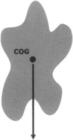
The weight of an object is the resulting effect of the force of gravity against the mass of the object. To describe a force, you need to determine three variables: its magnitude, direction, and point of application. For example, if you want to move a piece of furniture in your room, the magnitude is the amount of force you must apply to make it move, the direction is the bearing of the course on which you’re pushing it, and the point of application is where you place your hands to apply the force. Returning to gravity, its magnitude is proportional to the mass of the object and its direction points vertically downward, but where is its application point? To answer this question, you should consider an object as being the sum of a very large number of very small particles, each one having its own mass. The gravity exerts a force upon every particle, and thus all of them can be considered a point of application. However, physics teaches that a combination of forces can be interpreted as a single force—called the resultant—that has its own magnitude, direction, and point of application. The resultant force of gravity has a magnitude that corresponds to the weight of the objects, a direction pointing downward, and a point of application called the center of gravity (COG) of the object (see Figure 15.1).
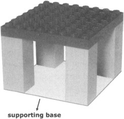
The force of gravity acts on an object and tries to move its COG as close to the ground as possible; this is why objects fall and shift until they reach a stable position. But what makes a position stable? Statics teaches that a body becomes stable when the vertical passing for its center of gravity falls inside its supporting base. The supporting base is the surface whose perimeter results from connecting the supporting points with straight lines. A supporting point is any point on the object that is in contact with the ground or with any other stable object (such as the floor of your room, or your desk). For example, a book placed on a table has the whole surface of its cover in touch with the table, and that defines its supporting base. A table has four legs, each one having a small surface in touch with the floor: Its supporting base is the area delimited by the legs, which includes points untouched by the table (see Figure 15.2).
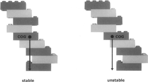
Every child learns this rule by experience when building towers of stacked blocks: While the COG remains within the supporting base, the tower is stable; as soon as it falls outside the base, the tower itself falls down (see Figure 15.3).
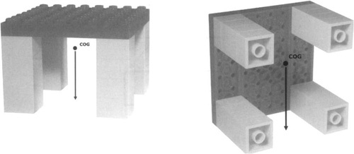
Okay, now that we know the rule, how do we find the COG of an object? For objects that are symmetrical in shape and density, the COG coincides with their geometrical center, but in more complex objects the COG is not very easy to find, and it is not guaranteed to be inside the object. A table is again a good example: The COG of a typical table lies somewhere below its top, as demonstrated by the fact that it has more than just one stable position (see Figure 15.4).
Fortunately, we do not need to find the actual position of the COG of our robot. We are actually interested in the position of the vertical line that passes through the COG, in order to see whether it falls inside the supporting base. This is easier to find: If our robot is mainly symmetrical, this line will pass very close to its geometrical center. Thus, what we actually need to do is to look at the robot from the top and determine whether the COG falls over the supporting base delimited by the legs.
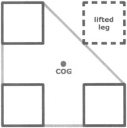
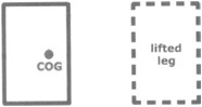
For example, in Figure 15.5, we see a scheme that represents a robot with four large legs (top view). One of the legs is lifted, and we see that the COG still falls inside the surface delimited by the other three legs. And thus, the robot remains stable.
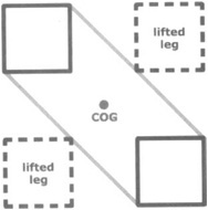
The same robot can stay balanced even with just two legs, because the COG still falls inside its supporting base (see Figure 15.6).
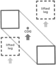
When the robot advances the two lifted legs, part of its mass moves forward, and the COG moves forward as well. And because the large contact surfaces of the legs delimit a zone wide enough to make the moving COG fall within the boundaries (see Figure 15.7), the robot, again, remains stable.
When we are using robots with more than four legs, we do not need to rely on their size anymore. A six-legged robot, for example, can walk with very thin feet provided it always has at least three of them touching the ground (see Figure 15.8).

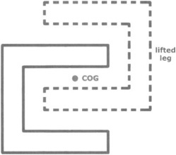
On the contrary, when we start reducing the number of legs, things become more complicated. The making of two-legged (biped) robots requires a very careful design. A little trick is to build U-shaped legs that partly interlace, providing a large support for the robot (see Figure 15.9). LEGO suggested a similar approach in one of its Idea Books (8891, back in 1991).
Though this works, it’s a bit like cheating! If we want to emulate the way we human beings walk, we must understand what happens in the human body. Let’s do a simple experiment. Stand still, being sure to distribute your weight evenly over your feet. Keep your arms at your side and keep all your muscles relaxed. Now slowly try to lift one leg: Your body tends to fall to that side. While walking under normal conditions, you unwittingly move your COG over one foot before lifting the other. This gives you balance and stability and prevents you from falling.
This is the behavior that we have to replicate to build a true biped robot. We have to shift its COG over one foot before lifting and advancing the other (see Figures 15.10 and 15.11).

Actually, the way human beings and animals walk follows not only the rules of statics but also those of dynamics, the branch of physics that deals with matter in motion. When a man runs, for example, he is in dynamic balance, producing forces that oppose gravity and temporarily violate the rules of statics. To understand how this happens, you can study how you walk, and also look carefully at how animals phase their walking (bipeds, four-legged animals, insects, and arachnids). For example, elephants and other very large animals lift only one leg when walking slowly, to keep the static COG within the triangle bounded by their remaining legs. Once the pace picks up, the opposing gait takes over, which is similar to the sequence we described in Figures 15.6 and 15.7. Most four-legged animals use this scheme when trotting. At further increases of speed, such as in galloping, dynamic stability is more important than static: Only one leg needs to keep contact with the ground, and this allows the animal to cover more ground with every cycle.
Building a robot that walks or runs using dynamic balance is a very complicated task, and for this reason, in this chapter we will stay inside the comforting walls of statics.
Whatever kind of walking robot we’re going to build, we must find a way to convert the rotary motion provided by the electric motors into the proper sequence of movements necessary for a leg to work. Animals and human beings use a very complex geometry operated by an impressive number of independent muscles. We must stick to the constraints imposed by the MINDSTORMS system, thus finding simpler solutions.
Figure 15.12 illustrates an initial idea: a leg mounted on two gear wheels of the same size, which are then connected in phase through a third gear. It’s very important that the leg attaches to two corresponding holes of the gears; otherwise, it won’t work because the holes will change their spacing as the gears turn.
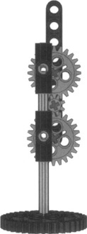
By driving any of the three gears, this simple leg will go up and down, forward and back, always in a circle. The leg always remains vertical. Figure 15.13 shows a slightly different approach, where only one point of the leg is attached to a wheel, and the leg itself slides freely into a rotating support (fulcrum).
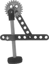
In this assembly, the terminal point of the leg describes an ellipse—a flattened circle—whose height is equal to the distance between the uppermost and lowermost positions of the point where the leg is attached to the wheel, and whose length is a function of the distance between the fulcrum and the wheel. The closer the fulcrum is to the wheel, the longer the ellipse and, consequently, the stride of the leg will be. You can adjust this distance to make your robot take longer or shorter steps, affecting its speed. We invite you to experiment with this setup, changing the distance between the wheel and the fulcrum, to understand the effect on the stride. Later in the chapter, we’ll use this feature to provide a legged robot with turning capability.
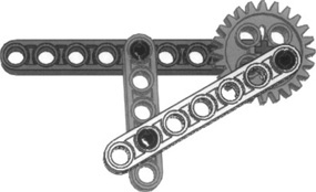
More complex leg geometries are also possible (see Figure 15.14). Designing legs is almost an art—it requires good intuition, and a lot of patience to test and improve your initial idea.
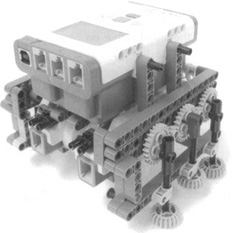
Let’s start by building a robot with four legs in order to demonstrate the center of gravity principle explained in Figures 15.5-15.7. The architecture is very simple, and symmetrical:
Keep the COG as close as possible to the center (see Figure 15.15). We built it solely from NXT parts.
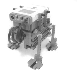
Removing the NXT, you’ll notice there’s a single motor, which through a series of gears provides motion to the front and rear leg assemblies (see Figures 15.16 and 15.17). However, notice the phase of the legs: They are diagonally paired. The front left goes together with the rear right, and the front right accompanies the rear left, which implements the walking scheme shown in Figures 15.6 and 15.7.
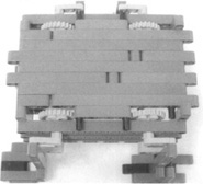
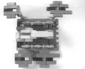
The legs follow the scheme of Figure 15.12, where just the gear wheels are inside the robot, their axles mounted on short 1 × 3 liftarms to which the legs are connected (see Figure 15.18).
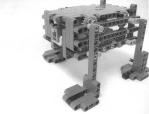
When the robot walks, it lifts two legs diagonally opposed, while standing on the other two (see Figure 15.19). Even when moving the legs, this robot always remains symmetrical; thus, its COG doesn’t change position.
There’s actually not much this robot can do. It’s easy to build, and somewhat instructive, but it’s able to go only forward in a straight line, and backward. You can mount two front and rear bumpers to make it reverse direction, but that’s all you can expect from it. To provide your robot with directional control, unlocking all the opportunities that navigation affords, you need further sophistication. Let’s move on and discuss some more challenging projects.
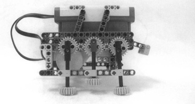
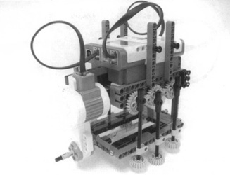
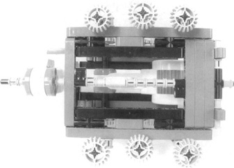
By increasing the number of legs, you can easily make a steering walker. The robot shown in Figure 15.20 has six legs similar to that in Figure 15.12.
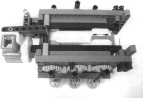
The left and right leg groups are powered by two independent motors (see Figure 15.21), and in each group the wheels are phased so as to have the middle one raised when the front and rear legs are lowered (see Figure 15.22).
This robot turns and walks. You can make it turn by stopping or reversing one of the motors as though it were a skid steer drive. But it’s affected by a serious problem: stability. The two groups of legs are not synchronized. Because of this, only the central legs are down at certain times. Because two legs are not enough for a stable balance, the robot tilts forward or backward a bit, ensuring that the additional legs make contact. As a result, its walking is rather irregular and jolting.
What could you do to smooth the walking motion? Using two sensors to detect the position of the legs, you could keep the two groups in sync so that one side goes on the middle leg only when the other one has two legs down.
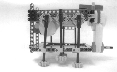
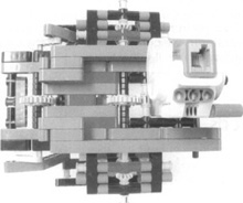
There is another approach, more on the hardware side, that requires you to vary the geometry of the legs to make them change their stride. The left and right leg groups are connected together and they are powered by a single motor so that the robot is always supported by a triangle such as that shown in Figure 15.8. To change the stride of the legs, you have to change the distance of their fulcrums from the gear wheels. The robot in Figure 15.23 uses this technique.
All the legs are powered by a single motor, while the second motor controls the leg geometry (see Figure 15.24).
It’s crucial that you connect the six legs in phase so that each side has the middle leg raised when the other two are down, and the left side has the middle leg down while the right one has its middle leg up (see Figure 15.25).
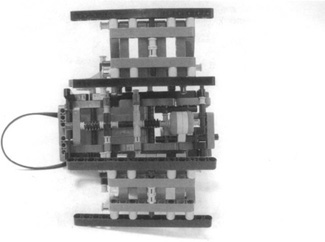
The fulcrums of the legs are attached to a swinging chassis that the second motor can incline on one side or the other (see Figure 15.26). The stride of the legs becomes shorter at the side where the fulcrums have been lowered, and longer at the other, thus making the robot turn.
The front and rear sides of the swinging chassis are operated through a long joined axle that is connected by a motor at the back of the robot (see Figure 15.27).
This robot needs no sensors to control its motion. When you want to make it turn, switch the motor on to the desired direction for a second to change the geometry, and then brake it to hold it in position. Recall that floating the motor might allow the swing chassis to turn. To resume straight motion, let the motor float and the swinging chassis will return to its central positions after a few steps.
The limit of this architecture is that the robot will turn only with a very large radius. It will be able to follow a line only if this doesn’t make tight angles—a right angle, for example.
To give high maneuverability to your robot, you must remain with a skid-steer type drive, possibly increasing the number of legs to improve stability.
Biped robots are among the most challenging projects we face. In a biped, the position of any single part, any single gram of mass, is critical to a stable balance. If you replicate the designs that follow, you will see that all of them walk quite smoothly, but you will also discover that you can’t add additional parts anywhere in their body and not feel the pain!
We will go through the approaches described in the section “The Theory behind Walking,” earlier in this chapter: interlacing legs (Figure 15.9) and COG shifting (Figure 15.11). For the latter category, we will explore a technique that requires that the whole body of the robot bend at the ankles to move the COG over a foot. In addition, there is also a technique (not described here) where an independent mechanism moves a mass from one side of the robot to the other to change the position of its COG.
At the end of the section, we will give you some tips about the next step in the challenge: the making of a biped robot capable of turning!
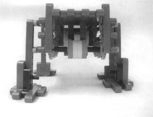
Let’s start with a biped based on the technique shown in Figure 15.9 using interlacing legs. The feet must be U-shaped and large enough to support the weight of the whole robot (see Figure 15.28, NXT MINDSTORMS parts only).
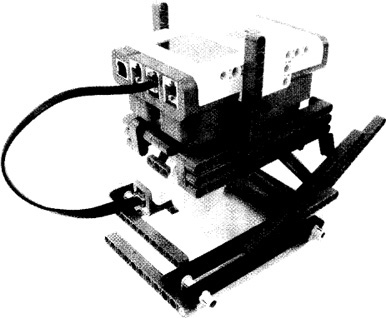
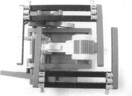
This robot uses a simple gearing, only an 8t and a 40t gear. The axle of the 40t connects to two opposing liftarms that operate the legs. The motor shaft has been prolonged with an axle (see Figure 15.29).
The leg geometry is very similar to the one in Figure 15.14, but here we used a double series of parallel beams in order to form two connected parallelograms, an upper (body to knee) and a lower (knee to foot) one (see Figure 15.30). Making this allows the foot to always remain parallel to the body, and thus the body always parallel to the ground.
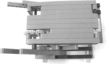
When you look at the robot from the bottom, it’s easy to see how the feet interlace with each other (see Figure 15.31).
In our current design, the feet rest flat on the ground (see Figure 15.32). On other designs similar to ours, the feet are not flat. Nagata’s Walker ND1 (see Appendix A), for example, has protrusions at the end of each inner tip of the feet (two on each feet). These tips compensate for the slackness of the leg that otherwise would make the robot lean at the side of the lifted leg, causing the COG to move beyond the base and make the robot fall. A similar feature is also observed on the interlacing-leg bipedal robot described in our RCX publication, although it only uses a thin plate instead.
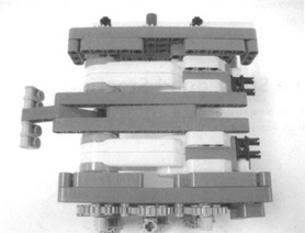
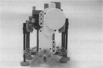
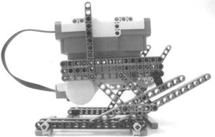
We will describe an approach to COG shifting of a walker by way of bending its ankle sideways in order to carry the COG over to the resting foot. The robot in Figure 15.33 uses this technique: You’ll notice that the right leg inclines outside and that the NXT rests over the foot.
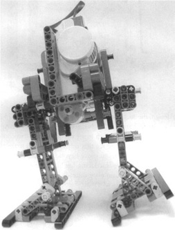
We used the leg designed by Miguel Agullo for his very nice Hammerhead (see Appendix A). The key component of the ankle is a crankshaft that manages the bending of the leg over the foot (see Figure 15.34). It looks pretty funny as it walks, lurching from side to side.
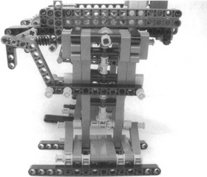
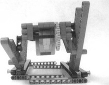
The hips are free to swing back and forth, and their supporting axle serves to also transfer motion to the ankle with a technique similar to what we described for the making of synchro drives or front wheel drive cars (see Figure 15.35). A second axle at the rear provides motion to the legs, through two crankshafts and two liftarms.
This walker uses a single motor and two worm gear and 24t pairs (see Figure 15.36).
The difficulty of this model lies in finding the proper synchronization between ankle and leg movements. If you decide to give this technique a try, we suggest you follow Miguel’s detailed instructions on his site (see Appendix A) to replicate his geometry.
Is it possible to make a biped robot turn? It is, though it’s definitely not an easy task. Once again, we invite you to experiment for yourself to find a working strategy. Observe your feet while you walk slowly, taking short steps and going straight: One foot is ahead of the other,
but they remain parallel, as if they were running on tracks. Now try to change direction, but only take the very first step. If you look at your feet again, you notice that they are no longer parallel: The foot that’s ahead is pointing in the new direction.
How can you emulate this behavior in your robot? We can do this by modifying the long legs utilized by either one of the bipedal architectures described here. The ankle-bending robot (Figure 15.34), for example, uses a 1 x 15 beam as its primary building piece for its leg construction. If, instead, it is replaced with two 1 x 7 beams connected with a joint that can vary the angle between the two beams, the legs can slightly converge or diverge. You will need a second motor to control the parallelism between the legs, and probably a third sensor to detect the straight position.
In this long chapter, we covered, hopefully, all of the most important aspects about the making of robotic walkers. Along the way, we discussed some important concepts, such as the center of gravity, that will prove useful in many other applications.
If you had the impression that we talked a lot about mechanics and not much about software, you’re right. The task of balancing the weight over the legs is by itself so demanding that not much space remains to make your robot perform other actions. Although we showed some possible basic behaviors such as line following, more complex tasks such as grabbing objects are usually beyond the scope of walking robots due to the changes brought about regarding their delicate balance. Precise navigation is also not very suited to walkers, because the natural tendency of their legs to skid a bit on the floor makes them somewhat unreliable for positioning.
However, all this shouldn’t keep you from experimenting with walkers. The pure reward of seeing them move compensates for all the effort put into building them. And who knows, in your enthusiasm you could develop some new solutions, or maybe design something as complex as a running robot!