
Solutions in this chapter:
Trying to emulate animals in form and function with LEGO’s MINDSTORMS NXT is a fun and instructive experience. You can approach the problem from different viewpoints—for example, concentrating your attention on the behavior of the animal, or on its shape; you can even create a pure fantasy animal or develop your own interpretation of some mythological creature.
In the following pages, we will discuss two robot projects: a monkey and a mouse. The robot monkey will try to emulate the swinging capability of real primates. Its function is to go hand over hand across a pole, dowel, or broom handle. The robot mouse is intended to be a roaming platform capable of performing multiple tasks. Like real mice, this robot has a playful nature as well.
Once again, the robots in this chapter will offer us the opportunity to revise and apply some of the concepts stated in the first part of the book. You will use a split gearbox to power the monkey’s shoulders. The mouse, meanwhile, will use a large ball through which we will implement a sort of automatic steering feature.
The last section of the chapter contains a list of proposals intended as starting points for new projects inspired by the world of animals: squirrel, mole, ostrich, kangaroo, crab—take your pick!
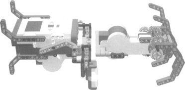
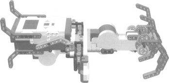
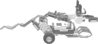
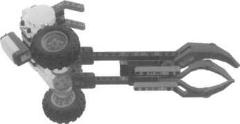
Our MINDSTORMS NXT monkey will need something to climb across. We recommend that you place a broom or similar object across two chairs. This will be the tree branch across which the monkey will be able to move back and forth. For the monkey to “see” his target point, you will have to drape a towel off the edge of the right chair, thereby providing the ultrasonic sensors a target that they can “see.” Your monkey will start on the left end of the broom handle and cross to the right. When he gets to the right side he will see the chair, turn, and then, because he has been counting the number of swings required to get to that point, he will go back across the broom handle to the point where he began. Figure 16.1 shows a model of a fully assembled monkey. Now let’s go through the step-by-step process of creating your monkey.
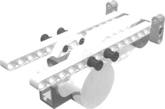
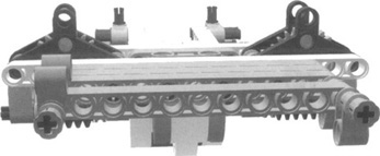
The center motor (see Figure 16.2) will drive the two rotating arms of your monkey. You’ll need the following parts for this step:
1x Motor
2x Pin with friction
2x Axle joiner perpendicular with two holes
4x Pin long with stop bush
2x Beam 1.15
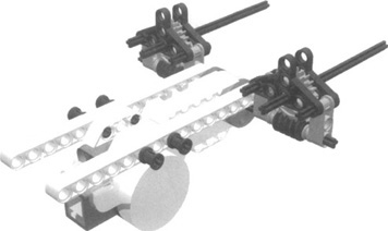
When assembling the shoulder, you can use twin axles to power two functions. To transfer power through two 90-degree angles and to add torque we will use the worm gears and a pair of 24-tooth gears. This reduces load on the motor and gives the monkey the needed muscle to swing from its arms. You’ll need the following parts for this step:
4x 1/2 Bushings
2x Worm screw gears
2x Gear 24 tooth
2x Axle joiner perpendicular with two holes
2x Axle 12
4x Triangles
4x Axle three with stud
2x Axle 8
Figure 16.3 is an example of what your monkey’s shoulder will look like.
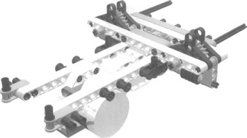
For this step, you’ll need the following parts:
1x Beam 1 x 11
1x Joiner perpendicular 1 x 3 x 3 with four pins
2x Beam 1 x 15
4x Axle pin with friction
1x Beam 1 x 5
8x Pin long with friction
2x Axle joiner perpendicular with two holes
2x Joiner perpendicular 3L
2x Bush
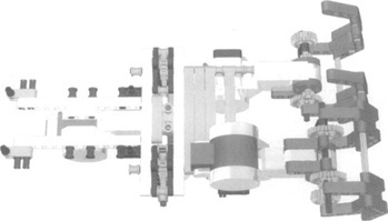
Figure 16.4 shows the shoulder/NXT brick bracing.
For this step, you’ll need the following parts:
3x Beam 1 x 11
2x Bush
9x Pin long with friction
4x Axle joiner perpendicular
Figure 16.5 shows the shoulder-to-arms support.
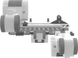
The arm motors (see Figure 16.6) will power your monkey’s hands. You’ll need the following parts for this step:
2x NXT motor
4x Pin long with friction
Monkey fingers are powered by your NXT motors. They use gear reduction for torque. With 3:1 reduction, you can give your monkey a grip so that he can hold on to the broom handle. You’ll need the following parts to assemble your monkey’s digits (see Figure 16.7):
2x Axle 10
2x Gear 20-tooth double-bevel
4x Beam 1 x 3
8x Pin long with friction
4x Axle 7
4x Gear 24-tooth
16x Liftarm 1 x 7 bent
14x Axle 3
4x Gear 8-tooth
4x Liftarm 2 x 4 L-shape
You’ll need the following parts for this step (see Figure 16.8):
1x NXT brick
2-Liftarm bent 2 x 7
2x Axle pin with friction
2x Axle joiner perpendicular double split
1x Utrasonic sensor
4x Liftarm double bent
2x Axle pin with friction
2x Axle joiner perpendicular double
1x Liftarm 3 x 5 L-shape
12x Pin with friction
2x Pin long with stop bush
Set up your monkey’s wiring by facing the NXT brick toward you. The wire for the left arm is labeled “A”, the one for the center shoulder motor is labeled “B”, and the one for the right arm is labeled “C”. Connect the ultrasonic sensor on port 4. Use the 20-tooth gears as tuning knobs to adjust the fingers when attaching them to the broom handle. Have both of your monkey’s hands grip the handle to start. Tune the shoulders at the worm gear axle so that when you are facing the NXT brick, the right arm motor is on the side of the NXT brick that is facing you. Adjust this until the motor’s 1 x 3 beam touches the bracing. Do not overtighten it. Adjust both hands so that they are closed over the handle. When the hands are in a gripped or closed possition, they should be at about 90 to 100 degrees from the vertical arm motors. If you have your monkey high up on something, protect him from acidental falls by using a tether line.
To program your monkey you will use a few of the more advanced features of the NXT-G: namely, Logic and Compare blocks, using data wires to send information. This will give your monkey the intellect to count how many swings he made, so he can go back to the start.
Figures 16.8 and 16.9 show the NXT-G code required for this application. Because NXT-G code is written in a horizontal fashion, it makes it difficult to display in publications such as this, so we have broken it into two chunks for ease of reading.
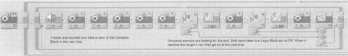
Most NXT programs are built within a loop, which keeps the program running. You can stop the program in a variety of ways. In this program, you will need to press the NXT Stop button (the gray square below the orange one). You can add a sound sensor and write some code to trigger the monkey to stop when you clap your hands.
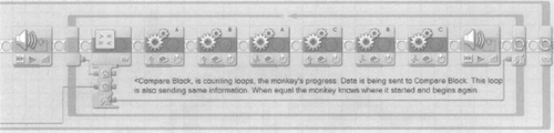
Figure 16.9 shows our monkey program. We started by adding a loop block set to execute forever. We placed two more loop blocks inside the main loop, then set both loops using logic and a counter. In the second loop, we placed a compare block (see Figure 16.10), and set it to equals. What will this do? The compare block will count the loops of the first loop block. The compare block remembers the count. When the ultrasonic sensor tells the first loop to exit, the second loop block knows how far it has to go back to reach the point where the monkey started in the second loop block.
Now let’s look at the ultrasonic sensor blocks and the logic block. For this application, you will use two ultrasonic sensor blocks. This technique could be used by different sensors or mixed sensors as well. You need to use two because the monkey makes a swinging motion in a right-to-left and left-to-right pattern for every loop. You don’t want the monkey to miss an object and run into a tree! Connect both ultrasonic sensor blocks to the logic blocks’ A and B hubs. Connect the result hub of the logic block to the end of the first loop. Set the logic block to Or. Now, if one or both of the ultrasonic sensor blocks detect an object in front of them, this information will tell the first loop to exit.
You will notice that there is one motor move block at the beginning of the program. This is telling all motors to brake on the A,B,C ports. This is so that when you place your monkey on the broom handle, it will hold on while things get going.
When you write a program it is a very good idea to test it before use. This robot has built-in stands (or legs) that facilitate the testing process. Test the functionality of all the motors at 50 percent power. A good test should work like this: Starting with both monkey paws closed, the right hand will open, the shoulders will rotate, the right hand will close, the left hand will open, the shoulders will rotate, and the left hand will close. This will repeat until you place your hand in front of the ultrasonic sensor, which will cause the monkey to perform the same motion, but in reverse. Test it and count the number of loops; notice whether the monkey goes back the same number of loops as it moved forward. If this works, the monkey is ready for action! Now set the motors to 100 percent and the monkey should be ready to swing.
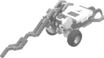
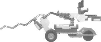
The mouse is a fast and timid creature. It is always on the lookout for danger. Our mouse has no legs, but it uses wheels and a ball castor for speedy turns and quick getaways. It has ultrasonic eyes that can see in the dark, and a microphone nose that hears the screams of startled people. His tail is a touch sensor; when you touch the tail, the mouse will scurry around (see Figure 16.11).
For this step you’ll need the following parts:
2x NXT motor
2x NXT rim
1x Beam 7
2x Beam 9
2x Beam 15
5x Axle 3
2x Axle 6
2x Pin long with stop bush
1x Touch sensor
14x Pin long
2x Axle pin with friction
2x Axle joiner perpendicular 3L
2x Beam 15
3x Pin with friction
4x Bush
2x Liftarm double-bent
2x NXT tire
2x Pincer Suukorak
5x Axle joiner perpendicular 1 x 3 x 3 with four pins
6x Liftarm bent 7
2x Axle joiner perpendicular
2x Axle 10
2x Axle 5
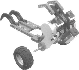
Figure 16.12 shows the assembled frame and motor.
For this step you’ll need the following parts:
2x Long pin
4x Axle pine with friction
2x Pincer Suukorak
6x Pin with friction
2x Beam 7
Figure 16.13 shows the assembled castor bottom.
If the tail is too heavy for your touch sensor, shorten it by removing a few of the liftarms used in this assembly. You’ll need the following parts for this step:
Figure 16.14 shows the assembled tail.
We must add a special note here: The 3 x 5 liftarm should be connected to the NXT brick through the #3 and #15 beams. You will have to lift the #15 beam up one hole to set it with the long pin. This gives the frame a slight preload. For this step you’ll need the following parts:
Figure 16.15 shows what the assembled mouse head frame looks like.
The mouse head is designed to move up and down; this feature mimics a mouse’s inquisitive nature and adds to its form. You’ll need the following parts for this step:
1x NXT motor
1x Axle joiner perpendicular
double split
1x Pin joiner dual perpendicular
8x Angle connector #6
2x Gear 24-tooth
4x Gear 8-tooth
6x Axle pin with friction
1x Ultrasonic sensor
3x Beam 3
4x Liftarm 3 x 5
2x Axle 12
5x Pin long with friction
1x Sound sensor
1x Axle joiner perpendicular
double
2x Angle connector #1
9x Axle 2
2x Gear 24-tooth
8x Pin with friction
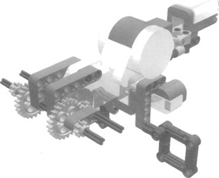
Figure 16.16 shows what the motorized mouse head looks like.
When wring the mouse, port A is for the mouse head assembly motor; ports B and C are for the motors to wheel motors; port 4 is for the ultrasonic sensor; port 1 is for the touch sensor; and port 2 is for the sound sensor. Place one of the two large balls provided with the NXT set into the mouse’s front paws for steering capability. You’ll need the following parts for this step:
2x Beam 5
2x Bush
1x Large ball
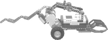
Figure 16.17 shows what you’ll see when you have mounted the mouse’s head to its body.
Because much of the form of our mouse is in its action, the program will have some actions that give the mouse robot more of its character. This example has some of the logic and compare blocks we discussed earlier. Compare blocks are very useful in terms of turning. Logic is needed to make a decision, or in this case, to use two sensors to activate the same operation or multiple functions.
This program is inside a loop block like the one we discussed earlier in the chapter. Here again, you start by placing a loop block that is first set to Forever (infinity). All your code blocks will be placed within this loop.
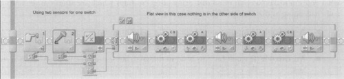
Take a look at Figure 16.18. This code segment represents the “character” part of the mouse, but we will use it in other parts of the program as well. You see here that a touch sensor and a sound sensor are wired to a logic block. Set the logic block to OR. Wire the logic block to the switch block and set it to value/logic. (This could have been done just by making the switch block a touch or sound switch block. But then it could not do both. This is one reason why a logic block is so useful.) The switch block (Figure 16.18) is set to flat view because the bottom line is empty and is coded only in the top section. This makes the code easier to read and follow. As a result of this code, if the touch or sound sensor is activated, it will use the top code of the switch block. If not, nothing will happen because the bottom section of the block has no code.
In the next segment (Figure 16.19), start by placing a switch block in the ultrasonic sensor mode to the right of the last segment; use 12 inches for the setting here. The top code of this switch block is the drive-forward code within your character code. The character code makes the mouse’s head move up and down and turn left and right. You can add sounds to give the mouse an “on the run” feeling.
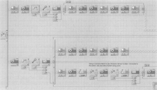
The bottom section of this switch block is the turning segment with the character code as well. Start by placing a motor move block (B/C=Stop). This will brake the mouse before it runs into a wall. Now place another switch block set to Value/Logic/True. Place the touch and sound sensors wired to the logic block and to the switch. The upper part of this switch has the same character code as before.
The bottom of this switch is the part of the program that directs the mouse to turn left and right. As the mouse approaches a wall, it stops, and then looks left and right. The ultrasonic sensor is measuring the distances and sending this data to the compare block. The larger value represents the direction of travel, as handled by the next switch block. Only the top section has code. If the value of one direction is greater than the value in the switch block, the mouse is already facing that direction. If the value of the other direction is greater than in the switch block, the mouse turns and the program starts again.
If you have a dog or cat, it probably will enjoy playing with the mouse robot. Be careful with dogs, as they tend to like mouse robots a little too much and may bite them. Also, note that you can program this robot to perform other tasks. For instance, you can make it follow lines, sounds, or light.
Nature is a wonderful source of inspiration, and you can collect tons of great ideas just by browsing through books about animals. You can use insects and spiders as templates for multilegged walkers; other creatures higher on the evolutionary scale present an incredible range of shapes and behaviors. Take your pick.
Matching shape to function is almost an art. Even our simple monkey required many trials before we felt satisfied with its design. The following list provides some examples of what you can make. Keep in mind that many other creatures which are at least as interesting and challenging as these are just waiting for you:
A squirrel. This robot would collect 2 x 2 bricks as though they were nuts, and perhaps bring them back to its hole (difficult).
An ostrich. It won’t bury its head in the sand, but it can hide its head between its legs.
A kangaroo. We like the challenge of designing a jumping robot, but so far we haven’t succeeded. The idea was to implement a sort of spring or rubber band mechanism that, when slowly loaded by a motor, could release its energy all at once, thus making the kangaroo jump. We conducted a few experiments, and although our prototype actually skipped and advanced a bit, we didn’t consider it fully successful. It’s still an open challenge!
An armadillo. This would roll up like a ball when disturbed.
An oyster. Even a simple animal such as this offers some ideas. For example, you can build one that closes its shell very quickly when someone steals its pearl, and the game could be to try to remove the pearl without being touched by the shell.
A dinosaur. This category includes such a broad variety of creatures that you shouldn’t have a problem finding one to emulate.
A porcupine or hedgehog. This one could raise its quills (axles) when detecting a stimulus.
A crab or lobster. This type of robot would clamp down on everything that touches its claws.
A koala. This would climb a tree (you’d probably need a specially shaped LEGO tree for this one!).
A mole. This would be a dark-seeking robot that looks for the darkest places in your room, presumably under a piece of furniture, and rests there until light disturbs it.
With additional MINDSTORMS NXT sets you could model two or more animals of the same type so that they can cooperate with each other as they perform certain tasks; for example, ants. Or you could model animals of different types so that one hunts the other, which tries to escape. In addition, you could build a multi-NXT animal robot that could have many more functions.
In this chapter, we discussed how to design a robot based on existing creatures. In addition to technical issues, you have to face the difficulties that come from the need to match shape to function. In fact, in previous chapters, we concentrated on solving technical problems without introducing concerns about the size or appearance of our robots. However, you cannot emulate animals without carefully studying the shape of the robot; actually, that is the most important factor, and it’s what makes your robot look like an animal instead of a vehicle. Decisions about the appearance of a robotic animal usually come before any other mechanical choice, and they will push you to look for technical solutions that suit your desired structure. Sometimes you will find them and will be able to carry out your original design; other times you will have to introduce some adaptations into the structure to make a mechanical solution possible.
The monkey and mouse described in this chapter are good examples of this approach. One of our goals in building the monkey was to build it with the strength it needed to hang on to a branch (represented by a broom handle). This led us to use various gear systems to drive its shoulders and hands.
The mouse project started with a different premise: The robot had to be mobile and fast. When making shapes from beams, we are confined to angles that may not emulate the real shape of a mouse. But it can have a degree of similar appearance. Much of the character of the mouse, then, is evident more in its programming.
Having stated the importance of shape when emulating animals, we don’t want you to think that shape is the only thing that counts. You should take into account what you learned in previous chapters, paying particular attention to the strength of the structure, the gear ratio of the mechanisms, and the effectiveness of the sensors.
As for programming, start with a simple program and test it for function. It is best if your first programs have power settings that are as low as possible. This way, you can be sure the program will function the way you intend. If you have a problem that causes binding, or a mechanical issue that results in limited travel, you can stop the program and change certain parameters. Once you have a simple program that functions correctly, you can add more complexity one step at a time, which will make the program much easier to debug later.
The last lesson to remember from this chapter is that by studying and observing animals, you can learn many tricks that are useful to robotics. Remember: Form and function are a balancing act of engineering. Animals provide endless inspiration when it comes to challenging robotic projects!