
Solutions in this chapter:
Before you enter the world of LEGO robotics, we want to be sure you know and understand some basic geometric properties of the LEGO bricks and beams. Don’t worry; we’re not going to test you with complex equations or trigonometry. We’ll just discuss some very simple concepts and explain some terminology that will make assembling actual systems easier from the very beginning.
You will discover which units LEGO builders use to express sizes, the proportions of the bricks and beams, and how this affects the way you can combine them with different orientations into a solid structure.
In the past few years, there has been a shift from building with TECHNIC bricks and beams to building with studless beams, pins, and connectors. After we introduce some basic concepts, you will be exposed to these new ideas and see examples of how you can use studless building.
We encourage you to try to reproduce all the examples we show in this chapter with your own LEGO parts. If for any reason, you feel that what we present is too complex or boring, don’t force yourself to read it. Skip the chapter and go to another one. You can always come back and use this chapter as a sort of glossary whenever you need it.
LEGO builders usually express the size of LEGO parts with three numbers, representing width, length, and height, in that order. The standard way to use LEGO bricks is “studs up.” When expressing sizes, we always refer to this orientation, even when we are using the bricks upside down or rotating them in 3D space.
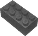
Height is the simplest property to identify. It’s the vertical distance between the top and bottom of the basic brick. Width, by convention, is the shorter of the two dimensions which lie on the horizontal plane (length is the other one). Both width and length are expressed in terms of studs, also called LEGO units. Knowing this, we can describe the measurements of the most traditional brick, the one whose first appearance dates back to 1949, which is 2 × 4 × 1 (see Figure 1.1).
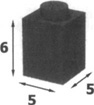
LEGO bricks, although their measurements are not expressed as such, are based on the metric system: A stud’s width corresponds to 8 mm and the height of a brick (minus the stud) to 9.6 mm. These figures are not important to remember. What’s important is that they do not have equal values, meaning you need two different units to refer to length and height. Their ratio is even more important: Dividing 9.6 by 8 you get 1.2 (the vertical unit corresponds to 1.2 times the horizontal one). This ratio is easier to remember if stated as a proportion between whole numbers: It is equivalent to 6:5. Figure 1.2 shows the smallest LEGO brick, described in LEGO units as a 1 × 1 × 1 brick. For the reasons explained previously, this LEGO “cube” is not a cube at all.
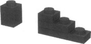
The LEGO system includes a class of components whose height is one-third of a brick. The most important element of this class is the plate, which comes in a huge variety of rectangular sizes, and in some special shapes too. If you stack three plates, you get the height of a standard brick (see Figure 1.3).
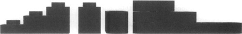
The advent of studless building has thrown a wrench into our understanding and use of the classic brick-and-plate-construction approaches. The new studless components provide a different way to construct LEGO models. The jury is still out regarding which method is better or more preferred—there are proponents on both sides of the fence with this. Figure 1.4 shows the traditional plates and bricks next to a newer TECHNIC beam and a set of three liftarms that are stacked, all to provide some reference on size. You will notice that their stacked heights are not compatible across the studded (left) and studless (right) parts.
The one thing that is undeniable is that LEGO has made a significant shift with its TECHNIC and MINDSTORMS lines toward studless components. If you are a die-hard studded builder, you are encouraged to take the plunge and try building studless. Many found the change in approach a challenge at first, but use it almost exclusively now. Studless building offers countless options for connectivity and even allows for building at odd angles that was difficult to accomplish with traditional beams.
Why do we care about all these relationships? To answer this, we must travel back to the late 1970s when the LEGO TECHNIC line was created. Up to that time, LEGO was designed and used to build things made of horizontal layers: Bricks and plates integrate pretty well when stacked together. Every child soon learns that three plates count for a brick, and this is all they need to know. But in 1977, LEGO decided to introduce a new line of products targeting an older audience: LEGO TECHNIC. It turned the common 1 × N brick holes into what we call a TECHNIC brick, or a beam(Figure 1.5, left). These holes allow axles to pass through them, and permit the beams to be connected to each other via pegs, thus creating a whole new world of possibilities.
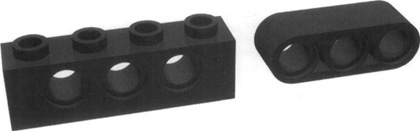
In the late 1990s, the advent of studless beams (Figure 1.5, right) opened the door to alternative building options. One of the best sets in TECHNIC history is undoubtedly the 8448 Super Street Sensation, which is built almost entirely from studless parts. LEGO was clever with its approach here. Instead of using beams to construct the chassis and plates to provide the “shell” or “form” for the model, the chassis was built using studless beams and its style was handled by fairing panels, allowing the curves of the car to “flow” with the design. LEGO did this to reduce costs: Less material required equals a cost savings in production. You can see a great example of this if you compare the 8448 Super Street Sensation to the classic TECHNIC 8880 Supercar. Compare their approaches to construction, and their weight. You will notice significant differences. The 8880 gets all its design cues from classic TECHNIC beams, whereas the 8448 uses fairings and flex axles for its design.
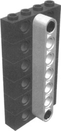
Suppose you want to mount a beam in a vertical position to brace two or more layers of horizontal beams. Here’s where you must remember the 6:5 ratio. The holes inside a beam are spaced at exactly the same distance as the studs, but are shifted over by half a stud. So, when we stand the beams up, the holes follow the horizontal units and not the vertical ones. Consequently, they don’t match the corresponding holes of the layered beams. In other words, the holes in the vertical beam cannot line up with the holes in the stack because of the 6:5 ratio. At least not with all the holes. But let’s take a closer look at what happens. Count the vertical units by multiples of 6 (6, 12, 18, 24, 30...) and the horizontal ones by multiples of 5 (5, 10, 15, 20, 25, 30...). Don’t count the starting brick and the starting hole—that is your reference point; you are measuring the distances from that point. You see? After counting five vertical units you reach 30, which is the same number you reach after counting six horizontal units (see Figure 1.6).
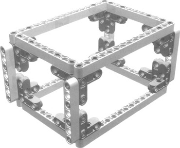
Now suppose you want to construct a robot that needs to be strong but light. With the studded beams, you would have to use a number of beams, plates, and pins to create the frame, and potentially you would need to cross-brace it. Depending on the approach taken, you may even use the aforementioned stacking technique, which would make your robot strong but heavy. With some of the newer parts that are now available, creating a strong and light chassis is quite simple and straightforward. Figure 1.7 shows a sample chassis that you could use as a base for your robot. It employs very few pieces, and in fact, it uses only four unique parts (in quantity) to make for a solid structure.
Who said that the LEGO beams must connect at a right angle to each other? The very nature of LEGO is to produce squared things, but with the advent of studless parts, diagonal connections are mainstream now, making our world a bit more varied and interesting, and giving us another tool for problem solving.
You now know that you can cross-connect a stack of plates and beams with another beam. And you know how it works in numerical terms. So how would you brace a stack of beams with a diagonal beam?
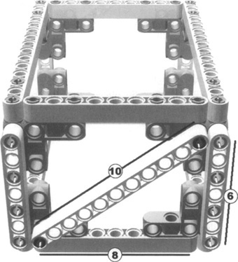
You must look at that diagonal beam as though it were the hypotenuse of a right-angled triangle. Continuing from the previous sample, Figure 1.8 adds a cross-brace to support the structure and provides a sample for this next bit. Now proceed to measure its sides, remembering not to count the first holes, because we measure lengths in terms of distances from them. The base of the triangle is eight holes. Its height is six holes: Remember that in a standardized grid, every horizontal beam is at a distance of two holes from those immediately below and above it. In regard to the hypotenuse, it counts 10 holes in length.
For those of you who have never been introduced to Pythagoras, the ancient Greek philosopher and mathematician, the time has come to meet him. In what is probably the most famous theorem of all time, Pythagoras demonstrated that there’s a mathematical relationship between the length of the sides of right-angled triangles. The sides composing the right angle are the catheti—let’s call them A and B. The diagonal is the hypotenuse—let’s call that C. The relationship is:
A2 + B2 = C2
Now we can test it with our numbers:
82 + 62= 102
This expands to:
(8 × 8) + (6 × 6) = (10 × 10)
64 + 36 = 100
100 = 100
Yes! This is exactly why the example works so well. It’s not by chance; it’s the good old Pythagorean theorem. Reversing the concept, you might calculate whether any arbitrary pair of base and height values brings you to a working diagonal. This is true only when the sum of the two lengths, each squared, gives a number that’s the perfect square of a whole number. Let’s try some examples (see Table 1.1).
Table 1.1. Verifying Working Diagonal Lengths
A (Base) | B (Height) | A2 | B2 | A2 + B2 | Comments |
|---|---|---|---|---|---|
5 | 6 | 25 | 36 | 61 | This doesn’t work. |
3 | 8 | 9 | 64 | 73 | This doesn’t work. |
3 | 4 | 9 | 16 | 25 | This works! 25 is 5 × 5. |
15 | 8 | 225 | 64 | 289 | This works too. Although 289 is 17 × 17, this would come out a very large triangle. |
9 | 8 | 81 | 64 | 145 | Note that 145 is not the square of a whole number, but it is so close to 144 (12 × 12) that if you try to make it your diagonal beam, it will fit with no effort at all. After all, the difference in length is less than 1 percent. |
At this point, you’re probably wondering whether you have to keep your pocket calculator on your desk when playing with LEGO, and maybe dig up your old high school math textbook to reread. Don’t worry; you won’t need either, for many reasons:
You won’t need to use diagonal beams very often.
Most of the useful combinations derive from the basic triad 3-4-5 (see the third line in Table 1.1). If you multiply each side of the triangle by a whole number, you still get a valid triad—by 2: 6-8-10, by 3: 9-12-15, and so on. These are by far the most useful combinations, and they are very easy to remember.
We provide a table in Appendix B with many valid side lengths, including some that are not perfect but so close to the right number that they will work very well without causing any damage to your bricks.
We suggest you take some time to play with triangles, experimenting with connections using various angles and evaluating their rigidity. This knowledge will prove precious when you start building complex structures.
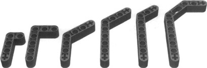
As noted earlier, over the past several years LEGO has introduced a number of new TECHNIC parts that divert from the concept of straight beams and 90-degree connectivity. We could review numerous parts here, but there simply is not enough room in the book for this. Some of the more popular ones fit in the common group of studless beams, called liftarms. They come in many shapes and sizes, you can use them to connect parts at differing angles, and you often see them in robot grabbers, fingers, ball casters, and so on. Figure 1.9 shows a sample of liftarms from the TECHNIC line.
Liftarms are quite versatile parts that often come to the rescue when you’re trying to connect components in odd ways. As you browse through the chapters of this book, keep an eye out for examples of this. You will see several samples that use liftarms in differing ways. Some use them to connect motors at odd angles, and others use them for bracing. Figure 1.10 shows some examples of how you can use liftarms to brace a structure.
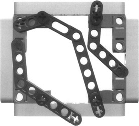
Using your own parts, try to re-create this sample. You will notice that you can connect the liftarms at only certain holes and angles; not every combination works. However, by using different types of liftarms, you can see how each one connects a little differently, thus providing a number of ways to brace your robot.
It is also important to think outside the box here. With many of the newer TECHNIC parts, your models do not have to follow the traditional square or rectangular building approach. For example, using Figure 1.10, you could extend one of the liftarms upward to mount a sensor, or use it to connect a servo motor to provide a drive mechanism mounted at an angle. Try to experiment with connecting liftarms and beams together and see how you can brace your structure or extend components of your robot at odd angles.
The important thing to remember here is that you don’t always have to follow the traditional approach of connecting beams and bricks at 90-degree angles.
Did you survive the geometry? You can see it doesn’t have to be that hard once you get familiar with the basics. First, it helps to know how to identify the beams by their proportions, counting the length and width by studs, and recognizing that the vertical unit to horizontal unit ratio is 6 to 5. Thus, according to the simple ratio, when you’re trying to find a locking scheme to insert axles or pins into perpendicular beam holes, you know that every five bricks in height, the holes of a crossed beam match up. Also, because three plates match the height of a brick, the most compact locking scheme is to use increments of two plates and a brick, because it gives you that magic multiple of 5. If you stay with this scheme, the standard grid, everything will come easy: one brick, two plates, one brick, two plates...
To fit a diagonal beam, use the Pythagorean theorem. Combinations based on the triad of 3-4-5 constitute a class of easy-to-remember distances for the beam to make a right triangle, but there are many others. You also were exposed to the TECHNIC liftarm, which offers countless connectivity options for your robots. Remember to think outside the box and not assume that you have to build via the traditional square or rectangular approach. Explore with the parts you have in your kit, and discover new ways to connect parts using studless building techniques. You will soon find that this way of building offers great flexibility in design.