CHAPTER 8
WIDE AREA NETWORKS
MOST ORGANIZATIONS do not build their own metropolitan or long-distance communication circuits, preferring instead to lease them from common carriers or to use the Internet. Therefore, this chapter focuses on the WAN architectures and telecommunications services offered by common carriers for use in WANs, not the underlying technology that the carriers use to provide them. We discuss the four principal types of WAN services that are available: circuit-switched services, dedicated-circuit services, packet-switched services, and virtual private network (VPN) services. We conclude by discussing how to improve WAN performance and how to select services to build WANs.
OBJECTIVES ![]()
- Understand circuit-switched services and architectures
- Understand dedicated-circuit services and architectures
- Understand packet-switched services and architectures
- Understand Internet-based VPN services and architectures
- Understand the best practice recommendations for WAN design
- Be familiar with how to improve WAN performance
CHAPTER OUTLINE ![]()
8.2.2 Plain Old Telephone Service
8.2.3 Integrated Services Digital Network (ISDN)
8.3 DEDICATED-CIRCUIT NETWORKS
8.3.3 Synchronous Optical Network
8.4.2 Asynchronous Transfer Mode
8.4.5 Multi-Protocol Label Switching
8.6 THE BEST PRACTICE WAN DESIGN
8.7.1 Improving Device Performance
8.7.2 Improving Circuit Capacity
8.8 IMPLICATIONS FOR MANAGEMENT
8.1 INTRODUCTION
Wide area networks (WANs) typically run long distances connecting different offices in different cities or countries. Some WANs run much shorter distances, connecting different buildings in the same city. Most organizations do not own the land across which WANs are built, so instead they rent or lease circuits from common carriers—private companies such as AT&T, Bell Canada, Sprint, and BellSouth that provide communication services to the public. As a customer, you do not lease physical cables per se; you simply lease circuits that provide certain transmission characteristics. The carrier decides whether it will use twisted-pair, coaxial, fiber optics, or other media for its circuits.
Common carriers are profit oriented, and their primary products are services for voice and data transmissions, both over traditional wired circuits as well as cellular services. Common carriers often supply a broad range of computer-based services, such as the manufacturing and marketing of specialized communication hardware and software. A common carrier that provides local telephone services (e.g., BellSouth) is commonly called a local exchange carrier (LEC), whereas one that provides long-distance services (e.g., AT&T) is commonly called an interexchange carrier (IXC). As the LECs move into the long-distance market and IXCs move into the local telephone market, this distinction may disappear.
In this chapter, we examine the WAN architectures and technologies from the viewpoint of a network manager, rather than that of a common carrier. We focus less on internal operations and how the specific technologies work, and more on how these services are offered to network managers and how they can be used to build networks because network managers are less concerned with how the services work and more concerned with how they can use them effectively.
Likewise, we will focus on WAN services in North America because the majority of our readers are in North America. Although there are many similarities in the way data communications networks and services have evolved in different countries, there also are many differences. Most countries have a federal government agency that regulates data and voice communications. In the United States, the agency is the Federal Communications Commission (FCC); in Canada, it is the Canadian Radio-Television and Telecommunications Commission (CRTC). Each state or province also has its own public utilities commission (PUC) to regulate communications within its borders.
We will discuss three services that use common carrier networks (circuit-switched services, dedicated-circuit services, and packet-switched services) and one that uses the public Internet (virtual private network). The first three enable the customer to more precisely design and manage the WAN and offer more reliable services, so these services are most commonly chosen by large organizations that view the WAN as an important part of their business operations. The public Internet is usually much cheaper than these services, but less reliable, so it is usually only attractive to very small organizations that are more price sensitive.
8.2 CIRCUIT-SWITCHED NETWORKS
Circuit-switched networks are the oldest and simplest approach to WAN circuits. These services operate over the public switched telephone network (PSTN); that is, the telephone networks operated by the common carriers such as AT&T, BellSouth, and so on. When you telephone someone, you are using the PSTN. The first service we discuss is the dial-up service you use when you call an ISP with a dial-up modem—but first we need to discuss the basic architecture shared by all circuit-switched services.
At this point, you're probably wondering who uses dial-up any more? And you'd be right. About 40% of the U.S. population in 2001 used dial-up services, but today that has dropped to about 5%. However, many organizations still use dial-up services for specialty services such as videoconferencing, although we expect these also will fade in time.
8.2.1 Basic Architecture
Circuit-switched services use a cloud architecture. The users lease connection points (e.g., telephone lines) into the common carrier's network, which is called the cloud 1(Figure 8.1). A person (or computer) dials the telephone number of the destination computer and establishes a temporary circuit between the two computers. The computers exchange data, and when the task is complete, the circuit is disconnected (e.g., by hanging up the phone).
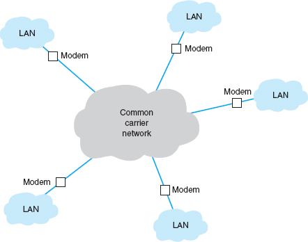
FIGURE 8.1 Dialed circuit services. LAN = local area network
This architecture is very flexible. Circuits can be established as needed between any computers attached to the cloud at any point. However, data can be transmitted only while a circuit is established, and only to the one location it connects to. If a computer needs to send data to a number of other locations, a series of temporary circuits must be established with and later disconnected from each location, one after another. In general, only a limited number of circuits can be established from or to any one location at a time (e.g., each location has only so many telephone lines).
Cloud-based designs are simpler for the organization because they move the burden of network design and management inside the cloud from the organization to the common carrier. Network managers do not need to worry about the amount of traffic sent between each computer; they just need to specify the amount of traffic entering and leaving each computer and buy the appropriate size and number of connections into the PSTN. However, this comes at a price. Cloud-based designs can be more expensive because users must pay for each connection into the network and pay on the basis of the amount of time each circuit is used. Cloud-based designs are often used when network managers are uncertain of network demand, particularly in a new or rapidly growing network.
There are two basic types of switched-circuit services in use today: POTS and ISDN.
8.2.2 Plain Old Telephone Service
Plain old telephone service (POTS) is the name for the dial-up services you or your parents used at one time. To use POTS, you need to lease a circuit into the network (i.e., a telephone line) and install special equipment (i.e., a modem) to enable your computer to talk to the PSTN. To transfer data to and from another computer on the network, you instruct your modem to dial the other computer's telephone. Once the modem in your computer connects to the modem at the other end, you can transfer data back and forth. When you are done, you hang up and can then call another computer if you wish. Today, POTS is most commonly used to connect to the Internet, but you can also use it to communicate directly with a private non-Internet server.
Plain old telephone service may use different circuit paths between the two computers each time a number is dialed. Some circuits have more noise and distortion than others, so the quality and maximum data transmission rate can vary. Typical data rates are between 33 kbps and 56 kbps.
8.2.3 Integrated Services Digital Network (ISDN)
The first generation of integrated services digital network (ISDN) combines voice, video, and data over the same digital circuit. Because there is a newer version of ISDN, the original version is occasionally called narrowband ISDN, but we will just use the term ISDN. ISDN is widely available from a number of common carriers in North America.
To use ISDN, users first need to lease connection points in the PSTN, which are telephone lines just like POTS. Next, they must have special equipment to connect their computers (or networks) into the PSTN. Users need an ISDN network terminator (NT-1 or NT-2) that functions much like a hub, and a NIC (called a terminal adapter [TA] or even an “ISDN modem”) in all computers attached to the NT-1/NT-2. In most cases, the ISDN service appears identical to the regular dialed telephone service, with the exception that usually (but not always) each device attached to the NT-1/NT-2 needs a unique service profile identifier (SPID) to identify it. To connect to another computer using ISDN, you dial that computer's telephone number using the ISDN NIC in much the same way as you would with a modem on a regular telephone line. There are two types of ISDN, which we will discuss next.
Basic Rate Interface Basic rate interface (BRI) (sometimes called basic access service or 2B +D) provides a communication circuit with two 64-Kbps digital transmission channels (called B channels) and one 16-Kbps control signaling channel (called a D channel). The two B channels handle digitized voice, data, and image transmissions, providing a total of 128 Kbps. The D channel is used for control messages such as acknowledgments, call setup and termination, and other functions such as automatic number identification. Some common carriers sell just one single 64-Kbps channel to those customers needing less capacity than full BRI.
Primary Rate Interface Primary rate interface (PRI) (also called primary access service or 23B +D) is typically offered to commercial customers. It consists of 23 64-Kbps B channels plus 1 64-Kbps D channel. PRI has almost the same capacity as a T1 circuit (1.544 Mbps). In Europe, PRI is defined as 30 B channels plus 1 D channel, making interconnection between America and Europe difficult.
8.3 DEDICATED-CIRCUIT NETWORKS
There are two main problems with POTS and ISDN circuit-switched networks. First, each time you want to transfer data, you need to make a separate connection. Second, the data rates on these circuits are low, ranging from 56 Kbps for dialed POTS circuits to 128 Kbps or 1.5 Mbps for ISDN circuits. One alternative is to establish a dedicated-circuit network, in which the user leases circuits from the common carrier for his or her exclusive use 24 hours per day, 7 days per week. Dedicated-circuit networks are sometimes called private line services.
8.3.1 Basic Architecture
With a dedicated-circuit network, you lease circuits from common carriers. All connections are point to point, from one building in one city to another building in the same or a different city. The carrier installs the circuit connections at the two end points of the circuit and makes the connection between them. The circuits still run through the common carrier's cloud, but the network behaves as if you have your own physical circuits running from one point to another (Figure 8.2).
Once again, the user leases the desired circuit from the common carrier (specifying the physical end points of the circuit) and installs the equipment needed to connect computers and devices (e.g., routers or switches) to the circuit. This equipment may include multiplexers or a channel service unit (CSU) and/or a data service unit (DSU); a CSU/DSU is the WAN equivalent of a NIC in a LAN.
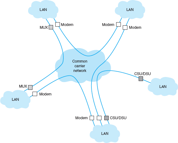
FIGURE 8.2 Dedicated-circuit services. CSU = channel service unit; DSU = data service unit; MUX = multiplexer
Unlike circuit-switched services that typically use a pay-per-use model, dedicated circuits are billed at a flat fee per month, and the user has unlimited use of the circuit. Once you sign a contract, making changes can be expensive because it means rewiring the buildings and signing a new contract with the carrier. Therefore, dedicated circuits require more care in network design than do switched circuits, both in terms of locations and the amount of capacity you purchase.
There are three basic architectures used in dedicated-circuit networks: ring, star, and mesh. In practice, most networks use a combination of architectures. For example, a distributed star architecture has a series of star networks that are connected by a mesh or ring architecture.
Ring Architecture A ring architecture connects all computers in a closed loop with each computer linked to the next (Figure 8.3). The circuits are full-duplex or half-duplex circuits, meaning that messages flow in both directions around the ring. Computers in the ring may send data in one direction or the other, depending on which direction is the shortest to the destination.
One disadvantage of the ring topology is that messages can take a long time to travel from the sender to the receiver. Messages usually travel through several computers and circuits before they reach their destination, so traffic delays can build up very quickly if one circuit or computer becomes overloaded. A long delay in any one circuit or computer can have significant impacts on the entire network.
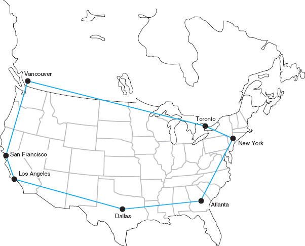
In general, the failure of any one circuit or computer in a ring network means that the network can continue to function. Messages are simply routed away from the failed circuit or computer in the opposite direction around the ring. However, if the network is operating close to its capacity, this will dramatically increase transmission times because the traffic on the remaining part of the network may come close to doubling (because all traffic originally routed in the direction of the failed link will now be routed in the opposite direction through the longest way around the ring).
Star Architecture A star architecture connects all computers to one central computer that routes messages to the appropriate computer (Figure 8.4). The star topology is easy to manage because the central computer receives and routes all messages in the network. It can also be faster than the ring network because any message needs to travel through at most two circuits to reach its destination, whereas messages may have to travel through far more circuits in the ring network. However, the star topology is the most susceptible to traffic problems because the central computer must process all messages on the network. The central computer must have sufficient capacity to handle traffic peaks, or it may become overloaded and network performance will suffer.
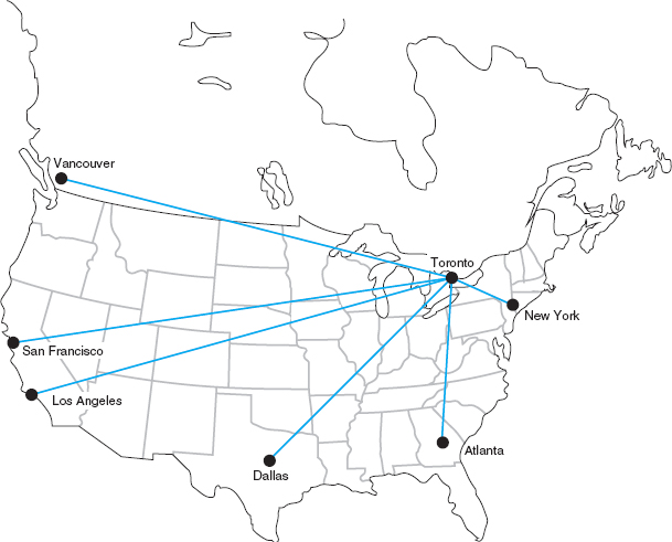
In general, the failure of any one circuit or computer affects only the one computer on that circuit. However, if the central computer fails, the entire network fails because all traffic must flow through it. It is critical that the central computer be extremely reliable.
Mesh Architecture In a full-mesh architecture, every computer is connected to every other computer (Figure 8.5a). Full-mesh networks are seldom used because of the extremely high cost. Partial-mesh architecture (usually called just mesh architecture), in which many, but not all, computers are connected, is far more common (Figure 8.5b). Most WANs use partial-mesh topologies.
The effects of the loss of computers or circuits in a mesh network depend entirely on the circuits available in the network. If there are many possible routes through the network, the loss of one or even several circuits or computers may have few effects beyond the specific computers involved. However, if there are only a few circuits in the network, the loss of even one circuit or computer may seriously impair the network.
In general, mesh networks combine the performance benefits of both ring networks and star networks. Mesh networks usually provide relatively short routes through the network (compared with ring networks) and provide many possible routes through the network to prevent any one circuit or computer from becoming overloaded when there is a lot of traffic (compared with star networks in which all traffic goes through one computer).
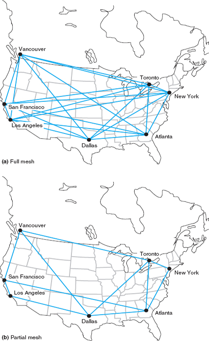
The drawback is that mesh networks use decentralized routing so that each computer in the network performs its own routing. This requires more processing by each computer in the network than in star or ring networks. Also, the transmission of network status information (e.g., how busy each computer is) “wastes” network capacity.
There are two types of dedicated-circuit services in common use today: T carrier services and synchronous optical network (SONET) services. Both T carrier and SONET have their own data link protocols, which are beyond the focus of this chapter.
8.3.2 T Carrier Services
T carrier circuits are the most commonly used form of dedicated-circuit services in North America today. As with all dedicated-circuit services, you lease a dedicated circuit from one building in one city to another building in the same or different city. Costs are a fixed amount per month, regardless of how much or how little traffic flows through the circuit. There are several types of T carrier circuits as shown in Figure 8.6, but only T1 and T3 are in common use today.
A T1 circuit (also called a DS1 circuit) provides a data rate of 1.544 Mbps. T1 circuits can be used to transmit data but often are used to transmit both data and voice. In this case, inverse TDM provides 24 64-Kbps circuits.2 Digitized voice using PCM requires a 64-Kbps circuit (see Chapter 3), so a T1 circuit enables 24 simultaneous voice channels. Most common carriers make extensive use of PCM internally and transmit most of their voice telephone calls in digital format using PCM, so you will see many digital services offering combinations of the standard PCM 64-Kbps circuit.
A T3 circuit allows transmission at a rate of 44.736 Mbps although most articles refer to this rate as 45 megabits per second. This is equal to the capacity of 28 T1 circuits. T3 circuits are becoming popular as the transmission medium for corporate MANs and WANs because of their higher data rates. Although T2 and T4 circuits are defined standards, they are not commercially available and therefore we don't discuss them here.
Fractional T1, sometimes called FT1, offers portions of a 1.544-Mbps T1 circuit for a fraction of its full cost. Many (but not all) common carriers offer sets of 64 Kbps DS-0 channels as FT1 circuits. The most common FT1 services provide 128 Kbps, 256 Kbps, 384 Kbps, 512 Kbps, and 768 Kbps.
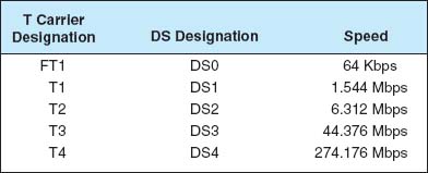
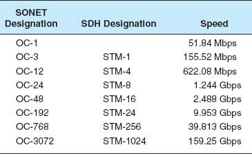
FIGURE 8.7 SONET (synchronous optical network) and SDH (synchronous digital hierarchy) services. OC = optical carrier (level)
8.3.3 Synchronous Optical Network
The synchronous optical network (SONET) is the American standard (ANSI) for high-speed dedicated-circuit services. The ITU-T recently standardized an almost identical service that easily interconnects with SONET under the name synchronous digital hierarchy (SDH).
SONET transmission speeds begin at the OC-1 level (optical carrier level 1) of 51.84 Mbps. Each succeeding rate in the SONET fiber hierarchy is defined as a multiple of OC-1, with SONET data rates defined as high as 160 Gbps. Figure 8.7 presents the commonly used SONET and SDH services. Each level above OC-1 is created by an inverse multiplexer. Notice that the slowest SONET transmission rate (OC-1) of 51.84 Mbps is slightly faster than the T3 rate of 44.376 Mbps.
8.4 PACKET-SWITCHED NETWORKS
Packet-switched networks are quite different from the two types of networks discussed previously. For both circuit-switched and dedicated-circuit networks, a circuit was established between the two communicating computers. This circuit provided a guaranteed data transmission capability that was available for use by only those two computers. In contrast, packet-switched services enable multiple connections to exist simultaneously between computers over the same physical circuit, just like LANs and BNs.
8.1 CLEVELAND TRANSIT
MANAGEMENT FOCUS
The Greater Cleveland Regional Transit Authority (GCRTA) has about 2400 employees and provides bus, trolley, and rail service to about 1.3 million people in the Cleveland area. It has many office locations throughout the region, and more than half of its employees are on the move as they work.
A recent blackout highlighted how vulnerable GCRTA was to network outages. Communications were knocked out, including systems supporting the Transit police.
GCRTA redesigned its WAN to use a SONET ring. SONET provides high-speed data services and the ring topology ensure maximum reliability. Even if one part of the ring is knocked out, whether by power failures or someone accidentally cutting a line, the network will continue to operate.
__________
SOURCE: “Staying on Track,” Case Study, AT&T, 2008.
8.4.1 Basic Architecture
With packet-switched services, the user again buys a connection into the common carrier cloud (Figure 8.8). The user pays a fixed fee for the connection into the network (depending on the type and capacity of the service) and is charged for the number of packets transmitted.
The user's connection into the network is a packet assembly/disassembly device (PAD), which can be owned and operated by the customer or by the common carrier. The PAD converts the sender's data into the network layer and data link layer packets used by the packet network and sends them through the packet-switched network. At the other end, another PAD reassembles the packets back into the network layer and data link layer protocols expected by the destination and delivers it to the appropriate computer.
One of the key advantages of packet-switched services is that different locations can have different connection speeds into the common carrier cloud. The PAD compensates for differences in transmission speed between sender and receiver; for example, the circuit at the sender might be 1.5 Mbps whereas the receiver only has a 64-Kbps circuit. In contrast, a dial-up circuit or a dedicated circuit must have the same speed at both the sender and receiver.
Packet-switched networks enable packets from separate messages with different destinations to be interleaved for transmission, unlike switched circuits and dedicated circuits. Packet switching is popular because most data communications consist of short bursts of data with intervening spaces that usually last longer than the actual burst of data. Packet switching takes advantage of this characteristic by interleaving bursts of data from many users to maximize use of the shared communication network. Figure 8.9 shows a packet-switching connection between six different cities. The little boat-shaped figures (shown on the communication circuits) represent individual packets from separate messages.
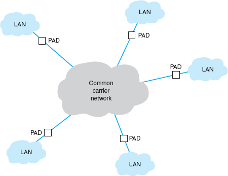
FIGURE 8.8 Packet-switched services. LAN = local area network; PAD = packet assembly/disassembly device
Although the packets in one data stream may mix with several other data streams during their journey, it is unlikely that packets from two different data streams will travel together during the entire length of their transmission. The two communicating computers do not need to know through which intermediate devices their data are routed because the packet network takes care of it by either of two methods.
The first method, called datagram, is a connectionless service. It adds a destination address and sequence number to each packet, in addition to information about the data stream to which the packet belongs. In this case, a route is chosen for each packet as it is accepted into the packet network. Each packet may follow a different route through the network. At the destination address, the sequence number tells the network how to reassemble the packets into a continuous message. The sequence number is necessary because different routes may deliver packets at different speeds, so data packets often arrive out of sequence. Few networks today use datagrams for data transfer.
The second and more common routing method is a connection-oriented approach called a virtual circuit. In this case, the packet-switched network establishes what appears to be one end-to-end circuit between the sender and receiver. All packets for that transmission take the same route over the virtual circuit that has been set up for that particular transmission. The two computers believe they have a dedicated point-to-point circuit, but in fact, they do not.
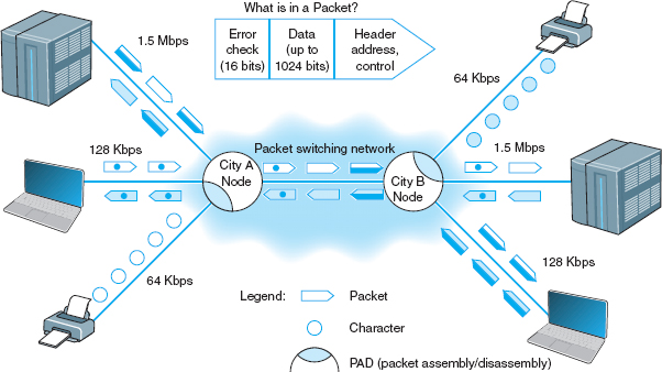
FIGURE 8.9 Packet-switching concepts
Virtual circuits are usually permanent virtual circuits (PVCs), which means that they are defined for frequent and consistent use by the network. They do not change unless the network manager changes the network. Some common carriers also permit the use of switched virtual circuits (SVCs) although this is not common. Changing PVCs is done using software, but common carriers usually charge each time a PVC is established or removed.
Because most network managers build packet-switched networks using PVCs, most packet-switched networks behave like dedicated-circuit networks. At first glance, the basic architecture in Figure 8.8 looks very similar to the cloud mesh of switched-circuit services, and in fact, they are very similar because data can move from any computer attached to the cloud to any other on the cloud. However, because virtually all data-intensive networks use PVCs, this means that the network is actually built using virtual circuits that are the software equivalent of the hardware-based dedicated circuits. As a result, packet-switched networks often have star, ring, and mesh topologies similar to those of dedicated-circuit networks. However, because the PVCs are in software, they are much easier to change than the hardware circuits of dedicated-circuit networks.
Most common carriers permit users to specify two different types of data rates that are negotiated per connection and for each PVC as it is established. The committed information rate (CIR) is the data rate the PVC must guarantee to transmit. If the network accepts the connection, it guarantees to provide that level of service. Most connections also specify a maximum allowable rate (MAR), which is the maximum rate that the network will attempt to provide, over and above the CIR. The circuit will attempt to transmit all packets up to the MAR, but all packets that exceed the CIR are marked as discard eligible (DE). If the network becomes overloaded, DE packets are discarded. So although users can transmit more data than the CIR, they do so at a risk of lost packets and the need to retransmit them.
Packet-switched services are often provided by different common carriers than the one from which organizations get their usual telephone and data services. Therefore, organizations often lease a dedicated circuit (e.g., T1) from their offices to the packet-switched network point of presence (POP). The POP is the location at which the packet-switched network (or any common carrier network, for that matter) connects into the local telephone exchange.
There are four types of packet-switched services: ATM, frame relay, IP/MPLS, and Ethernet services. Several common carriers (e.g., Sprint) have announced that they intend to stop offering all services except MPLS (Multi-protocol label switching), Ethernet, and Internet services (see Chapter 9). Other carriers have hinted at the same decision. Over the next few years these technologies may disappear.
8.4.2 Asynchronous Transfer Mode
Asynchronous transfer mode (ATM) works in much the same way as the Ethernet and TCP/IP networks we have discussed in previous chapters. However, ATM uses different layer-2 and layer-3 protocols. ATM has its own layer-3 protocol but typically uses SONET at layer 2. ATM usually performs encapsulation, which means that packets that enter an ATM network have their Ethernet frame preserved. This Ethernet frame is surrounded (not replaced) by an ATM layer-3 packet and a SONET frame which are used to move them through the ATM network. When the packet arrives at the destination and leaves the ATM network, the ATM packet and SONET frame are stripped off and the original Ethernet frame is delivered unchanged into the destination network.
Second, ATM provides no error control in the network; error control is the responsibility of the source and destination. (ATM is considered an unreliable packet service.) Because the user's data link packet remains intact, it is simple for the devices at the edge of the ATM network to check the error-control information in the packet to ensure that no errors have occurred and to request transmission of damaged or lost packets.
Third, ATM provides extensive QoS information that enables the setting of very precise priorities among different types of transmissions: high priority for voice and video, lower priority for e-mail.
Finally, ATM is scalable; it is easy to multiplex basic ATM circuits into much faster ATM circuits. Most common carriers offer ATM circuits that provide the same data transmission rates as SONET: 51.84 Mbps, 466.56 Mbps, 622.08 Mbps, and so on up to 39 Gbps (OC-768). New versions called T1 ATM (1.544 Mbps) and T3 ATM (45 Mbps) are also available.
8.4.3 Frame Relay
Frame relay, just recently standardized, transmits data slower than ATM so it has sometimes been called a poor man's ATM. It is one of the most commonly used WAN services in the world. Like ATM, frame relay performs encapsulation of packets, so packets are delivered unchanged through the network. Like ATM, it is an unreliable packet service because it does not perform error control. Frame relay checks for errors but simply discards packets with errors. It is up to the software at the source and destination to control for lost messages.
Frame relay does not yet provide QoS capabilities, but this is under development. Different common carriers offer frame relay networks with different transmission speeds. Most offer a range of CIR speeds that include 56 Kbps, 128 Kbps, 256 Kbps, 384 Kbps, 1.5 Mbps, 2 Mbps, and 45 Mbps.
8.2 FRAME RELAY AT AIR CHINA
MANAGEMENT FOCUS
Air China is the largest airline in China, both in terms of traffic and assets. The airline has over 200 aircraft that serve 81 domestic and 42 international destinations, with about 6000 scheduled flights per week. The airline industry has become more competitive due to China's rapid economic growth, so the airline sought to improve is global WAN.
Air China needed a strong global network to link its headquarters in Beijing with its 40 offices in Asia, Europe, the Middle East, Africa, and North America. It partnered with AT&T to provide an IP-based network running over frame relay in all countries. For local equipment, they choose Cisco routers and PADs to connect into the network.
___________
SOURCE: “Managed Networking Solutions Offer Competitive Advantage for China's Largest Global Airline,” Case Study, AT&T, 2008.
8.4.4 Ethernet Services
Although we have seen rapid increases in capacities and sharp decreases in costs in LAN and BN technologies, changes in WAN services offered by common carriers saw only modest changes in the 1990s. That changed in 2000 with the introduction of several Internet startups (e.g., Yipes) offering Ethernet services.
Most organizations today use Ethernet and IP in the LAN and BN environment, yet the WAN packet network services (ATM and frame relay) discussed earlier use different layer-2 protocols. Any LAN or BN traffic, therefore, must be translated or encapsulated into a new protocol and destination addresses generated for the new protocol. This takes time, slowing network throughput. It also adds complexity, meaning that companies must add staff knowledgeable in the different WAN protocols, software, and hardware these technologies require. This is one reason many common carriers are starting to call these technologies “legacy technologies,” signaling their demise.
Each of the preceding packet services uses the traditional PSTN provided by the common carriers such as AT&T and BellSouth. In contrast, Ethernet services bypass the PSTN; companies offering Ethernet services have laid their own gigabit Ethernet fiber-optic networks in large cities. When an organization signs up for service, the packet network company installs new fiber-optic cables from their citywide backbone into the organization's office complex and connects it to an Ethernet switch. The organization simply plugs its network into its Ethernet switch and begins using the service. All traffic entering the packet network must be Ethernet, using IP.
A Day in the Life: Networking and Telecommunications Vice President
A vice president is a person in an executive-level position whose focus is to set the strategic direction for the organization. A vice president has very little to do with the day-to-day operations; much like an Admiral in a Navy fleet, he or she defines the direction, but the individual captains running each ship actually make sure that everything that needs to happen gets done.
The vice president works with the chief information officer (CIO) and other executive leadership of the organization to identify the key organizational goals that have implications for the network. The vice president works with his or her staff to revise the strategic networking plan to ensure that the network is capable of supporting the organization's goals. The key elements of the strategic plan are the networking architectures, key technologies, and vendors. Once the strategy has been set, the vice president's job is to instruct the senior managers to execute the strategy and then let them do their jobs.
In most cases, the changes to the networking strategic plan are relatively minor, but sometimes there are dramatic changes that require a major shift in strategic direction. For example, in recent years, we've seen a major change in the fundamental capabilities of network tools and applications. Our architecture strategy during the 1990s was driven by the fact that network management tools were poor and maintenance costs per server were high; the fundamental architecture strategy was to minimize the number of servers. Today, network management tools are much better, maintenance costs per server are significantly lower, and network traffic has changed both in volume and in the number and complexity of services supported (e.g., Web, email, H.323, IPv6); the strategy today is to provide a greater number of servers, each of which is dedicated to supporting one specific type of traffic.
With thanks to Brian Voss
Currently, Ethernet services offer CIR speeds of 1 Mbps to 40 Gbps, in 1-Mbps increments at a lower cost than traditional packet-switched networks. Because this is an emerging technology, we should see many changes in the next few years.
8.4.5 Multi-Protocol Label Switching
Multi-protocol label switching (MPLS) is another relatively new WAN technology that has the potential to dramatically change WAN services. MPLS is designed to work with a variety of commonly used layer-2 protocols. It is sometimes called a layer-2.5 technology because it inserts 4-byte header that contains its own information between the layer-2 frame and the layer-3 IP packet.
With MPLS, the customer connects to the common carrier's network using any common layer-2 service (e.g., T carrier, SONET, ATM, frame relay, Ethernet). The carrier's switch at the network entry point examines the incoming frame and converts the incoming layer-2 or layer-3 address into an MPLS address label. This label and some other control information (e.g., quality of service) form the MPLS header, which is inserted into the layer-2 frame for transmission inside the carrier's network. The carrier can use the same layer-2 protocol inside its network as the customer, or it can use something different; for example, the customer could connect to the MPLS network using frame relay, but the carrier could use SONET inside its network.
The address in MPLS label is used to move through the frame through the carrier network until it reaches the edge of the network at the customer's destination. The MPLS switch at this exit point removes the MPLS header and delivers the packet into the customer's network using whatever layer-2 protocol the customer has used to connect into the carrier's network at this point (e.g., frame, T1).
8.3 MPLS AT CISCO
MANAGEMENT FOCUS
For years, Cisco Systems Inc. had supported its Europe/Middle East/Africa (EMEA) offices using ATM with a series of star networks connected to stars (called a hub-and-spoke design). The WAN core was three offices (London, Amsterdam, and Brussels) connected to each other in a full mesh using ATM OC-3 circuits. Each of these three offices was the center of a star network that connected to three other secondary star networks and 10 major sites (9 stars and 30 major sites in total). The 9 secondary stars connected a total of 85 other offices.
The network was at capacity and any time one of the three core offices (or one of the hubs of the secondary stars) needed to be taken down for maintenance, it shut down a major part of the network. Worse still, it looked like the London office would need to move to a new building, which meant significant rewiring of the network.
Cisco chose to implement a full mesh MPLS network to provide greater capacity and better flexibility. Each office is connected into the MPLS carrier's cloud with two separate MPLS circuits that are laid in physically separate routes to provide better reliability in case a circuit is accidentally cut. Each of the two circuits is sized for the needs of the specific office, ranging from 64 Kbps up to 45 Mbps. Since the three core offices no longer route traffic for the entire network, they don't need as much network capacity as they did with the hub and spoke design. The new network has significantly increased capacity, reliability and flexibility, while keeping costs about the same.
__________
SOURCE: “How Cisco IT in Europe Migrated to MPLS VPN WAN,” Cisco IT Case Study, Cisco, 2007.
One advantage of MPLS is that it operates faster than traditional routing. Therefore, MPLS-based networks operate slightly faster than other packet services. A second advantage is that common carriers in the United States and Canada typically have a different way of charging for MPLS services than for other packet services, so it is common to use a full mesh design in which every location is connected to every other location. Packets take fewer hops and thus less time to reach their destinations.
8.5 VIRTUAL PRIVATE NETWORKS
A virtual private network (VPN) provides the equivalent of a private packet-switched network over the public Internet.3 It involves establishing a series of PVCs that run over the Internet so that the network acts like a set of dedicated circuits over a private packet network.
8.5.1 Basic Architecture
With a VPN, you first lease an Internet connection at whatever access rate and access technology you choose for each location you want to connect. For example, you might lease a T1 circuit from a common carrier that runs from your office to your Internet Service Provider (ISP). You pay the common carrier for the circuit and the ISP for Internet access. Then you connect a VPN gateway (a specially designed router or switch) to each Internet access circuit to provide access from your networks to the VPN. The VPN gateways enable you to create PVCs through the Internet that are called tunnels (Figure 8.10).
The VPN gateway at the sender takes the outgoing packet and encapsulates it with a protocol that is used to move it through the tunnel to the VPN gateway on the other side. The VPN gateway at the receiver strips off the VPN packet and delivers the packet to the destination network. The VPN is transparent to the users; it appears as though a traditional packet-switched network PVC is in use. The VPN is also transparent to the ISP and the Internet as a whole; there is simply a stream of Internet packets moving across the Internet. VPN software is commonly used on home computers or laptops to provide the same secure tunnels to people working from offsite.
VPNs operate either at layer 2 or layer 3. A layer-2 VPN uses the layer-2 packet (e.g., Ethernet) to select the VPN tunnel and encapsulates the entire packet, starting with the layer-2 packet. Layer-2 tunneling protocol (L2TP) is an example of a layer-2 VPN. A layer-3 VPN uses the layer-3 packet (e.g., IP) to select the VPN tunnel and encapsulates the entire packet, starting with the layer-3 packet; it discards the incoming layer-2 packet and generates an entirely new layer-2 packet at the destination. IPSec is an example of a layer-3 VPN.
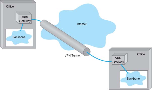
FIGURE 8.10 A virtual private network (VPN). ISP = Internet service provider
The primary advantages of VPNs are low cost and flexibility. Because they use the Internet to carry messages, the major cost is Internet access, which is inexpensive compared with the cost of circuit-switched services, dedicated-circuit services, and packet-switched services from a common carrier. Likewise, anywhere you can establish Internet service, you can quickly put in a VPN.
There are two important disadvantages. First, traffic on the Internet is unpredictable. Sometimes packets travel quickly, but at other times, they take a long while to reach their destination. Although some VPN vendors advertise QoS capabilities, these apply only in the VPN devices themselves; on the Internet, a packet is a packet. Second, because the data travel on the Internet, security is always a concern. Most VPN networks encrypt the packet at the source VPN device before it enters the Internet and decrypt the packet at the destination VPN device. (See Chapter 10 for more on encryption.)
8.5.2 VPN Types
Three types of VPNs are in common use: intranet VPN, extranet VPN, and access VPN. An intranet VPN provides virtual circuits between organization offices over the Internet. Figure 8.10 illustrates an intranet VPN. Each location has a VPN gateway that connects the location to another location through the Internet.
An extranet VPN is the same as an intranet VPN, except that the VPN connects several different organizations, often customers and suppliers, over the Internet.
An access VPN enables employees to access an organization's networks from a remote location. Employees have access to the network and all the resources on it in the same way as employees physically located on the network. The user uses VPN software on his or her computer to connect to the VPN device at the office. The VPN gateway accepts the user's log-in, establishes the tunnel, and the software begins forwarding packets over the Internet. An access VPN provides a less expensive connection than having a national toll-free phone number that connects directly into large sets of modems at the organization's office. Compared with a typical ISP-based remote connection, the access VPN is a more secure connection than simply sending packets over the Internet. Figure 8.11 shows an access VPN.
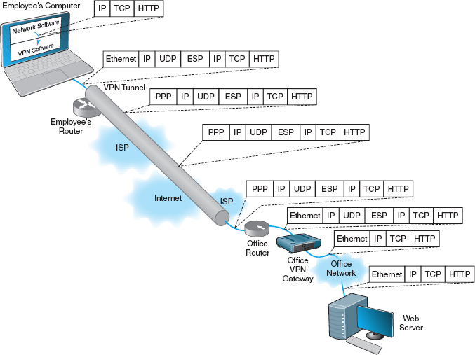
FIGURE 8.11 Using VPN Software
8.5.3 How VPNs Work
When packets move across the Internet, they are much like postcards in the paper mail. Anyone can read what they contain. VPNs provide security by encapsulating (i.e., surrounding) packets in a separate, secure packet that is encrypted. No one can read the encapsulated data without knowing the password that is used to decrypt the packet. Layer-2 and layer-3 VPNs work very similarly, except that layer-2 VPNs encapsulate the user's data starting with the layer-2 packet (the Ethernet frame) while layer-3 VPNs encapsulate the user's data starting with the layer-3 packet (the IP packet).
Figure 8.11 shows how a layer-3 access VPN using IPSec works. Suppose an employee is working at home with a LAN that uses a router to connect to the Internet via an Internet Service Provider (ISP) using DSL (we explain how DSL works in the next chapter). When the employee wants to use the VPN, he or she starts the VPN software on his or her computer and uses it to log-in to the VPN gateway at the office. The VPN software creates a new “interface” on the employee's computer that acts exactly like a separate connection into the Internet. Interfaces are usually hardware connections, but the VPN is a software interface, although the employee's computer doesn't know this—it's just another interface. Computers can have multiple interfaces; a laptop computer often has two interfaces, one for Ethernet and one for wireless Wi-Fi.
The VPN gateway at the office is also as a router and a DCHP server. The VPN gateway assigns an IP address to the VPN interface on the employee's computer that is an IP address in a subnet managed by the VPN gateway. For example, if the VPN gateway has an IP address of 156.56.198.1 and managed the 156.56.198.x subnet, it would assign an IP address in this subnet domain (e.g., 156.56.198.55).
The employee's computer now thinks it has two connections to the Internet: The traditional interface that has the computer's usual IP address and the VPN interface that has an IP address assigned by the VPN gateway. The VPN software on the employee's computer makes the VPN interface the default interface for all network traffic to and from the Internet, which ensures that all messages leaving the employee's computer flow through the VPN interface to the VPN gateway at the office.
Suppose the employee sends an HTTP request to a Web server at the office (or somewhere else on the Internet). The Web browser software will create an HTTP packet that is passed to the TCP software (which adds a TCP segment), and this in turn is passed to the IP software managing the VPN interface. The IP software creates the IP packet using the source IP address assigned by the VPN gateway. Normally, the IP software would then pass the IP packet to the Ethernet software that manages the Ethernet interface into the employee's LAN, but since the IP packet is being sent out the VPN interface, the IP packet is passed to the VPN software managing the VPN interface. Figure 8.11 shows the message as it leaves the network software and is passed to the VPN for transmission: an HTTP packet, surrounded by a TCP segment, surrounded by an IP packet.
The VPN software receives the IP packet, encrypts it, and encapsulates it (and its contents: the TCP segment, and the HTTP packet) with an Encapsulating Security Payload (ESP) packet using IPSec encryption. The contents of the ESP packet (the IP packet, the TCP segment, and the HTTP packet) are encrypted so that no one except the VPN gateway at the office can read them. You can think of the IPSec packet as an application layer packet whose destination is the office VPN gateway. How do we send an application layer packet over the Internet? Well, we pass it to the TCP software, which is exactly what the VPN software does.
The VPN software passes the ESP packet (and its encrypted contents) to the employee's computer normal Internet interface for transmission. This interface has been sitting around waiting for transmissions, but since the VPN interface is defined as the primary interface to use, it has received no messages to transfer except those from the VPN software.
This interface treats the ESP packet as an application layer packet that needs to be sent to the VPN gateway at the office. It attaches a transport layer packet (a UDP datagram in this case, not a TCP segment). It then passes the ESP packet to the IP software which creates an IP packet with an IP destination address of the VPN gateway at the office and a source IP of the employee's computer's normal Internet interface. It passes this IP packet to the Ethernet software, which adds an Ethernet frame and transmits it to the employee's router.
The employee's router receives the Ethernet frame, strips off the frame, and reads the IP packet. It sees that the packet needs to be sent to the VPN gateway at the office, which means sending the packet to the Employee's ISP over the DSL circuit. Since DSL uses PPP as its layer-2 protocol, it adds a PPP frame and sends the packet over the DSL circuit to the ISP.
The router at the ISP strips off the PPP frame and reads the IP packet, which it uses to route the packet through the Internet. As the packet moves over the Internet, the layer-2 frame changes at each hop, depending on the circuit in use. For example, if the ISP uses a T3 circuit, then the ISP creates an appropriate layer-2 frame to move the packet over the T3 circuit (which usually is a PPP frame).
The packet travels from the Internet to the ISP that connects the office to the Internet and arrives at the office's router. This router will strip off the incoming layer-2 frame (suppose the office uses a T-3 connection with PPP as shown in the figure), read the IP packet, and create an Ethernet frame that will send the packet to the office VPN gateway. The VPN gateway will strip off the Ethernet frame, read the IP packet, strip it off, read the UDP datagram, strip it off, and hand the ESP packet to its VPN software. The VPN gateway's software will decrypt the ESP packet, and deencapsulate the IP packet (and the TCP segment and HTTP packet it contains) from the ESP packet. The VPN gateway now has the IP packet (and the TCP segment and HTTP packet) that was originally created by the software on the employee's computer. The VPN gateway reads this IP packet and creates an Ethernet frame to send it on the next hop to its destination and transmits it into the office network, where it ultimately reaches the Web server. On this last leg of the journey after it leaves the VPN gateway, the packet is not encrypted and can be read like a normal packet on the Internet.
8.4 CISCO'S METRO ETHERNET
MANAGEMENT FOCUS
The Cisco Systems Inc. offices in San Jose, California, used four SONET OC-3 links provided by different common carriers. Cisco needed more capacity, so when one of the common carriers decided to discontinue its SONET services, Cisco decided to try metro Ethernet.
Cisco replaced one OC-3 with a 200 Mbps metro Ethernet circuit from AT&T. AT&T installed two parallel 1 Gbps fiber optic circuits from the Cisco office into the AT&T network in San Jose. Only one circuit is in use; the other is a backup in case the first circuit fails.
The circuit connects into the AT&T network through an edge switch whose job is to add MPLS tags to the incoming frames to route them through the AT&T network to their destination. Although the circuit is capable of supporting 1 Gbps of data, this switch limits the circuit capacity to ensure that the circuit does not use more than the 200 Mbps of data that Cisco has contracted for. Cisco's router into the AT&T network is also configured to only enable 200 Mps of data on this circuit. If Cisco needs more capacity, it can change its contract with AT&T and Cisco and AT&T will change the capacity setting on their switch and router.
The circuit has proven to be very reliable and now provides 200 Mbps at a lower cost than the previous OC-3 circuit. Cisco plans to convert the remaining OC-3 circuits to metro Ethernet in the coming years.
__________
SOURCE: “How Cisco Deployed a High-Speed WAN,” Cisco.com.
MANAGEMENT FOCUS
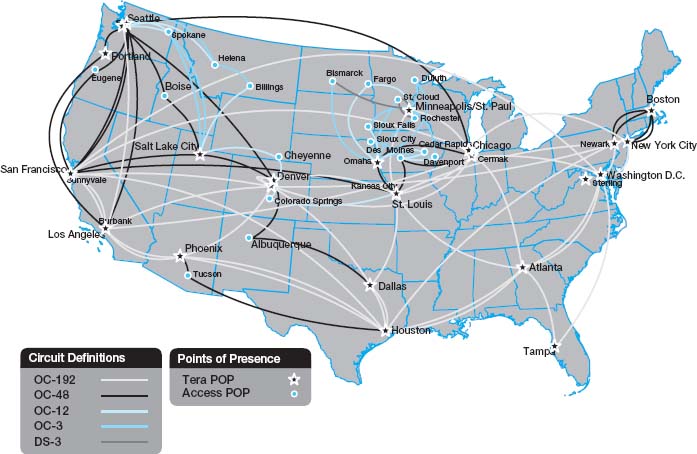
The Energy Sciences Network serves the U.S. Department of Energy and the thousands of corporate and university scientists doing research for it. It is one of the fastest wide area networks in the world because its users, researching high energy physics, human genomics, and climate modeling, routinely move terabyte-sized files across the network.
The current network uses a mixture of very high speed optical Ethernet services as well as high speed ATM, and moderate speed T3 circuits (see Figure 8.12). The Network has always been an early adopter of new technologies, so the San Francisco ring, currently running at 20 Gbps, will upgrade to 100 Gbps Ethernet within the next 2 years as it becomes available. Likewise, the older ATM portions of the network will gradually move to faster Ethernet services.
__________
SOURCE: “ESnet turns to high-speed optical MANs.” NetworkWorld, May 23, 2005, p. 12.
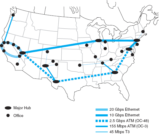
FIGURE 8.12 Energy Sciences Network
The return path from the Web server back to the employee's computer is very similar. The Web server will process the HTTP request packet and create an HTTP response packet which it sends back to the employee's computer. The source address on the IP packet that the Web server received was the IP address associated with the VPN interface on the employee's computer, so the Web server uses this address as the destination IP address. This packet is therefore routed back to the VPN gateway, because the subnet for this IP address is defined as being in the subnet that the VPN gateway manages. Once again, the return packet is not encrypted on this part of the journey.
When the packet arrives at the VPN gateway, it looks up the VPN IP address in its table and sees the usual IP address of the computer associated with that VPN address. The VPN gateway creates an ESP packet and encrypts the IP packet from the Web server (and the TCP segment and HTTP packet it contains). It then treats the ESP packet as a application layer packet that needs to be sent to the VPN software on the employee's computer; it passes it to its TCP software for a UDP datagram, then to its IP software for an IP packet, and then to its Ethernet software for an Ethernet frame and transmission back through the VPN tunnel.
When the packet eventually reaches the employee's computer, it comes in the normal Internet interface and eventually reaches the TCP software that strips off the UDP datagram. The TCP software sees that the ESP packet inside the UDP datagram is destined for the VPN software (remember that TCP port numbers are used to identify to which application layer software a packet should go). The VPN software removes the ESP packet and passes the IP packet it contains to the IP software, which in turn strips off the IP packet, and passes the TCP segment it contains to the TCP software, which strips off the TCP segments and passes the HTTP packet it contains to the Web browser.
8.6 THE BEST PRACTICE WAN DESIGN
Developing best practice recommendations for WAN design is more difficult than for LANs and backbones because the network designer is buying services from different companies rather than buying products. The relatively stable environment enjoyed by the WAN common carriers is facing sharp challenges by VPNs at the low end and Ethernet and MPLS services at the high end. As larger IT and equipment firms begin to enter the VPN and Ethernet services markets, we should see some major changes in the industry and in the available services and costs.
We also need to point out that the technologies in this chapter are primarily used to connect different corporate locations. Technologies primarily used for Internet access (e.g., DSL, cable modem) are discussed in the next chapter.
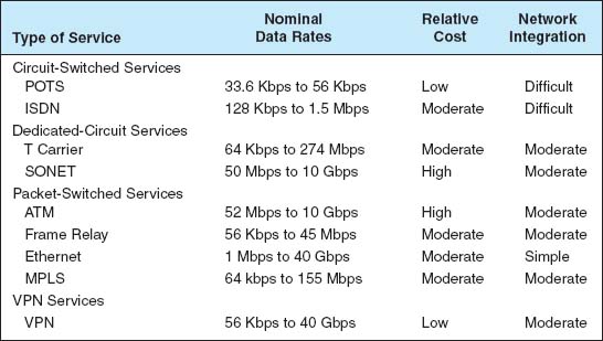
We use the same two factors as we have previously for LANs and backbones (effective data rates and cost), plus add one additional factor: network integration, which refers to the ease with which the WAN service can be used to connect LANs and backbones.
Figure 8.13 summarizes the major services available today for the WAN, grouped by the type of service. A few patterns should emerge from the table. For small WANs with low data transmission needs, VPN services are a reasonable alternative, provided the lack of reliability is not a major issue. Otherwise, frame relay is a good choice. See Figure 8.14.
For networks with moderate data transmission needs (64 Kbps–2 Mbps) there are several distinct choices. If cost is more important than reliability, then a VPN is probably a good choice. If you need flexibility in the location of your network connections and you are not completely sure of the volume of traffic you will have between locations, frame relay or MPLS are good choices. If you have a mature network with predictable demands, then T carrier services is probably a good choice or MPLS.
For high-traffic networks (2 Mbps–45 Mbps), the new Ethernet or MPLS services are a dominant choice. Some organizations may prefer the more mature—and therefore proven—T3 or frame relay services, depending on whether the greater flexibility of packet services provides value or a dedicated circuit makes more sense.
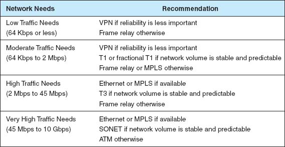
FIGURE 8.14 Best practice WAN recommendations
For very-high-traffic networks (45 Mbps–10 Gbps), Ethernet or MPLS services again are a dominant choice. And again some organizations may prefer the more mature ATM or SONET services, depending on whether the greater flexibility of packet services provides value or a dedicated circuit makes more sense.
Unless their data needs are stable, network managers often start with more flexible packet-switched services and move to the usually cheaper dedicated-circuit services once their needs have become clear and an investment in dedicated services is safer. Some packet-switched services even permit organizations to establish circuits with a zero-CIR (and rely entirely on the availability of the MAR) so network managers can track their needs and lease only what they need.
Network managers often add a packet network service as an overlay network on top of a network built with dedicated circuits to handle peak data needs; data usually travels over the dedicated-circuit network, but when it becomes overloaded with traffic, the extra traffic is routed to the packet network.
8.7 IMPROVING WAN PERFORMANCE
Improving the performance of WANs is handled in the same way as improving LAN performance. You begin by checking the devices in the network, by upgrading the circuits between the computers, and by changing the demand placed on the network (Figure 8.15).
8.7.1 Improving Device Performance
In some cases, the key bottleneck in the network is not the circuits; it is the devices that provide access to the circuits (e.g., routers). One way to improve network performance is to upgrade the devices and computers that connect backbones to the WAN. Most devices are rated for their speed in converting input packets to output packets (called latency). Not all devices are created equal; some vendors produce devices with lower latencies than others.
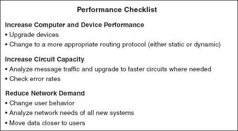
FIGURE 8.15 Improving performance of metropolitan and local area networks
8.6 GIGABIT ETHERNET IN THE NETHERLANDS
MANAGEMENT FOCUS
SURFnet is the national computer network for education and research in the Netherlands. Demand for network capacity had been rapidly growing as more and more students started using the Internet, so SURFnet began looking for a way to significantly upgrade its WAN that connects more than 50 universities, libraries, and research centers.
SURFnet considered implementing SONET or ATM OC-192, but felt that 10 Gbps Ethernet provided similar data rates, was more familiar to their customers, and was more scaleable. SURFnet has leased fiber from Amsterdam to major regional centers around the Netherlands (Figure 8.16). Each of these regional centers is a POP and in turn provides connections to other universities, libraries, and research centers in its region, often via a 1 Gbps or 100 Mbps Ethernet WAN. Sometimes SONET, ATM, or E-carrier services (the European equivalent to T carrier services) are used for the regional connections, depending upon the demand.
____________
SOURCE: “Cisco Helps SURFnet Provide 10 Gigabit Ethernet to Higher Education and Research Community,” www.cisco.com, 2004.
Another strategy is examining the routing protocol, either static or dynamic. Dynamic routing will increase performance in networks that have many possible routes from one computer to another and in which message traffic is “bursty”—that is, in which traffic occurs in spurts, with many messages at one time, and few at others. But dynamic routing imposes an overhead cost by increasing network traffic. In some cases, the traffic and status information sent between computers accounts for more than 50 percent of all WAN message traffic. This is clearly a problem because it drastically reduces the amount of network capacity available for users’ messages. Dynamic routing should use no more than 10 to 20 percent of the network's total capacity.
8.7.2 Improving Circuit Capacity
The first step is to analyze the message traffic in the network to find which circuits are approaching capacity. These circuits then can be upgraded to provide more capacity. Less-used circuits can be downgraded to save costs. A more sophisticated analysis involves examining why circuits are heavily used. For example, in Figure 8.3, the circuit from San Francisco to Vancouver may be heavily used, but much traffic on this circuit may not originate in San Francisco or be destined for Vancouver. It may, for example, be going from Los Angeles to Toronto, suggesting that adding a circuit here would improve performance to a greater extent than upgrading the San Francisco-to-Vancouver circuit.
The capacity may be adequate for most traffic but not for meeting peak demand. One solution may be to add a circuit-switched or packet-switched service that is used only when demand exceeds circuit capacity. The use of a service as a backup for heavy traffic provides the best of both worlds. The lower-cost dedicated circuit is used constantly, and the backup service is used only when necessary to avoid poor response times.
Sometimes a shortage of capacity may be caused by a faulty circuit. As circuits deteriorate, the number of errors increases. As the error rate increases, throughput falls because more messages have to be retransmitted. Before installing new circuits, monitor the existing ones to ensure that they are operating properly or ask the common carrier to do it.
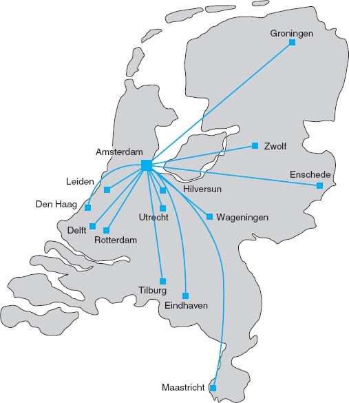
FIGURE 8.16 The SURFnet gigabit Ethernet WAN
8.7.3 Reducing Network Demand
There are many ways to reduce network demand. One simple step is to require a network impact statement for all new application software developed or purchased by the organization. This focuses attention on the network impacts at an early stage in application development. Another simple approach is to use data compression techniques for all data in the network.
Another sometimes more difficult approach is to shift network usage from peak or high-cost times to lower-demand or lower-cost times. For example, the transmission of detailed sales and inventory reports from a retail store to headquarters could be done after the store closes. This takes advantage of off-peak rate charges and avoids interfering with transmissions requiring higher priority such as customer credit card authorizations.
The network can be redesigned to move data closer to the applications and people who use them. This also will reduce the amount of traffic in the network. Distributed database applications enable databases to be spread across several different computers. For example, instead of storing customer records in one central location, you could store them according to region.
8.8 IMPLICATIONS FOR MANAGEMENT
As the amount of digital computer data flowing through and WANs has increased and as those networks have become increasingly digital, the networking and telecommunications vice president role has significantly changed over the past 10 years. Traditionally this vice president has been responsible for computer communications; today in most companies, this individual is also responsible for telephone and voice services.
T carrier, SONET, and ATM have traditionally dominated the WAN market. However, with the growing use of VPNs and Ethernet and MPLS services, we are beginning to see a major change. In the early 1990s, the costs of WANs were quite high. As these networks have changed to increasingly digital technologies, and as competition has increased with the introduction of new companies and new technologies (e.g., VPNs, Ethernet services), costs have begun to drop. More firms are now moving to implement software applications that depend on low-cost WANs.
The same factors that caused the LAN and BN to standardize on a few technologies (Ethernet, wireless Ethernet) are now acting to shape the future of the WAN. We believe that within five years, ATM will disappear and will be replaced by Ethernet and MPLS services. Within ten years, ISDN, T-carrier, and SONET may also disappear.
These changes have also had significant impacts on the manufacturers of networking equipment designed for WANs. Market shares and stock prices have shifted dramatically over the last five years in favor of companies with deep experience in backbone technologies (e.g., Ethernet) and Internet technologies (e.g., IP) as those technologies spread into the WAN market.
SUMMARY
Circuit-Switched Networks Circuit-switched services enable you to define the end points of the WAN without specifying all the interconnecting circuits through carrier's cloud. The user dials the number of the destination computer to establish a temporary circuit, which is disconnected when the data transfer is complete. POTS is traditional dial-up service. BRI ISDN provides a communication circuit with two 64-Kbps digital transmission channels and one 16-Kbps control channel. PRI ISDN consists of 23 64-Kbps data channels and one 64-Kbps control channel.
Dedicated-Circuit Networks A dedicated circuit is leased from the common carrier for exclusive use 24 hours per day, 7 days per week. Faster and more noise-free transmissions are possible, but you must carefully plan the circuits you need because changes can be expensive. The three common architectures are ring, star, and mesh. T carrier circuits have a set of digital services ranging from FT1 (64 Kbps) to T1 (1.544 Mbps) to T4 (274 Mbps). A SONET uses fiber optics to provide services ranging from OC-1 (51 Mbps) to OC-12 (622 Mbps).
Packet-Switched Networks Packet switching is a technique in which messages are split into small segments. The user buys a connection into the common carrier cloud and pays a fixed fee for the connection into the network and for the number of packets transmitted. ATM does not perform error control, and it offers data rates up to 622 Mbps. Frame relay, a newer packet-switching service with data rates up to 45 Mbps, does not perform error control. Ethernet services use Ethernet and IP to transmit packets at speeds between 1 Mbps and 1 Gbps.
VPN Networks MPLS supports a variety of protocols that can run faster than other types of services. A VPN provides a packet service network over the Internet. The sender and receiver have VPN devices that enable them to send data over the Internet in encrypted form through a VPN tunnel. Although VPNs are inexpensive, traffic delays on the Internet can be unpredictable.
The Best Practice WAN Design For small WANs with low data transmission needs, VPN or frame relay services are reasonable alternatives. For networks with moderate data transmission needs (64 Kbps–2 Mbps), a VPN is a good choice if cost is more important than reliability; otherwise, frame relay MPLS or T carrier services are good choices. For high-traffic networks (2 Mbps–45 Mbps), the new Ethernet services are a dominant choice, but some organizations may prefer the more mature—and therefore proven—T3 or frame relay services. For very high-traffic networks (45 Mbps–10 Gbps), Ethernet services are a dominant choice but again some organizations may prefer the more mature ATM or SONET services. Unless their data needs are stable, network managers often start with more flexible packet-switched services and move to the usually cheaper dedicated-circuit services once their needs have become clear and an investment in dedicated services is safer.
Improving WAN Performance One can improve network performance by improving the speed of the devices themselves and by using a better routing protocol. Analysis of network usage can show what circuits need to be increased or decreased in capacity, what new circuits need to be leased, and when additional switched circuits may be needed to meet peak demand. Reducing network demand may also improve performance. Including a network usage analysis for all new application software, using data compression, shifting usage to off-peak times, establishing priorities for some applications, or redesigning the network to move data closer to those who use it are all ways to reduce network demand.
KEY TERMS
access VPN
asynchronous transfer mode (ATM)
basic rate interface (BRI)
Canadian Radio-Television and Telecommunications Commission (CRTC)
channel service unit/data service unit (CSU/DSU)
circuit-switched services
cloud
cloud architecture
committed information rate (CIR)
common carrier
datagram
dedicated-circuit services
discard eligible (DE)
distributed star architecture
Ethernet services
Encapsulating Security Payload (ESP)
extranet VPN
Federal Communications Commission (FCC)
fractional T1 (FT1)
frame relay
full-mesh architecture
integrated services digital network (ISDN)
interexchange carrier (IXC)
Internet Service Provider (ISP)
intranet VPN
IPSec
L2TP
latency
layer-2 VPN
layer-3 VPN
local exchange carrier (LEC)
maximum allowable rate (MAR)
mesh architecture
multi-protocol label switching (MPLS)
narrowband ISDN
network terminator (NT-1, NT-2)
packet assembly/disassembly (PAD)
packet services
packet-switched networks
partial-mesh architecture
permanent virtual circuit (PVC)
plain old telephone service (POTS)
point of presence (POP)
primary rate interface (PRI)
public switched telephone network (PSTN)
public utilities commission (PUC)
ring architecture
service profile identifier (SPID)
star architecture
switched virtual circuit (SVC)
synchronous digital hierarchy (SDH)
synchronous optical network (SONET)
T carrier circuit
T1, T2, T3, T4 circuits
terminal adapter (TA)
2B+D
23B+D
virtual circuit
virtual private network (VPN)
VPN gateway
VPN software
QUESTIONS
- What are common carriers, local exchange carriers, and interexchange carriers?
- Who regulates common carriers and how is it done?
- Explain how a cloud architecture works.
- What is POTS?
- How does ISDN work?
- Compare and contrast BRI and PRI ISDN.
- What is a 2B+D?
- How does MPLS work?
- Compare and contrast circuit-switched services, dedicated-circuit services, and packet-switched services.
- Is a WAN that uses dedicated circuits easier or harder to design than one that uses dialed circuits? Explain.
- Compare and contrast ring architecture, star architecture, and mesh architecture.
- What are the most commonly used T carrier services? What data rates do they provide?
- Distinguish among T1, T2, T3, and T4 circuits.
- Describe SONET. How does it differ from SDH?
- How do packet-switching services differ from other WAN services?
- How is a virtual circuit distinguished from other circuits?
- Where does packetizing take place?
- What does a packet contain?
- What do you think the future of ISDN holds? Why?
- How do datagram services differ from virtual circuit services?
- How does an SVC differ from a PVC?
- Compare and contrast frame relay, ATM, and Ethernet services.
- Which is likely to be the longer-term winner: X.25, frame relay, ATM, MPLS, or Ethernet services?
- Explain the differences between CIR and MAR.
- How do VPN services differ from common carrier services?
- Explain how VPN services work.
- Compare the three types of VPN.
- How can you improve WAN performance?
- Describe five important factors in selecting WAN services.
- Are Ethernet services a major change in the future of networking or a technology blip?
- Are there any WAN technologies that you would avoid if you were building a network today? Explain.
- Suppose you joined a company that had a WAN composed of SONET, T carrier services, ATM, and frame relay, each selected to match a specific network need for a certain set of circuits. Would you say this was a well-designed network? Explain.
- It is said that packet-switched services and dedicated-circuit services are somewhat similar from the perspective of the network designer. Why?
EXERCISES
8-1. Find out the data rates and costs of T carrier services in your area.
8-2. Find out the data rates and costs of packet-switched and dedicated-circuit services in your area.
8-3. Investigate the WAN of a company in your area. Draw a network map.
8-4. Using Figure 8.11:
- Suppose the example used a layer-2 VPN protocol called L2TP. Draw the messages and the packets they would contain.
- Suppose the Web server was an email server. Draw the messages from the email server to the employee's computer. Show what packets would be in the message.
- Suppose the office connects to its ISP using metro Ethernet. What packets would be in the message from the office router to the ISP?
- Suppose the employee connects to the ISP using a layer-2 protocol called XYZ. What packets would be in the message from the employes's router to the ISP?
MINI-CASES
I. Cookies Are Us
Cookies Are Us runs a series of 100 cookie stores across the midwestern United States and central Canada. At the end of each day, the stores express-mail a diskette or two of sales and inventory data to headquarters, which uses the data to ship new inventory and plan marketing campaigns. The company has decided to move to a WAN. What type of a WAN architecture and WAN service would you recommend? Why?
II. MegaCorp
MegaCorp is a large manufacturing firm that operates 5 factories in Dallas, 4 factories in Los Angeles, and 5 factories in Albany, New York. It operates a tightly connected order management system that coordinates orders, raw materials, and inventory across all 14 factories. What type of WAN architecture and WAN service would you recommend? Why?
III. Sunrise Consultancy
Sunrise Consultancy is a medium-sized consulting firm that operates 17 offices around the world (Dallas, Chicago, New York, Atlanta, Miami, Seattle, Los Angeles, San Jose, Toronto, Montreal, London, Paris, Sao Paulo, Singapore, Hong Kong, Sydney, and Bombay). They have been using Internet connections to exchange email and files, but the volume of traffic has increased to the point that they now want to connect the offices via a WAN. Volume is low but expected to grow quickly once they implement a new knowledge management system. What type of a WAN topology and WAN service would you recommend? Why?
IV. CareGroup
Reread Management Focus 8.1. What other alternatives do you think that Cleveland Transit considered? Why do you think they did what they did?
Reread Management Focus 8.2. What other alternatives do you think that Air China considered? Why do you think they did what they did?
VI. CISCO Systems Inc.
Reread Management Focus 8.3. What alternatives do you think CISCO systems considered? Why do you think they did what they did?
VII. Energy Sciences Network
Reread Management Focus 8.5. What other alternatives do you think that the Energy Sciences Network considered? Why do you think they did what they did?
VIII. SURFnet
Reread Management Focus 8.6. What other alternatives do you think that SURFnet considered? Why do you think they did what they did?
CASE STUDY
NEXT-DAY AIR SERVICE
See the Web site.
HANDS-ON ACTIVITY 8A
Examining Wide Area Neworks
There are millions of WANs in the world. Some are run by common carriers and are available to the public. Others are private networks run by organizations for their internal use only. Thousands of these networks have been documented on the Web.
Explore the Web to find networks offered by common carriers and compare the types of network circuits they have. Now do the same for public and private organizations to see what they have. Figure 8.17 shows the network map for Quest (www-test.quest.com/largebusiness/enterprisesolutions/downloads/0703-NAIPMap207.pdf), a large common carrier in the United States. This shows the services offered in each major city, as well as the size of the circuits connecting cities.
Other interesting WAN maps, including dynamic maps, are available from: Cable and Wireless: www.cw.com/ournetwork/network maps
Cogent: www.cogentco.com/htdocs/map.php
Sprint/Nextel: www.sprintworldwide.com/english/maps/
TATA Communications: www.tatacommunications.com/map/gfp.html
Deliverable
Print three different WAN maps. For each map, identify the different types of circuits in use; for example, does the WAN use only T1 circuits or are there a mix of technologies in use?
HANDS-ON ACTIVITY 8B
Examining VPNs with Wireshark
If you want to see VPNs in action and understand how they protect your data as it moves over the Internet, you can sniff your packets with Wireshark. In order to do this lab, you'll have to have a VPN you can use. This will normally be available from your school.
In this exercise, you'll use Wireshark to sniff the packets with and without the VPN. Before you start, you'll need to download and install Wireshark, a packet sniffer software package, on your computer.
- Start the VPN software on your computer.
- Start a Web browser (e.g., Internet Explorer) and go to a Web site.
- Start Wireshark and click on the Capture menu item. This will open up a new menu (see the very top of Figure 8.18). Click on Interfaces.
- This will open a new window that will enable you to select which interface you want to capture packets from. Figure 8.18 shows you the three interfaces I have on my computer. The first interface is a dial-up modem that I never use. The second interface (labeled “Broadcom NetXtreme Gigabit Ethernet Driver”) is my Ethernet local area network. It has the IP address of 192.168.1.104. The third interface (labeled “WN (PPP/SLIP) Interface”) is the VPN tunnel; it has an IP address of 156.56.198.144 and only appears when you start the VPN software and log-in to a VPN gateway. If you do a WhoIs on this IP address (see Chapter 5 for WhoIs), you will see that this IP address is owned by Indiana University. When I logged into my VPN software, it assigned this IP address to the tunnel so that all IP packets that leave my computer over this tunnel will appear to be from a computer on a subnet on the Indiana University campus that is connected to the VPN gateway. Your computer will have different interfaces and IP addresses because your network is different than mine, but the interfaces should be similar.
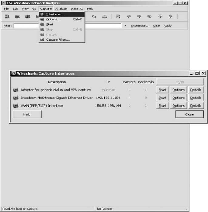
- Start by capturing packets on your regular Ethernet Interface. In my case, this is the second interface. Click on the Start button beside the Ethernet driver (which is 192.168.1.104 on my computer).
- Go to your Web browser and use it to load a new Web page, which will cause some packets to move through your network.
- A screen similar to that in Figure 8.19 will appear. After a few seconds, go back to Wireshark and click the Interface menu item and then click Stop.
- The top window in Figure 8.19 shows the packets that are leaving the computer through the tunnel. Click on a packet to look at it. The middle window in this figure shows what's inside the packet. We see an Ethernet frame, an IP packet, a UDP datagram, and an Encapsulating Security Payload packet (which is the ESP packet). Notice that you cannot see anything inside the ESP packet because its contents are encrypted. All packets in this tunnel will only flow to and from my computer (192.168.1.104) and the VPN gateway (156.56.245.15).
- Now we want to look at the packets that are sent by your computer into the VPN tunnel. No one else can see these packets. You can see them only because they are on your computer and you're looking at them as they move from your traditional network software to your VPN software.
- Click on the Wireshark Capture menu item and click Interfaces.
- Click on the Start button beside your VPN interface, which in my case in Figure 8.18 is the button in front of 156.56.198.144.
- Go to your Web browser and use it to load a new Web page, which will cause some packets to move through your network.
- A screen similar to that in Figure 8.20 will appear. After a few seconds, go back to Wireshark and click the Interface menu item, and then click Stop.
- The top window in Figure 8.20 shows the packets that are entering the VPN tunnel. Click on an HTTP packet to look at it (you may need to scroll to find one). The middle window in this figure shows what's inside the packet. We see an Ethernet frame, an IP packet, a TCP segment, and an HTTP request (for a page called/enterprise/on www.tatacommunications.com). We can see these because they have not yet entered the VPN software to be encrypted. These are the packets that would normally be sent over the Internet if we have not started the VPN software. Like all normal Internet messages, they can be read by anyone with sniffer software such as Wireshark.
Deliverables
- What layer-2, −3, and −4 protocols are used on your network to transmit an HTTP packet without a VPN?
- What layer-2, −3, and −4 protocols are used on your network to transmit an HTTP packet when your VPN is active?
- Look inside the VPN tunnel as was done in step 14. What layer-2, −3, and −4 protocols are used inside the encrypted packet?
HANDS-ON ACTIVITY 8C
Examining VPNs with Tracert
Tracert is a useful tool for seeing how VPNs affect routing. In order to do this lab, you'll have to have a VPN you can use. This will normally be available from your school.
Tracert is a simple command that comes preinstalled on all Windows and Mac computers. Tracert enables you to see the route that an IP packet takes as it moves over the Internet from one computer to another. Do this activity when you are not on campus.
- Tracert is command line command, so you first need to start the CMD window. Click Start, then Run, and then type CMD and press enter. This will open the command window, which is usually a small window with a black background. You can change the size and shape of this window, but it is not as flexible as a usual window.
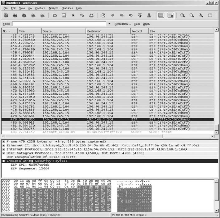
FIGURE 8.19 Viewing encrypted packets
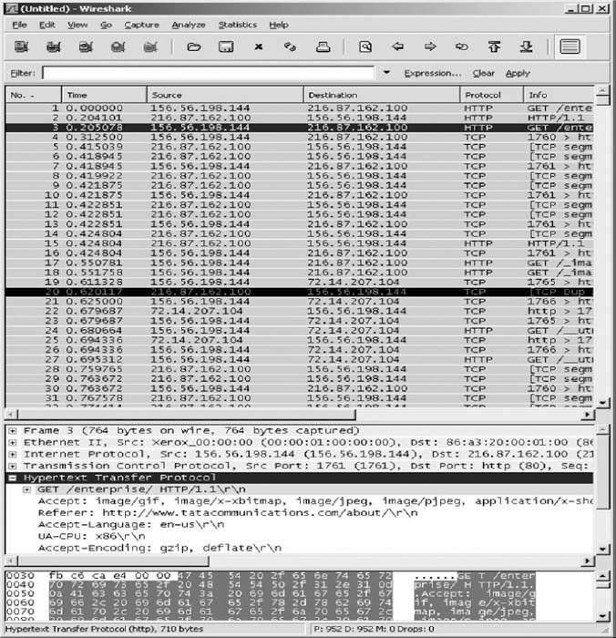
- We will first trace the route from your computers to two other computers without using the VPN. So make sure your VPN is not connected.
- We'll start by tracing the route from your computer to a computer on the campus of the site you VPN into. In my case, I VPN into my university, which is Indiana University. I can choose to trace the route to any computer on campus. I'll choose our main Web server (www.iu.edu). At the command prompt, type tracert and the URL of a computer on your campus.
- The top half of Figure 8.21 shows the route from my computer to www.iu.edu. There are 18 hops and it takes about 35 ms. The first hop does not report information because this feature is turned off in the router at my house for security reasons. You can see that my ISP is Comcast (hop 6). If you compare this to the tracert at the end of Chapter 5, you'll notice that my ISP changed (and thus the route into the Internet changed) between the time I wrote Chapter 5 and this chapter; Comcast bought Insight in my town of Bloomington, Indiana.
- Now trace the route from your computer to another computer on the Internet. The bottom of Figure 8.21 shows the route from my computer to www.google.com. There are 17 hops, and it takes about 35 ms. You'll see that the routes to IU and Google are the same until step 6, and then they diverge.
- Next we want to see what happens when you have a VPN connection. Start your VPN software and connect into the VPN gateway at your school.
- Trace the route from your computer to the same computer as in step 3. At the command prompt, type tracert and the URL of a computer on your campus.
- The top half of Figure 8.22 shows the route from my computer to www.iu.edu. There are two hops and it takes about 35 ms. The VPN is in operation and is transparent to my networking software, which thinks it is on the same subnet as the VPN gateway. Therefore, it thinks there is just one hop from my computer to the subnet's gateway, the VPN gateway. You'll see that the time is still about 35 ms, so the packet is still traveling the same 18 hops to get there; it's just that the tracert packet is encapsulated and doesn't see all the hops through the VPN tunnel.
- Now do a tracert to the same computer as you did in step 5. The bottom of Figure 8.22 shows the route from my computer to www.google.com. There are nine hops and it takes about 43 ms. Of course, the first hop is really 17 hops and 35 ms; this is again hidden from view. As we explained in the text, when the VPN is connected, all packets go from your computer to the VPN gateway on your campus before being routed to the final destination. You can see from this figure that this adds additional hops and time to packets that are not going to your campus, compared to not using the VPN. You can also see that once the packets leave the VPN gateway they are ordinary packets; they are no longer encrypted and protected from view.
The VPN provides security only to and from the VPN gateway on your campus, not beyond it. Therefore, you should use your VPN if you have security concerns to and from campus (e.g., someone sniffing your packets). But if most of your work is going to be off campus, then the VPN increases the time it takes to send and receive packets, and only provides security protection over the last section from your computer to your school's campus. Using the VPN may not be worth the additional response time it imposes on you.
Deliverables
- What are the routes from your computer to your campus Web server with and without the VPN?
- What are the routes from your computer to www.google.com with and without the VPN?
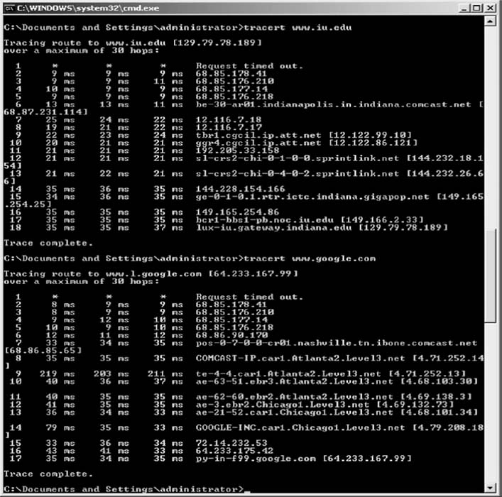
FIGURE 8.21 TraceRt without a VPN
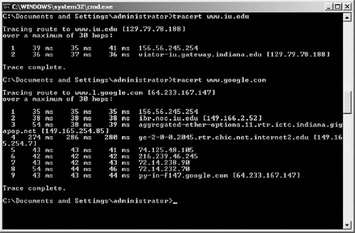
FIGURE 8.22 TraceRt with a VPN
1 It is called a cloud because what happens inside the common carrier's network is hidden from view. Network managers really don't care how the common carrier switches the circuit inside their network, just as long as the network is fast, accurate, and reliable.
2 If you multiply 24 circuits by 64 Kbps per circuit, you will get 1.536 Mbps, not 1.544 Mbps. This is because some of the 1.544-Mbps circuit capacity is used by the common carrier for control signals used to frame the data (i.e., mark the start and stop of packets).
3 Some common carriers and third-party vendors are now providing VPN services that use their own networks rather than the Internet. These networks offer an additional measure of security because in addition to flowing through the carrier's private network, they provide the same security benefits as VPN's on the public Internet. In the interest of simplicity, we will focus on Internet-based VPN services.