CHAPTER 6
WIRED AND WIRELESS LOCAL AREA NETWORKS

THE PRECEDING chapters provided a fundamental understanding of the five basic layers in a typical network. This chapter draws together these concepts to describe how wired and wireless LANs work. We first summarize the major components of LANs and then describe the two most commonly used LAN technologies: wired and wireless Ethernet. The chapter ends with a discussion of how to design LANs and how to improve LAN performance. In this chapter, we focus only on the basics of LANs; the next chapter describes how LANs and BNs are used together.
OBJECTIVES ![]()
- Be aware of the roles of LANs in organizations
- Understand the major components of LANs
- Understand wired Ethernet LANs
- Understand wireless Ethernet LANs
- Understand the best practice recommendations for LAN design
- Be familiar with how to improve LAN performance
CHAPTER OUTLINE ![]()
6.1.2 Dedicated-Server versus Peer-to-Peer LANs
6.2.3 Network Hubs, Switches, and Access Points
6.2.4 Network Operating Systems
6.4.3 Wireless Ethernet Frame Layout
6.4.4 Types of Wireless Ethernet
6.5 THE BEST PRACTICE LAN DESIGN
6.5.3 Designing for SOHO Environments
6.6.1 Improving Server Performance
6.6.2 Improving Circuit Capacity
6.7 IMPLICATIONS FOR MANAGEMENT
6.1 INTRODUCTION
Most large organizations have numerous wired and wireless LANs connected by backbone networks. These LANs also provide access to a variety of servers and the Internet. In this chapter, we discuss the fundamental components of a LAN, along with two technologies commonly used in LANs—traditional wired Ethernet (IEEE 802.3) that is commonly used to network desktop computers and wireless Ethernet (IEEE 802.11, commonly called Wi-Fi) that often is used to network laptop computers and mobile devices. There used to be many different types of LAN technologies, but gradually the world has changed so that Ethernet dominates.
6.1.1 Why Use a LAN?
There are two basic reasons for developing a LAN: information sharing and resource sharing. Information sharing refers to having users access the same data files, exchange information via email, or use the Internet. For example, a single purchase order database might be maintained so all users can access its contents over the LAN. (Many information-sharing applications were described in Chapter 2.) The main benefit of information sharing is improved decision making, which makes it generally more important than resource sharing.
Resource sharing refers to one computer sharing a hardware device (e.g., printer, an Internet connection) or software package with other computers on the network to save costs. For example, suppose we have 30 computers on a LAN, each of which needs access to a word processing package. One option is to purchase 30 copies of the software and install one on each computer. This would use disk space on each computer and require a significant amount of staff time to perform the installation and maintain the software, particularly if the package were updated regularly.
An alternative is to install the software on the network for all to use. This would eliminate the need to keep a copy on every computer and would free up disk space. It would also simplify software maintenance because any software upgrades would be installed once on the network server; staff members would no longer have to upgrade all computers.
In most cases, not all users would need to access the word processing package simultaneously. Therefore, rather than purchasing a license for each computer in the network, you could instead purchase 10 licenses, presuming that only 10 users would simultaneously use the software. Of course, the temptation is to purchase only one copy of the software and permit everyone to use it simultaneously. The cost savings would be significant, but this is illegal. Virtually all software licenses require one copy to be purchased for each simultaneous user. Most companies and all government agencies have policies forbidding the violation of software licenses, and many fire employees who knowingly violate them.
One approach to controlling the number of copies of a particular software package is to use LAN metering software that prohibits using more copies of a package than there are installed licenses. Many software packages now come in LAN versions that do this automatically, and a number of third-party packages are also available.
Nonetheless, the Software Publishers Association (SPA) in Washington, D.C., estimates that about 40 percent of all the software in the world is used illegally—an annual total of more than $40 billion. North America has the lowest rate of software piracy (28 percent). Although piracy has been on the decline, it still exceeds 75 percent in many parts of the world, with the exception of western Europe (43 percent), Australia (32 percent), New Zealand (35 percent), and Japan (41 percent). According to SPA, most software sold on eBay is pirated.
The SPA has recently undertaken an aggressive software audit program to check the number of illegal software copies on LANs. Whistleblowers receive rewards from SPA, and the violating organizations and employees are brought to court. SPA will work with companies that voluntarily submit to an audit, and it offers an audit kit that scrutinizes networks in search of software sold by SPA members (see www.spa.org).
6.1.2 Dedicated-Server versus Peer-to-Peer LANs
One common way to categorize LANs is by whether they have a dedicated server or whether they operate as a peer-to-peer LAN without a dedicated server. This chapter focuses primarily on dedicated-server LANs because they account for more than 99 percent of all installed LANs, although many of the issues are also common in peer-to-peer networks.
Dedicated Server Networks As the name suggests, a dedicated-server LAN has one or more computers that are permanently assigned as network servers. These servers enable users to share files and often are also used to share printers. A dedicated-server LAN can connect with almost any other network, can handle very large files and databases, and uses sophisticated LAN software. Moreover, high-end dedicated-server LANs can be easily interconnected to form enterprisewide networks or, in some cases, can replace a host mainframe computer. Generally speaking, the dedicated servers are powerful personal computers. Sometimes servers are organized into a large set of servers on one part of the network called a cluster or server farm. Server farms can range from tens to thousands of servers.
In a dedicated-server LAN, the server's usual operating system (e.g., Windows) is replaced by a network operating system (e.g., Linux, Windows Server). Special-purpose network communication software on each client computer is the link between the client computer's operating system and the network operating system on the server. This set of communication software (often called drivers) provides the data link layer and network layer protocols that allow data transmissions to take place. Three software components must work together and in conjunction with the network hardware to enable communications: the network operating system in the dedicated server, the network communication software on the client, and the application software that runs on the server and client computers.
A LAN can have many different types of dedicated servers, such as mail servers, database servers, and Web servers, as discussed in Chapter 10. Other common types are file servers and print servers.
File servers allow many users to share the same set of files on a common, shared disk drive. The hard disk volume can be of any size, limited only by the size of the disk storage itself. Files on the shared disk drive can be made freely available to all network users, shared only among authorized users, or restricted to only one user.
Print servers handle print requests on the LAN. By offloading the management of printing from the main LAN file server or database server, print servers help reduce the load on them and increase network efficiency. Print servers have traditionally been separate computers, but many vendors now sell “black boxes” that perform all the functions of a print server at much less than the cost of a stand-alone computer.
Peer-to-Peer Networks Peer-to-peer networks do not require a dedicated server. All computers run network software that enables them to function both as clients and as servers. Authorized users can connect to any computer in the LAN that permits access and use its hard drives and printer as though it were physically attached to their own computers. Peer-to-peer networks often are slower than dedicated server networks because if you access a computer that is also being used by its owner, it slows down both the owner and the network.
In general, peer-to-peer LANs have less capability, support a more limited number of computers, provide less sophisticated software, and can prove more difficult to manage than dedicated-server LANs. However, they are cheaper both in hardware and software. Peer-to-peer LANs are most appropriate for sharing resources in small LANs. We should note that peer-to-peer has become popular for application layer software file sharing on the Internet. This is conceptually similar to peer-to-peer LANs, but quite different in practice.
A Day in the Life: LAN Administrator
Most days start the same way. The LAN administrator arrives early in the morning before most people who use the LAN. The first hour is spent checking for problems. All the network hardware and servers in the server room receive routine diagnostics. All the logs for the previous day are examined to find problems. If problems are found (e.g., a crashed hard disk) the next few hours are spent fixing them. Next, the daily backups are done. This usually takes only a few minutes, but sometimes a problem occurs and it takes an hour.
The next step is to see if there are any other activities that need to be performed to maintain the network. This involves checking email for security alerts (e.g., Windows updates, antivirus updates). If critical updates are needed, they are done immediately. There are usually emails from several users that need to be contacted, either problems with the LAN, or requests for new hardware or software to be installed. These new activities are prioritized into the work queue.
And then the real work begins. Work activities include tasks such as planning for the next roll out of software upgrades. This involves investigating the new software offerings, identifying what hardware platforms are required to run them, and determining which users should receive the upgrades. It also means planning for and installing new servers or network hardware such as firewalls.
Of course, some days can be more exciting than others. When a new virus hits, everyone is involved in cleaning up the compromised computers and installing security patches on the other computers. Sometimes virus attacks can be fun when you see that your security settings work and beat the virus.
With thanks to Steve Bushert
6.2 LAN COMPONENTS
There are several components in a traditional LAN (Figure 6.1). The first two are the client computer and the server (but see the earlier section on peer-to-peer networks). Clients and servers have been discussed in Chapter 2, so they are not discussed further here. The other components are network interface cards (NICs), network circuits, hubs/switches/access points, and the network operating system.
6.2.1 Network Interface Cards
The network interface card (NIC) is used to connect the computer to the network cable in a wired network and is one part of the physical layer connection among the computers in the network. In a wireless network, the NIC is a radio transmitter that sends and receives messages on a specific radio frequency. Virtually all desktop computers have a wired NIC built in, while virtually all laptops have both a wired NIC and a wireless NIC. You can purchase a wireless NIC for a desktop computer (often as a USB device).
6.2.2 Network Circuits
Each computer must be physically connected by network circuits to the other computers in the network.
Wired LANs Most LANs are built with unshielded twisted-pair (UTP) cable, shielded twisted-pair (STP), or fiber-optic cable. (Common cable standards are discussed on the next page. We should add that these cable standards specify the minimum quality cable required; it is possible, for example, to use category 5 UTP wire for a 10Base-T Ethernet.)
Many LANs use UTP wire. Its low cost makes it very useful. STP is only used in special areas that produce electrical interference, such as factories near heavy machinery or hospitals near MRI scanners.

FIGURE 6.1 Local area network components
Fiber-optic cable is even thinner than UTP wire and therefore takes far less space when cabled throughout a building. It also is much lighter, weighing less than 10 pounds per 1,000 feet. Because of its high capacity, fiber-optic cabling is perfect for BNs, although it is beginning to be used in LANs.
Wireless LANs WLANs use radio transmissions to send data between the NIC and the AP. Most countries (but not all) permit WLANs to operate in two frequency ranges: the 2.4 GHz range and the 5 GHz range. These same frequency ranges can be used by cordless phones and baby monitors, which means that your WLAN and your cordless phone may interfere with each other. Under ideal conditions, the radio transmitters in the NICs and access points can transmit 100–150 meters (300–450 feet). In practice, the range is much shorter as walls absorb the radio waves. The other problem is that as the distance from the AP increases, the maximum speed drops, often very dramatically.
When we design a WLAN it is important to ensure that the APs don't interfere with each other. If all APs transmitted on the same frequency, the transmissions of one AP would interfere with another AP. Therefore, each AP is set to transmit on a different channel, very much like the different channels on your TV. Each channel uses a different part of the 2.4 GHz or 5 GHz frequency range so that there is no interference among the different channels. When a computer first starts using the WLAN, its NIC searches all available channels within the appropriate frequency range and then picks the channel that has the strongest signal.
6.1 COMMONLY USED NETWORK CABLE STANDARDS
TECHNICAL FOCUS
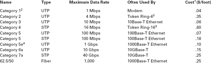
Notes
- These costs are approximate costs for cable only (no connectors). They often change but will give you a sense of the relative differences in costs among the different options.
- Category 1 is standard voice-grade twisted-pair wires but it can also be used to support low-speed analog data transmission.
- Token ring is an old local area network technology seldom used today.
- Category 5e is an improved version of category 5 that has better insulation and a center plastic pipe inside the cable to keep the individual wires in place and reduce noise from cross-talk, so that it is better suited to 1000Base-T.
6.2.3 Network Hubs, Switches, and Access Points
Network hubs and switches serve two purposes. First, they provide an easy way to connect network cables. A hub or a switch can be thought of as a junction box, permitting new computers to be connected to the network as easily as plugging a power cord into an electrical socket. Each connection point where a cable can be plugged in is called a port. Each port has a unique number. Switches can be designed for use in small office, home office (SOHO) environments (see Figure 6.2a) or for large enterprise environments (see Figure 6.2b).
Simple hubs and switches are commonly available in 4-, 8-, 16-, and 24-port sizes, meaning that they provide anywhere between 4 and 24 ports into which network cables can be plugged. When no cables are plugged in, the signal bypasses the unused port. When a cable is plugged into a port, the signal travels down the cable as though it were directly connected to the hub or switch. Some switches also enable different types of cables to be connected and perform the necessary conversions (e.g., twisted-pair cable to coaxial cable, coaxial cable to fiber-optic cable).
Second, hubs and switches act as repeaters. Signals can travel only so far in a network cable before they attenuate and can no longer be recognized. (Attenuation was discussed in Chapter 4.) All LAN cables are rated for the maximum distance they can be used (typically 100 meters for twisted-pair cable, and 400 meters to several kilometers for fiber-optic cable).
A wireless access point (AP) is a radio transceiver that plays the same role as a hub or switch in wired Ethernet LANs. It enables the computers near it to communicate with each other and it also connects them into wired LANs, typically using 100Base-T. All NICs in the WLAN transmit their frames to the AP and then the AP retransmits the frames over the wireless network or over the wired network to their destination. Therefore, if a frame has to be transmitted from one wireless computer to another, it is transmitted twice, once from the sender to the AP and then from the AP to the destination. At first glance this may seem a bit strange because it doubles the number of transmissions in the WLAN. However, very few frames are ever sent from client computer to client computer in a WLAN. Most frames are exchanged between client computers and a server of some kind. Because AP acts as ‘gatekeeper’ this can potentially slow down the speed of communication. This is especially true if a server would be placed on a WLAN. Therefore, a server should never be placed on a WLAN because client computers cannot reach it directly but have to communicate with it via the AP. Even if they are intended to serve clients on a WLAN, they should always be placed on the wired portion of the LAN.
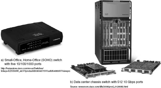
FIGURE 6.2 Lan switches
Source: Courtesy Cisco Systems, Inc. Unauthorized use not permitted.
6.1 CABLE PROBLEMS AT THE UNIVERSITY OF GEORGIA
MANAGEMENT FOCUS
Like many organizations, the Terry College of Business at the University of Georgia is headquartered in a building built before the computer age. When local area network cabling was first installed in the early 1980s, no one foresaw the rapid expansion that was to come. Cables and hubs were installed piecemeal to support the needs of the handful of early users.
The network eventually grew far beyond the number of users it was designed to support. The network cabling gradually became a complex, confusing, and inefficient mess. There was no logical pattern for the cables, and there was no network cable plan. Worse still, no one knew where all the cables and hubs were physically located. Before a new user was added, a network technician had to open up a ceiling and crawl around to find a hub. Hopefully, the hub had an unused port to connect the new user, or else the technician would have to find another hub with an empty port.
To complicate matters even more, asbestos was discovered. Now network technicians could not open the ceiling and work on the cable unless asbestos precautions were taken. This meant calling in the university's asbestos team and sealing off nearby offices. Installing a new user to the network (or fixing a network cable problem) now took two days and cost $2,000.
The solution was obvious. The university spent $400,000 to install new category 5 twisted-pair cable to every office and to install a new high-speed fiber-optic backbone network between network segments.
Figure 6.3a shows an AP for use in SOHO (small office, home office) environments. This AP is wired into the regular Ethernet LAN and has a separate power supply that is plugged into a normal electrical outlet. Figure 6.3b shows an AP for use in large enterprises. It is also wired into the regular Ethernet LAN, but it uses power over Ethernet (POE) so it needs no external power; the power is provided from a POE switch over the unused wires in a category 5/5e cable. POE APs are more expensive, but can be located anywhere you can run Cat 5/5e cable, even if there are no power outlets nearby.
Most WLANs are installed using APs that have omnidirectional antennas, which means that the antenna transmits in all directions simultaneously. Some antennas are built into the AP itself, while others stick up above it. One common omnidirectional antenna is the dipole antenna shown in Figure 6.3a; others are built into the AP box, as is Figure 6.3b.

FIGURE 6.3 Wireless access points
The other type of antenna that can be used on APs is the directional antenna, which, as the name suggests, projects a signal only in one direction. Because the signal is concentrated in a narrower, focused area, the signal is stronger and therefore will carry farther than the signal from an AP using an omnidirectional antenna. Directional antennas are most often used on the inside of an exterior wall of a building, pointing to the inside of the building. This keeps the signal inside the building (to reduce security issues) and also has the benefit of increasing the range of the AP.
Many wireless routers are sold for use in SOHO environments. The wireless routers are both a wireless access point and a router, and many also contain a 100Base-T switch. It is important not to use the term wireless router when you mean a wireless access point.
6.2 MANAGING NETWORK CABLING
MANAGEMENT FOCUS
You must consider a number of items when installing cables or when performing cable maintenance. You should:
- Perform a physical inventory of any existing cabling systems and document those findings in the network cable plan.
- Properly maintain the network cable plan. Always update cable documentation immediately on installing or removing a cable or hub. Insist that any cabling contractor provide “as-built” plans that document where the cabling was actually placed, in case of minor differences from the construction plan.
- Establish a long-term plan for the evolution of the current cabling system to whatever cabling system will be in place in the future.
- Obtain a copy of the local city fire codes and follow them. For example, cables used in airways without conduit need to be plenum-certified (i.e., covered with a fire-retardant jacket).
- Conceal all cables as much as possible to protect them from damage and for security reasons.
- Properly number and mark both ends of all cable installations as you install them. If a contractor installs cabling, always make a complete inspection to ensure that all cables are labeled.
6.2.4 Network Operating Systems
The network operating system (NOS) is the software that controls the network. Every NOS provides two sets of software: one that runs on the network server(s) and one that runs on the network client(s). The server version of the NOS provides the software that performs the functions associated with the data link, network, and application layers and usually the computer's own operating system. The client version of the NOS provides the software that performs the functions associated with the data link and the network layers and must interact with the application software and the computer's own operating system. Most NOSs provide different versions of their client software that run on different types of computers, so that Windows computers, for example, can function on the same network as Apples. In most cases (e.g., Windows, Linux), the client NOS software is included with the operating system itself.
NOS Server Software The NOS server software enables the file server, print server, or database server to operate. In addition to handling all the required network functions, it acts as the application software by executing the requests sent to it by the clients (e.g., copying a file from its hard disk and transferring it to the client, printing a file on the printer, executing a database request, and sending the result to the client). NOS server software replaces the normal operating system on the server. By replacing the existing operating system, it provides better performance and faster response time because a NOS is optimized for its limited range of operations. The most commonly used NOS are Widows Server and Linux.
NOS Client Software The NOS software running at the client computers provides the data link layer and network layer. Most operating systems today are designed with networking in mind. For example, Windows provides built-in software that will enable it to act as a client computer with a Windows Server.
One of the most important functions of a NOS is a directory service. Directory services provide information about resources on the network that are available to the users, such as shared printers, shared file servers, and application software. A common example of directory services is Microsoft's Active Directory Service (ADS).
Active Directory Service works in much the same manner as TCP/IP's DNS service, and in fact ADS servers, called domain controllers, can also act as DNS servers. Network resources are typically organized into a hierarchical tree. Each branch on the tree contains a domain, a group of related resources. For example, at a university, one domain might be the resources available within the business school, and another domain might be the resources in the computer science school, while another might be in the medical school. Domains can contain other domains, and in fact the hierarchical tree of domains within one organization can be linked to trees in other organizations to create a forest of shared network resources.
Within each domain, there is a server (the domain controller) that is responsible for resolving address information (much like a DNS server resolves address information on the Internet). The domain controller is also responsible for managing authorization information (e.g., who is permitted to use each resource) and making sure that resources are available only to authorized users. Domain controllers in the same tree (or forest) can share information among themselves, so that a domain controller in one part of the tree (or forest) can be configured to permit access to resources to any user that has been approved by another domain controller in a different part of the tree (or forest).
6.2 STORAGE AREA NETWORKS AND NETWORK-ATTACHED STORAGE
TECHNICAL FOCUS
New ideas and new terms emerge rapidly in data communications and networking. In recent years, a variant on the local area network (LAN) has emerged. A storage area network (SAN) is a LAN devoted solely to data storage. When the amount of data to be stored exceeds the practical limits of servers, the SAN plays a critical role. The SAN has a set of high-speed storage devices and servers that are networked together using a very high speed network (often using a technology called fiber channel that runs over a series of multi-gigabit point-to-point fiber-optic circuits). Servers are connected into the normal LAN and to the SAN, which is usually reserved for servers. When data are needed, clients send the request to a server on the LAN, which obtains the information from the devices on the SAN and then returns it to the client.
The devices on the SAN may be a large set of database servers or a set of network-attached disk arrays. In other cases, the devices may be network-attached storage (NAS) devices. A NAS is not a general-purpose computer like a server that runs a server operating system (e.g., Windows, Linux); it has a small processor and a large amount of disk storage and is designed solely to respond to requests for files and data. NAS can also be attached to LANs where they function as a fast file server.
If you log-in to a Microsoft server or domain controller that provides ADS, you can see all network resources that you are authorized to use. When a client computer wishes to view available resources or access them, it sends a message using an industry standard directory protocol called lightweight directory services (LDAP) to the ADS domain controller. The ADS domain controller resolves the textual name in the LDAP request to a network address and—if the user is authorized to access the resource—provides contact information for the resource.
Network Profiles A network profile specifies what resources on each server are available on the network for use by other computers and which devices or people are allowed what access to the network. The network profile is normally configured when the network is established and remains in place until someone makes a change. In a LAN, the server hard disk may have various resources that can or cannot be accessed by a specific network user (e.g., data files, printers). Furthermore, a password may be required to grant network access to the resources.
If a device such as a hard disk on one of the network's computers is not included on the network profile, it cannot be used by another computer on the network. For example, if you have a hard disk (C) on your computer and your computer is connected to this LAN but the hard disk is not included on the network profile assignment list, then no other computer can access that hard disk.
In addition to profiling disks and printers, there must be a user profile for each person who uses the LAN, to add some security. Each device and each user is assigned various access codes, and only those users who log in with the correct code can use a specific device. Most LANs keep audit files to track who uses which resource. Security is discussed in Chapter 9.
6.3 WIRED ETHERNET
Almost all LANs installed today use some form of Ethernet. Ethernet was originally developed by DEC, Xerox, and Intel but has since become a standard formalized by the IEEE as IEEE 802.3. 1 The IEEE 802.3 version of Ethernet is slightly different from the original version but the differences are minor. Likewise, another version of Ethernet has also been developed that differs slightly from the 802.3 standard. In this section, we describe traditional Ethernet which is sometimes called shared Ethernet.
Ethernet is a layer 2 protocol, which means it operates at the data link layer. Every Ethernet LAN needs hardware at layer 1, the physical layer, that matches the requirements of the Ethernet software at layer 2. Ethernet is compatible with a variety of layer 3 protocols but is commonly used with TCP/IP.
6.3.1 Topology
Topology is the basic geometric layout of the network—the way in which the computers on the network are interconnected. It is important to distinguish between a logical topology and a physical topology. A logical topology is how the network works conceptually, much like a logical data flow diagram (DFD) or logical entity relation diagram (ERD) in systems analysis and design or database design. A physical topology is how the network is physically installed, much like a physical DFD or physical ERD.
Hub-Based Ethernet When we use hubs, Ethernet's logical topology is a bus topology. All computers are connected to one half-duplex circuit running the length of the network that is called the bus. The top part of Figure 6.4 shows Ethernet's logical topology. All frames from any computer flow onto the central cable (or bus) and through it to all computers on the LAN. Every computer on the bus receives all frames sent on the bus, even those intended for other computers. Before processing incoming frames, the Ethernet software on each computer checks the data link layer address and processes only those frames addressed to that computer.
The bottom part of Figure 6.4 shows the physical topology of an Ethernet LAN when a hub is used. From the outside, an Ethernet LAN appears to be a star topology, because all cables connect to the central hub. Nonetheless, it is logically a bus.
With hubs, all computers share the same multipoint circuit and must take turns using it. When one computer transmits, all the other computers must wait, which is very inefficient.
Switch-Based Ethernet When we use switches, Ethernet's topology is a logical star and a physical star (Figure 6.5). From the outside, the switch looks almost identical to a hub, but inside, it is very different. A switch is an intelligent device with a small computer built-in that is designed to manage a set of separate point-to-point circuits. That means that each circuit connected to a switch is not shared with any other devices; only the switch and the attached computer use it. The physical topology looks essentially the same as Ethernet's physical topology: a star. On the inside, the logical topology is a set of separate point-to-point circuits, also a star. Many switches support full duplex circuits, meaning that each circuit can simultaneously send and receive.
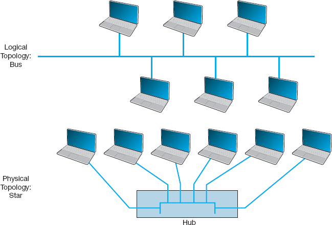
FIGURE 6.4 Ethernet topology using hubs
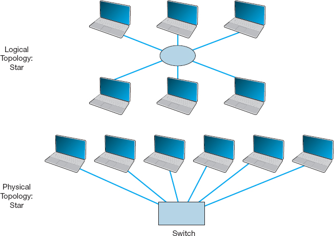
FIGURE 6.5 Ethernet topology using switches
When a switch receives a frame from a computer, it looks at the address on the frame and retransmits the frame only on the circuit connected to that computer, not to all circuits as a hub would. Therefore, no computer needs to wait because another computer is transmitting; every computer can transmit at the same time, resulting in much faster performance. Today, no one buys a hub unless she or he can't afford a switch.
So how does a switch know which circuit is connected to what computer? The switch uses a forwarding table that is very similar to the routing tables discussed in Chapter 5. The table lists the Ethernet address of the computer connected to each port on the switch. When the switch receives a frame, it compares the destination address on the frame to the addresses in its forwarding table to find the port number on which it needs to transmit the frame. Because the switch uses the Ethernet address to decide which port to use and because Ethernet is a data link layer or layer-2 protocol, this type of switch is called a layer-2 switch.
When switches are first turned on, their forwarding tables are empty; they do not know what Ethernet address is attached to what port. Switches learn addresses to build the forwarding table. When a switch receives a frame, it reads the frame's data link layer source address and compares this address to its forwarding table. If the address is not in the forwarding table, the switch adds it, along with the port on which the frame was received.
If a switch receives a frame with a destination address that is not in the forwarding table, the switch must still send the frame to the correct destination. In this case, it must retransmit the frame to all ports, except the one on which the frame was received. The attached computers, being Ethernet and assuming they are attached to a hub, will simply ignore all frames not addressed to them. The one computer for whom the frame is addressed will recognize its address and will process the frame, which includes sending an ACK or a NAK back to the sender. When the switch receives the ACK or NAK, it will add this computer's address and the port number on which the ACK or NAK was received to its forwarding table and then send the ACK or NAK on its way.
So, for the first few minutes until the forwarding table is complete, the switch acts like a hub. But as its forwarding table becomes more complete, it begins to act more and more like a switch. In a busy network, it takes only a few minutes for the switch to learn most addresses and match them to port numbers. To make a switch work faster, the most active connections are placed on the top of the forwarding table. If a computer is not communicating for more than 300 seconds, its entry is usually removed from the forwarding table.
There are three modes in which switches can operate. The first is cut-through switching. With cut-through switching, the switch begins to transmit the incoming packet on the proper outgoing circuit as soon as it has read the destination address in the frame. In other words, the switch begins transmitting before it has received the entire frame. The advantage of this is low latency (the time it takes a device from receiving a frame to transmitting it) and results in a very fast network. The disadvantage is that the switch begins transmitting before it has read and processed the frame check sequence at the end of the frame; the frame may contain an error, but the switch will not notice until after almost all of the frame has been transmitted. Cut-through switching can only be used when the incoming data circuit has the same data rate as the outgoing circuit.
With the second switching mode, called store and forward switching, the switch does not begin transmitting the outgoing frame until it has received the entire incoming frame and has checked to make sure it contains no errors. Only after the switch is sure there are no errors does the switch begin transmitting the frame on the outgoing circuit. If errors are found, the switch simply discards the frame. This mode prevents invalid frame from consuming network capacity, but provides higher latency and thus results in a slower network (unless many frames contain errors). Store and forward switching can be used regardless of whether the incoming data circuit has the same data rate as the outgoing circuit because the entire frame must be stored in the switch before it is forwarded on its way.
The final mode, called fragment-free switching, lies between the extremes of cut-through switching and store and forward switching. With fragment-free switching, the first 64 bytes of the frame are read and stored. The switch examines the first 64 bytes (which contain all the header information for the frame) and if all the header data appears correct, the switch presumes that the rest of the frame is error free and begins transmitting. Fragment-free switching is a compromise between cut through and store and forward switching because it has higher latency and better error control than cut through switching, but lower latency and worse error control than store and forward switching. Most switches today use cut through or fragment-free switching.
6.3.2 Media Access Control
When several computers share the same communication circuit, it is important to control their access to the media. If two computers on the same circuit transmit at the same time, their transmissions will become garbled. These collisions must be prevented, or if they do occur, there must be a way to recover from them. This is called media access control.
Ethernet uses a contention-based media access control technique called Carrier Sense Multiple Access with Collision Detection (CSMA/CD). CSMA/CD, like all contention-based techniques, is very simple in concept: wait until the circuit is free and then transmit. Computers wait until no other devices are transmitting, then transmit their frames. As an analogy, suppose you are talking with a small group of friends (four or five people). As the discussion progresses, each person tries to grab the floor when the previous speaker finishes. Usually, the other members of the group yield to the first person who jumps right after the previous speaker.
Ethernet's CSMA/CD protocol can be termed “ordered chaos.” As long as no other computer attempts to transmit at the same time, everything is fine. However, it is possible that two computers located some distance from one another can both listen to the circuit, find it empty, and begin simultaneously. This simultaneous transmission is called a collision. The two frames collide and destroy each other.
The solution to this is to listen while transmitting, better known as collision detection (CD). If the NIC detects any signal other than its own, it presumes that a collision has occurred and sends a jamming signal. All computers stop transmitting and wait for the circuit to become free before trying to retransmit. The problem is that the computers that caused the collision could attempt to retransmit at the same time. To prevent this, each computer waits a random amount of time after the colliding frame disappears before attempting to retransmit. Chances are both computers will choose a different random amount of time and one will begin to transmit before the other, thus preventing a second collision. However, if another collision occurs, the computers wait a random amount of time before trying again. This does not eliminate collisions completely, but it reduces them to manageable proportions.
6.3.3 Types of Ethernet
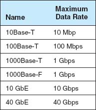
Figure 6.6 summarizes the many different types of Ethernet in use today. It was the 10Base-T standard that revolutionized Ethernet and made it the most popular type of LAN in the world. 100Base-T is the most common form of Ethernet today.
Other types of Ethernet include: 1000Base-T and 1000Base-F (which run at 1 Gbps and are sometimes called 1 GbE), 10 GbE (which runs at 10 Gbps), and 40 GbE (which runs at 40 Gbps). They can use Ethernet's traditional half-duplex approach, but most are configured to use full duplex. Each is also designed to run over fiber-optic cables, but some may also use traditional twisted-pair cables (e.g., Cat 5, Cat 5e). For example, two common versions of 1000Base-F are 1000Base-LX and 1000Base-SX, which both use fiber-optic cable, running up to 440 meters and 260 meters, respectively; 1000Base-T, which runs on four pairs of category 5 twisted-pair cable, but only up to 100 meters2; and 1000Base-CX, which runs up to 24 meters on one category 5 cable. Similar versions of 10 GbE and 40 GbE that use different media are also available.
Some organizations use 10/100/1000 Ethernet, which is a hybrid that can run at any of these three speeds. 10/100/1000 NICs and switches detect the signal transmitted by the computer or device on the other end of the cable and and will use 10 Mbps, 100 Mbps, or 1 Gbps depending on which the other device uses.
6.3 MOVING TO GIGABIT ETHERNET
MANAGEMENT FOCUS
Kotak Mahindra Group, one of India's leading financial services provider, offers comprehensive financial solutions such as commercial banking, stock brokering, mutual funds, life insurance, and investment banking. They employ 20,000 people at over 1300 branches in India and around the world.
Because of the high network traffic in their main data center location, Kotak installed gigabit Ethernet switches in their core network. The switches provide 512 ports of 10GbE, with the ability to upgrade to 40 Gbps and 100 Gbps. The switches have an internal switching capacity of 15 Tbps (15 trillion bits per second) so there is room for growth.
_________
SOURCE: “Kotak Group Builds State-of-the-Art Data Center on Cisco Nexus 7000 Switch,” Cisco Customer Case Study, Cisco Systems, 2009.
6.4 WIRELESS ETHERNET
Wireless Ethernet ( commonly called Wi-Fi) is the commercial name for a set of standards developed by the IEEE 802.11 standards group. A group of vendors selling 802.11 equipment trademarked the name Wi-Fi to refer to 802.11 because they believe that consumers are more likely to buy equipment with a catchier name than 802.11. Wi-Fi is intended to evoke memories of Hi-Fi, as the original stereo music systems in the 1960s were called.
The 802.11 family of technologies is much like the Ethernet family. They reuse many of the Ethernet 802.3 components and are designed to connect easily into Ethernet LANs. For these reasons, IEEE 802.11 is often called wireless Ethernet. Just as there are several different types of Ethernet (e.g., 10Base-T, 100Base-T, 1000Base-T), there are several different types of 802.11.
6.4.1 Topology
The logical and physical topologies of Wi-Fi are the same as those of hub-based Ethernet: a physical star and a logical bus. There is a central AP to which all computers direct their transmissions (star), and the radio frequencies are shared (bus) so that all computers must take turns transmitting.
6.4.2 Media Access Control
Media access control in Wi-Fi is Carrier Sense Multiple Access with Collision Avoidance (CSMA/CA), which is similar to the contention-based CSMA/CD approach used by Ethernet. With CSMA/CA, computers listen before they transmit and if no one else is transmitting, they proceed with transmission. Detecting collisions is more difficult in radio transmission than in transmission over wired networks, so Wi-Fi attempts to avoid collisions to a greater extent than traditional Ethernet. CSMA/CA has two media access control approaches. However, before a computer can transmit in a WLAN is must first establish an association with a specific AP, so that the AP will accept its transmissions.
Associating with an AP Searching for an available AP is called scanning and NIC can engage in either active or passive scanning. During active scanning, a NIC transmits a special frame called probe frame on all active channels on its frequency range. When an AP receives a probe frame, it responds with a probe response that contains all the necessary information for a NIC to associate with it. A NIC can receive several probe responses from different APs. It is up to the NIC to choose with which AP to associate with. This usually depends on the speed rather than distance from an access point. Once a NIC associates with an access point they start exchanging packets over the channel that is specified by the access point.
During passive scanning, the NIC listens on all channels for a special frame called beacon frame that is sent out by an access point. The beacon frame contains all the necessary information for a NIC to associate with it. Once a NIC detects this beacon frame it can decide to associate with it and start communication on the frequency channel set by the access point.
Distributed Coordination Function The first media access control method is the distributed coordination function (DCF) (also called physical carrier sense method because it relies on the ability of computers to physically listen before they transmit). With DCF, each frame in CSMA/CA is sent using stop-and-wait ARQ. After the sender transmits one frame, it immediately stops and waits for an ACK from the receiver before attempting to send another frame. When the receiver of a frame detects the end of the frame in a transmission, it waits a fraction of a second to make sure the sender has really stopped transmitting, and then immediately transmits an ACK (or a NAK). The original sender can then send another frame, stop and wait for an ACK, and so on. While the sender and receiver are exchanging frames and ACKs, other computers may also want to transmit. So when the sender ends its transmission, you might ask why doesn't some other computer begin transmitting before the receiver can transmit an ACK? The answer is that the physical carrier sense method is designed so that the time the receiver waits after the frame transmission ends before sending an ACK is significantly less time than the time a computer must listen to determine that no one else is transmitting before initiating a new transmission. Thus, the time interval between a frame and the matching ACK is so short that no other computer has the opportunity to begin transmitting.
Point Coordination Function The second media access control technique is called the point coordination function (PCF) (also called the virtual carrier sense method). Not all manufacturers have implemented PCF in their APs. DCF works well in traditional Ethernet because every computer on the shared circuit receives every transmission on the shared circuit. However, in a wireless environment, this is not always true. A computer at the extreme edge of the range limit from the AP on one side may not receive transmissions from a computer on the extreme opposite edge of the AP's range limit. In Figure 6.1, all computers may be within the range of the AP, but may not be within the range of each other. In this case, if one computer transmits, the other computer on the opposite edge may not sense the other transmission and transmit at the same time causing a collision at the AP. This is called the hidden node problem because the computers at the opposite edges of the WLAN are hidden from each other.
When the hidden node problem exists, the AP is the only device guaranteed to be able to communicate with all computers on the WLAN. Therefore, the AP must manage the shared circuit using a controlled-access technique, not the contention-based approach of traditional Ethernet. With this approach, any computer wishing to transmit first sends a request to transmit (RTS) to the AP, which may or may not be heard by all computers. The RTS requests permission to transmit and to reserve the circuit for the sole use of the requesting computer for a specified time period. If no other computer is transmitting, the AP responds with a clear to transmit (CTS), specifying the amount of time for which the circuit is reserved for the requesting computer. All computers hear the CTS and remain silent for the specified time period. The virtual carrier sense method is optional. It can always be used, never used, or used just for frames exceeding a certain size, as set by the WLAN manager.
Controlled-access methods provide poorer performance in low-traffic networks because computers must wait for permission before transmitting rather than just waiting for an unused time period. However, controlled-access techniques work better in high-traffic WLANs because without controlled access there are many collisions. Think of a large class discussion in which the instructor selects who will speak (controlled access) versus one in which any student can shout out a comment at any time.
6.4.3 Wireless Ethernet Frame Layout
An 801.11 data frame is illustrated on Figure 6.7. We notice two major differences when we compare the 802.11 frame to the 802.3 frame used in wired Ethernet (see Chapter 4). First, the wireless Ethernet frame has four address fields rather than two like the wired Ethernet. These four address fields are source address, transmitter address, receiver address, and destination address. The source and destination address have the same meaning as in wired Ethernet. However, because every NIC has to communicate via an access point (it cannot directly communication with another NIC), there is a need to add the address of the access point and also any other device that might be needed to transmit the frame. To do this, the transmitter and received address fields are used.
Second, there is new field called Sequence Control that indicates how a large frame is fragmented—split into smaller pieces. Recall that in wired networks this is done by the Transport Layer, not the Data Link Layer. Moving the segmentation to the Data Link Layer for wireless makes the transmission transparent to the higher layers. The price, however, is less efficiency because of the size of the frame and thus also higher error rate.
6.4.4 Types of Wireless Ethernet
Wi-Fi is one of the fastest changing areas in networking. There are four types of Wi-Fi but one, the latest version (802.11n) is dominant today. The other three versions are obsolete, but may still be in use in some companies.

FIGURE 6.7 A Wireless Ethernet Frame
802.11a IEEE 802.11a is an obsolete, legacy technology, and no new products are being developed. Under perfect conditions, it provides eight channels of 54 Mbps each with a maximum range of 50 meters or 150 feet. Speeds of 20 Mbps at 50 foot ranges are more common in the face of interference such as drywall or brick walls.
802.11b IEEE 802.11b is another obsolete, legacy technology. Under perfect conditions, it provides three channels of 11 Mbps each with a maximum range of 150 meters or 450 feet, although in practice both the speed and range are lower.
802.11g IEEE 802.11g is another obsolete, legacy technology, but many organizations still use it. Under perfect conditions, it provides three channels of 54 Mbps each with a maximum range of 150 meters or 450 feet, although in practice both the speed and range are lower.
802.11n IEEE 802.11n is the latest version of Wi-Fi that most firms use (or are in the process of installing). Under perfect conditions, it provides three channels of about 200 Mbps each with a maximum range of 150 meters or 450 feet, although in practice both the speed and range are lower. It is also possible to configure APs to use different frequency ranges to provide fewer channels that run at higher speeds up to 600 Mbps each.
IEEE 802.11n is backward compatible with 802.11b and 802.11g, so that laptops that use these older versions can use an 802.11n access point. However, this backward compatibility comes with a price. These old laptops become confused when 802.11n devices operate at high speeds near them, so when an 802.11n AP detects the presence of an 802.11b or 802.11g device, it prohibits newer laptops that use 802.11n devices from operating at high speeds. Thus one old laptop will slow down all the other laptops around it.
6.4.5 Security
Security is important to all networks and types of technology, but it is especially important for wireless networks. With a WLAN, anyone walking or driving within the range of an AP (even outside the offices) can begin to use the network.
Finding WLANs is quite simple. You just walk or drive around different office buildings with your WLAN-equipped client computer and see if it picks up a signal. There are also many special-purpose software tools available on the Internet that will enable you to learn more about the WLANs you discover, with the intent of helping you to break into them. This type of wireless reconnaissance is often called wardriving (see www.wardriving.com). Warchalking refers to the practice of writing symbols in chalk on sidewalks and walls to indicate the presence of an unsecured WLAN (see www.warchalking.org).
WEP One wireless security technique is Wired Equivalent Privacy (WEP). With WEP, the AP requires the user to have a key in order to communicate with it. All data sent to and from the AP is encrypted so that it can only be understood by computers or devices that have the key (encryption is discussed in more detail in Chapter 10). If a computer does not have the correct WEP key, it cannot understand any messages transmitted by the access point and the access point will not accept any data that is not encrypted with the correct key.
The key can be manually typed into the client computer and into the AP. Although this is not a major problem in a small WLAN, it does become challenging for large WLANs. Imagine the management time required when a WEP key needs to be changed in an organization with dozens of APs and hundreds of client computers (or hundreds of APs and thousands of computers).
With Extensible Authentication Protocol (EAP), the WEP keys are produced dynamically, much like the way in which a DHCP server is used to dynamically produce IP addresses. When an AP using EAP first discovers a new client computer, it requires the user to login before it will communicate with the client computer. The user ID and password supplied by the user are transmitted to a login server, and if the server determines that they are valid the server generates a WEP key that will be used by the AP and client computer to communicate for this session. Once the client logs out or leaves the WLAN, the WEP is discarded and the client must login again and receive a new WEP key.
Wired Equivalent Privacy has a number of serious weaknesses, and most experts agree that a determined hacker can break into a WLAN that uses only WEP security. A good way to think about WEP is that it is like locking your doors when you leave: It won't keep out a professional criminal but it will protect against a casual thief.
WPA Wi-Fi Protected Access (WPA) is a newer, more secure type of security. WPA works in ways similar to WEP and EAP: every frame is encrypted using a key, and the key can be fixed in the AP like WEP or can be assigned dynamically as users login like EAP. The difference is that the WPA key is longer than the WEP key and thus is harder to break. More importantly, the key is changed for every frame that is transmitted to the client. Each time a frame is transmitted, the key is changed.
802.11i 802.11i (also called WPA2) is the newest, most secure type of WLAN security. It uses EAP to obtain a master key—in other words, the user logs in to a login server to obtain the master key. Armed with this master key, the user's computer and the AP negotiate a new key that will be used for this session until the users leaves the WLAN. 802.11i uses the Advanced Encryption Standard (AES) discussed in Chapter 10 as its encryption method.
MAC Address Filtering With MAC address filtering, the AP permits the owner to provide a list of MAC addresses (i.e., layer-2 addresses). The AP only processes frames sent by computers whose MAC address is in the address list; if a computer with a MAC address not in the list sends a frame, the AP ignores it. Unfortunately, this provides no security against a determined hacker. There is software available that will change the MAC address on a wireless NIC, so a determined hacker could use a packet sniffer (e.g., Wireshark) to discover a valid MAC address and then use the software to change his MAC address to one the AP would accept. MAC address filtering is like WEP; it will protect against a casual thief, but not a professional.
MANAGEMENT FOCUS
If you connect into someone else's Wi-Fi network and start using their Internet connection are you:
- Guilty of stealing from the owner because you haven't paid them
- Guilty of stealing from the ISP because you haven't paid them
- Committing an unethical but not illegal act
- Really frugal, and not unethical
- All of the above
According to the St Petersburg, Florida, police department, the answer is a. They arrested a man named Benjamin Smith for “willfully, knowingly, and without authorization” accessing the network of a homeowner while sitting in a car parked on the street.
According to Verizon and most ISPs, which explicitly prohibit sharing, the answer is b. “It's obviously not good for Verizon to have its services given away for free, just as a cable company won't want someone funneling their cable connection next door,” said a Verizon spokeswoman.
According to Miss Manners, the answer is c. It's not nice to use other people's stuff without asking their permission.
According to Jennifer Granick, executive director of the Center for Internet and Society at Stanford Law School, the answer is d. “Such use [i.e., sharing] might be allowed or even encouraged [by the owner].” Unless the owner states you can't enter their network, how do you know you're not invited?
As Lee Tien, a senior staff attorney at the Electronic Frontier Foundation says “Right now, we don't have a way of saying ‘Even though my wireless signal is open, I'm saying you can't use it.”’ Until we do, the answer is e. So, tread carefully. Don't leave your WLAN unsecured or you may be legally inviting others to use it as well as your Internet connection. Likewise, don't intentionally enter someone else's WLAN and use their Internet connection or you might end up like Benjamin Smith—spending the night in jail.
__________
SOURCE: John Cox, “Mooching Wi-Fi,” Network World, August 8, 2005, pp. 1, 49.
6.5 THE BEST PRACTICE LAN DESIGN
The past few years have seen major changes in LAN technologies (e.g., gigabit Ethernet, high-speed wireless Ethernet). As technologies have changed and costs have dropped, so too has our understanding of the best practice design for LANs.
One of the key questions facing network designers is the relationship between Wi-Fi and wired Ethernet. The data rates for Wi-Fi have increased substantially with the introduction of 802.11n, so they are similar to the data rates offered by 100Base-T wired Ethernet. The key difference is that 100Base-T wired Ethernet using switches provides 100 Mbps to each user, whereas Wi-Fi shares its available capacity among every user on the same AP, so as more users connect to the APs, the network gets slower and slower.
Wi-Fi is considerably cheaper than wired Ethernet because the largest cost of LANs is not the equipment, but in paying someone to install the cables. The cost to install a cable in an existing building is typically between $150 and $400 per cable, depending on whether the cable will have to be run through drywall, brick, ceilings, and so on. Installing cable in a new building during construction is cheaper, typically $50 to $100 per cable.
6.5 WILL WI-FI REPLACE WIRED LANS?
MANAGEMENT FOCUS
As KPMG, one of the largest consulting firms in the world, began to build a new 2800-person headquarters near Amsterdam, KPMG's IT group realized that their traditional wired network approach would have required 18,000 cable runs, 55 chassis switches, and 260 LAN switches. The up-front cost was expected to exceed $6 million and the recurring operating costs would run into the millions annually as well.
KPMG began to wonder if there was a better way. Could they build an entirely wireless network that would meet their needs?
After careful analysis, KPMG decided they were not ready to go completely wireless. However, they decided to shift a substantial portion of their traditionally wired users to wireless. They cut their wired network by half and installed over 500 802.11n access points throughout the new facility to provide complete coverage for data and voice. The new network design cut the initial cost by $2 million and reduced annual operating costs by $750,000 per year.
The new design also delivered substantial green benefits. Access Points use about 5% of the electricity that 48-port switches require for power and cooling. By eliminating half the switches, the new design eliminated over 350 metric tons of carbon dioxide emissions each year.
___________
SOURCE: “KPMG Netherlands Counts on Aruba for Network Rightsizing,” Enterprise Case Study, Aruba Networks, 2009.
Most organizations today are still installing traditional wired Ethernet for desktop users and using Wi-Fi as overlay networks. They build the usual switched Ethernet networks as the primary LAN, but they also install Wi-Fi for laptops. Some organizations have begun experimenting with Wi-Fi by moving groups of users off the wired networks onto Wi-Fi as their primary network to see whether Wi-Fi is suitable as a primary network.
Today, we still believe the best practice is to use wired Ethernet for the primary LAN, with Wi-Fi as an overlay network. However, this may change. Stay tuned.
6.5.1 Wired Ethernet
Many organizations today install switched 100Base-T over category 5e wiring for their wired LANs. It is relatively low cost and fast. Another good alternative is 10/100/1000 over cat 5e wires.
In the early days of LANs, it was common practice to install network cable wherever it was convenient. Little long-term planning was done. The exact placement of the cables was often not documented, making future expansion more difficult—you had to find the cable before you could add a new user.
With today's explosion in LAN use, it is critical to plan for the effective installation and use of LAN cabling. The cheapest point at which to install network cable is during the construction of the building; adding cable to an existing building can cost significantly more. Indeed, the costs to install cable (i.e., paying those doing the installation and additional construction) are usually substantially more than the cost of the hubs and switches, making it expensive to reinstall the cable if the cable plan does not meet the organization's needs.
Most buildings under construction today have a separate LAN cable plan, as they have plans for telephone cables and electrical cables. Each floor has a telecommunications wiring closet that contains one or more network hubs or switches. Cables are run from each room on the floor to this wiring closet.
6.5.2 Wireless Ethernet
Selecting the best practice wireless technology is usually simple. You pick the newest one, cost permitting. Today, 802.11n is the newest standard, but in time, there will be a new one.
Designing the physical WLAN is more challenging than designing a wired LAN because the potential for radio interference means that extra care must be taken in the placement of access points. With the design of LANs there is considerable freedom in the placement of switches, subject to the maximum limits to the length of network cables. In WLANs, however, the placement of the access points needs to consider both the placement of other access points as well as the sources of interference in the building.
The physical WLAN design begins with a site survey. The site survey determines the feasibility of the desired coverage, the potential sources of interference, the current locations of the wired network into which the WLAN will connect, and an estimate of the number of APs required to provide coverage. WLANs work very well when there is a clear line of sight between the AP and the wireless computer. The more walls there are between the AP and the computer, the weaker the wireless signal becomes. The type and thickness of the wall also has an impact; traditional drywall construction provides less interference than does concrete block construction.
An asccess point with an omnidirectional antenna broadcasts in all directions. Its coverage area is a circle with a certain radius. Wi-Fi has a long range, but real-world tests of Wi-Fi in typical office environments have shown that data rates slow down dramatically when the distance from a laptop to the AP exceeds 50 feet. Therefore, many wireless designers use a radius of 50 feet when planning traditional office environments, which ensures access high-quality coverage. It is also expensive, because many APs will need to be purchased. Costs may be reduced by using a longer radius (e.g., 100 feet), so that fewer APs are needed, but this may result in slower data rates.
One may design wireless LANs using this 50-foot radius circle, but because most buildings are square, it is usually easier to design using squares. Figure 6.8 shows that a 50-foot radius translates into a square that is approximately 70 feet on each edge. For this reason, most designers plan wireless LANs using 50- to 75-foot squares, depending on the construction of the building: smaller squares in areas where there are more walls that can cause more interference and larger squares in areas with fewer walls.

FIGURE 6.8 Design parameters for Wi-Fi access point range
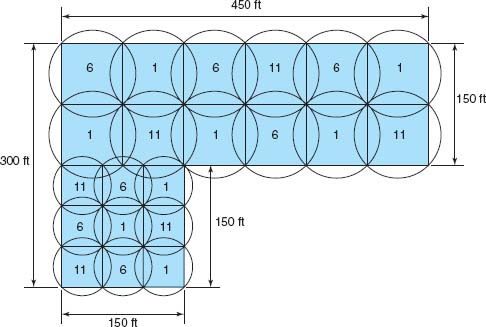
FIGURE 6.9 A Wi-Fi design (the numbers indicate the channel numbers)
Figure 6.9 shows a sample building that has two parts. The lower left corner is a 150 feet × 150 feet square, while the rest of the building is a 150 ft × 450 feet rectangle. Let's assume that the large rectangle part is an open office environment, while the smaller part uses drywall. If we put two rows of APs in the large rectangle part, we could probably space them so that each AP covered a 75-foot square. This would take a total of 12 APs for this area (see Figure 6.9). This same spacing probably won't work for the small area with drywall, so we would probably design using 50-foot squares, meaning we need 9 APs in this area (see Figure 6.9).
When designing a wireless LAN it is important to ensure that the APs don't interfere with each other. If all APs transmitted on the same frequency, the transmissions of one AP would interfere with another AP where their signals overlapped—just like what happens on your car radio when two stations are in the same frequency. Therefore, each AP is set to transmit on a different channel, very much like the different channels on your TV. Figure 6.8 shows how we could set the APs to the three commonly used channels (1, 6, and 11) so that there is minimal overlap between APs using the same channel.
After the initial design is complete, a site survey is done using a temporary AP and a computer or device that can actually measure the strength of the wireless signal. The temporary AP is installed in the area as called for in the initial design, and the computer or device is carried throughout the building measuring the strength of the signal. Actually measuring the strength of the signal in the environment is far more accurate than relying on estimated ranges.
Design becomes more difficult in a multistory building because the signals from the APs travel up and down as well as in all horizontal directions. The design must include the usual horizontal mapping but also an added vertical mapping to ensure that APs on different floors do not interfere with one another (Figure 6.10). Because floors are usually thicker than walls, signals travel further horizontally than vertically, making design a bit more difficult. It becomes even more difficult if your set of floors in a large office tower is surrounded by APs of other companies. You have to design your network not to interfere with theirs.

FIGURE 6.10 A Wi-Fi design in the three dimensions (the numbers indicate the channel numbers)
6.5.3 Designing for SOHO Environments
Most of what we have discussed so far has focused on network design in large enterprises. What about LAN design for SOHO environments? SOHO environments can be small versions of enterprise designs, or can take a very different approach.
Figure 6.11a shows a SOHO LAN designed as a small enterprise design that provides both wired and wireless Ethernet (it's in Alan's house). Virtually all of the rooms in the house are wired with 100Base-T Ethernet over Cat 5e cable, which terminates in a 24-port patch panel. You can see from the figure that only five of the rooms are actually wired from the patch panel into the 16-port switch; one of those wires connects the AP mounted in an upstairs hallway (not shown) that provides wireless access throughout the house and onto the back deck and gazebo. There is a separate router and cable modem. The AP, switch, and router are all Cisco or Linksys equipment and are the original 2001 equipment, which still work well. The cable modem is an off-brand provided by the ISP and has broken and been replaced every three years.
Figure 6.11b shows a more modern—and probably more common—SOHO LAN that provides only wireless access (it's in Alexandra's house). This has a cable modem that connects into a wireless router; the wireless router is a wireless AP, a router, and a switch for wired Ethernet all in one box. This network is simpler and cheaper because it contains fewer devices and is used only for wireless access. Alexandra doesn't have a desktop computer at home, but she could easily connect one if she wanted by adding a wireless NIC into a desktop; a 802.11n WLAN provides ample capacity for a small SOHO network.

6.6 IMPROVING LAN PERFORMANCE
When LANs had only a few users, performance was usually very good. Today, however, when most computers in an organization are on LANs, performance can be a problem. Performance is usually expressed in terms of throughput (the total amount of user data transmitted in a given time period). In this section, we discuss how to improve throughput. We focus on dedicated-server networks because they are the most commonly used type of LANs, but many of these concepts also apply to peer-to-peer networks.
To improve performance, you must locate the bottleneck, the part of the network that is restricting the data flow. Generally speaking, the bottleneck will lie in one of two places. The first is the network server. In this case, the client computers have no difficulty sending requests to the network server, but the server lacks sufficient capacity to process all the requests it receives in a timely manner. The second location is the network circuit, connecting the LAN to the corporate BN. In this case, the server can easily process all the client requests it receives, but the circuit lacks enough capacity to transmit all the requests to the server.
6.3 ERROR CONTROL IN WIRED ETHERNET
TECHNICAL FOCUS
Ethernet provides a strong error control method using stop and wait ARQ with a CRC-32 error detection field (see Chapter 4). However, the normal way of installing wired Ethernet doesn't use stop and wait ARQ.
In the early days of Ethernet, LAN environments were not very reliable, so error control was important. However, today's wired Ethernet LANs are very reliable; errors seldom occur. Stop and wait ARQ uses considerable network capacity because every time a frame is transmitted, the sender must stop and wait for the receiver to send an acknowledgment. By eliminating the need to stop and wait and the need to send acknowledgments, Ethernet can significantly improve network performance—almost doubling the number of messages that can be transmitted in the same time period. Ethernet does still add the CRC and does still check it for errors, but any frame with an error is simply discarded.
If Ethernet doesn't provide error control, then higher layers in the network model must. In general, TCP is configured to provide error control by using continuous ARQ (see Chapter 5) to ensure that all frames that have been sent are actually received at the final destination. If a frame with an error is discarded by Ethernet, TCP will recognize that a frame has been lost and ask the sender to retransmit. This moves responsibility for error control to the edges of the network (i.e., the sender and receiver) rather than making every computer along the way responsible for ensuring reliable message delivery.
The first step in improving performance, therefore, is to identify whether the bottleneck lies in the circuit or the server. To do so, you simply watch the utilization of the server during periods of poor performance. If the server utilization is high (e.g., 60 to 100 percent), then the bottleneck is the server; it cannot process all the requests it receives in a timely manner. If the server utilization is low during periods of poor performance (e.g., 10 to 40 percent), then the problem lies with the network circuit; the circuit cannot transmit requests to the server as quickly as necessary. Things become more difficult if utilization is in the midrange (e.g., 40 to 60 percent). This suggests that the bottleneck may shift between the server and the circuit depending on the type of request, and it suggests that both should be upgraded to provide the best performance.
Now we will focus attention on ways to improve the server and the circuit to remove bottlenecks. These actions address only the supply side of the equation—that is, increasing the capacity of the LAN as a whole. The other way to reduce performance problems is to attack the demand side: reduce the amount of network use by the clients, which we also discuss. Figure 6.12 provides a performance checklist.
6.6.1 Improving Server Performance
Improving server performance can be approached from two directions simultaneously: software and hardware.
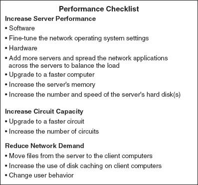
FIGURE 6.12 Improving local area network performance
Software The NOS is the primary software-based approach to improving network performance. Some NOSs are faster than others, so replacing the NOS with a faster one will improve performance.
Each NOS provides a number of software settings to fine-tune network performance. Depending on the number, size, and type of messages and requests in your LAN, different settings can have a significant effect on performance. The specific settings differ by NOS but often include things such as the amount of memory used for disk caches, the number of simultaneously open files, and the amount of buffer space.
Hardware One obvious solution if your network server is overloaded is to buy a second server (or more). Each server is then dedicated to supporting one set of application software (e.g., one handles email, another handles the financial database, and another stores customer records). The bottleneck can be broken by carefully identifying the demands each major application software package places on the server and allocating them to different servers.
Sometimes, however, most of the demand on the server is produced by one application that cannot be split across several servers. In this case, the server itself must be upgraded. The first place to start is with the server's CPU. Faster CPUs mean better performance. If you are still using an old computer as a LAN server, this may be the answer; you probably need to upgrade to the latest and greatest. Clock speed also matters: the faster, The better. Most computers today also come with CPU-cache (a very fast memory module directly connected to the CPU). Increasing the cache will increase CPU performance.
A second bottleneck is the amount of memory in the server. Increasing the amount of memory increases the probability that disk caching will work, thus increasing performance.
A third bottleneck is the number and speed of the hard disks in the server. The primary function of the LAN server is to process requests for information on its disks. Slow hard disks give slow network performance. The obvious solution is to buy the fastest disk drive possible. Even more important, however, is the number of hard disks. Each computer hard disk has only one read/write head, meaning that all requests must go through this one device. By using several smaller disks rather than one larger disk (e.g., five 200 gigabyte disks rather than one 1 terabyte disk), you now have more read/write heads, each of which can be used simultaneously, dramatically improving throughput. A special type of disk drive called RAID (redundant array of inexpensive disks) builds on this concept and is typically used in applications requiring very fast processing of large volumes of data, such as multimedia. Of course, RAID is more expensive than traditional disk drives, but costs have been shrinking. RAID can also provide fault tolerance, which is discussed in Chapter 10.
Several vendors sell special-purpose network servers that are optimized to provide extremely fast performance. Many of these provide RAID and use symmetric multiprocessing (SMP) that enables one server to use up to 16 CPUs. Such servers provide excellent performance but cost more (often $5,000 to $15,000).
6.6.2 Improving Circuit Capacity
Improving the capacity of the circuit means increasing the volume of simultaneous messages the circuit can transmit from network clients to the server(s). One obvious approach is simply to buy a bigger circuit. For example, if you are now using a 100Base-T LAN, upgrading to 1000Base-T LAN will improve capacity. Or if you have 802.11g, then upgrade to 802.11n.
The other approach is to segment the network. If there is more traffic on a LAN than it can handle, you can divide the LAN into several smaller segments. Breaking a network into smaller parts is called network segmentation. In a wired LAN, this means adding one of more new switches and spreading the computers across these new switched. In a wireless LAN, this means adding more access points that operate on different channels. If wireless performance is significantly worse than expected, then it is important to check for sources of interference near the AP and the computers such as Bluetooth devices and cordless phones.
6.6.3 Reducing Network Demand
One way to reduce network demand is to move files to client computers. Heavily used software packages that continually access and load modules from the network can place unusually heavy demands on the network. Although user data and messages are often only a few kilobytes in size, today's software packages can be many megabytes in size. Placing even one or two such applications on client computers can greatly improve network performance (although this can create other problems, such as increasing the difficulty in upgrading to new versions of the software).
Most organizations now provide both wired and wireless networks, so another way to reduce demand is to shift it from wired networks to wireless networks, or vice versa, depending upon which has the problem. For example, you can encourage wired users to go wireless, or install wired Ethernet jacks in places where wireless users often sit.
Because the demand on most LANs is uneven, network performance can be improved by attempting to move user demands from peak times to off-peak times. For example, early morning and after lunch are often busy times when people check their email. Telling network users about the peak times and encouraging them to change their habits may help; however, in practice, it is often difficult to get users to change. Nonetheless, finding one application that places a large demand on the network and moving it can have a significant impact (e.g., printing several thousand customer records after midnight).
6.7 IMPLICATIONS FOR MANAGEMENT
As LANs have standardized on Ethernet, local area networking technology has become a commodity in most organizations. As with most commodities, the cost of LAN equipment (i.e., network interface cards, cabling, hubs, and switches) has dropped significantly. Some vendors are producing high-quality equipment while some new entrants into the market are producing equipment that meets standards but creates opportunities for problems because it lacks the features of more established brands. It becomes difficult for LAN managers to explain to business managers why its important to purchase higher-quality, more expensive equipment when low-cost “standardized” equipment is available.
Most SOHO users are moving quickly to wireless, which means that wired Ethernet is a legacy technology for small SOHO devices; there is little profit to be made in this market, and many manufacturers will abandon it. We will see a rise in the sales of wireless cards for desktop computers and desktop computers targeted for sale to the SOHO market will come standard with wireless cards in addition to the wired Ethernet cards we see today.
Decreasing costs for LAN equipment also means that network enabled microprocessor controlled devices that have not normally been thought of as computer technology is becoming less expensive. Therefore, we have seen devices such as copiers turned into network printers and scanners. This trend will increase as electrical appliances such as refrigerators and ovens become network devices. Don't laugh; networked vending machines are already in use.
SUMMARY
Why Use a LAN? The two basic reasons for developing a LAN are information sharing and resource sharing. Information sharing refers to business needs that require users to access the same data files, exchange information via email, or search the Internet for information, as discussed in Chapter 2. Resource sharing refers to one computer sharing a hardware device (e.g., a printer) or software package with other computers on the network. The main benefit of resource sharing is cost savings whereas the main benefit of information sharing is improved decision making.
Dedicated-Server versus Peer-to-Peer Networks A dedicated-server LAN has one computer that acts as the network server. It can connect with almost any other network, handle very large databases, and use sophisticated LAN software. Moreover, high-end dedicated-server LANs can be interconnected easily to form enterprisewide networks or, in some cases, replace the host mainframe central computer. Common types of dedicated servers include Web servers, application servers, file servers, database servers, print servers, and remote access servers. All computers on a peer-to-peer LAN run special network software that enables them to function both as a client and as a server.
LAN Components The NIC enables the computer to be physically connected to the network and provides the physical layer connection among the computers. Wired LANs use UTP wires, STP wires, and/or fiber-optic cable. Network hubs and switches provide an easy way to connect network cables and act as repeaters. Wireless NICs provide radio connections to access points that link wireless computers into the wired network. The NOS is the software that performs the functions associated with the data link and the network layers and interacts with the application software and the computer's own operating system. Every NOS provides two sets of software: one that runs on the network server(s) and one that runs on the network client(s). A network profile specifies what resources on each server are available for network use by other computers and which devices or people are allowed what access to the network.
Ethernet (IEEE 802.3) Ethernet, the most commonly used LAN protocol in the world, uses a contention-based media access technique called CSMA/CD. There are many different types of Ethernet that use different network cabling (e.g., 10Base-T, 100Base-T, 1000Base-T, 10 GbE). Switches are preferred to hubs because they are significantly faster.
Wireless Ethernet Wireless Ethernet (often called Wi-Fi) is the most common type of wireless LAN. It uses physical star/logical bus topology with both controlled and contention-based media access control. 802.11n, the newest version, provides 200 Mbps over three channels or faster speeds over fewer channels.
Best Practice LAN Design Most organizations install 100Base-T or 10/100/1000 Ethernet as their primary LAN and also provide wireless 802.11n as an overlay network. For SOHO networks, the best LAN choice may be wireless.
Improving LAN Performance Every LAN has a bottleneck, a narrow point in the network that limits the number of messages that can be processed. Generally speaking, the bottleneck will lie in either the network server or the network circuit. Server performance can be improved with a faster NOS that provides better disk caching, by buying more servers and spreading applications among them, or by upgrading the server's CPU, memory, NIC, and the speed and number of its hard disks. Circuit capacity can be improved by using faster technologies (100Base-T rather than 10Base-T) and by segmenting the network into several separate LANs by adding more switches or access points. Overall LAN performance also can be improved by reducing the demand for the LAN by moving files off the LAN, moving users from wired Ethernet to wireless or vice versa, and by shifting users’ routines.
KEY TERMS
access point (AP)
Active Directory Service (ADS)
association
beacon frame
bottleneck
bus topology
cable plan
cabling
Carrier Sense Multiple Access with Collision Detection (CSMA/CD)
Carrier Sense Multiple Access with Collision Avoidance (CSMA/CA)
channel
clear to transmit (CTS)
collision
collision detection (CD)
cut-through switching
dedicated-server LAN
directional antenna
distributed coordination function (DCF)
domain controller
Ethernet
Extensible Authentication Protocol (EAP)
fiber-optic cable
file server
forwarding table
fragment-free switching
frame
hub
IEEE 802.3
IEEE 802.11
information sharing
LAN metering software
latency
layer-2 switch
lightweight directory services (LDAP)
logical topology
MAC address filtering
network-attached storage (NAS)
network operating system (NOS)
network profile
network segmentation
network server
omnidirectional antenna
overlay network
peer-to-peer network
physical carrier sense method
physical topology
point coordination function (PCF)
port
Power over Ethernet (POE)
print server
probe frame
redundant array of inexpensive disks (RAID)
request to transmit (RTS)
resource sharing
server farm
shared Ethernet
shielded twisted-pair (STP)
site survey
small office, home office (SOHO)
software audit
software piracy
Software Publishers Association (SPA)
storage area network (SAN)
store and forward switching
switching
switch
switched Ethernet
symmetric
multi-processing (SMP)
topology
twisted-pair cable
unshielded twisted-pair (UTP) cable
virtual carrier sense
warchalking
wardriving
Wi-Fi
Wi-Fi Protected Access (WPA)
Wired Equivalent Privacy (WEP)
Wireless LAN (WLAN)
10Base-T
100Base-T
1000Base-T
10/100/1000 Ethernet
1 GbE
10 GbE
40 GbE
802.11a
802.11b
802.11g
802.11i
802.11n
QUESTIONS
- Define local area network.
- What are the distinguishing features of a LAN?
- What are two reasons for developing LANs?
- What is the function of LAN metering software?
- Discuss why it is important for organizations to enforce policies restricting use of employee-owned hardware and software and unauthorized copies of software.
- Describe at least three types of servers.
- Describe the basic components of a wired LAN.
- Describe the basic components of a wireless LAN.
- What types of cables are commonly used in wired LANs?
- Compare and contrast category 5 UTP, category 5e UTP, and category 5 STP.
- What is a cable plan and why would you want one?
- What does a NOS do? What are the major software parts of a NOS?
- How does wired Ethernet work?
- How does a logical topology differ from a physical topology?
- Briefly describe how CSMA/CD works.
- Explain the terms 100Base-T, 100Base-F, 1000Base-T, 10 GbE, and 10/100/1000 Ethernet.
- How do Ethernet switches know where to send the frames they receive? Describe how switches gather and use this knowledge.
- Compare and contrast cut-through, store and forward, and fragment-free switching.
- Compare and contrast the two types of antennas.
- How does Wi-Fi perform media access control?
- How does Wi-Fi differ from shared Ethernet in terms of topology, media access control, and error control, Ethernet frame?
- Explain how CSMA/CA DCF works.
- Explain how CSMA/CA PCF works.
- Explain how association works in WLAN.
- What are the best practice recommendations for wired LAN design?
- What are the best practice recommendations for WLAN design?
- What is a site survey and why is it important?
- How do you decide how many APs are needed and where they should be placed for best performance?
- What is a bottleneck and how can you locate one?
- Describe three ways to improve network performance on the server.
- Many of the wired and wireless LANs share the same or similar components (e.g., error control). Why?
- As WLANs become more powerful, what are the implications for networks of the future? Will wired LANS still be common or will we eliminate wired offices?
EXERCISES
6-1. Survey the LANs used in your organization. Are they Ethernet or Wi-Fi? Why?
6-2. Document one LAN (or LAN segment) in detail. What devices are attached, what cabling is used, and what is the topology? What does the cable plan look like?
6-3. You have been hired by a small company to install a simple LAN for their 18 Windows computers. Develop a simple LAN and determine the total cost; that is, select the cables, hubs/switches, and NICs and price them. Assume that the company has no network today and that the office is small enough that you don't need to worry about cable length.
MINI-CASES
I. Designing a New Ethernet
One important issue in designing Ethernet lies in making sure that if a computer transmits a frame, any other computer that attempts to transmit at the same time will be able to hear the incoming frame before it stops transmitting, or else a collision might go unnoticed. For example, assume that we are on earth and send an Ethernet frame over a very long piece of category 5 wire to the moon. If a computer on the moon starts transmitting at the same time as we do on earth and finishes transmitting before our frame arrives at the moon, there will be a collision, but neither computer will detect it; the frame will be garbled, but no one will know why. So, in designing Ethernet, we must make sure that the length of cable in the LAN is shorter than the length of the shortest possible frame that can be sent. Otherwise, a collision could go undetected.
- Let's assume that the smallest possible message is 64 bytes (including the 33-byte overhead). If we use 10Base-T, how long (in meters) is a 64-byte message? While electricity in the cable travels a bit slower than the speed of light, once you include delays in the electrical equipment in transmitting and receiving the signal, the effective speed is only about 40 million meters per second. (Hint: First calculate the number of seconds it would take to transmit the frame then calculate the number of meters the signal would travel in that time, and you have the total length of the frame.)
- If we use 10 GbE, how long (in meters) is a 64-byte frame?
- The answer in part b is the maximum distance any single cable could run from a switch to one computer in a switched Ethernet LAN. How would you overcome the problem implied by this?
II. Pat's Petunias
You have been called in as a network consultant by your cousin Pat who operates a successful mail-order flower business. She is moving to a new office and wants to install a network for her telephone operators, who take phone calls and enter orders into the system. The number of operators working varies depending on the time of day and day of the week. On slow shifts, there are usually only 10 operators, whereas at peak times, there are 50. She has bids from different companies to install (1) Wi-Fi, or (2) a switched Ethernet 100Base-T network. She wants you to give her some sense of the relative performance of the alternatives so the can compare that with their different costs. What would you recommend?
III. Eureka!
Eureka! is a telephone and Internet-based concierge service that specializes in obtaining things that are hard to find (e.g., Super Bowl tickets, first-edition books from the 1500s, Fabergé eggs). It currently employs staff members who work 24 hours per day (over three shifts), with usually 5 to 7 staff members working at any given time. Staff members answer the phone and respond to requests entered on the Eureka! Web site. Much of their work is spent on the phone and on computers searching on the Internet. They have just leased a new office and are about to wire it. They have bids from different companies to install (a) a 100Base-T network, or (b) a Wi-Fi network. What would you recommend? Why?
IV. Tom's Home Automation
Your cousin Tom runs a small construction company that builds custom houses. He has just started a new specialty service that he is offering to other builders on a subcontracting basis: home automation. He provides a complete service of installing cable in all the rooms in which the homeowner wants data access and installs the necessary networking devices to provide a LAN that will connect all the computers in the house to the Internet. Most homeowners choose to install a DSL or cable modem Internet connection that provides a 1–2 Mbps from the house to the Internet. Tom has come to you for advice. What type of LAN would you recommend?
V. Sally's Shoes
Sally Smith runs a shoe store in the mall that is about 30 feet by 50 feet in size, including a small office and a storage area in the rear. The store has one inventory computer in the storage area and one computer in the office. She is replacing the two cash registers with computers that will act as cash registers but will also be able to communicate with the inventory computer. Sally wants to network the computers with a LAN. What sort of LAN design would you recommend? Draw a picture.
VI. South West State University
South West State University installed a series of four Wi-Fi omnidirectional APs spread across the ceiling of the main floor of their library. The main floor has several large, open areas plus two dozen or so small offices spread around the outside walls. The WLAN worked well for one semester, but now more students have laptops with Wi-Fi built in, and performance has deteriorated significantly. What would you recommend that they do? Be sure to support your recommendations.
VII. Household Wireless
Your sister is building a new two-story house (which measures 50 feet long by 30 feet wide) and wants to make sure that it is capable of networking her family's three computers together. She and her husband are both consultants and work out of their home in the evenings and a few days a month (each has a separate office with a computer, plus a laptop from the office that they occasionally use). The kids also have a computer in their playroom. They have several options for networking their home:
- Wire the two offices and playroom with Ethernet cat 5e cable and put in a 100Base-T switch for $40
- Install one Wi-Fi access point ($85) and put Wi-Fi cards in the three computers for $50 each (their laptops already have Wi-Fi)
- Any combination of these options
What would you recommend? Justify your recommendation.
Ubiquitous Offices provides temporary office space in cities around the country. They have a standard office layout that is a single floor with outside dimensions of 150 feet wide by 150 feet long. The interior is drywall offices. They have 100Base-T but want to add wireless access as well. How many access points would you buy, and where would you put them? Draw the office and show where the access points would go.
IX. ABC Warehouse
ABC warehouse is a single-floor facility with outside dimensions of 100 feet wide by 350 feet long. The interior is open, but there are large metal shelving units throughout the building to hold all the goods in the warehouse. How many access points would you buy, and where would you put them? Draw the warehouse and show where the access points would go.
X. Metro Motel
Metro Motel is a four-story motel on the outskirts of town. The outside dimensions of the motel are 60 feet wide by 200 feet long, and each story is about 10 feet high. Each floor (except the ground floor) has 20 rooms (drywall construction). There is a central corridor with rooms on both sides. How many access points would you buy, and where would you put them? Draw the motel and show where the access points would go.
CASE STUDY
NEXT-DAY AIR SERVICE
See the Web site.
HANDS-ON ACTIVITY 6A
Windows Peer-to-Peer Networking
In this chapter, we've discussed two types of LANs: peer-to-peer LANs and dedicated server LANs. This activity will show you how to set up a peer-to-peer LAN for your house or apartment. We first describe file sharing and then discuss printer sharing.
Windows File Sharing
Windows file sharing enables you to select folders on your computer that you can permit others users on your LAN to read and write. There are three steps to create a shared folder.
Step 1. Give your computer an Application Layer Name within a Workgroup
- Go to Settings → Control Panel → System
- Click on the Computer Name Tab
- Click Change
- Type in a New Computer Name and Workgroup Name. All computers must have the same work-group name to share files. Each computer within a workgroup must have a unique name.
Step 2. Enable File Sharing
- Go to Settings → Control Panel → Windows Firewall
- Click on the Exceptions tab
- Make sure the box in front of File and Printer Sharing is checked
- Go to Settings → Control Panel → Network Connections
- Right click on the LAN connection and click Properties
- Ensure that the box in front of File and Printer Sharing for Microsoft Networks is checked.
Step 3. Create the Shared Folder
- Open Windows Explorer
- Create a new folder
- Right click the folder name and choose Properties
- Click on the Sharing tab
- Avoid the Network Wizard and make sure the boxes in front of Share this Folder and Allow Network Users to change are checked
Once you have created a shared folder, other computers in your workgroup can access it. Move to another computer on your LAN and repeat steps 1 and 2 (and step 3 if you like). Now you can use the shared folder:
- Double click on My Network Places
- Double click on a shared folder
- Create a file (e.g., using Word) and save it in your shared directory
- Move the file(s) across computers in your work-group
If you do this on your home network, anyone with access to your network can access the files in your shared folder. It is much safer to turn off file sharing unless you intentionally want to use it (see Step 2 and make sure the boxes are not checked if you want to prevent file sharing).
Windows Printer Sharing
In the same way you can share folders with other computers in your workgroup you can share printers. To share a printer, do the following on the computer that has the printer connected to it:
- Go to Settings → Control Panel → Printers and Faxes
- Right click on a printer and select Properties
- Click on the Sharing tab
- Click on Share This Printer
Once you have done this, you can move to other computers on your LAN and install the network on them:
- Go to Settings → Control Panel → Printers and Faxes
- Click on Add a Printer
- In the Welcome to Add a Printer Wizard, click Next
- Click the Radio Button in front of A Network Printer and click Next
- Click the Radio Button in front of Browse for a Printer and click Next
- Select the Network Printer and click Next
- You can make this printer your default printer or not, and click Next
Deliverables
- Do a print screen of Windows Explorer to show the folders on another computer you can access.
- Do a print screen to show you can print to the networked printer.
HANDS-ON ACTIVITY 6B
Tracing Ethernet
TracePlus Ethernet is a network monitoring tool that enables you to see how much network capacity you are using. If you're working from home with a broadband Internet connection, you'll be surprised how little of the Ethernet capacity you're actually using. Your Ethernet connection is probably 100 Mbps (or 200 Mbps if you're using wireless), while your broadband connection is only 1.5 Mbps. The bottleneck is the broadband connection, so you use only 1–2 percent of your Ethernet capacity.
- Download and install TracePlus. A free trial version of TracePlus is available at Tech Republic (software.techrepublic.com). The URL as we write this is as follows, but it might move, so if this link doesn't work, search on the Tech Republic site: software.techrepublic.com.com/download.aspx?docid=234509.
- Start TracePlus and monitor your network. Leave it open in one part of your screen as you surf the Internet, check e-mail, or watch a video.
Figure 6.13 shows a sample TracePlus screen while I was surfing the Internet and checking e-mail with Microsoft Outlook. The dashboard at the bottom of the screen shows the real-time usage. You can see that when I took this screen shot, my computer was sending and receiving about 100 packets per second (or if you prefer, 100 frames per second), for a total of just under 1 Mbps of data. This is less than 1 percent of the total Ethernet bandwidth (i.e., network capacity), because I have switched 100Base-T on my computer. The dashboard also shows that I'm sending and receiving almost no broadcast or multicast data.
Immediately above the dashboard is the summary for my computer (192.1681.104 (Alan 2)). In the 2 minutes and 30 seconds of monitoring, my computer received 1,875 inbound packets with a total of 2.236 megabytes of data for a utilization of 0.118 percent. The average bits per second was about 118 Kbps. During the same time, my computer sent slightly fewer outbound packets (1,232), but the average packet was about ten times smaller because the total amount of data sent was only 218,569 bytes. Most packets were in the 128–511 bytes in length, but some were smaller and some were larger.
The Nodes tab in the upper right of the screen shows the nodes on my network that TracePlus can monitor. These include my computer (Alan2), a second computer (Orcelia), my router (192.168.1.1), a wireless access point (Aironet) with two connections (into the LAN and out to the wireless LAN), and the Indiana University VPN server (because I had my VPN connected; Chapter 11 discusses VPNs). You can see that all of these devices have little utilization (under 1 percent), as well as the total number of packets these devices have sent and received. You can click through the other tabs in this area to see the packet distribution.
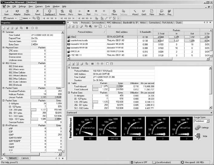
The panel on the left of the screen shows additional information about the types of packets, errors, and packet sizes.
Deliverables
- How many packets your computer can send and receive?
- What is the total data rate on your network?
- What is your network utilization?
HANDS-ON ACTIVITY 6C
War-Driving and War-Walking
Wireless LANS are often not secure. It is simple to bring your laptop computer into a public area and listen for wireless networks. This is called War-Driving (if you are in a car) or War-Walking (if you're walking). As long as you do not attempt to use any networks without authorization, War-Driving and War-Walking are quite legal. There are many good software tools available for War-Driving. My favorites are Net Stumbler (available from www.netstumbler.com) or Wireless NetView (available from www.nirsoft.com). Both are simple to use, yet powerful. Net Stumbler historically has been the most commonly used tool, but some users have reported problems using it on Windows 7.
The first step is to download and install the Net Stumbler software on a laptop computer that has wireless capability. The software is available at www.netstumbler.com. Once you have installed the software, simply walk or drive to a public area and start it up. Figure 6.14 shows an example of the seven networks I discovered in my home town of Bloomington, Indiana when I walked through one building downtown using NetStumbler. For each network, Net Stumbler displays the MAC address of the access point (or physical address if you prefer to use that term). It shows the SSID, the channel number the AP is configured to use, the speed of the network, the access point vendor (which can be disabled by the access point owner to increase security), and the type of encryption in use (if any). It also shows the signal strength both by color coding the network (green is good) and by showing the signal-to-noise ratio (SNR) and the strength of the signal and the noise.
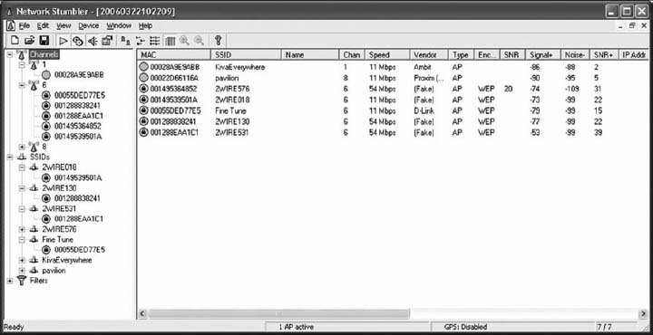
FIGURE 6.14 NetStumbler shows the networks in one downtown building
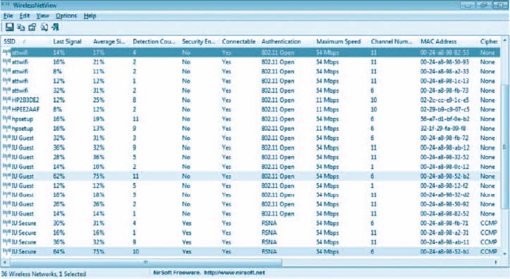
FIGURE 6.15 Wireless NetView shows the networks in Alan's office at Indiana University
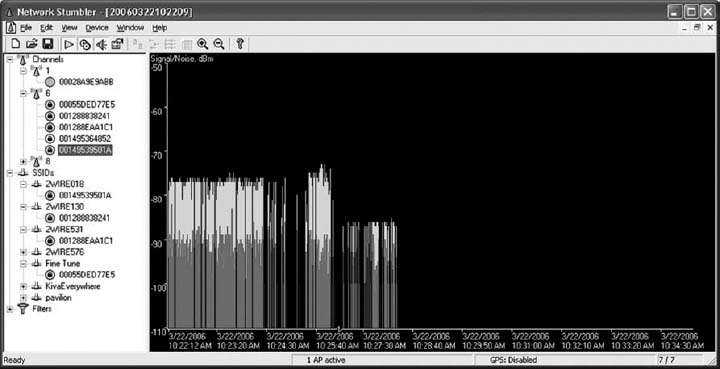
FIGURE 6.16 Changes in signal strength
Figure 6.15 shows a similar display from Wireless NetView when it was used in Alan's office at Indiana University. Wireless NetView presents the same basic information as Net Stumbler. Notice how many networks there are that touch this one location, although the signal strength is too weak to be used for most of them.
In these figures, you can see a mix of WLANs, both 11 Mbps and 54 Mbps. The channels we usually use for 802.11b and 802.11g are channels 1, 6, and 11. In this figure, you'll see a mix of channels 1 and 6, plus one channel 8 and one channel 10 WLAN. 802.11b and 802.11g can be configured to use four channels (1, 4, 8, and 11), although the channels overlap to some extent. So if you run an AP on channel 1 and another on channel 4, there will be some interference between the two APs. The best practice recommendation that most companies follow is to use a three-channel configuration. In Figure 6.14, you can see that most companies are using the three-channel configuration, but one is not; it's using the four-channel configuration.
If you click on an access point in the left panel, Net Stumbler shows you a real time graph of the signal and noise for that network. Figure 6.16 shows how the signal strength changed for one of the networks as I walked through the building. The left edge of the graph shows that the network started with a good signal (the green or light colored area at the top of the bars) was much higher than the noise (the red or dark colored area at the bottom of the bars). As I walked around, the signal became weaker; the signal was barely higher than the noise. As I walked more, the signal dropped so that it was too weak for me to detect it from the noise.
Deliverables
- Capture a snapshot for the screen having all the information related to the various network connections that you collected during your warwalking.
- How many networks kept the original/default SSID? Why could this be a security problem?
- How many networks were secure?
- What is your overall assessment of the WLAN usage with respect to security?
1 The formal specification for Ethernet is provided in the 802.3 standard on the IEEE standards Web site. The URL is grouper.ieee.org/groups/802/3.
2 It would be reasonable to think that 1000Base-T would require 10 category 5 cables because 10 × 100Mps = 1,000 Mbps. However, it is possible to push 100-Mbps cables to faster speeds over shorter distances. Therefore, the category 5 flavor of 1000Base-T uses only 4 pairs of category 5 (i.e., 8 wires) running at 125 Mbps, but over shorter distances than would be normal for 100Base-T. A special form of category 5 cable (called category 5e) has been developed to meet the special needs of 1000Base-T. This same approach is used to run 10 GbE over category 5.