
CHAPTER 4
DATA LINK LAYER
THE DATA link layer (also called layer 2) is responsible for moving a message from one computer or network device to the next computer or network device in the overall path from sender or receiver. It controls the way messages are sent on the physical media. Both the sender and receiver have to agree on the rules, or protocols, that govern how they will communicate with each other. A data link protocol determines who can transmit at what time, where a message begins and ends, and how a receiver recognizes and corrects a transmission error. In this chapter, we discuss these processes, as well as several important sources of errors.
OBJECTIVES ![]()
- Understand the role of the data link layer
- Become familiar with two basic approaches to controlling access to the media
- Become familiar with common sources of error and their prevention
- Understand three common error detection and correction methods
- Become familiar with several commonly used data link protocols
CHAPTER OUTLINE ![]()
4.3.4 Error Correction via Retransmission
4.3.5 Forward Error Correction
4.3.6 Error Control in Practice
4.4.1 Asynchronous Transmission
4.4.2 Synchronous Transmission
4.6 IMPLICATIONS FOR MANAGEMENT
4.1 INTRODUCTION
In Chapter 1, we introduced the concept of layers in data communications. The data link layer sits between the physical layer (hardware such as the circuits, computers, and multiplexers described in Chapter 3) and the network layer (that performs addressing and routing, as described in Chapter 5).
The data link layer is responsible for sending and receiving messages to and from other computers. Its job is to reliably move a message from one computer over one circuit to the next computer where the message needs to go.
The data link layer performs two main functions, and therefore is often divided into two sublayers. The first sublayer (called the logical link control [LLC] sublayer) is the data link layer's connection to the network layer above it. At the sending computer, the LLC sublayer software is responsible for communicating with the network layer software (e.g., IP) and for taking the network layer Protocol Data Unit (PDU)—usually an IP packet—and surrounding it with a data link layer PDU—often an Ethernet frame. At the receiving computer, the LLC sublayer software removes the data link layer PDU and passes the message it contains (usually an IP packet) to the network layer software.
The second sublayer (called the media access control [MAC] sublayer) controls the physical hardware. The MAC sublayer software at the sending computer controls how and when the physical layer converts bits into the physical symbols that are sent down the circuit. At the receiving computer, the MAC sublayer software takes the data link layer PDU from the LLC sublayer, converts it into a stream of bits, and controls when the physical layer actually transmits the bits over the circuit. At the receiving computer, the MAC sublayer receives a stream of bits from the physical layer and translates it into a coherent PDU, ensures that no errors have occurred in transmission, and passes the data link layer PDU to the LLC sublayer.
Both the sender and receiver have to agree on the rules or protocols that govern how their data link layers will communicate with each other. A data link protocol performs three functions:
- Controls when computers transmit (media access control)
- Detects and corrects transmission errors (error control)
- Identifies the start and end of a message by using a PDU (message delineation)
4.2 MEDIA ACCESS CONTROL
Media access control refers to the need to control when computers transmit. With point-to-point full-duplex configurations, media access control is unnecessary because there are only two computers on the circuit and full duplex permits either computer to transmit at any time.
Media access control becomes important when several computers share the same communication circuit, such as a point-to-point configuration with a half-duplex configuration that requires computers to take turns, or a multipoint configuration in which several computers share the same circuit. Here, it is critical to ensure that no two computers attempt to transmit data at the same time—but if they do, there must be a way to recover from the problem. There are two fundamental approaches to media access control: contention and controlled access.
4.2.1 Contention
With contention computers wait until the circuit is free (i.e., no other computers are transmitting) and then transmit whenever they have data to send. Contention is commonly used in Ethernet LANs.
As an analogy, suppose that you are talking with some friends. People listen and if no one is talking they can talk. If you want to say something, you wait until the speaker is done and then you try to talk. Usually, people yield to the first person who jumps in at the precise moment the previous speaker stops. Sometimes two people attempt to talk at the same time, so there must be some technique to continue the conversation after such a verbal collision occurs.
4.2.2 Controlled Access
Most wireless LANS use controlled access. In this case, the wireless access point controls the circuit and determines which clients can transmit at what time. There are two commonly used controlled access techniques: access requests and polling.
With the access request technique, client computers that want to transmit send a request to transmit to the device that is controlling the circuit (e.g., the wireless access point). The controlling device grants permission for one computer at a time to transmit. When one computer has permission to transmit, all other computers wait until that computer has finished, and then, if they have something to transmit, they use a contention technique to send an access request.
The access request technique is like a classroom situation in which the instructor calls on the students who raise their hands. The instructor acts like the controlling access point. When they want to talk, students raise their hands and the instructor recognizes them so they can contribute. When they have finished, the instructor again takes charge and allows someone else to talk. And of course, just like in a classroom, the wireless access point can choose to transmit whenever it likes.
Polling is the process of sending a signal to a client computer that gives it permission to transmit. With polling, the clients store all messages that need to be transmitted. Periodically, the controlling device (e.g., a wireless access point) polls the client to see if it has data to send. If the client has data to send, it does so. If the client has no data to send, it responds negatively, and the controller asks another client if it has data to send.
There are several types of polling. With roll-call polling, the controller works consecutively through a list of clients, first polling client 1, then client 2, and so on, until all are polled. Roll-call polling can be modified to select clients in priority so that some get polled more often than others. For example, one could increase the priority of client 1 by using a polling sequence such as 1, 2, 3, 1, 4, 5, 1, 6, 7, 1, 8, 9.
Typically, roll-call polling involves some waiting because the controller has to poll a client and then wait for a response. The response might be an incoming message that was waiting to be sent, a negative response indicating nothing is to be sent, or the full “time-out period” may expire because the client is temporarily out of service (e.g., it is malfunctioning or the user has turned it off). Usually, a timer “times out” the client after waiting several seconds without getting a response. If some sort of fail-safe time-out is not used, the circuit poll might lock up indefinitely on an out-of-service client.
With hub polling (often called token passing), one device starts the poll and passes it to the next computer on the multipoint circuit, which sends its message and passes the poll to the next. That computer then passes the poll to the next, and so on, until it reaches the first computer, which restarts the process again.
4.2.3 Relative Performance
Which media access control approach is best: controlled access or contention? There is no simple answer. The key consideration is throughput—which approach will permit the most amount of user data to be transmitted through the network.
In general, contention approaches work better than controlled approaches for small networks that have low usage. In this case, each computer can transmit when necessary, without waiting for permission. Because usage is low, there is little chance of a collision. In contrast, computers in a controlled access environment must wait for permission, so even if no other computer needs to transmit, they must wait for the poll.
The reverse is true for large networks with high usage: controlled access works better. In high-volume networks, many computers want to transmit, and the probability of a collision using contention is high. Collisions are very costly in terms of throughput because they waste circuit capacity during the collision and require both computers to retransmit later. Controlled access prevents collisions and makes more efficient use of the circuit, and although response time does increase, it does so more gradually (Figure 4.1).
The key to selecting the best access control technique is to find the crossover point between controlled and contention. Although there is no one correct answer, because it depends on how many messages the computers in the network transmit, most experts believe that the crossover point is often around 20 computers (lower for busy computers, higher for less-busy computers). For this reason, when we build shared multipoint circuits like those often used in LANs or wireless LANs, we try to put no more than 20 computers on any one shared circuit.

FIGURE 4.1 Relative response times
4.3 ERROR CONTROL
Before learning the control mechanisms that can be implemented to protect a network from errors, you should realize that there are human errors and network errors. Human errors, such as a mistake in typing a number, usually are controlled through the application program. Network errors, such as those that occur during transmission, are controlled by the network hardware and software.
There are two categories of network errors: corrupted data (data that have been changed) and lost data. Networks should be designed to (1) prevent, (2) detect, and (3) correct both corrupted data and lost data. We begin by examining the sources of errors and how to prevent them and then turn to error detection and correction.
Network errors are a fact of life in data communications networks. Depending on the type of circuit, they may occur every few hours, minutes, or seconds because of noise on the lines. No network can eliminate all errors, but most errors can be prevented, detected, and corrected by proper design. IXCs that provide data transmission circuits provide statistical measures specifying typical error rates and the pattern of errors that can be expected on the circuits they lease. For example, the error rate might be stated as 1 in 500,000, meaning there is 1 bit in error for every 500,000 bits transmitted.
Normally, errors appear in bursts. In a burst error, more than 1 data bit is changed by the error-causing condition. In other words, errors are not uniformly distributed in time. Although an error rate might be stated as 1 in 500,000, errors are more likely to occur as 100 bits every 50,000,000 bits. The fact that errors tend to be clustered in bursts rather than evenly dispersed is both good and bad. If the errors were not clustered, an error rate of 1 bit in 500,000 would make it rare for 2 erroneous bits to occur in the same character. Consequently, simple character-checking schemes would be effective at detecting errors. When errors are #ore or less evenly distrib#ted, it is not di#ficult to gras# the me#ning even when the error #ate is high, as it is in this #entence (1 charac#er in 20). But burst errors are the rule rather than the exception, often obliterating 100 or more bits at a time. This makes it more difficult to recover the meaning, so more reliance must be placed on error detection and correction methods. The positive side is that there are long periods of error-free transmission, meaning that very few messages encounter errors.
4.3.1 Sources of Errors
Line noise and distortion can cause data communication errors. The focus in this section is on electrical media such as twisted-pair wire and coaxial cable, because they are more likely to suffer from noise than are optical media such as fiber-optic cable. In this case, noise is undesirable electrical signals (for fiber-optic cable, it is undesirable light). Noise is introduced by equipment or natural disturbances, and it degrades the performance of a communication circuit. Noise manifests itself as extra bits, missing bits, or bits that have been “flipped” (i.e., changed from 1 to 0 or vice versa). Figure 4.2 summarizes the major sources of error and ways to prevent them. The first six sources listed there are the most important; the last three are more common in analog rather than digital circuits.
White noise or Gaussian noise (the familiar background hiss or static on radios and telephones) is caused by the thermal agitation of electrons and therefore is inescapable. Even if the equipment were perfect and the wires were perfectly insulated from any and all external interference, there still would be some white noise. White noise usually is not a problem unless it becomes so strong that it obliterates the transmission. In this case, the strength of the electrical signal is increased so it overpowers the white noise; in technical terms, we increase the signal-to-noise ratio.

FIGURE 4.2 Sources of errors and ways to minimize them
Impulse noise (sometimes called spikes) is the primary source of errors in data communications. It is heard as a click or a crackling noise and can last as long as 1/100 of a second. Such a click does not really affect voice communications, but it can obliterate a group of data, causing a burst error. At 1.5 Mbps, 15,000 bits would be changed by a spike of 1/100 of a second. Some of the sources of impulse noise are voltage changes in adjacent lines, lightning flashes during thunderstorms, fluorescent lights, and poor connections in circuits.
Cross-talk occurs when one circuit picks up signals in another. A person experiences cross-talk during telephone calls when she or he hears other conversations in the background. It occurs between pairs of wires that are carrying separate signals, in multiplexed links carrying many discrete signals, or in microwave links in which one antenna picks up a minute reflection from another antenna. Cross-talk between lines increases with increased communication distance, increased proximity of the two wires, increased signal strength, and higher-frequency signals. Wet or damp weather can also increase cross-talk. Like white noise, cross-talk has such a low signal strength that it normally is not bothersome.
Echoes are the result of poor connections that cause the signal to reflect back to the transmitting equipment. If the strength of the echo is strong enough to be detected, it causes errors. Echoes, like cross-talk and white noise, have such a low signal strength that they normally are not bothersome. Echoes can also occur in fiber-optic cables when connections between cables are not properly aligned.
Attenuation is the loss of power a signal suffers as it travels from the transmitting computer to the receiving computer. Some power is absorbed by the medium or is lost before it reaches the receiver. As the medium absorbs power, the signal becomes weaker, and the receiving equipment has less and less chance of correctly interpreting the data. This power loss is a function of the transmission method and circuit medium. High frequencies lose power more rapidly than do low frequencies during transmission, so the received signal can thus be distorted by unequal loss of its component frequencies. Attenuation increases as frequency increases or as the diameter of the wire decreases.
Intermodulation noise is a special type of cross-talk. The signals from two circuits combine to form a new signal that falls into a frequency band reserved for another signal. This type of noise is similar to harmonics in music. On a multiplexed line, many different signals are amplified together, and slight variations in the adjustment of the equipment can cause intermodulation noise. A maladjusted modem may transmit a strong frequency tone when not transmitting data, thus producing this type of noise.
In general, errors are more likely to occur in wireless, microwove, or satellite transmission than transmission through cables. Therefore, error detection is more important when using radiated media than guided media.
4.3.2 Error Prevention
Obviously, error prevention is very important. There are many techniques to prevent errors (or at least reduce them), depending on the situation. Shielding (protecting wires by covering them with an insulating coating) is one of the best ways to prevent impulse noise, cross-talk, and intermodulation noise. Many different types of wires and cables are available with different amounts of shielding. In general, the greater the shielding, the more expensive the cable and the more difficult it is to install.
Moving cables away from sources of noise (especially power sources) can also reduce impulse noise, cross-talk, and intermodulation noise. For impulse noise, this means avoiding lights and heavy machinery. Locating communication cables away from power cables is always a good idea. For cross-talk, this means physically separating the cables from other communication cables.
Cross-talk and intermodulation noise is often caused by improper multiplexing. Changing multiplexing techniques (e.g., from FDM to TDM) or changing the frequencies or size of the guardbands in FDM can help.
Many types of noise (e.g., echoes, white noise) can be caused by poorly maintained equipment or poor connections and splices among cables. This is particularly true for echo in fiber-optic cables, which is almost always caused by poor connections. The solution here is obvious: Tune the transmission equipment and redo the connections.
To avoid attenuation, telephone circuits have repeaters or amplifiers spaced throughout their length. The distance between them depends on the amount of power lost per unit length of the transmission line. An amplifier takes the incoming signal, increases its strength, and retransmits it on the next section of the circuit. They are typically used on analog circuits such as the telephone company's voice circuits. The distance between the amplifiers depends on the amount of attenuation, although 1- to 10-mile intervals are common. On analog circuits, it is important to recognize that the noise and distortion are also amplified, along with the signal. This means some noise from a previous circuit is regenerated and amplified each time the signal is amplified.
Repeaters are commonly used on digital circuits. A repeater receives the incoming signal, translates it into a digital message, and retransmits the message. Because the message is recreated at each repeater, noise and distortion from the previous circuit are not amplified. This provides a much cleaner signal and results in a lower error rate for digital circuits.
4.1 FINDING THE SOURCE OF IMPULSE NOISE
MANAGEMENT FOCUS
Several years ago, the University of Georgia radio station received FCC (Federal Communications Commission) approval to broadcast using a stronger signal. Immediately after the station started broadcasting with the new signal, the campus backbone network (BN) became unusable because of impulse noise. It took two days to link the impulse noise to the radio station, and when the radio station returned to its usual broadcast signal, the problem disappeared.
However, this was only the first step in the problem. The radio station wanted to broadcast at full strength, and there was no good reason for why the stronger broadcast should affect the BN in this way. After two weeks of effort, the problem was discovered. A short section of the BN ran above ground between two buildings. It turned out that the specific brand of outdoor cable we used was particularly tasty to squirrels. They had eaten the outer insulating coating off of the cable, making it act like an antennae to receive the radio signals. The cable was replaced with a steel-coated armored cable so the squirrels could not eat the insulation. Things worked fine when the radio station returned to its stronger signal.
4.3.3 Error Detection
It is possible to develop data transmission methodologies that give very high error-detection performance. The only way to do error-detection is to send extra data with each message. These error-detection data are added to each message by the data link layer of the sender on the basis of some mathematical calculations performed on the message (in some cases, error-detection methods are built into the hardware itself). The receiver performs the same mathematical calculations on the message it receives and matches its results against the error-detection data that were transmitted with the message. If the two match, the message is assumed to be correct. If they don't match, an error has occurred.
In general, the larger the amount of error-detection data sent, the greater the ability to detect an error. However, as the amount of error-detection data is increased, the throughput of useful data is reduced, because more of the available capacity is used to transmit these error-detection data and less is used to transmit the actual message itself. Therefore, the efficiency of data throughput varies inversely as the desired amount of error detection is increased.
Three well-known error-detection methods are parity checking, checksum, and cyclic redundancy checking.
Parity Checking One of the oldest and simplest error-detection methods is parity. With this technique, one additional bit is added to each byte in the message. The value of this additional parity bit is based on the number of 1’s in each byte transmitted. This parity bit is set to make the total number of 1’s in the byte (including the parity bit) either an even number or an odd number. Figure 4.3 gives an example.
A little thought will convince you that any single error (a switch of a 1 to a 0 or vice versa) will be detected by parity, but it cannot determine which bit was in error. You will know an error occurred, but not what the error was. But if two bits are switched, the parity check will not detect any error. It is easy to see that parity can detect errors only when an odd number of bits have been switched; any even number of errors cancel one another out. Therefore, the probability of detecting an error, given that one has occurred, is only about 50 percent. Many networks today do not use parity because of its low error-detection rate. When parity is used, protocols are described as having odd parity or even parity.
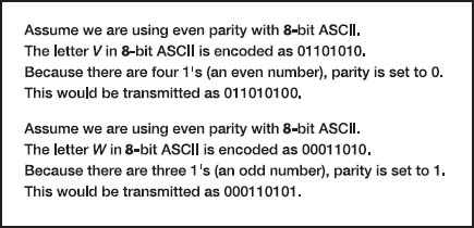
FIGURE 4.3 Using parity for error detection
Checksum With the checksum technique, a checksum (typically one byte) is added to the end of the message. The checksum is calculated by adding the decimal value of each character in the message, dividing the sum by 255, and using the remainder as the checksum. The receiver calculates its own checksum in the same way and compares it with the transmitted checksum. If the two values are equal, the message is presumed to contain no errors. Use of checksum detects close to 95 percent of the errors for multiple-bit burst errors.
Cyclical Redundancy Check One of the most popular error-checking schemes is cyclical redundancy check (CRC). It adds 8, 16, 24, or 32 bits to the message. With CRC, a message is treated as one long binary number, P. Before transmission, the data link layer (or hardware device) divides P by a fixed binary number, G, resulting in a whole number, Q, and a remainder, R/G. So, P/G = Q +R/G. For example, if P = 58 and G = 8, then Q = 7 and R = 2. G is chosen so that the remainder, R, will be either 8 bits, 16 bits, 24 bits, or 32 bits.1
The remainder, R, is appended to the message as the error-checking characters before transmission. The receiving hardware divides the received message by the same G, which generates an R. The receiving hardware checks to ascertain whether the received R agrees with the locally generated R. If it does not, the message is assumed to be in error.
Cyclical redundancy check performs quite well. The most commonly used CRC codes are CRC-16 (a 16-bit version), CRC-CCITT (another 16-bit version), and CRC-32 (a 32-bit version). The probability of detecting an error is 100% for all errors of the same length as the CRC or less. For example, CRC-16 is guaranteed to detect errors if 16 or fewer bits are affected. If the burst error is longer than the CRC, then CRC is not perfect but is close to it. CRC-16 will detect about 99.998 percent of all burst errors longer than 16 bits, whereas CRC-32 will detect about 99.99999998 percent of all burst errors longer than 32 bits.
4.3.4 Error Correction via Retransmission
Once error has been detected, it must be corrected. The simplest, most effective, least expensive, and most commonly used method for error correction is retransmission. With retransmission, a receiver that detects an error simply asks the sender to retransmit the message until it is received without error. This is often called Automatic Repeat reQuest (ARQ). There are two types of ARQ: stop-and-wait and continuous.
Stop-and-Wait ARQ With stop-and-wait ARQ, the sender stops and waits for a response from the receiver after each data packet. After receiving a packet, the receiver sends either an acknowledgment (ACK), if the packet was received without error, or a negative acknowledgment (NAK), if the message contained an error. If it is an NAK, the sender resends the previous message. If it is an ACK, the sender continues with the next message. Stop-and-wait ARQ is by definition a half-duplex transmission technique (Figure 4.4).
Continuous ARQ With continuous ARQ, the sender does not wait for an acknowledgment after sending a message; it immediately sends the next one. Although the messages are being transmitted, the sender examines the stream of returning acknowledgments. If it receives an NAK, the sender retransmits the needed messages. The packets that are retransmitted may be only those containing an error (called Link Access Protocol for Modems [LAP-M]) or may be the first packet with an error and all those that followed it (called Go-Back-N ARQ). LAP-M is better because it is more efficient.
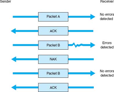
FIGURE 4.4 Stop-and-wait ARQ (Automatic Repeat reQuest). ACK = acknowledgment; NAK = negative acknowledgment
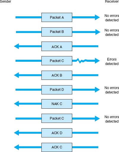
FIGURE 4.5 Continuous ARQ (Automatic Repeat reQuest). ACK = acknowledgment; NAK = negative acknowledgment
Continuous ARQ is by definition a full-duplex transmission technique, because both the sender and the receiver are transmitting simultaneously. (The sender is sending messages, and the receiver is sending ACKs and NAKs.) Figure 4.5 illustrates the flow of messages on a communication circuit using continuous ARQ. Continuous ARQ is sometimes called sliding window because of the visual imagery the early network designers used to think about continuous ARQ. Visualize the sender having a set of messages to send in memory stacked in order from first to last. Now imagine a window that moves through the stack from first to last. As a message is sent, the window expands to cover it, meaning that the sender is waiting for an ACK for the message. As an ACK is received for a message, the window moves forward, dropping the message out of the bottom of the window, indicating that it has been sent and received successfully.
Continuous ARQ is also important in providing flow control, which means ensuring that the computer sending the message is not transmitting too quickly for the receiver. For example, if a client computer was sending information too quickly for a server computer to store a file being uploaded, the server might run out of memory to store the file. By using ACKs and NAKs, the receiver can control the rate at which it receives information. With stop-and-wait ARQ, the receiver does not send an ACK until it is ready to receive more packets. In continuous ARQ, the sender and receiver usually agree on the size of the sliding window. Once the sender has transmitted the maximum number of packets permitted in the sliding window, it cannot send any more packets until the receiver sends an ACK.
4.1 HOW FORWARD ERROR CORRECTION WORKS
TECHNICAL FOCUS
To see how error-correcting codes work, consider the example of a forward error checking code in Figure 4.6, called a Hamming code, after its inventor, R. W. Hamming. This code is a very simple approach, capable of correcting 1-bit errors. More sophisticated techniques (e.g., Reed–Solomon) are commonly used today, but this will give you a sense of how they work.
The Hamming code associates even parity bits with unique combinations of data bits. With a 4-data-bit code as an example, a character might be represented by the data-bit configuration 1010. Three parity bits, P1, P2, and P4, are added, resulting in a 7-bit code, shown in the upper half of Figure 4.6. Notice that the data bits (D3, D5, D6, D7) are 1010 and the parity bits (P1, P2, P4) are 101.
As depicted in the upper half of Figure 4.6, parity bit P1 applies to data bits D3, D5, and D7. Parity bit P2 applies to data bits D3, D6, and D7. Parity bit P4 applies to data bits D5, D6, and D7. For the example, in which D3, D5, D6, D7 = 1010, P1 must equal 1 because there is only a single 1 among D3, D5 and D7 and parity must be even. Similarly, P2 must be 0 because D3 and D6 are 1’s. P4 is 1 because D6 is the only 1 among D5, D6, and D7.
Now, assume that during the transmission, data bit D7 is changed from a 0 to a 1 by line noise. Because this data bit is being checked by P1, P2, and P4, all 3 parity bits now show odd parity instead of the correct even parity. D7 is the only data bit that is monitored by all 3 parity bits; therefore, when D7 is in error, all 3 parity bits show an incorrect parity. In this way, the receiving equipment can determine which bit was in error and reverse its state, thus correcting the error without retransmission.
The lower half of the figure is a table that determines the location of the bit in error. A 1 in the table means that the corresponding parity bit indicates a parity error. Conversely, a 0 means the parity check is correct. These 0’s and 1’s form a binary number that indicates the numeric location of the erroneous bit. In the previous example, P1, P2, and P4 checks all failed, yielding 111, or a decimal 7, the subscript of the erroneous bit.
4.3.5 Forward Error Correction
Forward error correction uses codes containing sufficient redundancy to prevent errors by detecting and correcting them at the receiving end without retransmission of the original message. The redundancy, or extra bits required, varies with different schemes. It ranges from a small percentage of extra bits to 100% redundancy, with the number of error-detecting bits roughly equaling the number of data bits. One of the characteristics of many error-correcting codes is that there must be a minimum number of error-free bits between bursts of errors.
Forward error correction is commonly used in satellite transmission. A round trip from the earth station to the satellite and back includes a significant delay. Error rates can fluctuate depending on the condition of equipment, sunspots, or the weather. Indeed, some weather conditions make it impossible to transmit without some errors, making forward error correction essential. Compared with satellite equipment costs, the additional cost of forward error correction is insignificant.
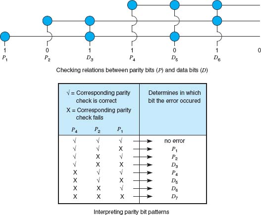
FIGURE 4.6 Hamming code for forward error correction
4.3.6 Error Control in Practice
In the OSI model (see Chapter 1), error control is defined to be a layer-2 function—it is the responsibility of the data link layer. However, in practice, we have moved away from this. Most network cables—especially LAN cables—are very reliable and errors are far less common than they were in the 1980s.
Therefore, most data link layer software used in LANs (i.e., Ethernet) is configured to detect errors, but not correct them. Any time a packet with an error is discovered, it is simply discarded. Wireless LANs and some WANs, where errors are more likely, still perform both error detection and error correction.
The implication from this is that error correction must be performed by software at higher layers. This software must be able to detect lost packets (i.e., those that have been discarded) and request the sender to retransmit them. This is commonly done by the transport layer using continuous ARQ as we shall see in the next chapter.
4.4 DATA LINK PROTOCOLS
In this section, we outline several commonly used data link layer protocols, which are summarized in Figure 4.7. Here we focus on message delineation, which indicates where a message starts and stops, and the various parts or fields within the message. For example, you must clearly indicate which part of a message or packet of data is the error-control portion; otherwise, the receiver cannot use it properly to determine if an error has occurred. The data link layer performs this function by adding a PDU to the packet it receives from the network layer. This PDU is called a frame.

4.4.1 Asynchronous Transmission
Asynchronous transmission is often referred to as start-stop transmission because the transmitting computer can transmit a character whenever it is convenient, and the receiving computer will accept that character. It is typically used on point-to-point full-duplex circuits (i.e., circuits that have only two computers on them), so media access control is not a concern. If you use VT100 protocol, or connect to a UNIX or Linux computer using Telnet, chances are you are using asynchronous transmission.
With asynchronous transmission, each character is transmitted independently of all other characters. To separate the characters and synchronize transmission, a start bit and a stop bit are put on the front and back of each individual character. For example, if we are using 7-bit ASCII with even parity, the total transmission is 10 bits for each character (1 start bit, 7 bits for the letter, 1 parity bit, 1 stop bit).
The start bit and stop bit are the opposite of each other. Typically, the start bit is a 0 and the stop bit is a 1. There is no fixed distance between characters because the terminal transmits the character as soon as it is typed, which varies with the speed of the typist. The recognition of the start and stop of each message (called synchronization) takes place for each individual character because the start bit is a signal that tells the receiver to start sampling the incoming bits of a character so the data bits can be interpreted into their proper character structure. A stop bit informs the receiver that the character has been received and resets it for recognition of the next start bit.
When the sender is waiting for the user to type the next character, no data are sent; the communication circuit is idle. This idle time really is artificial—some signal always must be sent down the circuit. For example, suppose we are using a unipolar digital signaling technique where +5 volts indicates a 1 and 0 volts indicates a 0 (see Chapter 3). Even if we send 0 volts, we are still sending a signal, a 0 in this case. Asynchronous transmission defines the idle signal (the signal that is sent down the circuit when no data are being transmitted) as the same as the stop bit. When the sender finishes transmitting a letter and is waiting for more data to send, it sends a continuous series of stop bits. Figure 4.8 shows an example of asynchronous transmission.
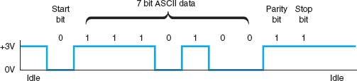
FIGURE 4.8 Asynchronous transmission. ASCII = United States of America Standard Code for Information Interchange
Some older protocols have two stop bits instead of the traditional single stop bit. The use of both a start bit and a stop bit is changing; some protocols have eliminated the stop bit altogether.
4.4.2 Synchronous Transmission
With synchronous transmission, all the letters or data in one group of data are transmitted at one time as a block of data. This block of data is called a frame. For example, a terminal or personal computer will save all the keystrokes typed by the user and transmit them only when the user presses a special “transmit” key. In this case, the start and end of the entire frame must be marked, not the start and end of each letter. Synchronous transmission is often used on both point-to-point and multipoint circuits. For multipoint circuits, each packet must include a destination address and a source address, and media access control is important.
The start and end of each frame (synchronization) sometimes is established by adding synchronization characters (SYN) to the start of the frame. Depending on the protocol, there may be anywhere from one to eight SYN characters. After the SYN characters, the transmitting computer sends a long stream of data that may contain thousands of bits. Knowing what code is being used, the receiving computer counts off the appropriate number of bits for the first character, assumes this is the first character, and passes it to the computer. It then counts off the bits for the second character, and so on.
In summary, asynchronous data transmission means each character is transmitted as a totally independent entity with its own start and stop bits to inform the receiving computer that the character is beginning and ending. Synchronous transmission means whole blocks of data are transmitted as frames after the sender and the receiver have been synchronized.
There are many protocols for synchronous transmission. We discuss four commonly used synchronous data link protocols.
Synchronous Data Link Control Synchronous data link control (SDLC) is a mainframe protocol developed by IBM in 1972 that is still in use today. It uses a controlled-access media access protocol. If you use a 3270 protocol, you're using SDLC.
Figure 4.9 shows a typical SDLC frame. Each SDLC frame begins and ends with a special bit pattern (01111110), known as the flag. The address field identifies the destination. The length of the address field is usually 8 bits but can be set at 16 bits; all computers on the same network must use the same length. The control field identifies the kind of frame that is being transmitted, either information or supervisory. An information frame is used for the transfer and reception of messages, frame numbering of contiguous frames, and the like. A supervisory frame is used to transmit acknowledgments (ACKs and NAKs). The message field is of variable length and is the user's message. The frame check sequence field is a 32-bit CRC code (some older versions use a 16-bit CRC).

FIGURE 4.9 SDLC (synchronous data link control) frame layout
High-Level Data Link Control High-level data link control (HDLC) is a formal standard developed by the ISO often used in WANs. HDLC is essentially the same as SDLC, except that the address and control fields can be longer. HDLC also has several additional benefits that are beyond the scope of this book, such as a larger sliding window for continuous ARQ. It uses a controlled-access media access protocol. One variant, Link Access Protocol–Balanced (LAP-B), uses the same structure as HDLC but is a scaled-down version of HDLC (i.e., provides fewer of those benefits mentioned that are “beyond the scope of this book”). A version of HDLC called Cisco HDLC (cHDLC) includes a network protocol field. cHDLC and HDLC have gradually replaced SDLC.
Ethernet Ethernet is a very popular LAN protocol, conceived by Bob Metcalfe in 1973 and developed jointly by Digital, Intel, and Xerox in the 1970s. Since then, Ethernet has been further refined and developed into a formal standard called IEEE 802.3 ac. There are several versions of Ethernet in use today. Ethernet uses a contention media access protocol.
There are several standard versions of Ethernet. Figure 4.10a shows an Ethernet 803.3ac frame. The frame starts with a 7-byte preamble which is a repeating pattern of ones and zeros (10101010). This is followed by a start of frame delimiter, which marks the start of the frame. The destination address specifies the receiver, whereas the source address specifies the sender. The length indicates the length in 8-bit bytes of the message portion of the frame. The VLAN tag field is an optional 4-byte address field used by virtual LANs (VLANs), which are discussed in Chapter 7. The Ethernet frame uses this field only when VLANs are in use; otherwise the field is omitted, and the length field immediately follows the source address field. When the VLAN tag field is in use, the first two bytes are set to the number 24,832 (hexadecimal 81-00), which is obviously an impossible packet length. When Ethernet sees this length, it knows that the VLAN tag field is in use. When the length is some other value, it assumes that VLAN tags are not in use and that the length field immediately follows the source address field. The DSAP and SSAP are used to pass control information between the sender and receiver. These are often used to indicate the type of network layer protocol the packet contains (e.g., TCP/IP or IPX/SPX, as described in Chapter 5). The control field is used to hold the frame sequence numbers and ACKs and NAKs used for error control, as well as to enable the data link layers of communicating computers to exchange other control information. The last 2 bits in the first byte are used to indicate the type of control information being passed and whether the control field is 1 or 2 bytes (e.g., if the last 2 bits of the control field are 11, then the control field is 1 byte in length). In most cases, the control field is 1-byte long. The maximum length of the message is about 1,500 bytes. The frame ends with a CRC-32frame check sequence used for error detection.

FIGURE 4.10a Ethernet 802.3ac frame layout

FIGURE 4.10b Ethernet II frame layout
Ethernet II is another commonly used version of Ethernet. Like SDLC, it uses a preamble to mark the start of the frame. It has the same source and destination address format as Ethernet 802.3ac. The type field is used to specify an ACK frame or the type of network layer packet the frame contains (e.g., IP). The data and frame check sequence fields are the same as Ethernet 802.3ac. Ethernet II has an unusual way of marking the end of a frame. It uses bipolar signaling to send 1’s (positive voltage) and 0’s (negative voltage); see Chapter 3. When the frame ends, the sending computer transmits no signal for 96-bits (i.e., neither a 0 or a 1). After these 96-bits have been on no signal, the sending computer then transmits the next frame, which starts with a preamble and so on. It is possible that in the time that the computer is sending no signal some other computer could jump in and begin transmitting. In fact, this 96-bit pause is designed to prevent any one computer from monopolizing the circuit.
Newer versions of these two types of Ethernet permits jumbo frames with up to 9,000 bytes of user data in the message field. Some vendors are experimenting with super jumbo frames that can hold up to 64,000 bytes. Jumbo frames are common for some types of Ethernet such as gigabit Ethernet (see Chapter 6).
Point-to-Point Protocol Point-to-Point Protocol (PPP) was developed in the early 1990s and is often used in WANs. It is designed to transfer data over a point-to-point circuit but provides an address so that it can be used on multipoint circuits. Figure 4.11 shows the basic layout of a PPP frame, which is very similar to an SDLC or HDLC frame. The frame starts with a flag, and has a one-byte address (which is not used on point-to-point circuits). The control field is typically not used. The protocol field indicates what type of data packet the frame contains (e.g., an IP packet). The data field is variable in length and may be up to 1,500 bytes. The frame check sequence is usually a CRC-16, but can be a CRC-32. The frame ends with a flag.

A Day in the Life: Network Support Technician
When a help call arrives at the help desk, the help desk staff (first-level support) spends up to 10 minutes attempting to solve the problem. If they can't, then the problem is passed to the second-level support, the network support technician.
A typical day in the life of a network support technician starts by working on computers from the day before. Troubleshooting usually begins with a series of diagnostic tests to eliminate hardware problems. The next step, for a laptop, is to remove the hard disk and replace it with a hard disk containing a correct standard image. If the computer passes those tests then the problem is usually software. Then the fun begins.
Once a computer has been fixed it is important to document all the hardware and/or software changes to help track problem computers or problem software. Sometimes a problem is new but relatively straightforward to correct once it has been diagnosed. In this case, the technician will change the standard support process followed by the technicians working at the help desk to catch the problem before it is escalated to the network support technicians. In other cases, a new entry is made into the organization's technical support knowledge base so that if another technician (or user) encounters the problem it is easier for him or her to diagnose and correct the problem. About 10% of the time the network technician is spent documenting solutions to problems.
Network support technicians also are the ones who manage new inventory and set up and configure new computers as they arrive from the manufacturer. In addition, they are responsible for deploying new software and standard desktop images across the network. Many companies also set aside standard times for routine training; in our case, every Friday, several hours is devoted to regular training.
With thanks to Doug Strough
4.5 TRANSMISSION EFFICIENCY
One objective of a data communication network is to move the highest possible volume of accurate information through the network. The higher the volume, the greater the resulting network's efficiency and the lower the cost. Network efficiency is affected by characteristics of the circuits such as error rates and maximum transmission speed, as well as by the speed of transmitting and receiving equipment, the error-detection and control methodology, and the protocol used by the data link layer.
Each protocol we discussed uses some bits or bytes to delineate the start and end of each message and to control error. These bits and bytes are necessary for the transmission to occur, but they are not part of the message. They add no value to the user, but they count against the total number of bits that can be transmitted.
Each communication protocol has both information bits and overhead bits. Information bits are those used to convey the user's meaning. Overhead bits are used for purposes such as error checking and marking the start and end of characters and packets. A parity bit used for error checking is an overhead bit because it is not used to send the user's data; if you did not care about errors, the overhead error checking bit could be omitted and the users could still understand the message.
Transmission efficiency is defined as the total number of information bits (i.e., bits in the message sent by the user) divided by the total bits in transmission (i.e., information bits plus overhead bits). For example, let's calculate the transmission efficiency of asynchronous transmission. Assume we are using 7-bit ASCII. We have 1 bit for parity, plus 1 start bit and 1 stop bit. Therefore, there are 7 bits of information in each letter, but the total bits per letter is 10 (7 + 3). The efficiency of the asynchronous transmission system is 7 bits of information divided by 10 total bits, or 70%.
In other words, with asynchronous transmission, only 70% of the data rate is available for the user; 30% is used by the transmission protocol. If we have a communication circuit using a dial-up modem receiving 56 Kbps, the user sees an effective data rate (or throughput) of 39.2 Kbps. This is very inefficient.
We can improve efficiency by reducing the number of overhead bits in each message or by increasing the number of information bits. For example, if we remove the stop bits from asynchronous transmission, efficiency increases to 7/9, or 77.8%. The throughput of a dial-up modem at 56 Kbps would increase 43.6 Kbps, which is not great but is at least a little better.
The same basic formula can be used to calculate the efficiency of synchronous transmission. For example, suppose we are using SDLC. The number of information bits is calculated by determining how many information characters are in the message. If the message portion of the frame contains 100 information characters and we are using an 8-bit code, then there are 100 × 8 = 800 bits of information. The total number of bits is the 800 information bits plus the overhead bits that are inserted for delineation and error control. Figure 4.9 shows that SDLC has a beginning flag (8 bits), an address (8 bits), a control field (8 bits), a frame check sequence (assume we use a CRC-32 with 32 bits), and an ending flag (8 bits). This is a total of 64 overhead bits; thus, efficiency is 800/(800 + 64) = 92.6%. If the circuit provides a data rate of 56 Kbps, then the effective data rate available to the user is about 51.9 Kbps.
This example shows that synchronous networks usually are more efficient than asynchronous networks and some protocols are more efficient than others. The longer the message (1,000 characters as opposed to 100), the more efficient the protocol. For example, suppose the message in the SDLC example were 1,000 bytes. The efficiency here would be 99.2%, or 8,000/(8000 + 64), giving an effective data rate of about 55.6 Kbps.
The general rule is that the larger the message field, the more efficient the protocol. So why not have 10,000-byte or even 100,000-byte packets to really increase efficiency? The answer is that anytime a frame is received containing an error, the entire frame must be retransmitted. Thus, if an entire file is sent as one large packet (e.g., 100K) and 1 bit is received in error, all 100,000 bytes must be sent again. Clearly, this is a waste of capacity. Furthermore, the probability that a frame contains an error increases with the size of the frame; larger frames are more likely to contain errors than are smaller ones, simply due to the laws of probability.
Thus, in designing a protocol, there is a trade-off between large and small frames. Small frames are less efficient but are less likely to contain errors and cost less (in terms of circuit capacity) to retransmit if there is an error (Figure 4.12).
Throughput is the total number of information bits received per second, after taking into account the overhead bits and the need to retransmit frames containing errors. Generally speaking, small frames provide better throughput for circuits with more errors, whereas larger frames provide better throughput in less-error-prone networks. Fortunately, in most real networks, the curve shown in Figure 4.12 is very flat on top, meaning that there is a range of frame sizes that provide almost optimum performance. Frame sizes vary greatly among different networks, but the ideal frame size tends to be between 2,000 and 10,000 bytes.

FIGURE 4.12 Frame size effects on throughput
So why are the standard sizes of Ethernet frames about 1,500 bytes? Because Ethernet was standardized many years ago when errors were more common. Jumbo and super jumbo frame sizes emerged from higher speed, highly error free fiber-optic networks.
4.2 SLEUTHING FOR THE RIGHT FRAME SIZE
MANAGEMENT FOCUS
Optimizing performance in a network, particularly a client–server network, can be difficult because few network managers realize the importance of the frame size. Selecting the right—or the wrong—frame size can have greater effects on performance than anything you might do to the server.
Standard Commercial, a multinational tobacco and agricultural company, noticed a decrease in network performance when they upgraded to a new server. They tested the effects of using frame sizes between 500 bytes to 32,000 bytes. In their tests, a frame size of 512 bytes required a total of 455,000 bytes transmitted over their network to transfer the test messages. In contrast, the 32,000-byte frames were far more efficient, cutting the total data by 44 percent to 257,000 bytes.
However, the problem with 32,000-byte frames was a noticeable response time delay because messages were saved until the 32,000-byte frames were full before transmitting.
The ideal frame size depends on the specific application and the pattern of messages it generates. For Standard Commercial, the ideal frame size appeared to be between 4,000 and 8,000. Unfortunately, not all network software packages enable network managers to fine-tune frame sizes in this way.
__________
SOURCE: “Sleuthing for the Right Packet Size,” InfoWorld, January 16, 1995.
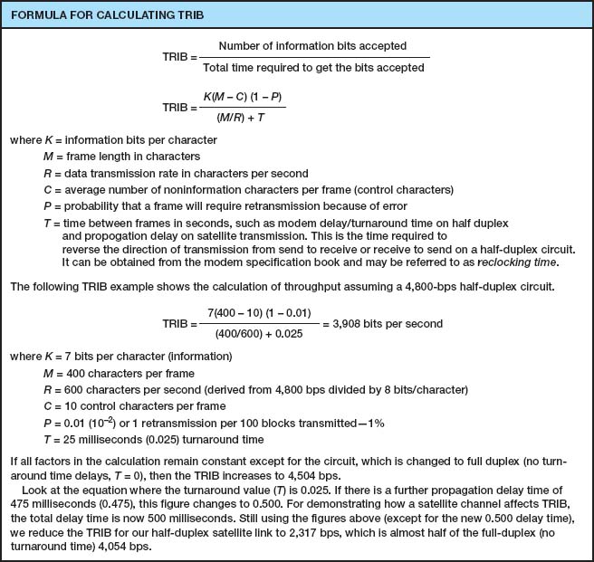
FIGURE 4.13 Calculating TRIB (transmission rate of information bits)
Calculating the actual throughput of a data communications network is complex because it depends not only on the efficiency of the data link protocol but also on the error rate and number of retransmissions that occur. Transmission rate of information bits (TRIB) is a measure of the effective number of information bits that is transmitted over a communication circuit per unit of time. The basic TRIB equation from ANSI is shown in Figure 4.13, along with an example.
4.6 IMPLICATIONS FOR MANAGEMENT
You can think of the data link layer protocol as the fundamental “language” spoken by networks. This protocol must be compatible with the physical cables that are used, but in many cases the physical cables can support a variety of different protocols. Each device on the network speaks a particular data link layer protocol. In the past, there were literally dozens of protocols that were used; each protocol was custom-tailored to specific needs of the devices and application software in use. Where different devices or cables from different parts of the organization were connected, we used a translator to convert from the data link protocol spoken by one device into the protocol spoken by another device.
As the Internet has become more prominent and as it has become more important to move data from one part of an organization to the other, the need to translate among different data link layer protocols has become more and more costly. It is now more important to provide a few widely used protocols for all networks than to custom tailor protocols to the needs of specific devices or applications. Today, businesses are moving rapidly to reduce the number of different protocols spoken by their networking equipment and converge on a few standard protocols that are used widely throughout the network.
We still do use different protocols in different parts of the network where there are important reasons for doing so. For example, local area networks often have different needs than wide area networks, so their data link layer protocols typically are still different, but even here we are seeing a few organizations move to standardize protocols.
This move to standardize data link layer protocols means that networking equipment and networking staff need to understand fewer protocols—their job is becoming simpler, which in turn means that the cost to buy and maintain network equipment and to train networking staff is gradually decreasing (and the side benefit to students is that there are fewer protocols to learn!). The downside, of course, is that some applications may take longer to run over protocols are not perfectly suited to them. As network capacities in the physical layer continue to increase, this has proven to be far less important than the significant cost savings that can be realized from standardization.
SUMMARY
Media Access Control Media access control refers to controlling when computers transmit. There are three basic approaches. With roll-call polling, the server polls client computers to see if they have data to send; computers can transmit only when they have been polled. With hub polling or token passing, the computers themselves manage when they can transmit by passing a token to one other; no computer can transmit unless it has the token. With contention, computers listen and transmit only when no others are transmitting. In general, contention approaches work better for small networks that have low levels of usage, whereas polling approaches work better for networks with high usage.
Sources and Prevention of Error Errors occur in all networks. Errors tend to occur in groups (or bursts) rather than 1 bit at a time. The primary sources of errors are impulse noises (e.g., lightning), cross-talk, echo, and attenuation. Errors can be prevented (or at least reduced) by shielding the cables; moving cables away from sources of noise and power sources; using repeaters (and, to a lesser extent, amplifiers); and improving the quality of the equipment, media, and their connections.
Error Detection and Correction All error-detection schemes attach additional error-detection data, based on a mathematical calculation, to the user's message. The receiver performs the same calculation on incoming messages, and if the results of this calculation do not match the error-detection data on the incoming message, an error has occurred. Parity, checksum, and CRC are the most common error-detection schemes. The most common error-correction technique is simply to ask the sender to retransmit the message until it is received without error. A different approach, forward error correction, includes sufficient information to allow the receiver to correct the error in most cases without asking for a retransmission.
Message Delineation Message delineation means to indicate the start and end of a message. Asynchronous transmission uses start and stop bits on each letter to mark where they begin and end. Synchronous techniques (e.g., SDLC, HDLC, Ethernet, PPP) group blocks of data together into frames that use special characters or bit patterns to mark the start and end of entire messages.
Transmission Efficiency and Throughput Every protocol adds additional bits to the user's message before sending it (e.g., for error detection). These bits are called overhead bits because they add no value to the user; they simply ensure correct data transfer. The efficiency of a transmission protocol is the number of information bits sent by the user divided by the total number of bits transferred (information bits plus overhead bits). Synchronous transmission provides greater efficiency than does asynchronous transmission. In general, protocols with larger frame sizes provide greater efficiency than do those with small frame sizes. The drawback to large frame sizes is that they are more likely to be affected by errors and thus require more retransmission. Small frame sizes are therefore better suited to error-prone circuits, and large frames, to error-free circuits.
KEY TERMS
access request
acknowledgment (ACK)
amplifier
asynchronous transmission
attenuation
Automatic Repeat reQuest (ARQ)
burst error
checksum
contention
continuous ARQ
controlled access
cross-talk
cyclical redundancy check (CRC)
echo
efficiency
error detection
error prevention
error rate
Ethernet (IEEE 802.3)
even parity
flow control
forward error correction
frame
Gaussian noise
Go-Back-N ARQ
Hamming code
high-level data link control (HDLC)
hub polling
impulse noise
information bits
intermodulation noise
line noise
Link Access Protocol-Balanced (LAP-B)
Link Access Protocol for Modems (LAP-M)
logical link control (LLC) sublayer
media access control
media access control (MAC) sublayer
negative acknowledgment (NAK)
odd parity
overhead bits
parity bit
parity check
Point-to-Point Protocol (PPP)
polling
repeater
roll-call polling
sliding window
start bit
stop-and-wait ARQ
stop bit
synchronization
synchronous transmission
throughput
token passing
transmission efficiency
white noise
QUESTIONS
- What does the data link layer do?
- What is media access control, and why is it important?
- Under what conditions is media access control unimportant?
- Compare and contrast roll-call polling, hub polling (or token passing), and contention.
- Which is better, controlled access or contention? Explain.
- Define two fundamental types of errors.
- Errors normally appear in _____, which is when more than 1 data bit is changed by the error-causing condition.
- Is there any difference in the error rates of lower-speed lines and higher-speed lines?
- Briefly define noise.
- Describe four types of noise. Which is likely to pose the greatest problem to network managers?
- How do amplifiers differ from repeaters?
- What are three ways of reducing errors and the types of noise they affect?
- Describe three approaches to detecting errors, including how they work, the probability of detecting an error, and any other benefits or limitations.
- Briefly describe how even parity and odd parity work.
- Briefly describe how checksum works.
- How does CRC work?
- How does forward error correction work? How is it different from other error-correction methods?
- Under what circumstances is forward error correction desirable?
- Compare and contrast stop-and-wait ARQ and continuous ARQ.
- Which is the simplest (least sophisticated) protocol described in this chapter?
- Describe the frame layouts for SDLC, Ethernet, and PPP.
- What is transmission efficiency?
- How do information bits differ from overhead bits?
- Are stop bits necessary in asynchronous transmission? Explain by using a diagram.
- During the 1990s, there was intense competition between two technologies (10-Mbps Ethernet and 16-Mbps token ring) for the LAN market. Ethernet was promoted by a consortium of vendors, whereas token ring was primarily an IBM product, even though it was standardized. Ethernet won, and no one talks about token ring anymore. Token ring used a hub-polling–based approach. Outline a number of reasons why Ethernet might have won. Hint: The reasons were both technical and business.
- Under what conditions does a data link layer protocol need an address?
- Are large frame sizes better than small frame sizes? Explain.
- What media access control technique does your class use?
- Show how the word “HI” would be sent using asynchronous transmission using even parity (make assumptions about the bit patterns needed). Show how it would be sent using Ethernet.
EXERCISES
4-1. Draw how a series of four separate messages would be successfully sent from one computer to another if the first message was transferred without error, the second was initially transmitted with an error, the third was initially lost, and the ACK for the fourth was initially lost.
4-2. How efficient would a 6-bit code be in asynchronous transmission if it had 1 parity bit, 1 start bit, and 2 stop bits? (Some old equipment uses 2 stop bits.)
4-3. What is the transmission rate of information bits if you use ASCII (8 bits plus 1 parity bit), a 1,000-character frame, 56 Kbps modem transmission speed, 20 control characters per frame, an error rate of 1%, and a 30-millisecond turnaround time? What is the TRIB if you add a half-second delay to the turnaround time because of satellite delay?
4-4. Search the Web to find a software vendor that sells a package that supports each of the following protocols: SDLC, HDLC, Ethernet, and PPP (i.e., one package that supports SDLC, another [or the same] for HDLC and so on).
4-5. Investigate the network at your organization (or a service offered by an IXC) to find out the average error rates.
4-6. What is the efficiency if a 100-byte file is transmitted using Ethernet? A 10,000-byte file?
4-7. What is the propagation delay on a circuit using a LEO satellite orbiting 500 miles above the earth if the speed of the signal is 186,000 miles per second? If the satellite is 22,000 miles above the earth?
4-8. Suppose you are going to connect the computers in your house or apartment. What media would you use? Why? Would this change if you were building a new house?
MINI-CASES
I. Smith, Smith, Smith, and Smith
Smith, Smith, Smith, and Smith is a regional accounting firm that is putting up a new headquarters building. The building will have a backbone network that connects eight LANs (two on each floor). The company is very concerned with network errors. What advice would you give regarding the design of the building and network cable planning that would help reduce network errors?
II. Worldwide Charity
Worldwide Charity is a charitable organization whose mission is to improve education levels in developing countries. In each country where it is involved, the organization has a small headquarters and usually five to ten offices in outlying towns. Staff members communicate with one another via email on older computers donated to the organization. Because Internet service is not reliable in many of the towns in these countries, the staff members usually phone headquarters and use a very simple Linux email system that uses a server-based network architecture. They also upload and download files. What range of frame sizes is likely to be used?
III. Industrial Products
Industrial Products is a small light-manufacturing firm that produces a variety of control systems for heavy industry. It has a network that connects its office building and warehouse that has functioned well for the last year, but over the past week, users have begun to complain that the network is slow. Clarence Hung, the network manager, did a quick check of the number of orders over the past week and saw no real change, suggesting that there has been no major increase in network traffic. What would you suggest that Clarence do next?
IV. Alpha Corp
Alpha Corp. is trying to decide the size of the connection it needs to the Internet. The company estimates that it will send and receive a total of about 1,000 emails per hour and that each email message is about 1,500 bytes in size. The company also estimates that it will send and receive a total of about 3,000 Web pages per hour and that each page is about 40,000 bytes in size. 1. Without considering transmission efficiency, how large an Internet connection would you recommend in terms of bits per second (assuming that each byte is eight bits in length)? 2. Assuming they use a synchronous data link layer protocol with an efficiency of about 90%, how large an Internet connection would you recommend? 3. Suppose Alpha wants to be sure that its Internet connection will provide sufficient capacity the next two years. How large an Internet connection would you recommend?
HANDS-ON ACTIVITY 4A
Capturing Packets on Your Network
In this chapter, we discussed several data link layer protocols, such as SDLC and Ethernet. The objective of this Activity is for you to see the data link layer frames in action on your network.
Wireshark is one of the many tools that permit users to examine the frames in their network. It is called a packet sniffer because it enables you to see inside the frames and packets that your computer sends, as well as the frames and packets sent by other users on your LAN. In other words, you can eavesdrop on the other users on your LAN to see what Web sites they visit and even the email they send. We don't recommend using it for this reason, but it is important that you understand that someone else could be using Ethereal to sniff your packets to see and record what you are doing on the Internet.
- Use your browser to connect to www.wireshark.org and download and install the Wireshark software.
- When you start Wireshark you will see a screen like that in Figure 4.14, minus the two smaller windows on top.
- Click Capture
- Click Interfaces
- Click the Capture button beside your Wire-shark connection (wireless LAN or traditional LAN).
- Wireshark will capture all packets moving through your LAN. To make sure you have something to see, open your Web browser and visit one or two Web sites. After you have captured packets for 30–60 seconds, return to Wireshark and click Stop.
- Figure 4.15 shows the packets captured on my home network. The top window in Wireshark displays the complete list of packets in chronological order. Each packet is numbered; I've scrolled the window, so the first packet shown is packet 11. Wireshark lists the time, the source IP address, the destination IP address, the protocol, and some additional information about each packet. The IP addresses will be explained in more detail in the next chapter.
For the moment, look at packet number 16, the second HTTP packet from the top. I've clicked on this packet, so the middle window shows the inside of the packet. The first line in this second window says the frame (or packet if you prefer) is 1091 bytes long. It contains an Ethernet II packet, an Internet Protocol (IP) packet, a Transmission Control Protocol (TCP) Packet, and a Hypertext Transfer Protocol (HTTP) packet. Remember in Chapter 1 that Figure 1.4 described how each packet was placed inside another packet as the message moved through the layers and was transmitted.
Click on the plus sign (+) in front of the HTTP packet to expand it. Wireshark shows the contents of the HTTP packet. By reading the data inside the HTTP packet, you can see that this packet was an HTTP request to my.yahoo.com that contained a cookie. If you look closely, you'll see that the sending computer was a Tablet PC—that's some of the optional information my Web browser (Internet Explorer) included in the HTTP header.

FIGURE 4.14 Capturing packets with Wireshark
The bottom window in Figure 4.15 shows the exact bytes that were captured. The section highlighted in grey shows the HTTP packet. The numbers on the left show the data in hexadecimal format while the data on the right show the text version. The data before the highlighted section is the TCP packet.
From Chapter 2, you know that the client sends an HTTP request packet to request a Web page, and the Web server sends back an HTTP response packet. Packet number 25 in the top window in Figure 4.15 is the HTTP response sent back to my computer by the Yahoo server. You can see that the destination IP address in my HTTP request is the source IP address of this HTTP packet.
- Figure 4.15 also shows what happens when you click the plus sign (+) in front of the Ethernet II packet to expand it. You can see that this Ethernet packet has a destination address and source address (e.g., 00:02:2d:85:cb:e0).
Deliverables
- List the layer 2, 3, 4, and 5 PDUs that are used in your network to send a request to get a Web page.
- List the source and destination Ethernet addresses on the message.
- What value is in the Ethernet type field in this message? Why?
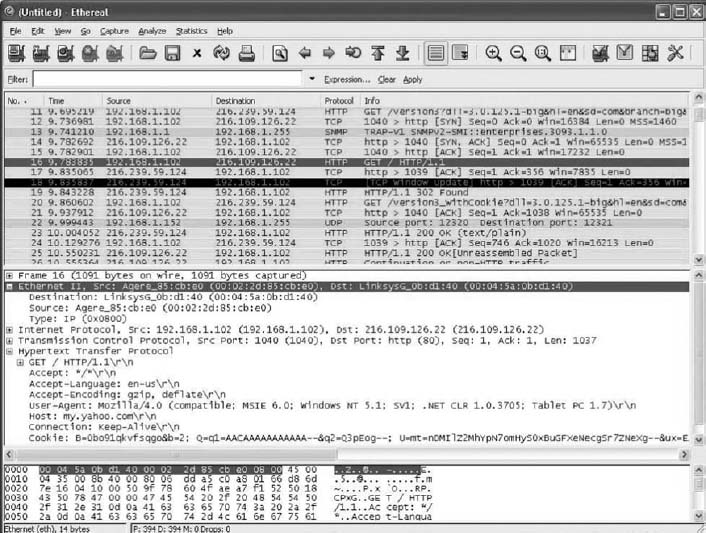
FIGURE 4.15 Analyzing packets with Wireshark
1 CRC is actually more complicated than this because it uses polynominal division, not “normal” division as illustrated here. Ross Willams provides an excellent tutorial on CRC at www.ross.net/crc/crcpaper.html.