CHAPTER 3
PHYSICAL LAYER

THE PHYSICAL layer (also called layer 1) is the physical connection between the computers and/or devices in the network. This chapter examines how the physical layer operates. It describes the most commonly used media for network circuits and explains the basic technical concepts of how data is actually transmitted through the media. Three different types of transmission are described: digital transmission of digital computer data; analog transmission of digital computer data; and digital transmission of analog voice data. You do not need an engineering-level understanding of the topics to be an effective user and manager of data communication applications. It is important, however, that you understand the basic concepts, so this chapter is somewhat technical.
OBJECTIVES ![]()
- Be familiar with the different types of network circuits and media
- Understand digital transmission of digital data
- Understand analog transmission of digital data
- Understand digital transmission of analog data
- Be familiar with analog and digital modems
- Be familiar with multiplexing
CHAPTER OUTLINE ![]()
3.4 DIGITAL TRANSMISSION OF DIGITAL DATA
3.4.4 How Ethernet Transmits Data
3.5 ANALOG TRANSMISSION OF DIGITAL DATA
3.5.3 How Modems Transmit Data
3.6 DIGITAL TRANSMISSION OF ANALOG DATA
3.6.1 Translating from Analog to Digital
3.6.2 How Telephones Transmit Voice Data
3.6.3 How Instant Messenger Transmits Voice Data
3.6.4 Voice over Internet Protocol (VoIP)
3.7 IMPLICATIONS FOR MANAGEMENT
3.1 INTRODUCTION
This chapter examines how the physical layer operates. The physical layer is the network hardware including servers, clients, and circuits, but in this chapter we focus on the circuits and on how clients and servers transmit data through them. The circuits are usually a combination of both physical media (e.g., cables, wireless transmissions) and special-purpose devices that enable the transmissions to travel through the media. Special-purpose devices such as hubs, switches, and routers are discussed in Chapter 6 and 8.
The word circuit has two very different meanings in networking, and sometimes it is hard to understand which meaning is intended. Sometimes, we use the word circuit to refer to the physical circuit—the actual wire—used to connect two devices. In this case, we are referring to the physical media that carry the message we transmit, such as the twisted pair wire used to connect a computer to the LAN in an office. In other cases, we are referring to a logical circuit used to connect two devices, which refers to the transmission characteristics of the connection, such as when we say a company has a T1 connection into the Internet. In this case, T1 refers not to the physical media (i.e., what type of wire is used) but rather to how fast data can be sent through the connection.1 Often, each physical circuit is also a logical circuit, but as you will see in the section on multiplexing, sometimes it is possible to have one physical circuit—one wire—carry several separate logical circuits, or to have one logical circuit travel over several physical circuits.
There are two fundamentally different types of data that can flow through the circuit: digital and analog. Computers produce digital data that are binary, either on or off, 0 or 1. In contrast, telephones produce analog data whose electrical signals are shaped like the sound waves they transfer; they can take on any value in a wide range of possibilities, not just 0 or 1.
Data can be transmitted through a circuit in the same form they are produced. Most computers, for example, transmit their digital data through digital circuits to printers and other attached devices. Likewise, analog voice data can be transmitted through telephone networks in analog form. In general, networks designed primarily to transmit digital computer data tend to use digital transmission, and networks designed primarily to transmit analog voice data tend to use analog transmission (at least for some parts of the transmission).
Data can be converted from one form into the other for transmission over network circuits. For example, digital computer data can be transmitted over an analog telephone circuit by using a modem. A modem at the sender's computer translates the computer's digital data into analog data that can be transmitted through the voice communication circuits, and a second modem at the receiver's end translates the analog transmission back into digital data for use by the receiver's computer.
Likewise, it is possible to translate analog voice data into digital form for transmission over digital computer circuits using a device called a codec. Once again, there are two codecs, one at the sender's end and one at the receiver's end. Why bother to translate voice into digital? The answer is that digital transmission is “better” than analog transmission. Specifically, digital transmission offers five key benefits over analog transmission:
- Digital transmission produces fewer errors than analog transmission. Because the transmitted data is binary (only two distinct values), it is easier to detect and correct errors.
- Digital transmission permits higher maximum transmission rates. Fiber-optic cable, for example, is designed for digital transmission.
- Digital transmission is more efficient. It is possible to send more data through a given circuit using digital rather than analog transmission.
- Digital transmission is more secure because it is easier to encrypt.
- Finally, and most importantly, integrating voice, video, and data on the same circuit is far simpler with digital transmission.
For these reasons, most long-distance telephone circuits built by the telephone companies and other common carriers over the past decades use digital transmission. In the future, most transmissions (voice, data, and video) will be sent digitally.
Regardless of whether digital or analog transmission is used, transmission requires the sender and receiver to agree on two key parameters. First, they have to agree on the symbols that will be used: what pattern of electricity, light, or radio wave will be used to represent a 0 and a 1. Once these symbols are set, the sender and receiver have to agree on the symbol rate: How many symbols will be sent over the circuit per second? Analog and digital transmissions are different, but both require a commonly agreed on set of symbols, and a symbol rate.
In this chapter, we first describe the basic types of circuits and examine the different media used to build circuits. Then we explain how data are actually sent through these media using digital and analog transmission.
3.2 CIRCUITS
3.2.1 Circuit Configuration
Circuit configuration is the basic physical layout of the circuit. There are two fundamental circuit configurations: point-to-point and multipoint. In practice, most complex computer networks have many circuits, some of which are point-to-point and some of which are multipoint.
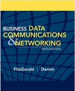
Figure 3.1 illustrates a point-to-point circuit, which is so named because it goes from one point to another (e.g., one computer to another computer). These circuits sometimes are called dedicated circuits because they are dedicated to the use of these two computers. This type of configuration is used when the computers generate enough data to fill the capacity of the communication circuit. When an organization builds a network using point-to-point circuits, each computer has its own circuit running from itself to the other computers. This can get very expensive, particularly if there is some distance between the computers.
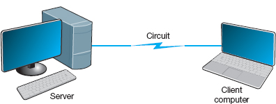
FIGURE 3.1 Point-to-point circuit
Figure 3.2 shows a multipoint circuit (also called a shared circuit). In this configuration, many computers are connected on the same circuit. This means that each must share the circuit with the others. The disadvantage is that only one computer can use the circuit at a time. When one computer is sending or receiving data, all others must wait. The advantage of multipoint circuits is that they reduce the amount of cable required and typically use the available communication circuit more efficiently. Imagine the number of circuits that would be required if the network in Figure 3.2 was designed with separate point-to-point circuits. For this reason, multipoint configurations are cheaper than point-to-point circuits. Thus, multipoint circuits typically are used when each computer does not need to continuously use the entire capacity of the circuit or when building point-to-point circuits is too expensive. Wireless circuits are almost always multipoint circuits because multiple computers use the same radio frequencies and must take turns transmitting.
3.2.2 Data Flow
Circuits can be designed to permit data to flow in one direction or in both directions. Actually, there are three ways to transmit: simplex, half-duplex, and full-duplex (Figure 3.3).
Simplex transmission is one-way transmission, such as that with radios and TVs.
Half-duplex transmission is two-way transmission, but you can transmit in only one direction at a time. A half-duplex communication link is similar to a walkie-talkie link; only one computer can transmit at a time. Computers use control signals to negotiate which will send and which will receive data. The amount of time half-duplex communication takes to switch between sending and receiving is called turnaround time (also called retrain time or reclocking time). The turnaround time for a specific circuit can be obtained from its technical specifications (often between 20 and 50 milliseconds). Europeans sometimes use the term simplex circuit to mean a half-duplex circuit.
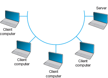

FIGURE 3.3 Simplex, half-duplex, and full-duplex transmissions
With full-duplex transmission, you can transmit in both directions simultaneously, with no turnaround time.
How do you choose which data flow method to use? Obviously, one factor is the application. If data always need to flow only in one direction (e.g., from a remote sensor to a host computer), then simplex is probably the best choice. In most cases, however, data must flow in both directions.
The initial temptation is to presume that a full-duplex channel is best; however, each circuit has only so much capacity to carry data. Creating a full-duplex circuit means that the available capacity in the circuit is divided—half in one direction and half in the other. In some cases, it makes more sense to build a set of simplex circuits in the same way a set of one-way streets can increase the speed of traffic. In other cases, a half-duplex circuit may work best. For example, terminals connected to mainframes often transmit data to the host, wait for a reply, transmit more data, and so on, in a turn-taking process; usually, traffic does not need to flow in both directions simultaneously. Such a traffic pattern is ideally suited to half-duplex circuits.
3.2.3 Multiplexing
Multiplexing means to break one high-speed physical communication circuit into several lower-speed logical circuits so that many different devices can simultaneously use it but still “think” that they have their own separate circuits (the multiplexer is “transparent”). It is multiplexing (specifically, wavelength division multiplexing [WDM], discussed later in this section) that has enabled the almost unbelievable growth in network capacity discussed in Chapter 1; without WDM, the Internet would have collapsed in the 1990s.
Multiplexing often is done in multiples of 4 (e.g., 8, 16). Figure 3.4 shows a four-level multiplexed circuit. Note that two multiplexers are needed for each circuit: one to combine the four original circuits into the one multiplexed circuit and one to separate them back into the four separate circuits.

FIGURE 3.4 Multiplexed circuit
The primary benefit of multiplexing is to save money by reducing the amount of cable or the number of network circuits that must be installed. For example, if we did not use multiplexers in Figure 3.4, we would need to run four separate circuits from the clients to the server. If the clients were located close to the server, this would be inexpensive. However, if they were located several miles away, the extra costs could be substantial.
There are four types of multiplexing: frequency division multiplexing (FDM), time division multiplexing (TDM), statistical time division multiplexing (STDM), and wavelength division multiplexing WDM.
Frequency Division Multiplexing Frequency division multiplexing (FDM) can be described as dividing the circuit “horizontally” so that many signals can travel a single communication circuit simultaneously. The circuit is divided into a series of separate channels, each transmitting on a different frequency, much like series of different radio or TV stations. All signals exist in the media at the same time, but because they are on different frequencies, they do not interfere with each other.
Figure 3.5 illustrates the use of FDM to divide one circuit into four channels. Each channel is a separate logical circuit, and the devices connected to them are unaware that their circuit is multiplexed. In the same way that radio stations must be assigned separate frequencies to prevent interference, so must the signals in a FDM circuit. The guardbands in Figure 3.5 are the unused portions of the circuit that separate these frequencies from each other.
With FDM, the total capacity of the physical circuit is simply divided among the multiplexed circuits. For example, suppose we had a physical circuit with a data rate of 64 Kbps that we wanted to divide into four circuits. We would simply divide the 64 Kbps among the four circuits and assign each circuit 16 Kbps. However, because FDM needs guardbands, we also have to allocate some of the capacity to the guardbands, so we might actually end up with four circuits, each providing 15 Kbps, with the remaining 4 Kbps allocated to the guardbands. There is no requirement that all circuits be the same size, as you will see in a later section. FDM was commonly used in older telephone systems, which is why the bandwidth on older phone systems was only 3,000 Hz, not the 4,000 Hz actually available—1,000 Hz were used as guardbands, with the voice signals traveling between two guardbands on the outside of the channel.

FIGURE 3.5 Frequency division multiplex (FDM) circuit
Time Division Multiplexing Time division multiplexing (TDM) shares a communication circuit among two or more computers by having them take turns, dividing the circuit vertically, so to speak. Figure 3.6 shows the same four computers connected using TDM. In this case, one character is taken from each computer in turn, transmitted down the circuit, and delivered to the appropriate device at the far end (e.g., one character from computer A, then one from B, one from C, one from D, another from A, another from B, and so on). Time on the circuit is allocated even when data are not being transmitted, so that some capacity is wasted when terminals are idle. TDM generally is more efficient than FDM because it does not need guardbands. Guardbands use “space” on the circuit that otherwise could be used to transmit data. Therefore, if one divides a 64-Kbps circuit into four circuits, the result would be four 16-Kbps circuits.
Statistical Time Division Multiplexing Statistical time division multiplexing (STDM) is the exception to the rule that the capacity of the multiplexed circuit must equal the sum of the circuits it combines. STDM allows more terminals or computers to be connected to a circuit than does FDM or TDM. If you have four computers connected to a multiplexer and each can transmit at 64 Kbps, then you should have a circuit capable of transmitting 256 Kbps (4 × 64 Kbps). However, not all computers will be transmitting continuously at their maximum transmission speed. Users typically pause to read their screens or spend time typing at lower speeds. Therefore, you do not need to provide a speed of 256 Kbps on this multiplexed circuit. If you assume that only two computers will ever transmit at the same time, 128 Kbps would be enough. STDM is called statistical because selection of transmission speed for the multiplexed circuit is based on a statistical analysis of the usage requirements of the circuits to be multiplexed.
FIGURE 3.6 Time division multiplex (TDM) circuit
The key benefit of STDM is that it provides more efficient use of the circuit and saves money. You can buy a lower-speed, less-expensive circuit than you could using FDM or TDM. STDM introduces two additional complexities. First, STDM can cause time delays. If all devices start transmitting or receiving at the same time (or just more than at the statistical assumptions), the multiplexed circuit cannot transmit all the data it receives because it does not have sufficient capacity. Therefore, STDM must have internal memory to store the incoming data that it cannot immediately transmit. When traffic is particularly heavy, you may have a 1- to 30-second delay. The second problem is that because the logical circuits are not permanently assigned to specific devices as they are in FDM and TDM, the data from one device are interspersed with data from other devices. The first message might be from the third computer, the second from the first computer, and so on. Therefore, we need to add some address information to each packet to make sure we can identify the logical circuit to which it belongs. This is not a major problem, but it does increase the complexity of the multiplexer and also slightly decreases efficiency, because now we must “waste” some of the circuit's capacity in transmitting the extra address we have added to each packet.
Wavelength Division Multiplexing Wavelength division multiplexing (WDM) is a version of FDM used in fiber-optic cables. When fiber-optic cables were first developed, the devices attached to them were designed to use only one color of light generated by a laser or LED. With one commonly used type of fiber cable, the data rate is 622 Mbps (622 million bits per second). At first, the 622-Mbps data rate seemed wonderful. Then the amount of data transferred over the Internet began doubling at fairly regular intervals, and several companies began investigating how we could increase the amount of data sent over existing fiber-optic cables.
The answer, in hindsight, was obvious. Light has different frequencies (i.e., colors), so rather than building devices to transmit using only one color, why not send multiple signals, each in a different frequency, through the same fiber cable? By simply attaching different devices that could transmit in the full spectrum of light rather than just one frequency, the capacity of the existing fiber-optic cables could be dramatically increased, with no change to the physical cables themselves.
Wavelength division multiplexing works by using lasers to transmit different frequencies of light (i.e., colors) through the same fiber-optic cable. As with FDM, each logical circuit is assigned a different frequency, and the devices attached to the circuit don't “know” they are multiplexed over the same physical circuit.
3.1 NASA'S GROUND COMMUNICATIONS NETWORK
MANAGEMENT FOCUS
NASA's communications network is extensive because its operations are spread out around the world and into space. The main Deep Space Network is controlled out of the Jet Propulsion Laboratory (JPL) in California. JPL is connected to the three main Deep Space Communications Centers (DSCCs) that communicate with NASA spacecraft. The three DSCCs are spread out equidistantly around the world so that one will always be able to communicate with spacecraft no matter where they are in relation to the earth: Canberra, Australia; Madrid, Spain; and Goldstone, California.
Figure 3.7 shows the JPL network. Each DSCC has four large-dish antennas ranging in size from 85 to 230 feet (26 to 70 meters) that communicate with the spacecraft. These send and receive operational data such as telemetry, commands, tracking, and radio signals. Each DSCC also sends and receives administrative data such as email, reports, and Web pages, as well as telephone calls and video.
The three DSCCs and JPL use Ethernet local area networks (LANs) that are connected to multiplexers that integrate the data, voice, and video signals for transmission. Satellite circuits are used between Canberra and JPL and Madrid and JPL. Fiber-optic circuits are used between JPL and Goldstone.
Dense WDM (DWDM) is a variant of WDM that further increases the capacity of WDM by adding TDM to WDM. DWDM permits up to 40 simultaneous circuits, each transmitting up to 10 Gbps, giving a total network capacity in one fiber-optic cable of 400 Gbps (i.e., 400 billion bits per second). Remember, this is the same physical cable that until recently produced only 622 Mbps; all we've changed are the devices connected to it.
Dense wavelength division multiplexing is a relatively new technique, so it will continue to improve over the next few years. Today, DWDM systems have been announced that provide 128 circuits, each at 10 Gbps (1.28 terabits per second [1.28 Tbps]) in one fiber cable. Experts predict that DWDM transmission speeds should reach 25 Tbps (i.e., 25 trillion bits per second) within a few years (and possibly 1 petabit [Pbps], or 1 million billion bits per second)—all on that same single fiber-optic cable that today typically provides 622 Mbps. Once we reach these speeds, the most time-consuming part of the process is converting from the light used in the fiber cables into the electricity used in the computer devices used to route the messages through the Internet. Therefore, many companies are now developing computer devices that run on light, not electricity.
Inverse Multiplexing Multiplexing uses one high-speed circuit to transmit a set of several low-speed circuits. It can also be used to do the opposite. Inverse multiplexing (IMUX) combines several low-speed circuits to make them appear as one high-speed circuit to the user (Figure 3.8).
One of the most common uses of IMUX is to provide T1 circuits for WANs. T1 circuits provide data transmission rates of 1.544 Mbps by combining 24 slower-speed circuits (64 Kbps). As far as the users are concerned, they have access to one high-speed circuit, even though their data actually travel across a set of slower circuits. T1 and other circuits are discussed in Chapter 8.
Until recently, there were no standards for IMUX. If you wanted to use IMUX, you had to ensure that you bought IMUX circuits from the same vendor so both clients or hosts could communicate. Several vendors have recently adopted the BONDING standard (Bandwidth on Demand Interoperability Networking Group). Any IMUX circuit that conforms to the BONDING standard can communicate with any other IMUX circuit that conforms to the same standard. BONDING splits outgoing messages from one client or host across several low-speed telephone lines and combines incoming messages from several telephone lines into one circuit so that the client or host “thinks” it has a faster circuit.

FIGURE 3.7 NASA's Deep Space Communications Centers ground communications network. MUX = multiplexer
The most common use for BONDING is for room-to-room videoconferencing. In this case, organizations usually have the telephone company install six telephone lines into their videoconferencing room that are connected to the IMUX. (The telephone lines are usually 64-Kbps ISDN telephone lines; see Chapter 8 for a description of ISDN.) When an organization wants to communicate with another videoconferencing room that has a similar six-telephone-line IMUX configuration, the first IMUX circuit uses one telephone line to call the other IMUX circuit on one of its telephone lines. The two IMUX circuits then exchange telephone numbers and call each other on the other five lines until all six lines are connected. Once the connection has been established, the IMUX circuits transmit data over the six lines simultaneously, thus giving a total data rate of 6 × 64 Kbps = 384 Kbps.
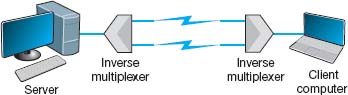
FIGURE 3.8 Inverse multiplexer
3.2 GET MORE BANDWIDTH FOR LESS
MANAGEMENT FOCUS
Upstart network provider Yipes is among the first to offer network services based on wavelength division multiplexing (WDM). It offers circuits that range from 1 Mbps up to 1 Gbps in 1-Mbps increments and costs anywhere between 10 percent and 80 percent of the cost of traditional services.
___________
SOURCE: Yipes.com.
3.2.4 How DSL Transmits Data
The reason for the limited capacity on voice telephone circuits lies with the telephone and the switching equipment at the telephone company offices. The actual twisted pair wire in the local loop is capable of providing much higher data transmission rates. Digital Subscriber Line (DSL) is one approach to changing the way data are transmitted in the local loop to provide higher-speed data transfer. DSL is a family of techniques that combines analog transmission and FDM to provide a set of voice and data circuits. There are many different types of DSL, so many in fact that DSL is sometimes called xDSL, where the x is intended to represent one of the many possible flavors. Chapter 9 examines the different types of DSL.
With DSL, a DSL modem (called customer premises equipment [CPE]) is installed in the customer's home or office and another DSL modem is installed at the telephone company switch closest to the customer's home or office. The modem is first an FDM device that splits the physical circuit into three logical circuits: a standard voice circuit used for telephone calls, an upstream data circuit from the customer to the telephone switch, and a downstream data circuit from the switch to the customer. TDM is then used within the two data channels to provide a set of one or more individual channels that can be used to carry different data. A combination of amplitude and phase modulation is used in the data circuits to provide the desired data rate (the exact combination depends on which flavor of DSL is used).2 One version of DSL called G.Lite ASDL provides one voice circuit, a 1.5-Mbps downstream circuit, and a 384-Kbps upstream channel.
3.3 COMMUNICATION MEDIA
The medium (or media, if there is more than one) is the physical matter or substance that carries the voice or data transmission. Many different types of transmission media are currently in use, such as copper (wire), glass or plastic (fiber-optic cable), or air (radio, microwave, or satellite). There are two basic types of media. Guided media are those in which the message flows through a physical media such as a twisted pair wire, coaxial cable, or fiber-optic cable; the media “guides” the signal. Wireless media are those in which the message is broadcast through the air, such as microwave or satellite.
In many cases, the circuits used in WANs are provided by the various common carriers who sell usage of them to the public. We call the circuits sold by the common carriers communication services. Chapter 8 describes specific services available in North America. The following sections describe the medium and the basic characteristics of each circuit type, in the event you were establishing your own physical network, whereas Chapter 8 describes how the circuits are packaged and marketed for purchase or lease from a common carrier. If your organization has leased a circuit from a common carrier, you are probably less interested in the media used and more interested in whether the speed, cost, and reliability of the circuit meets your needs.
3.3.1 Twisted Pair Cable
One of the most commonly used types of guided media is twisted pair cable, insulated pairs of wires that can be packed quite close together (Figure 3.9). The wires usually are twisted to minimize the electromagnetic interference between one pair and any other pair in the bundle. Your house or apartment probably has a set of two twisted pair wires (i.e., four wires) from it to the telephone company network. One pair is used to connect your telephone; the other pair is a spare that can be used for a second telephone line. The twisted pair cable used in LANs are usually packaged as four sets of pairs as shown in Figure 3.9, whereas bundles of several thousand wire pairs are placed under city streets and in large buildings. The specific types of twisted pair cable used in LANs, such as Cat 5e and Cat 6, are discussed in Chapter 6.

FIGURE 3.9 Category 5e twisted pair wire
Source:© Jason/Alamy

FIGURE 3.10 Coaxial cables. Thinnet and Thicknet Ethernet cables (right) and cross-sectional view (left)
Source:© Tony Freeman/PhotoEdit
3.3.2 Coaxial Cable
Coaxial cable is a type of guided media that is quickly disappearing (Figure 3.10). Coaxial cable has a copper core (the inner conductor) with an outer cylindrical shell for insulation. The outer shield, just under the shell, is the second conductor. Because they have additional shielding provided by their multiple layers of material, coaxial cables are less prone to interference and errors than basic low-cost twisted pair wires. Coaxial cables cost about three times as much as twisted pair wires but offer few additional benefits other than better shielding. One can also buy specially shielded twisted pair wire that provides the same level of quality as coaxial cable but at half its cost. For this reason, few companies are installing coaxial cable today, although some still continue to use existing coaxial cable that was installed years ago.
3.3.3 Fiber-Optic Cable
Although twisted pair is the most common type of guided media, fiber-optic cable also is becoming widely used. Instead of carrying telecommunication signals in the traditional electrical form, this technology uses high-speed streams of light pulses from lasers or LEDs (light-emitting diodes) that carry information inside hair-thin strands of glass called optical fibers. Figure 3.11 shows a fiber-optic cable and depicts the optical core, the cladding (metal coating), and how light rays travel in optical fibers.
The earliest fiber-optic systems were multimode, meaning that the light could reflect inside the cable at many different angles. Multimode cables are plagued by excessive signal weakening (attenuation) and dispersion (spreading of the signal so that different parts of the signal arrive at different times at the destination). For these reasons, early multimode fiber was usually limited to about 500 meters. Graded-index multimode fiber attempts to reduce this problem by changing the refractive properties of the glass fiber so that as the light approaches the outer edge of the fiber, it speeds up, which compensates for the slightly longer distance it must travel compared with light in the center of the fiber. Therefore, the light in the center is more likely to arrive at the same time as the light that has traveled at the edges of the fiber. This increases the effective distance to just under 1,000 meters.

FIGURE 3.11 Fiber-optic cable
Source:© Hugh Threlfall/Alamy
Single-mode fiber-optic cables transmit a single direct beam of light through a cable that ensures the light reflects in only one pattern, in part because the core diameter has been reduced from 50 microns to about 5 to 10 microns. This smaller-diameter core allows the fiber to send a more concentrated light beam, resulting in faster data transmission speeds and longer distances, often up to 100 kilometers. However, because the light source must be perfectly aligned with the cable, single-mode products usually use lasers (rather than the LEDs used in multimode systems) and therefore are more expensive.
Fiber-optic technology is a revolutionary departure from the traditional copper wires of twisted pair cable or coaxial cable. One of the main advantages of fiber optics is that it can carry huge amounts of information at extremely fast data rates. This capacity makes it ideal for the simultaneous transmission of voice, data, and image signals. In most cases, fiber-optic cable works better under harsh environmental conditions than do its metallic counterparts. It is not as fragile or brittle, it is not as heavy or bulky, and it is more resistant to corrosion. Also, in case of fire, an optical fiber can withstand higher temperatures than can copper wire. Even when the outside jacket surrounding the optical fiber has melted, a fiber-optic system still can be used.
3.3.4 Radio
One of the most commonly used forms of wireless media is radio; when people used the term wireless, they usually mean radio transmission. When you connect your laptop into the network wirelessly, you are using radio transmission. Radio data transmission uses the same basic principles as standard radio transmission. Each device or computer on the network has a radio receiver/transmitter that uses a specific frequency range that does not interfere with commercial radio stations. The transmitters are very low power, designed to transmit a signal only a short distance, and are often built into portable computers or handheld devices such as phones and personal digital assistants. Wireless technologies for LAN environments, such as IEEE 802.11n, are discussed in more detail in Chapter 7.
3.3 MUNICH AIRPORT PROVIDES WIRELESS HOTSPOTS
MANAGEMENT FOCUS
Munich is Germany's second-largest commercial airport, handling over 23 million passengers per year. It began offering wireless Internet access in its terminal buildings and main concourse in October 2001 and was the first wireless local area network provider to give users a choice of Internet Service Providers (ISP).
Travelers can use their home or work ISP when on the move, greatly simplifying access and billing. ISPs, which will benefit from increased loyalty and revenues, are already planning to use the pioneering multi-service provider concept elsewhere, so ultimately users may be able to travel wherever they want without having to change ISP or pay additional fees.
The hotspots are located throughout the airport. Users simply have to turn on their wireless-equipped computers and they will immediately have access to the network. If they are not existing customers of one of the offered ISPs, they can choose to access the Internet by paying €5.00–€8.00 per hour, depending upon the ISP.
___________
SOURCE: “Munich Airport Uses Cisco Technology to Break New WiFi Ground with the World's First Multiple ISP Hotspot” www.cisco.com, and “Wireless LAN pilot project a success. Up to 3,000 users a month tap in to wireless Internet access,” www.munich-airport.de.
3.3.5 Microwave
Microwave transmission is an extremely high-frequency radio communication beam that is transmitted over a direct line-of-sight path between any two points. As its name implies, a microwave signal is an extremely short wavelength, thus the word micro wave. Microwave radio transmissions perform the same functions as cables. For example, point A communicates with point B via a through-the-air microwave transmission path, instead of a copper wire cable. Because microwave signals approach the frequency of visible light waves, they exhibit many of the same characteristics as light waves, such as reflection, focusing, or refraction. As with visible light waves, microwave signals can be focused into narrow, powerful beams that can be projected over long distances. Just as a parabolic reflector focuses a searchlight into a beam, a parabolic reflector also focuses a high-frequency microwave into a narrow beam. Towers are used to elevate the radio antennas to account for the earth's curvature and maintain a clear line-of-sight path between the two parabolic reflectors; see Figure 3.12.

FIGURE 3.12 A microwave tower. The round antennas are microwave antennas and the straight antennas are cell phone antennas.
Source: Matej, Pribelsky listock photo
This transmission medium is typically used for long-distance data or voice transmission. It does not require the laying of any cable, because long-distance antennas with microwave repeater stations can be placed approximately 25 to 50 miles apart. A typical long-distance antenna might be 10 feet wide, although over shorter distances in the inner cities, the dish antennas can be less than 2 feet in diameter. The airwaves in larger cities are becoming congested because so many microwave dish antennas have been installed that they interfere with one another.
3.3.6 Satellite
Satellite transmission is similar to microwave transmission except instead of transmission involving another nearby microwave dish antenna, it involves a satellite many miles up in space. Figure 3.13 depicts a geosynchronous satellite. Geosynchronous means that the satellite remains stationary over one point on the earth. One disadvantage of satellite transmission is the propagation delay that occurs because the signal has to travel out into space and back to earth, a distance of many miles that even at the speed of light can be noticeable. Low earth orbit (LEO) satellites are placed in lower orbits to minimize propogation delay. Satellite transmission is sometimes also affected by raindrop attenuation when satellite transmissions are absorbed by heavy rain. It is not a major problem, but engineers need to work around it.
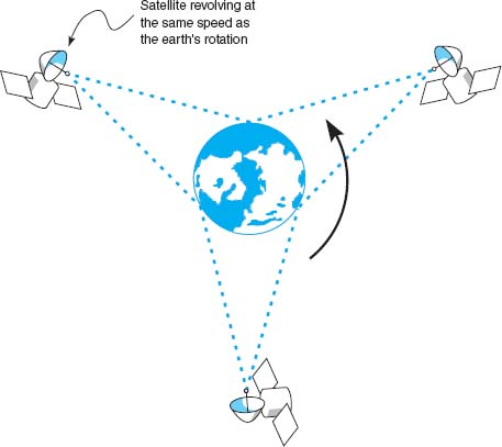
FIGURE 3.13 Satellites in operation
3.4 SATELLITE COMMUNICATIONS IMPROVE PERFORMANCE
MANAGEMENT FOCUS
Boyle Transportation hauls hazardous materials nationwide for both commercial customers and the government, particularly the U.S. Department of Defense. The Department of Defense recently mandated that hazardous materials contractors use mobile communications systems with up-to-the-minute monitoring when hauling the department's hazardous cargoes.
After looking at the alternatives, Boyle realized that it would have to build its own system. Boyle needed a relational database at its operations center that contained information about customers, pickups, deliveries, truck location, and truck operating status. Data are distributed from this database via satellite to an antenna on each truck. Now, at any time, Boyle can notify the designated truck to make a new pickup via the bidirectional satellite link and record the truck's acknowledgment.
Each truck contains a mobile data terminal connected to the satellite network. Each driver uses a keyboard to enter information, which transmits the location of the truck. These satellite data are received by the main offices via a leased line from the satellite earth station.
This system increased productivity by an astounding 80% over two years; administration costs increased by only 20%.
3.3.7 Media Selection
Which media are best? It is hard to say, particularly when manufacturers continue to improve various media products. Several factors are important in selecting media (Figure 3.14).
- The type of network is one major consideration. Some media are used only for WANs (microwaves and satellite), whereas others typically are not (twisted pair, coaxial cable, and radio), although we should note that some old WAN networks still use twisted pair cable. Fiber-optic cable is unique in that it can be used for virtually any type of network.
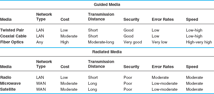
FIGURE 3.14 Media summary. BN = backbone network; LAN = local area network; WAN = wide area network
- Cost is always a factor in any business decision. Costs are always changing as new technologies are developed and as competition among vendors drives prices down. Among the guided media, twisted pair wire is generally the cheapest, coaxial cable is somewhat more expensive, and fiber-optic cable is the most expensive. The cost of the wireless media is generally driven more by distance than any other factor. For very short distances (several hundred meters), radio is the cheapest; for moderate distances (several hundred miles), microwave is cheapest; and for long distances, satellite is cheapest.
- Transmission distance is a related factor. Twisted-pair wire coaxial cable and radio can transmit data only a short distance before the signal must be regenerated. Twisted-pair wire and radio typically can transmit up to 100 to 300 meters, and coaxial cable typically between 200 and 500 meters. Fiber optics can transmit up to 75 miles, and new types of fiber-optic cable can reach more than 600 miles.
- Security is primarily determined by whether the media are guided or wireless. Wireless media (radio, microwave, and satellite) are the least secure because their signals are easily intercepted. Guided media (twisted pair, coaxial, and fiber optics) are more secure, with fiber optics being the most secure.
- Error rates are also important. Wireless media are most susceptible to interference and thus have the highest error rates. Among the guided media, fiber optics provides the lowest error rates, coaxial cable the next best, and twisted pair cable the worst, although twisted pair cable is generally better than the wireless media.
- Transmission speeds vary greatly among the different media. It is difficult to quote specific speeds for different media because transmission speeds are constantly improving and because they vary within the same type of media, depending on the specific type of cable and the vendor. In general, twisted pair cable and coaxial cable can provide data rates of between 1 Mbps (1 million bits per second) and 1 Gbps (1 billion bits per second), whereas fiber-optic cable ranges between 1 Gbps and 40 Gbps. Radio, microwave, and satellite generally provide 10 to 100 Mbps.
3.4 DIGITAL TRANSMISSION OF DIGITAL DATA
All computer systems produce binary data. For these data to be understood by both the sender and receiver, both must agree on a standard system for representing the letters, numbers, and symbols that compose messages. The coding scheme is the language that computers use to represent data.
3.4.1 Coding
A character is a symbol that has a common, constant meaning. A character might be the letter A or B, or it might be a number such as 1 or 2. Characters also may be special symbols such as ? or &. Characters in data communications, as in computer systems, are represented by groups of bits that are binary zeros (0) and ones (1). The groups of bits representing the set of characters that are the “alphabet” of any given system are called a coding scheme, or simply a code.
A byte is a group of consecutive bits that is treated as a unit or character. One byte normally is composed of 8 bits and usually represents one character; however, in data communications, some codes use 5, 6, 7, 8, or 9 bits to represent a character. For example, representation of the character A by a group of 8 bits (say, 01 000 001) is an example of coding.
There are three predominant coding schemes in use today. United States of America Standard Code for Information Interchange (USASCII, or, more commonly, ASCII) is the most popular code for data communications and is the standard code on most microcomputers. There are two types of ASCII; one is a 7-bit code that has 128 valid character combinations, and the other is an 8-bit code that has 256 combinations. The number of combinations can be determined by taking the number 2 and raising it to the power equal to the number of bits in the code because each bit has two possible values, a 0 or a 1. In this case 27 = 128 characters or 28 = 256 characters.
A second commonly used coding scheme is ISO 8859, which is standardized by the International Standards Organization. ISO 8859 is an 8-bit code that includes the ASCII codes plus non-English letters used by many European languages (e.g., letters with accents). If you look closely at Figure 2.19, you will see that HTML often uses ISO 8859.
Unicode is the other commonly used coding scheme. There are many different versions of Unicode. UTF-8 is an 8-bit version which is very similar to ASCII. UTF-16, which uses 16 bits per character (i.e., two bytes, called a “word”), is used by Windows. By using more bits, UTF-16 can represent many more characters beyond the usual English or Latin characters, such as Cyrillic or Chinese.
We can choose any pattern of bits we like to represent any character we like, as long as all computers understand what each bit pattern represents. Figure 3.15 shows the eight-bit binary bit patterns used to represent a few of the characters we use in ASCII.
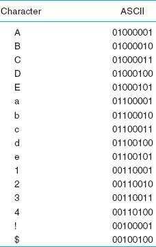
FIGURE 3.15 Binary numbers used to represent different characters using ASCII
TECHNICAL FOCUS
There are two general categories of electrical current: direct current and alternating current. Current is the movement or flow of electrons, normally from positive (+) to negative (−). The plus (+) or minus (−) measurements are known as polarity. Direct current (DC) travels in only one direction, whereas alternating current (AC) travels first in one direction and then in the other direction.
A copper wire transmitting electricity acts like a hose transferring water. We use three common terms when discussing electricity. Voltage is defined as electrical pressure—the amount of electrical force pushing electrons through a circuit. In principle, it is the same as pounds per square inch in a water pipe. Amperes (amps) are units of electrical flow, or volume. This measure is analogous to gallons per minute for water. The watt is the fundamental unit of electrical power. It is a rate unit, not a quantity. You obtain the wattage by multiplying the volts by the amperes.
3.4.2 Transmission Modes
Parallel Parallel transmission is the way the internal transfer of binary data takes place inside a computer. If the internal structure of the computer is 8 bit, then all 8 bits of the data element are transferred between main memory and the central processing unit simultaneously on 8 separate connections. The same is true of computers that use a 32-bit structure; all 32 bits are transferred simultaneously on 32 connections.
Figure 3.16 shows how all 8 bits of one character could travel down a parallel communication circuit. The circuit is physically made up of 8 separate wires, wrapped in one outer coating. Each physical wire is used to send 1 bit of the 8-bit character. However, as far as the user is concerned (and the network for that matter), there is only one circuit; each of the wires inside the cable bundle simply connects to a different part of the plug that connects the computer to the bundle of wire.
Serial Serial transmission means that a stream of data is sent over a communication circuit sequentially in a bit-by-bit fashion as shown in Figure 3.17. In this case, there is only one physical wire inside the bundle and all data must be transmitted over that one physical wire. The transmitting device sends one bit, then a second bit, and so on, until all the bits are transmitted. It takes n iterations or cycles to transmit n bits. Thus, serial transmission is considerably slower than parallel transmission—eight times slower in the case of 8-bit ASCII (because there are 8 bits). Compare Figure 3.17 with Figure 3.16.
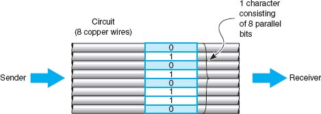
FIGURE 3.16 Parallel transmission of an 8-bit code

FIGURE 3.17 Serial transmission of an 8-bit code
3.4.3 Digital Transmission
Digital transmission is the transmission of binary electrical or light pulses in that it only has two possible states, a 1 or a 0. The most commonly encountered voltage levels range from a low of +3/−3 to a high of +24/−24 volts. Digital signals are usually sent over wire of no more than a few thousand feet in length.
All digital transmission techniques require a set of symbols (to define how to send a 1 and a 0), and the symbol rate (how many symbols will be sent per second).
Figure 3.18 shows five types of digital transmission techniques. With unipolar signaling, the voltage is always positive or negative (like a DC current). Figure 3.18 illustrates a unipolar technique in which a signal of 0 volts (no current) is used to transmit a zero, and a signal of +5 volts is used to transmit a 1.
An obvious question at this point is this: If 0 volts means a zero, how do you send no data? This is discussed in detail in Chapter 4. For the moment, we will just say that there are ways to indicate when a message starts and stops, and when there are no messages to send, the sender and receiver agree to ignore any electrical signal on the line.
To successfully send and receive a message, both the sender and receiver have to agree on how often the sender can transmit data—that is, on the symbol rate. For example, if the symbol rate on a circuit is 64 Hertz (Hz) (64,000 symbols per second), then the sender changes the voltage on the circuit once every 1/64,000 of a second and the receiver must examine the circuit every 1/64,000 of a second to read the incoming data.
In bipolar signaling, the ones and zeros vary from a plus voltage to a minus voltage (like an AC current). The first bipolar technique illustrated in Figure 3.18 is called nonreturn to zero (NRZ) because the voltage alternates from +5 volts (a symbol indicating a 1) and −5 volts (a symbol indicating a 0) without ever returning to 0 volts. The second bipolar technique in this figure is called return to zero (RZ) because it always returns to 0 volts after each bit before going to +5 volts (the symbol for a 1) or −5 volts (the symbol for a 0). The third bipolar technique, is called alternate mark inversion (AMI) because a 0 is always sent using 0 volts, but 1’s alternate between +5 volts and − 5 volts. AMI is used on T1 and T3 circuits. In Europe, bipolar signaling sometimes is called double current signaling because you are moving between a positive and negative voltage potential.
In general, bipolar signaling experiences fewer errors than unipolar signaling because the symbols are more distinct. Noise or interference on the transmission circuit is less likely to cause the bipolar's +5 volts to be misread as a −5 volts than it is to cause the unipolar's 0 volts as a +5 volts. This is because changing the polarity of a current (from positive to negative, or vice versa) is more difficult than changing its magnitude.

FIGURE 3.18 Unipolar, bipolar, and Manchester signals (digital)
3.4.4 How Ethernet Transmits Data
The most common technology used in LANs is Ethernet3; if you are working in a computer lab on campus, you are most likely using Ethernet. Ethernet uses digital transmission over either serial or parallel circuits, depending on which version of Ethernet you use. One version of Ethernet that uses serial transmission requires 1/10,000,000 of a second to send one symbol; that is, it transmits 10 million symbols (each of 1 bit) per second. This gives a data rate of 10 Mbps, and if we assume that there are 8 bits in each character, this means that about 1.25 million characters can be transmitted per second in the circuit.
Ethernet uses Manchester encoding, which is a special type of bipolar signaling in which the signal is changed from high to low or from low to high in the middle of the signal. A change from high to low is used to represent a 0, whereas the opposite (a change from low to high) is used to represent a 1. See Figure 3.18. Manchester encoding is less susceptible to having errors go undetected, because if there is no transition in midsignal the receiver knows that an error must have occurred.
3.5 ANALOG TRANSMISSION OF DIGITAL DATA
Telephone networks were originally built for human speech rather than for data. They were designed to transmit the electrical representation of sound waves, rather than the binary data used by computers. There are many occasions when data need to be transmitted over a voice communications network. Many people working at home still use a modem over their telephone line to connect to the Internet.
The telephone system (commonly called POTS for plain old telephone service) enables voice communication between any two telephones within its network. The telephone converts the sound waves produced by the human voice at the sending end into electrical signals for the telephone network. These electrical signals travel through the network until they reach the other telephone and are converted back into sound waves.
Analog transmission occurs when the signal sent over the transmission media continuously varies from one state to another in a wave-like pattern much like the human voice. Modems translate the digital binary data produced by computers into the analog signals required by voice transmission circuits. One modem is used by the transmitter to produce the analog signals and a second by the receiver to translate the analog signals back into digital signals.
The sound waves transmitted through the voice circuit have three important characteristics (see Figure 3.19). The first is the height of the wave, called amplitude. Amplitude is measured in decibels (dB). Our ears detect amplitude as the loudness or volume of sound. Every sound wave has two parts, half above the zero amplitude point (i.e., positive) and half below (i.e., negative), and both halves are always the same height.
The second characteristic is the length of the wave, usually expressed as the number of waves per second, or frequency. Frequency is expressed in hertz (Hz).4 Our ears detect frequency as the pitch of the sound. Frequency is the inverse of the length of the sound wave, so that a high frequency means that there are many short waves in a 1-second interval, whereas a low frequency means that there are fewer (but longer) waves in 1 second.
The third characteristic is the phase, which refers to the direction in which the wave begins. Phase is measured in the number of degrees (°). The wave in Figure 3.19 starts up and to the right, which is defined as 0° phase wave. Waves can also start down and to the right (a 180° phase wave), and in virtually any other part of the sound wave.

3.5.1 Modulation
When we transmit data through the telephone lines, we use the shape of the sound waves we transmit (in terms of amplitude, frequency, and phase) to represent different data values. We do this by transmitting a simple sound wave through the circuit (called the carrier wave) and then changing its shape in different ways to represent a 1 or a 0. Modulation is the technical term used to refer to these “shape changes.” There are three fundamental modulation techniques: amplitude modulation, frequency modulation, and phase modulation. Once again, the sender and receiver have to agree on what symbols will be used (what amplitude, frequency, and phase will represent a 1 and a 0) and on the symbol rate (how many symbols will be sent per second).
Basic Modulation With amplitude modulation (AM) (also called amplitude shift keying [ASK]), the amplitude or height of the wave is changed. One amplitude is the symbol defined to be 0, and another amplitude is the symbol defined to be a 1. In the AM shown in Figure 3.20, the highest amplitude symbol (tallest wave) represents a binary 1 and the lowest amplitude symbol represents a binary 0. In this case, when the sending device wants to transmit a 1, it would send a high-amplitude wave (i.e., a loud signal). AM is more susceptible to noise (more errors) during transmission than is frequency modulation or phase modulation.
Frequency modulation (FM) (also called frequency shift keying [FSK]) is a modulation technique whereby each 0 or 1 is represented by a number of waves per second (i.e., a different frequency). In this case, the amplitude does not vary. One frequency (i.e., a certain number of waves per second) is the symbol defined to be a 1, and a different frequency (a different number of waves per second) is the symbol defined to be a 0. In Figure 3.21, the higher frequency wave symbol (more waves per time period) equals a binary 1, and the lower frequency wave symbol equals a binary 0.

FIGURE 3.20 Amplitude modulation
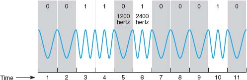
FIGURE 3.21 Frequency modulation
Phase modulation (PM) (also called phase shift keying [PSK]) is the most difficult to understand. Phase refers to the direction in which the wave begins. Until now, the waves we have shown start by moving up and to the right (this is called a 0° phase wave). Waves can also start down and to the right. This is called a phase of 180°. With phase modulation, one phase symbol is defined to be a 0 and the other phase symbol is defined to be a 1. Figure 3.22 shows the case where a phase of 0° symbol is defined to be a binary 0 and a phase of 180° symbol is defined to be a binary 1.
Sending Multiple Bits Simultaneously Each of the three basic modulation techniques (AM, FM, and PM) can be refined to send more than 1 bit at one time. For example, basic AM sends 1 bit per wave (or symbol) by defining two different amplitudes, one for a 1 and one for a 0. It is possible to send 2 bits on one wave or symbol by defining four different amplitudes. Figure 3.23 shows the case where the highest-amplitude wave is defined to be a symbol representing two bits, both 1’s. The next highest amplitude is the symbol defined to mean first a 1 and then a 0, and so on.
This technique could be further refined to send 3 bits at the same time by defining 8 different symbols, each with different amplitude levels or 4 bits by defining 16 symbols, each with different amplitude levels, and so on. At some point, however, it becomes very difficult to differentiate between the different amplitudes. The differences are so small that even a small amount of noise could destroy the signal.
This same approach can be used for FM and PM. Two bits could be sent on the same symbol by defining four different frequencies, one for 11, one for 10, and so on, or by defining four phases (0°, 90°, 180°, and 270°). Three bits could be sent by defining symbols with eight frequencies or eight phases (0°, 45°, 90°, 135°, 180°, 225°, 270°, and 315°). These techniques are also subject to the same limitations as AM; as the number of different frequencies or phases becomes larger, it becomes difficult to differentiate among them.


FIGURE 3.23 Two-bit amplitude modulation
It is also possible to combine modulation techniques—that is, to use AM, FM, and PM techniques on the same circuit. For example, we could combine AM with four defined amplitudes (capable of sending 2 bits) with FM with four defined frequencies (capable of sending 2 bits) to enable us to send 4 bits on the same symbol.
One popular technique is quadrature amplitude modulation (QAM). QAM involves splitting the symbol into eight different phases (3 bits) and two different amplitudes (1 bit), for a total of 16 different possible values. Thus, one symbol in QAM can represent 4 bits, while 256-QAM sends 8 bits per symbol. 64-QAM and 256-QAM are commonly used in digital TV services and cable modem Internet services.
Bit Rate versus Baud Rate versus Symbol Rate The terms bit rate (i.e., the number bits per second transmitted) and baud rate are used incorrectly much of the time. They often are used interchangeably, but they are not the same. In reality, the network designer or network user is interested in bits per second because it is the bits that are assembled into characters, characters into words and, thus, business information.
A bit is a unit of information. A baud is a unit of signaling speed used to indicate the number of times per second the signal on the communication circuit changes. Because of the confusion over the term baud rate among the general public, ITU-T now recommends the term baud rate be replaced by the term symbol rate. The bit rate and the symbol rate (or baud rate) are the same only when 1 bit is sent on each symbol. For example, if we use AM with two amplitudes, we send 1 bit on one symbol. Here, the bit rate equals the symbol rate. However, if we use QAM, we can send 4 bits on every symbol; the bit rate would be four times the symbol rate. If we used 64-QAM, the bit rate would be six times the symbol rate. Virtually all of today's modems send multiple bits per symbol.
3.5.2 Capacity of a Circuit
The data capacity of a circuit is the fastest rate at which you can send your data over the circuit in terms of the number of bits per second. The data rate (or bit rate) is calculated by multiplying the number of bits sent on each symbol by the maximum symbol rate. As we discussed in the previous section, the number of bits per symbol depends on the modulation technique (e.g., QAM sends 4 bits per symbol).
The maximum symbol rate in any circuit depends on the bandwidth available and the signal-to-noise ratio (the strength of the signal compared with the amount of noise in the circuit). The bandwidth is the difference between the highest and the lowest frequencies in a band or set of frequencies. The range of human hearing is between 20 Hz and 14,000 Hz, so its bandwidth is 13,880 Hz. The maximum symbol rate for analog transmission is usually the same as the bandwidth as measured in Hertz. If the circuit is very noisy, the maximum symbol rate may fall as low as 50% of the bandwidth. If the circuit has very little noise, it is possible to transmit at rates up to the bandwidth.
Digital transmission symbol rates can reach as high as two times the bandwidth for techniques that have only one voltage change per symbol (e.g., NRZ). For digital techniques that have two voltage changes per symbol (e.g., RZ, Manchester), the maximum symbol rate is the same as the bandwidth.
Standard telephone lines provide a bandwidth of 4,000 Hz. Under perfect circumstances, the maximum symbol rate is therefore about 4,000 symbols per second. If we were to use basic AM (1 bit per symbol), the maximum data rate would be 4,000 bits per second (bps). If we were to use QAM (4 bits per symbol), the maximum data rate would be 4 bits per symbol × 4,000 symbols per second = 16,000 bps. A circuit with a 10 MHz bandwidth using 64-QAM could provide up to 60 Mbps.
3.5.3 How Modems Transmit Data
The modem (an acronym for modulator/demodulator) takes the digital data from a computer in the form of electrical pulses and converts them into the analog signal that is needed for transmission over an analog voice-grade circuit. There are many different types of modems available today from dial-up modems to cable modems. For data to be transmitted between two computers using modems, both need to use the same type of modem. Fortunately, several standards exist for modems, and any modem that conforms to a standard can communicate with any other modem that conforms to the same standard.
A modem's data transmission rate is the primary factor that determines the throughput rate of data, but it is not the only factor. Data compression can increase throughput of data over a communication link by literally compressing the data. V.44, the ISO standard for data compression, uses Lempel-Ziv encoding. As a message is being transmitted, Lempel-Ziv encoding builds a dictionary of two-, three-, and four-character combinations that occur in the message. Anytime the same character pattern reoccurs in the message, the index to the dictionary entry is transmitted rather than sending the actual data. The reduction provided by V.44 compression depends on the actual data sent but usually averages about 6:1 (i.e., almost six times as much data can be sent per second using V.44 as without it).
3.6 DIGITAL TRANSMISSION OF ANALOG DATA
In the same way that digital computer data can be sent over analog telephone networks using analog transmission, analog voice data can be sent over digital networks using digital transmission. This process is somewhat similar to the analog transmission of digital data. A pair of special devices called codecs (code/decode) is used in the same way that a pair of modems is used to translate the data to send across the circuit. One codec is attached to the source of the signal (e.g., a telephone or the local loop at the end office) and translates the incoming analog voice signal into a digital signal for transmission across the digital circuit. A second codec at the receiver's end translates the digital data back into analog data.
3.6.1 Translating from Analog to Digital
Analog voice data must first be translated into a series of binary digits before they can be transmitted over a digital circuit. This is done by sampling the amplitude of the sound wave at regular intervals and translating it into a binary number. Figure 3.24 shows an example where eight different amplitude levels are used (i.e., each amplitude level is represented by three bits). The top diagram shows the original signal, and the bottom diagram, the digitized signal.
A quick glance will show that the digitized signal is only a rough approximation of the original signal. The original signal had a smooth flow, but the digitized signal has jagged “steps.” The difference between the two signals is called quantizing error. Voice transmissions using digitized signals that have a great deal of quantizing error sound metallic or machinelike to the ear.
There are two ways to reduce quantizing error and improve the quality of the digitized signal, but neither is without cost. The first method is to increase the number of amplitude levels. This minimizes the difference between the levels (the “height” of the “steps”) and results in a smoother signal. In Figure 3.24, we could define 16 amplitude levels instead of eight levels. This would require 4 bits (rather than the current 3 bits) to represent the amplitude, thus increasing the amount of data needed to transmit the digitized signal.
No amount of levels or bits will ever result in perfect-quality sound reproduction, but in general, 7 bits (27 = 128 levels) reproduces human speech adequately. Music, on the other hand, typically uses 16 bits (216 = 65,536 levels).
The second method is to sample more frequently. This will reduce the “length” of each “step,” also resulting in a smoother signal. To obtain a reasonable-quality voice signal, one must sample at least twice the highest possible frequency in the analog signal. You will recall that the highest frequency transmitted in telephone circuits is 4,000 Hz. Thus, the methods used to digitize telephone voice transmissions must sample the input voice signal at a minimum of 8,000 times per second. Sampling more frequently than this (called oversampling) will improve signal quality. RealNetworks.com, which produces Real Audio and other Web-based tools, sets its products to sample at 48,000 times per second to provide higher quality. The iPod and most CDs sample at 44,100 times per second and use 16 bits per sample to produce almost error-free music. Some other MP3 players sample less frequently and use fewer bits per sample to produce smaller transmissions, but the sound quality may suffer.
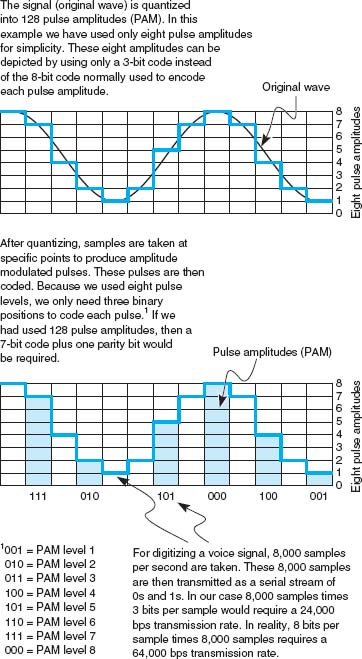
FIGURE 3.24 Pulse amplitude modulation (PAM)
3.6.2 How Telephones Transmit Voice Data
When you make a telephone call, the telephone converts your analog voice data into a simple analog signal and sends it down the circuit from your home to the telephone company's network. This process is almost unchanged from the one used by Bell when he invented the telephone in 1876. With the invention of digital transmission, the common carriers (i.e., the telephone companies) began converting their voice networks to use digital transmission. Today, all of the common carrier networks use digital transmission, except in the local loop (sometimes called the last mile), the wires that run from your home or business to the telephone switch that connects your local loop into the telephone network. This switch contains a codec that converts the analog signal from your phone into a digital signal. This digital signal is then sent through the telephone network until it hits the switch for local loop for the person you are calling. This switch uses its codec to convert the digital signal used inside the phone network back into the analog signal needed by that person's local loop and telephone. See Figure 3.25.

FIGURE 3.25 Pulse amplitude modulation (PAM)
There are many different combinations of sampling frequencies and numbers of bits per sample that could be used. For example, one could sample 4,000 times per second using 128 amplitude levels (i.e., 7 bits) or sample at 16,000 times per second using 256 levels (i.e., 8 bits).
The North American telephone network uses pulse code modulation (PCM). With PCM, the input voice signal is sampled 8,000 times per second. Each time the input voice signal is sampled, 8 bits are generated.5 Therefore, the transmission speed on the digital circuit must be 64,000 bps (8 bits per sample × 8,000 samples per second) to transmit a voice signal when it is in digital form. Thus, the North American telephone network is built using millions of 64 Kbps digital circuits that connect via codecs to the millions of miles of analog local loop circuits into the users’ residences and businesses.
3.6.3 How Instant Messenger Transmits Voice Data
A 64 Kbps digital circuit works very well for transmitting voice data because it provides very good quality. The problem is that it requires a lot of capacity.
Adaptive differential pulse code modulation (ADPCM) is the alternative used by IM and many other applications that provide voice services over lower-speed digital circuits. ADPCM works in much the same way as PCM. It samples incoming voice signal 8,000 times per second and calculates the same 8-bit amplitude value as PCM. However, instead of transmitting the 8-bit value, it transmits the difference between the 8-bit value in the last time interval and the current 8-bit value (i.e., how the amplitude has changed from one time period to another). Because analog voice signals change slowly, these changes can be adequately represented by using only 4 bits. This means that ADPCM can be used on digital circuits that provide only 32 Kbps (4 bits per sample × 8,000 samples per second = 32,000 bps).
Several versions of ADPCM have been developed and standardized by the ITU-T. There are versions designed for 8 Kbps circuits (which send 1 bit 8,000 times per second) and 16 Kbps circuits (which send 2 bits 8,000 times per second), as well as the original 32 Kbps version. However, there is a trade-off here. Although the 32 Kbps version usually provides as good a sound quality as that of a traditional voice telephone circuit, the 8 Kbps and 16 Kbps versions provide poorer sound quality.
3.6.4 Voice over Internet Protocol (VoIP)
Voice over Internet Protocol (VoIP, pronounced voyp) is commonly used to transmit phone conversations over digital networks. VoIP is a relatively new standard that uses digital telephones with built-in codecs to convert analog voice data into digital data (see Figure 3.26). Because the codec is built into the telephone, the telephone transmits digital data and therefore can be connected directly into a local area network, in much the same manner as a typical computer. Because VoIP phones operate on the same networks as computers, we can reduce the amount of wiring needed; with VoIP, we need to operate and maintain only one network throughout our offices, rather than two separate networks—one for voice and one for data. However, this also means that data networks with VoIP phones must be designed to operate in emergencies (to enable 911 calls) even when the power fails; they must have uninterruptable power supplies (UPS) for all network circuits.
One commonly used VoIP standard is G.722 wideband audio, which is a version of ADPCM that operates at 64 Kbps. It samples 8,000 times per second and produces 8 bits per sample.
Because VoIP phones are digital, they can also contain additional capabilities. For example, high-end VoIP phones often contain computer chips to enable them to download and install small software applications so that they can function in many ways like computers.
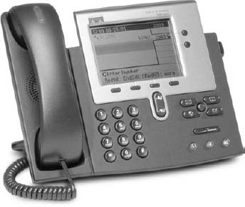
FIGURE 3.26 VoIP phone
Source: Courtesy Cisco Systems, Inc. Unauthorized use not permitted.
3.7 IMPLICATIONS FOR MANAGEMENT
In the past, networks used to be designed so that the physical cables transported data in the same form in which the data was created: Analog voice data generated by telephones used to be carried by analog transmission cables and digital computer data used to be carried by digital transmission cables. Today, it is simple to separate the different types of data (analog voice or digital computer) from the actual physical cables used to carry the data. In most cases, the cheapest and highest-quality media are digital, which means that most data today are transmitted in digital form. Thus, the convergence of voice and video and data at the physical layers is being driven primarily by business reasons: Digital is better.
The change in physical layers also has implications for organizational structure. Voice data used to be managed separately from computer data because they use different types of networks. As the physical networks converge, so too do the organizational units responsible for managing the data. Today, more organizations are placing the management of voice telecommunications into their information systems organizations.
This also has implications for the telecommunications industry. Over the past few years, the historical separation between manufacturers of networking equipment used in organizations and manufacturers of networking equipment used by the telephone companies has crumbled. There have been some big winners and losers in the stock market from the consolidation of these markets.
SUMMARY
Circuits Networks can be configured so that there is a separate circuit from each client to the host (called a point-to-point configuration) or so that several clients share the same circuit (a multipoint configuration). Data can flow through the circuit in one direction only (simplex), in both directions simultaneously (full duplex), or by taking turns so that data sometimes flow in one direction and then in the other (half duplex). A multiplexer is a device that combines several simultaneous low-speed circuits on one higher-speed circuit so that each low-speed circuit believes it has a separate circuit. In general, the transmission capacity of the high-speed circuit must equal or exceed the sum of the low-speed circuits.
Communication Media Media are either guided, in that they travel through a physical cable (e.g., twisted pair wires, coaxial cable, or fiber-optic cable), or wireless, in that they are broadcast through the air (e.g., radio, microwave, or satellite). Among the guided media, fiber-optic cable can transmit data the fastest with the fewest errors and offers greater security but costs the most; twisted pair wire is the cheapest and most commonly used. The choice of wireless media depends more on distance than on any other factor; radio is the cheapest for short distances, microwave is cheapest for moderate distances, and satellite is cheapest for long distances.
Digital Transmission of Digital Data Digital transmission (also called baseband transmission) is done by sending a series of electrical (or light) pulse through the media. Digital transmission is preferred to analog transmission because it produces fewer errors; is more efficient; permits higher maximum transmission rates; is more secure; and simplifies the integration of voice, video, and data on the same circuit. With unipolar digital transmission, the voltage changes between 0 volts to represent a binary 0 and some positive value (e.g., +15 volts) to represent a binary 1. With bipolar digital transmission, the voltage changes polarity (i.e., positive or negative) to represent a 1 or a 0. Bipolar is less susceptible to errors. Ethernet uses Manchester encoding, which is a version of unipolar transmission.
Analog Transmission of Digital Data Modems are used to translate the digital data produced by computers into the analog signals for transmission in today's voice communication circuits. Both the sender and receiver need to have a modem. Data is transmitted by changing (or modulating) a carrier sound wave's amplitude (height), frequency (length), or phase (shape) to indicate a binary 1 or 0. For example, in amplitude modulation, one amplitude is defined to be a 1 and another amplitude is defined to be a 0. It is possible to send more than 1 bit on every symbol (or wave). For example, with amplitude modulation, you could send 2 bits on each wave by defining four amplitude levels. The capacity or maximum data rate that a circuit can transmit is determined by multiplying the symbol rate (symbols per second) by the number of bits per symbol. Generally (but not always), the symbol rate is the same as the bandwidth, so bandwidth is often used as a measure of capacity. V.44 is a data compression standard that can be combined with any of the foregoing types of modems to reduce the amount of data in the transmitted signal by a factor of up to six. Thus, a V.92 modem using V.44 could provide an effective data rate of 56,000 × 6 = 336, 000 bps.
Digital Transmission of Analog Data Because digital transmission is better, analog voice data is sometimes converted to digital transmission. Pulse code modulation (PCM) is the most commonly used technique. PCM samples the amplitude of the incoming voice signal 8,000 times per second and uses 8 bits to represent the signal. PCM produces a reasonable approximation of the human voice, but more sophisticated techniques are needed to adequately reproduce more complex sounds such as music.
KEY TERMS
adaptive differential pulse code modulation (ADPCM)
American Standard Code for Information Interchange (ASCII)
amplitude
amplitude modulation (AM)
amplitude shift keying (ASK)
analog transmission
bandwidth
Bandwidth on Demand
Interoperability
Networking Group (BONDING)
baud rate
bipolar
bit rate
bits per second (bps)
carrier wave
channel
circuit
coaxial cable
codec
coding scheme
customer premises equipment (CPE)
cycles per second
data compression
data rate
digital subscriber line (DSL)
digital transmission
fiber-optic cable
frequency
frequency division multiplexing (FDM)
frequency modulation (FM)
frequency shift keying (FSK)
full-duplex transmission
guardband
guided media
half-duplex transmission
Hertz (Hz)
inverse multiplexing (IMUX)
ISO 8859
Lempel-Ziv encoding
local loop
logical circuit
Manchester encoding
microwave transmission
modem
multipoint circuit
multiplexing
parallel transmission
phase
phase modulation (PM)
phase shift keying (PSK)
physical circuit
plain old telephone service (POTS)
point-to-point circuit
polarity
pulse code modulation (PCM)
quadrature amplitude modulation (QAM)
quantizing error
radio transmission
retrain time
satellite transmission
serial transmission
simplex transmission
statistical time division multiplexing (STDM)
switch
symbol rate
time division multiplexing (TDM)
turnaround time
twisted pair cable
unicode
unipolar
V.44
Voice over Internet Protocol (VoIP)
wavelength division multiplexing (WDM)
wireless media
QUESTIONS
- How does a multipoint circuit differ from a point-to-point circuit?
- Describe the three types of data flows.
- Describe three types of guided media.
- Describe four types of wireless media.
- How does analog data differ from digital data?
- Clearly explain the differences among analog data, analog transmission, digital data, and digital transmission.
- Explain why most telephone company circuits are now digital.
- What is coding?
- Briefly describe three important coding schemes.
- How are data transmitted in parallel?
- What feature distinguishes serial mode from parallel mode?
- How does bipolar signaling differ from unipolar signaling? Why is Manchester encoding more popular than either?
- What are three important characteristics of a sound wave?
- What is bandwidth? What is the bandwidth in a traditional North American telephone circuit?
- Describe how data could be transmitted using amplitude modulation.
- Describe how data could be transmitted using frequency modulation.
- Describe how data could be transmitted using phase modulation.
- Describe how data could be transmitted using a combination of modulation techniques.
- Is the bit rate the same as the symbol rate? Explain.
- What is a modem?
- What is quadrature amplitude modulation (QAM).
- What is 64-QAM?
- What factors affect transmission speed?
- What is oversampling?
- Why are data compression so useful?
- What data compression standard uses Lempel-Ziv encoding? Describe how it works.
- Explain how pulse code modulation (PCM) works.
- What is quantizing error?
- What is the term used to describe the placing of two or more signals on a single circuit?
- What is the purpose of multiplexing?
- How does DSL (digital subscriber line) work?
- Of the different types of multiplexing, what distinguishes
- frequency division multiplexing (FDM)?
- time division multiplexing (TDM)?
- statistical time division multiplexing (STDM)?
- wavelength division multiplexing (WDM)?
- What is the function of inverse multiplexing (IMUX)?
- If you were buying a multiplexer, why would you choose either TDM or FDM? Why?
- Some experts argue that modems may soon become obsolete. Do you agree? Why or why not?
- What is the maximum capacity of an analog circuit with a bandwidth of 4,000 Hz using QAM?
- What is the maximum data rate of an analog circuit with a 10 MHz bandwidth using 64-QAM and V.44?
- What is the capacity of a digital circuit with a symbol rate of 10 MHz using Manchester encoding?
- What is the symbol rate of a digital circuit providing 100 Mbps if it uses bipolar NRz signaling?
- What is VoIP?
EXERCISES
3-1. Investigate the costs of dumb terminals, network computers, minimally equipped personal computers, and top-of-the-line personal computers. Many equipment manufacturers and resellers are on the Web, so it's a good place to start looking.
3-2. Investigate the different types of cabling used in your organization and where they are used (e.g., LAN, backbone network).
3-3. Three terminals (T1, T2, T3) are to be connected to three computers (C1, C2, C3) so that T1 is connected to C1, T2 to C2, and T3 to C3. All are in different cities. T1 and C1 are 1,500 miles apart, as are T2 and C2, and T3 and C3. The points T1, T2, and T3 are 25 miles apart, and the points C1, C2, and C3 also are 25 miles apart. If telephone lines cost $1 per mile, what is the line cost for three?
3-4. A few Internet service providers in some areas now have BONDING IMUXs and offer their use to businesses wanting faster Internet access. Search the Web or call your local ISPs to see if they offer this service and if so, how much it costs.
3-5. Draw how the bit pattern 01101100 would be sent using
- Single-bit AM
- Single-bit FM
- Single-bit PM
- Two-bit AM (i.e., four amplitude levels)
- Two-bit FM (i.e., four frequencies)
- Two-bit PM (i.e., four different phases)
- Single-bit AM combined with single-bit FM
- Single-bit AM combined with single-bit PM
- Two-bit AM combined with two-bit PM
3-6. If you had to download a 20-page paper of 400K (bytes) from your professor, approximately how long would it take to transfer it over the following circuits? Assume that control characters add an extra 10% to the message.
- Dial-up modem at 33.6 Kbps
- Cable modem at 384 Kbps
- Cable modem at 1.5 Mbps
- If the modem includes V.44 data compression with a 6:1 data compression ratio, what is the data rate in bits per second you would actually see in choice c above?
I. Eureka! (Part 1)
Eureka! is a telephone- and Internet-based concierge service that specializes in obtaining things that are hard to find (e.g., Super Bowl tickets, first-edition books from the 1500s, Fabergé eggs). It currently employs 60 staff members who collectively provide 24-hour coverage (over three shifts). They answer the phones and respond to requests entered on the Eureka! Web site. Much of their work is spent on the phone and on computers searching on the Internet. The company has just leased a new office building and is about to wire it. What media would you suggest the company install in its office and why?
II. Eureka! (Part 2)
Eureka! is a telephone and Internet-based concierge service that specializes in obtaining things that are hard to find (e.g., Super Bowl tickets, first-edition books from the 1500s, Fabergé eggs). It currently employs 60 staff members who work 24 hours per day (over three shifts). Staff answer the phone and respond to requests entered on the Eureka! Web site. Much of their work is spent on the phone and on computers searching on the Internet. What type of connections should Eureka! consider from its offices to the outside world, in terms of phone and Internet? Outline the pros and cons of each alternative below and make a recommendation. The company has four alternatives:
- Should it use traditional analog services, with standard voice lines, and use modems to dial into its ISP ($40 per month for each voice line plus $20 per month for each Internet access line)?
- Should the company use standard voice lines but use DSL for its data ($40 per month per line for both services)?
- Should the company separate its voice and data needs, using standard analog services for voice but finding some advanced digital transmission services for data ($40 per month for each voice line and $300 per month for a circuit with 1.5 Mbps of data)?
- Should the company search for all digital services for both voice and data ($60 per month for an all-digital circuit that provides two PCM phone lines that can be used for two voice calls, one voice call and one data call at 64 Kbps, or one data call at 128 Kbps)?
III. Amalgamated Stores
Amalgamated Stores is a chain of 50 discount retail clothing stores. Each store has its own computers that are connected over the company's WAN to the central corporate computer via a TDM multiplexer. Each store uses the network primarily to exchange accounting, payroll, and inventory data to and from the corporate head office. The data are gathered into batches and transmitted at different times during the day. The network is also used for email, although this is of secondary importance. A sales representative at Discount Networks has approached Amalgamated Stores and suggested that by installing Discount Networks’ newest STDM multiplexer, Amalgamated Stores can save money by buying smaller, lower-capacity WAN network circuits for each store without changing the store network. Even though the WAN circuits will be smaller and cheaper, the new STDM multiplexer can still enable all the computers in the store to communicate normally with the central corporate computer. Would you recommend buying the STDM multiplexer? Why or why not? Would you recommend purchasing it if Amalgamated Stores was planning to change its credit card authorization system (used to verify customers’ credit cards as they pay for merchandise) to use this network? Why or why not?
Speedy Package is a same-day package delivery service that operates in Chicago. Each package has a shipping label that is attached to the package and is also electronically scanned and entered into Speedy's data network when the package is picked up and when it is delivered. The electronic labels are transmitted via a device that operates on a cell phone network. 1. Assuming that each label is 1000 bytes long, how long does it take to transmit one label over the cell network, assuming that the cell phone network operates at 14 kbps (14,000bits per second and that there are 8 bits in a byte)? 2. If Speedy were to upgrade to the new, faster digital phone network that transmits data at 114 Kbps (114,000bits per second), how long would it take to transmit a label?
V. Boyle Transportation
Reread Management Focus. What other alternatives do you think that Boyle Transportation considered? Why do you think they did what they did?
VI. NASA's Ground Network
Reread Management Focus 3.1. What other alternatives do you think that NASA considered? Why do you think they did what they did?
CASE STUDY
NEXT-DAY AIR SERVICE
See the Web site.
HANDS-ON ACTIVITY 3A
Looking Inside Your Cable
One of the most commonly used types of local network cable is Category 5 unshielded twisted pair cable, commonly called “Cat 5.” Cat 5 (and an enhanced version called Cat 5e) are used in Ethernet LANs. If you have installed a LAN in your house or apartment, you probably used Cat 5 or Cat 5e.
Figure 3.27 shows a picture of a typical Cat 5 cable. Each end of the cable has a connector called an RJ-45 connector that enables the cable to be plugged into a computer or network device. If you look closely at the connector you will see there are 8 separate “pins.” You might think that this would mean the Cat 5 can transmit data in parallel, but it doesn't do this. Cat 5 is used for serial transmission.

FIGURE 3.27 Cat 5 cable
Source:© Jason/Alamy

FIGURE 3.28 Inside a Cat 5 cable
Source: © Jason/Alamy
If you have an old Cat 5 cable (or are willing to spend a few dollars to buy cheap cable), it is simple to take the connector off. Simply take a pair of scissors and cut through the cable a few inches from the connector. Figure 3.28 shows the same Cat 5 cable with the connector cut off. You can see why twisted pair is called twisted pair: a single Cat 5 cable contains four separate sets of twisted pair wires for a total of eight wires.
Unfortunately, this picture is in black and white so it is hard to see the different colors of the eight wires inside the cable. Figure 3.29 lists the different colors of the wires and what they are used for under the EIA/TIA 568B standard (the less common 568A standard uses the pins in different ways). One pair of wires (connected to pins 1 and 2) is used to transmit data from your computer into the network. When your computer transmits, it sends the same data on both wires; pin 1 (transmit+) transmits the data normally and pin 2 (transmit–) transmits the same data with reversed polarity. This way if an error occurs, the hardware will likely detect a different signal on the two cables. For example, if there is a sudden burst of electricity with a positive polarity (or a negative polarity), it will change only one of the transmissions from negative to positive (or vice versa) and leave the other transmission unchanged. Electrical pulses generate a magnetic field that has very bad side effects on the other wires. To minimize this, the two transmit wires are twisted together so that the other wires in the cable receive both a positive and a negative polarity magnetic field from the wires twisted around each other, which cancel each other out.
Figure 3.29 also shows a separate pair of wires for receiving transmissions from the network (pin 3 (receive+) and pin 6 (receive–)). These wires work exactly the same way as transmit+ and transmit− but are used by the network to send data to your computer. You'll notice that they are also twisted together in one pair of wires, even though they are not side-by-side on the connector.
Figure 3.29 shows the pin functions from the viewpoint of your computer. If you think about it, you'll quickly realize that the pin functions at the network end of the cable are reversed; that is, pin 1 is receive+ because it is the wire that the network uses to receive the transmit+ signal from your computer. Likewise, pin 6 at the network end is the transmit− wire because it is the wire on which your computer receives the reversed data signal.
The separate set of wires for transmitting and receiving means that Cat 5 is designed for full-duplex transmission. It can send and receive at the same time because one set of wires is used for sending data and one set for receiving data. However, Cat 5 is not often used this way. Most hardware that uses Cat 5 is designed to operate in a half-duplex mode, even though the cable itself is capable of full duplex.

FIGURE 3.29 Pin connection for Cat 5 at the computer end
You'll also notice that the other four wires in the cable are not used. Yes, that's right; they are simply wasted.
Deliverable
Find a Cat 5 or Cat 5e cable and record what color wires are used for each pin.
HANDS-ON ACTIVITY 3B
Making MP3 Files
MP3 files are good examples of analog to digital conversion. It is simple to take an analog signal—such as your voice—and convert it into a digital file for transmission or playback. In this activity, we will show you how to record your voice and see how different levels of digital quality affect the sound.
First, you need to download a sound editor and MP3 converter. One very good sound editor is Audacity—and it's free. Go to audacity.sourceforge.net and download and install the audacity software. You will also need the plug-in called LAME (an MP3 encoder) which is also free and available at lame.sourceforge.net.
Use Audacity to record music or your voice (you can use a cheap microphone). Audacity records in very high quality, but will produce MP3 files in whatever quality level you choose.
Once you have the file recorded, you can edit the Preferences to change the File Format to use in saving the MP3 file. Audacity/LAME offers a wide range of qualities. Try recording at least three different quality levels.
For example, for high quality you could use 320 Kbps, which means the recording uses 320 Kbps of data per second. In other words the number of samples per second times the number of bits per sample produces equals 320 Kbps. For regular quality, you could use 128 Kbps. For low quality, you could use 16 Kbps.
Create each of these files and listen to them to hear the differences in quality produced by the quantizing error. The differences should be most noticeable for music. A recording at 24 Kbps is often adequate for voice, but music will require a better quality encoding.
Deliverable
- Produce three MP3 files of the same music or voice recording at three different quality levels.
- List the size of each file.
- Listen to each file and describe the quality differences you hear (if any).
HANDS-ON ACTIVITY 3C
Making a Cat 5e Patch Cable
A patch cable is a cable that runs a short distance (usually less than 10 feet) that connects a device into a wall jack, a patch panel jack, or a device. If you have a desktop computer, you're using a patch cable to connect it into your Ethernet LAN. Patch cables are relatively inexpensive (usually $10 or less), but compared to the cost of their materials, they are expensive (the materials usually cost less than $1). Because it is relatively easy to make a patch cable, many companies make their own in order to save money.
To make your own patch cable, you will need a crimper, some Cat 5e cable, two RJ45 connectors, and a cable tester (optional). See Figure 3.30.
- Using the cutter on the crimping tool, cut a desired length of Cat5e cable.
- Insert the end of the cable into the stripper and gently press on the cable while rotating it to remove the outer insulation of the cable. Be careful not to cut the twisted pairs inside. After removing the outer insulation, visually inspect the twisted pairs for damage. Do this on both ends of your cable. If any of the cables are damaged, you need to cut them and start over.
- Untwist the twisted pairs and straighten them. Once they are straightened put them into this order: Orange-white, Orange, Green-white, Blue, Blue-white, Green, Brown-white, Brown.

- Hold the cable in your right hand; the orange-white wire should be closest to you. Hold the RJ45 connector in your left hand with the little “handle” on the bottom.
- Insert the wires inside the connector all the way to the end—you should be able to see the colors of the wires when you look at the front of the connector. Make sure that the wires don't change order. The white insulation should be about 1/3 of the way inside the connector. (If you used the stripper on the tool properly, the length of the wires will be exactly as needed to fit to the RJ45 connector.)
- Now you are ready to crimp the connector. Insert the RJ45 connector to the crimper and press really hard. This will push the gold contacts on the connector onto the twisted pairs.
- Crimp the other end of the cable by repeating steps 4 through 7.
- The final step is to test your cable. Turn on the cable tester and insert both ends of the patch cable into the tester. If you see the flashing light going down the indicators 1 through 8, not skipping any number or changing the order, you made a fully functional patch cable. If you don't have a cable tester, you can use the cable to connect your computer into an Ethernet LAN. If you're able to use the LAN, the cable is working.
Deliverable
A working patch cable
1 Don't worry about what a T1 circuit is at this point. All you need to understand is that a T1 circuit is a specific type of circuit with certain characteristics, the same way we might describe gasoline as being unleaded or premium. We discuss T1 circuits in Chapter 8.
2 More information can be found from the DSL forum (www.dslforum.org) and the ITU-T (www.itu.int) under standard G.992.
3 If you don't know what Ethernet is, don't worry. We will discuss Ethernet in Chapter 6.
4 Hertz is the same as “cycles per second”; therefore, 20,000 Hertz is equal to 20,000 cycles per second. One hertz (HZ) is the same as 1 cycle per second. One kilohertz (KHZ) is 1,000 cycles per second (kilocycles); 1 megahertz (MHZ) is 1 million cycles per second (megacycles); and 1 gigahertz (GHZ) is 1 billion cycles per second.
5 Seven of those bits are used to represent the voice signal, and 1 bit is used for control purposes.