
APPENDIX A
CONNECTOR CABLES
When a message leaves a computer and begins to move onto the network, the first component it encounters is the connector cable between the computer and the circuit. When people discuss connector cables, the focus is on the standards (such as RS232 or RS449).
A.1 RS232 (DB-25)/RS449 (DB-9)
When people talk about connector cables, they frequently refer to them as a RS232, DB-25, RS449, or DB-9. This is because each connector cable is based on a specified standard. Calling the connector by its standard designation allows everyone to know precisely which connector is being discussed.
The RS232 standard is the most frequently mentioned. It was first issued in 1962, and its third revision, RS232C, was issued in 1969. The RS232D standard was issued in 1987 to expand on RS232C. The RS232D standard is also known as the EIA-232-D.
The RS232 connector cable is the standard interface for connecting data terminal equipment (DTE) to data circuit terminating equipment (DCE). The newer RS232D is specified as having 25 wires and using the DB-25 connector plug like the one used on computers. If this connector cable is attached to a computer, people may refer to it simply as DB-25; if it is not attached to a computer, they may refer to it as the RS232 interface.
DTE comprises the data source, the data sink, or both. In reality, it is any piece of equipment at which a data communications path begins or ends, such as a terminal. DCE provides all the functions required to establish, maintain, and terminate a connection. This includes signal conversion and coding between the DTE and the common carrier's circuit, including the modem. A modem is DCE.
Figure A.1 shows a picture of the RS232D interface plug and describes each of its 25 protruding pins. It is the standard connector cable (25 wires/pins) that passes control signals and data between the terminal (DTE) and the modem (DCE). This standard has been supplied by the Electronic Industries Association (EIA). Outside the United States, this RS232D connector cable is known as the V.24 and V.28. The V.24 and V.28 standards have been accepted by the international standards group known as the ITU-T. These standards provide a common description of what the signal coming out of and going into the serial port of a computer or terminal looks like electrically. Specifically, RS232 provides for a signal changing from a nominal +12 volts to a nominal −12 volts. The standard also defines the cables and connectors used to link data communications devices. This is the cable that connects an external modem to your computer.
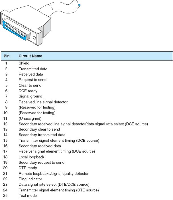
FIGURE A.1 RS232 cable specifications. DCE = data circuit terminating equipment; DTE = data terminal equipment
The RS232 has a maximum 50-foot cable length, but it can be increased to 100 feet or more by means of a special low-capacitance, extended-distance cable. This is not advised, however, because some vendors may not honor maintenance agreements if the cable is lengthened beyond the 50-foot standard.
In illustration, we present the cable distances for Texas Instruments’ products. The cable length of the RS232 varies according to the speed at which you transmit. For Texas Instruments, the connector cable length can be up to 914 meters (1 meter = 1.1 yards) when transmitting at 1,200 bps, 549 meters when transmitting at 2,400 bps, 244 meters when transmitting at 4,800 bps, and 122 meters when transmitting at 9,600 bps. When end users operate equipment at maximum distances, it is important to remember that they must meet the restrictions on all types of equipment used, including the electrical environment, cable construction, and cable wiring. This means that when you want to operate at a maximum cable distance, you must contact the computer and/or modem vendors to obtain their maximum cable distance before you proceed.
The RS449 standard has been adopted as U.S. Federal Standard 1031. The RS449 is shown in Figure A.2. A 4,000-foot cable length can be used, there are 37 pins instead of 25 (useful for digital transmission), and various other circuit functions have been added, such as diagnostic circuits and digital circuits. In addition, secondary channel circuits (reverse channel) have been put into a separate 9-pin connector known as a DB-9. The serial port on your microcomputer may be either a DB-9 or a DB-25.
For some of the new features, look at pin 32 (Select standby). With this pin, the terminal can instruct the modem to use an alternate standby network such as changing from a private leased line to a public packet network, either for backup or simply to access another database not normally used. In other words, a terminal can be connected to two different networks, and the operator can enter a keyboard command to switch the connection from one network to another. With regard to loopback pins 10 and 14, the terminal can allow basic tests without special test equipment or the manual exchanging of equipment or cables.
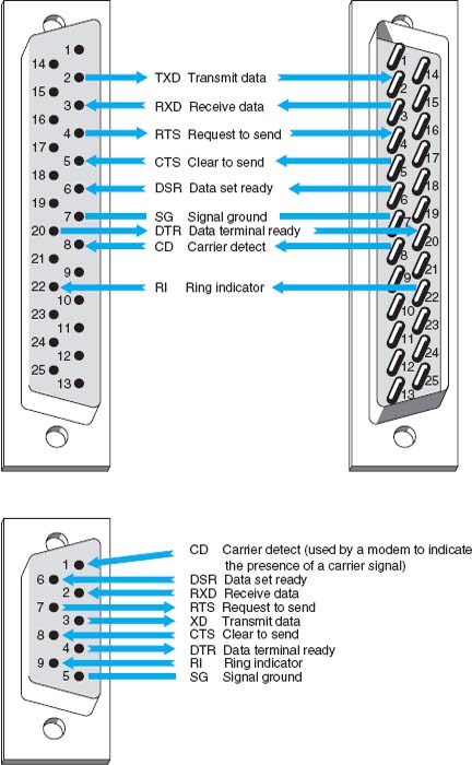
With microcomputers, the RS232 and RS449 also are referred to as D-type connectors. As stated above, the RS232 may be called a DB-25, and the 9-pin RS449 may be called a DB-9. Look at Figure A.3 to see the computer pin configurations for these two connectors.
There are also X.20 and X.21 interface cables. The X. 20 interface is for asynchronous communications, and the X.21 is for synchronous communications. Each is based on only 15 pins (wires) connecting the DTE and the DCE; the presence of fewer pins requires an increased intelligence in both the DTE and the DCE. X.20 and X.21 are international standards intended to provide an interface with the X.25 packet switching networks discussed elsewhere in this book.
Another option that may become available in the near future is a fiber-optic cable in place of the standard RS232 electrical cables. Currently, by using fiber-optic cable, we can locate a computer 1,000 meters (3,280 feet) from a server. With a 1,000-meter fiber-optic cable, these products can communicate at speeds ranging from 19,200 bps to twice that speed. Therefore, you get not only greater distance (1,000 meters) but also greater speed. This may be another example in which fiber optics eventually will replace electronics.
The high-speed serial interface (HSSI) is beginning to appear in new products. HSSI defines the physical and electrical interface between the DTE and the DCE equipment. It was developed by Cisco Systems of Menlo Park, California, and T3plus of Santa Clara, California. They have submitted it to the American National Standards Institute, which also formalized the EIA-232 and V.35 standards. HSSI allows data transfers over the connector cable at 52 million bps, whereas RS-449 cannot handle more than 10 million bps. HSSI is a 50-pin connector using shielded twisted-pair cabling.
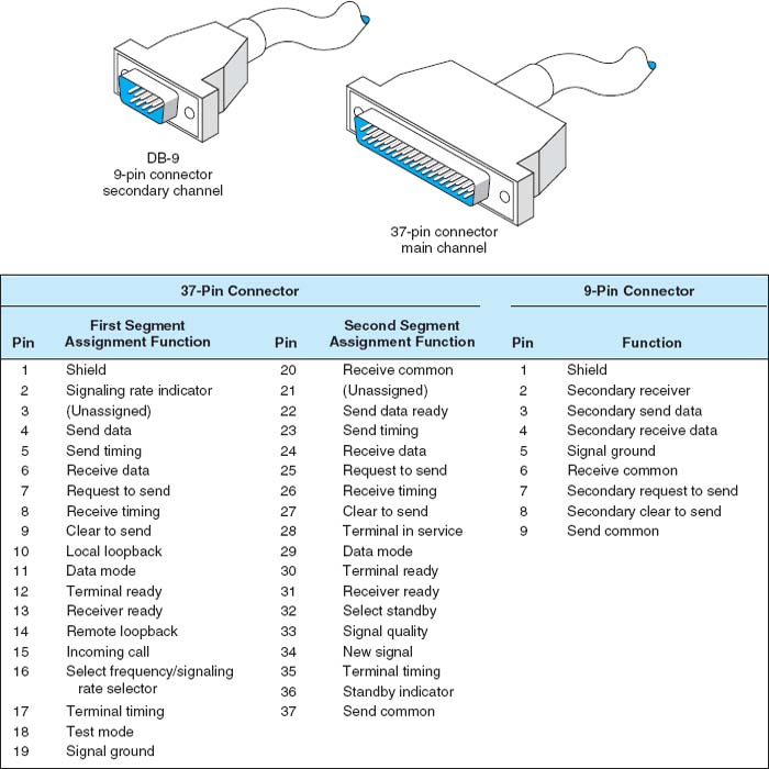
FIGURE A.2 RS449 cable specifications
A.2 NULL MODEM CABLE CONNECTIONS
Null modem cables allow transmission between two computers that are next to each other (6 to 8 feet apart) without using a modem. If you discover that the diskette from your computer will not fit into another one, that transmitting over telephone lines is impossible, or that you cannot transmit data easily from one computer to another for any reason, then it is time to get a null modem cable.
First, bring the two computers close together. Next, obtain a null modem cable (more on the pin connections shortly). The cable runs from the serial communication port on the first computer to the serial communication port on the second one. The cable is called a null modem cable because it eliminates the need for a modem. You can either build a null modem cable or buy one from any computer store. Null modem connector blocks are available to connect between two cables you already own.
To transfer data between two computers, just hook the null modem cable between them and call up one of the computers by using the communication software you normally use. To do so, put one computer in answer mode and use the other one to call it, but skip the step of dialing the telephone number. After the receiving computer has answered that it is ready, the data can be sent, just as you would on a normal long-distance dial-up connection. Basically, a null modem cable switches pins 2 and 3 (Transmit and Receive) of the RS232 connector plug.
A.3 DATA SIGNALING/SYNCHRONIZATION
Let us look at data signaling or synchronization as it occurs on a RS232 connector cable. Figure A.4 shows the 13 most frequently used pins of the 25-pin RS232 connector cable. A computer is on the left side of the figure and a modem is on the right.
Do you ever wonder what happens when you press the “send” key to transmit synchronous data? When a synchronous block of data is sent, the computer and the modem raise and lower electrical signals (plus and minus polarity) between themselves over the RS232 connector. This is usually a nominal +12 or −12 volts. For example, a modem with a RS232 interface might indicate that it is on and ready to operate by raising the signal on pin 6, Data set ready. (Data set is an older term for a modem.) When a call comes in, the modem shows the computer that the telephone line is ringing by raising a signal on pin 22, the Ring indicator. Raising a signal means putting +12 volts on the wire or pin. The computer may then tell the modem to answer the call by raising a signal on pin 20, Data terminal ready. After the modems connect, the modem may indicate the connection status to the computer by raising a signal on pin 8, Carrier detect. At the end of the session, the microcomputer may tell the modem to drop the telephone call (release the circuit) by lowering the signal on pin 20, Data terminal ready. The Request to send and Clear to send signals go over pins 4 and 5, respectively, which are used in half-duplex modems to manage control of the communication channel. Incidentally, some of these basic procedures may vary slightly from one manufacturer to another.
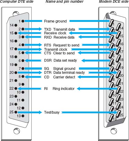
FIGURE A.4 Data signaling with RS232 cables. DCE 1-1-data circuit terminating equipment: DTE 1-1-data terminal equipment
Follow the pins and signal direction arrows in Figure A.4 as we discuss an example that handles the flow of a block of synchronous data. When the computer operator presses the “send” key to transmit a block of data, pin 4, Request to send, transmits the signal from the computer to the modem. This informs the modem that a block of data is ready to be sent. The modem then sends a Clear to send signal back to the computer by using pin 5, thus telling the computer that it can send a synchronous block of data.
The computer now outpulses a serial stream of bits that contain two 8-bit SYN characters in front of the message block. A SYN character is 0110100 (decimal 22 in ASCII code). This bit stream passes over the connector cable to the modem using pin 2, Transmit data. The modem then modulates this data block to convert it from the digital signal (plus and minus polarity) to an analog signal (discussed in the next section). From the modem, the data go out onto the local loop circuit between your business premises and the telephone company central office. From there, it goes to the long-distance IXC and the receiving end's telephone company central office. Then it moves to the local loop, into the modem, across the connector cable, and into the server at the other end of the circuit.
This process is repeated for each synchronous message block in half-duplex transmission. The data signaling that takes place between the computer and the modem involves the Request to send, Clear to send, and Transmit data pins. Accurate timing between blocks of data is critical in data signaling and synchronization. If this timing is lost, the entire block of data is destroyed and must be retransmitted.
A.4 ETHERNET AND RJ–45
A.4.1 10Base-T
Ethernet 10Base-T is most often wired with cat 5 cable, which has four pairs of wire in each cable, but only two pairs are used so that cat 3 cable can still be used if desired. One pair of two wires is used to transmit from the computer to the hub (or switch), while the other pair of two wires is used to receive data from the hub (or switch). Both wires in each pair transmit the same signal but with opposite polarity; the transmit + wire uses positive charges while the transmit—uses negative charges. This redundancy helps reduce errors and also reduces interference between the wires in the pair. Thus, 10Base-T is capable of full-duplex transmission at the hardware level, but it usually is only implemented as half-duplex.
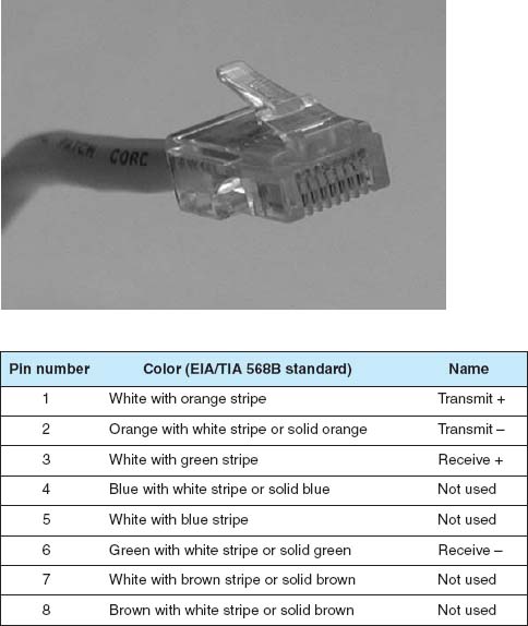
FIGURE A.5 Pins used by 10Base-T and 100Base-T at the computer end
Figure A.5 shows the way in which cat 5 cables are wired. The cable is wired into an RJ–45 connector,1 which is an 8-pin connector used to plug into NICs, hubs, and switches. Pins 1 and 2 are the wires used to transmit from the computer's NIC while pins 3 and 6 are used to receive transmissions at the computer's NIC. The pins on the hub or switch are reversed; that is, pins 1 and 2 deliver the computer's NIC's transmissions, so they are the receive pins at the hub or switch, while 3 and 6 are the receive pins at the hub or switch. Any time you want to directly connect two computer NICs or two hubs/switches, you must use a crossover cable, which connects pins 1 and 2 at one end to pins 3 and 6 at the other (and vice versa).
In order to successfully send and receive messages, both the sender and receiver have to agree how bits will be transmitted over the specific wires in the cable. They must understand both how fast the data will be sent and what electrical voltages will be used to represent a binary 1 and a binary 0. 10Base-T transmits at a rate of 10 Mbps, or 10 million bits per second. This means that the computers divide each second into 10 million time periods in which they can send data. Each time period (100nanoseconds [i.e., 100 billionths of a second]) contains one bit, either binary 1 or a binary 0. Thus each wire in the cat 3 or cat 5 cable must be capable of carrying a signal that changes 10 million times per second; we call this a signaling rate of 10 million Hertz, or 10 MHz.
One of the challenges in transmitting this fast is making sure that the clock at the receiver is synchronized with the clock at the sender so they can both understand when one of these 100-nanosecond time periods starts and stops. This is done by using Manchester encoding, a special type of signaling in which the signal is changed from high voltage (2 volts) to low voltage (0 volts) or vice versa in the middle of the signal. A change from low to high is used to represent a 1, while the opposite (a change from high to low) is used to represent a 0. Thus, in the exact middle of each time period, the signal voltage changes. This “heartbeat” synchronizes the clocks.
A.4.2 100Base-T
Ethernet 100Base-T also transmits data over cat 5 cables. It uses exactly the same wiring and connector pin configurations as 10Base-T so that the wiring for the two types of LANs is identical.
100Base-T does not use Manchester encoding. 100Base-T uses 4B5B coding, in which the data are sent in groups of 5 bits, the first 4 of which are data and the last one is used for clock synchronizing purposes and to minimize interference. The fifth bit is chosen to ensure than no more than 4 out of the 5 bits have the same value. Because of the high speed at which the data is being transmitted, a long series of all ones or all zeros would result in a long transmission of positive or negative voltage, which has a greater chance of causing interference to other wires than an alternating positive and negative pattern of voltages. Also, without regular changes in signal as is done in Manchester encoding, it becomes increasingly difficult to ensure that the clocks on the sender and receiver are synchronized. Adding this extra fifth bit every 4 bits of data ensures no long single-level transmissions are sent and ensures a transition for clock synchronizing.
In order to achieve a data rate of 100 Mbps when using 4B5B, the sender and receiver have to operate at 125 MHz, because only 4 out of every 5 bits transmitted contain data. 100Base-T uses a technique called Multi-Level Transmission–3 Level (MLT-3) to transmit the 4B5B codes through the cable. With MLT-3, three levels of voltage are defined, +1 volts, 0 volts, and −1 volts. MLT-3 is based on changes in voltages like Manchester encoding, but in a different way. To send a binary zero, MLT-3 simply maintains the same voltage as used in the previous time slot. To transmit a binary 0, the voltage is changed to an adjacent level (e.g., from −1 to 0 or 0 to +1).
A.4.3 1 GbE
The version of 1 GbE that runs over twisted-pair cables is called 1000Base-T and runs over one cat 5 cable by using parallel transmission. That is, it uses each of the four pairs of wires in the cat 5 cable as a separate half-duplex circuit with a transmit and receive wire pair. We now have four parallel circuits running through one cable, so in each clock tick we can send four signals at a time through the cable. 100Base-T Ethernet uses a 4B5B coding scheme in which the set of 5 bits (4 data, one overhead) were transmitted at 125 MHz (i.e., 125 million times per second), giving a speed of 100 Mbps. 125 MHz is the fastest data rate at which the wires in cat 5 can reliably transmit for any reasonable distance. However, 125 MHz times 4 bits per signal equals only 500 Mbps. In order to get 1000 Mbps, we have to do something more creative.
Until now, we talked about transmitting one bit in each time interval by using a higher voltage and a lower voltage (e.g., see Manchester encoding). Gigabit Ethernet uses the same 125 MHz clock speed as 100Base-T Ethernet, but sends 2 bits in each time interval using Pulse Amplitude Modulation–5 (PAM-5). With PAM-5, five different voltage levels are defined, ranging from +1 volts to −1 volts. Four of these voltage levels are used to send data. One voltage is defined to be the 2-bit pattern 00, another is defined to be 01, another 10, and another 11. The fifth voltage level is used for the fifth control bit. So, in each time period, the sender sends one electrical pulse at one of the five defined voltages, which represents a certain pattern of 2 bits, rather than just 1 bit as with Manchester encoding. Two bits per time interval times 125 time intervals per second times four separate circuit pairs in each cat 5 cable equals 1000 Mbps.
Because we are now sending 2 bits per signal using five different voltage levels rather than just two voltage levels as with Manchester encoding or 4B5B, the signal is more susceptible to noise or interference. This is because it is more difficult for the NIC to distinguish among differences in five voltage levels rather than two voltage levels because the differences between levels are smaller. It takes a much smaller amount of noise to trick the NIC into thinking a signal sent at one voltage level is actually a different level. For this reason, most organizations use cat 5e cable for 100Base-T; cat 5e is a version of cat 5 cable specially modified to reduce errors when used in 1000Base-T installations. Cat 6 cable has also been proposed, which has a capacity of 250 MHz. The maximum length of cat 5/5e/6 cable for 1000Base-T is 100 meters from the computer to the hub or switch.
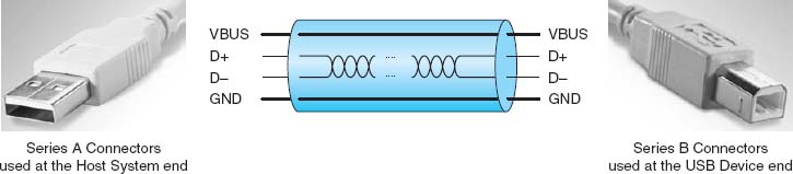
A.5 UNIVERSAL SERIAL BUS
Universal Serial Bus (USB) is another commonly used data transfer standard. Older USB devices will support serial data transfer at either 1.5 Mbps or 12 Mbps. Devices that conform to the USB 2.0 standard will support both these older speeds, plus 480 Mbps, which is sometimes called Hi-Speed USB.
USB cables have a host end and a device end, each of which have different styles of connectors (Figure A.6). Inside the cable, there are four wires. One is a ground wire and one (VBUS) is used to send a +5 volt power signal to the USB device. The two D wires are used to transmit the data in two separate serial data streams using a nonreturn to zero technique. The D+ wire sends the data with a positive charge while the D-wire sends the identical data with an offsetting negative charge to reduce interference and error.
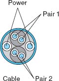
A.6 FIREWIRE
Firewire, a competitor to USB, was originally developed by Apple computer in the early 1990s and was standardized as IEEE 1394a-2000. Like USB, it is a serial bus connector. Firewire is also called i.Link.
Modern 1394a-2000 Firewire devices will support serial data transfer at 400 Mbps. Firewire cables have either a 4-pin or 6-pin configuration with a variety of different types of connectors. Inside the cable there are six wires (Figure A.7). Two are used to send 8–40 volts of power to the Firewire device. The other wires are two pairs of two wires used to transmit the data in two separate serial data streams using a nonreturn to zero technique. Within each pair, the D+ wire sends the data with a positive charge while the D- wire sends the identical data with an offsetting negative charge to reduce interference and error.
Because there are two pairs of wires, Firewire could be configured to transmit in parallel, but it is not. Instead, one pair of wires is used to send data and the other pair is used to continuously send clocking signals to minimize the chance of error.
1To be very precise, it is not an RJ-45 connector, but rather a version of the RJ-45 designed for network use. The RJ-45 is designed for telephone use, which tolerates higher interference. Just about everyone calls it an RJ-45 connector, but if you ever buy a “real” RJ-45 connector designed for telephone use and try to build a LAN cable yourself to save a few dollars, it won't work.