
APPENDIX B
SPANNING TREE PROTOCOL
Redundancy is an important element of good network design (see Chapter 12). Redundant circuits and devices mean that the network can continue to operate even if one circuit or device fails. For example, if a device has a 99.99 percent reliability, there is a.01 percent chance of failing. This means on average that the device will fail for about one hour per year. With two devices, the reliability increases to 99.9999 percent, or less than one minute of expected downtime per year.
Figure B.1 shows a common redundant network design. Two LAN segments (LAN 1 and LAN 2) are connected to two separate switches (A and B), that are in turn connected to two separate routers (X and Y) connected to the corporate WAN. Each switch has 4 ports; port 1 on switch A connects to LAN 1, port 2 connects to LAN 2, port 3 connects to router X, and port 4 connects to router Y. In this way, both LAN 1 and LAN 2 can continue to operate and send messages to and from each other and the WAN if any one circuit or device fails. For example, if switch A fails, all traffic into LAN 1 can still flow through switch B. Likewise, if router X fails, if the circuit from switch A to router X fails, or if port 3 on switch A fails, then traffic can flow through switch A to router Y and then into the WAN.
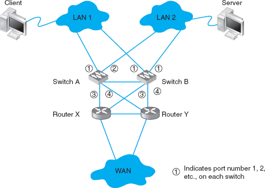
FIGURE B.1 Network design with redundant circuits and devices. LAN = local area network; WAN = wide area network
The challenge with redundant designs is to prevent broadcast storms. Remember that when switches are first turned on, they act like bridges, sending all messages in all directions, until they learn which device can be reached through which port (see Chapter 6). This means, for example, when the network in Figure B.1 is first turned on, neither switch A nor switch B will know where any device is. Assume that the client computer wants to send a message to the server. The message will enter LAN 1 from the client computer and be sent to switch A via the circuit connected to switch A's port 1. Switch A will learn that the client is on port 1. It won't know where the server is, so it will forward the packet on all remaining ports (2, 3, and 4). Router X on port 3 and router Y on port 4 will read the Ethernet address and ignore the message because it is not addressed to them. Eventually, the message will reach the server on LAN 2 via the message sent on port 2. The server will receive the message and send a response message to the client. The response message will hit switch A on port 2 (switch A will learn that the server is on port 2) and it will forward the response message to the client via port 1.
So far, so good. Now the problems start. Switch B is also on LAN 1, so it too will receive the very first message sent by the client, and will do exactly the same thing as switch A: it will learn that the client is on its port 1, and forward the message on its ports 2, 3, and 4. Once again, routers X and Y will ignore the message because it is not addressed to them (although the duplicate message has used up some of their processing capacity needlessly). When the message is sent to LAN 2 via port 2, the server sees it and starts to process it; we now have a duplicate message being processed twice.
But it gets worse. Switch A is also on LAN 2, so it receives all messages sent on LAN 2. When switch B sends the message from the client to the server into LAN 2, switch A also receives it, this time on its port 2. It now learns that the client is on port 2 (not port 1 as it originally thought; it assumes the computer has moved and updates its forwarding table), and promptly forwards the message a second time to the server on all remaining ports (1, 3, and 4). Routers X and Y see the message a third time and ignore it, but because switch B is also on LAN 1, it picks up the message again, thinks it is a new message, and again transmits the message on all other ports, which, of course, means that switch A gets the message again and forwards it again, and therefore switch B gets it again and forwards it, and so on, in a never-ending cycle. The same thing happens with the response message from the server to the client, and in fact, with all messages. They circulate forever through the circular loops in the redundant network, until the network collapses under the storm.1
The solution is to have switches configured with these redundant physical loops, but to create a way for the switches to recognize these physical loops and block them so that we create a different logical topology that does not have a loop. The method used to create this logical topology is called the spanning tree protocol and has been standardized as IEEE 802.1D.
With the spanning tree protocol, one switch is designated the root node or root switch. The cost to reach every computer, switch, or other device on the network from the root switch is calculated based on the “cost” of the intervening circuits (a 10 GbE circuit costs 2, 1 GbE costs 4, 100Base-T costs 19, and 10Base-T costs 100). The switches calculate the cost from the root switch to every device by sending information on the circuits they have to the switches around them using a special control message called a Bridge Protocol Data Unit (BPDU). 2 Switches send BPDUs every 2 seconds so that the network can quickly learn the logical topology and adjust to changes (e.g., if a circuit fails).
Once the switches determine the cost to reach other devices, they select one port as the designated port for each device and block all the other ports so that all messages to any one device use only the designated port. For example, in Figure B.1, switch A can reach the client via port 1 through one circuit. If all the circuits in the figure are 100Base-T, then the cost from switch A to the client via port 1 is 19. Switch A can also reach the client via port 2 through three circuits at a cost of 57 (to LAN 2, to switch B, to LAN 1). Ports 3 and 4 do not reach the client. Port 1 has the lowest cost, so it becomes the designated port for the client, and ports 2, 3, and 4 are marked as blocked for all traffic to the client (a blocked port is also called a discarding port). Likewise, switch A's port 2 is the designated port for traffic to the server (and ports 1, 3, and 4 are blocked for traffic to the server).
A switch only listens, learns, and forwards packets it receives on a designated port. In some cases, the network will change or a circuit may go down, meaning that the switch needs to be able to move from blocking a port to marking it as the designated port. If a circuit or device goes down, a switch can recognize it from the changes in the BPDUs it receives from the other switches in the network (or from the failure to receive BPDUs on that port). When a switch realizes that a designated port no longer reaches the target destination (or the cost has suddenly increased), then it recalculates the costs and designates a new port.
One challenge is to determine how fast a switch should alter its designated port. If the time is set too short, then loops may develop and the network becomes unstable. If time is too long, then the network takes too long to respond to problems and users experience delays. In the original version of the spanning tree standard (IEEE 802.1D), switches were set to take 50 seconds to change designated ports. Because networks are more reliable today and they are less likely to lose BPDUs unless a circuit goes down, the newer version of spanning tree standard (IEEE 802.1 w) waits only 15 seconds.
When a switch first starts up, it does not know the cost to any devices, to what devices it is connected, which ports should be designated and blocked, or which switch is the root switch. It must learn all of these. The switch starts by presuming that it is the root switch and sending out BPDUs on all ports. These BPDUs identify the switch and start by assuming a cost of 32,768 to reach other devices (i.e., that the distance is very far). If there are no other switches, then it remains the root switch (although because there are no other switches, there is no redundancy and spanning tree is not needed).
If there are other switches in the network, then the switch starts receiving BPDUs from the switches around it and starts updating its cost table. Gradually the artificially high costs are replaced by actual ones and the switch is able to build an accurate forwarding table and determine whether or not it is the root node.
1You may recall that an IP packet has a maximum hop count (also called time to live) to prevent this endless looping (see Chapter 5). Switches operate at the data link layer and therefore do not read the IP packet; the maximum hop count won't prevent looping at this layer.
2The spanning tree protocol was originally developed to be used by bridges and other layer-2 devices. Today, bridges are almost obsolete, so you are more likely to see spanning tree in a switched environment, but the terminology still reflects the origin with bridges.