Chapter 5. Wireless LAN Design
This chapter covers the following subjects:
Cisco Unified Wireless Network
Wireless LAN Design
Wireless LANs (WLANs) allow users to connect to network resources and services without using cables. With WLANs, users connect to the network in common areas, away from their desk, and in areas that do not easily accommodate the installation of wired cabling, such as outdoors and in designated historical sites. This chapter describes WLAN technologies, design, and Cisco solutions.
“Do I Know This Already?” Quiz
The “Do I Know This Already?” quiz helps you identify your strengths and deficiencies in this chapter’s topics.
The eight-question quiz, derived from the major sections in the “Foundation Topics” portion of the chapter, helps you determine how to spend your limited study time.
Table 5-1 outlines the major topics discussed in this chapter and the “Do I Know This Already?” quiz questions that correspond to those topics.

1. What technology provides 1.3 Gbps of bandwidth using 5GHz frequencies?
a. IEEE 802.11b
b. IEEE 802.11g
c. IEEE 802.11n
d. IEEE 802.11ac
2. What frequency allotment provides 11 channels for unlicensed use for WLANs in North America?
a. UNII
b. ISM
c. Bluetooth
d. FM
3. What standard is used for control messaging between access points and controllers?
a. IEEE 802.11
b. CSMA/CA
c. IEEE 802.1X
d. CAPWAP
4. Which WLAN controller interface is used for out-of-band management?
a. Management interface
b. Service-port interface
c. AP manager interface
d. Virtual interface
5. How many access points are supported by a Cisco WiSM WLC module?
a. 6
b. 50
c. 100
d. 1000
6. Which WLAN controller redundancy scheme uses a backup WLC configured as the tertiary WLC in the APs?
a. N+1
b. N+N
c. N+N+1
d. N+N+B
7. What is the recommended maximum number of data devices associated to a WLAN?
a. 8
b. 20
c. 50
d. 100
8. Which device of Cisco’s Wireless Mesh Networking communicates with the rooftop AP (RAP)?
a. WLC
b. WCS
c. RAP
d. MAP
Foundation Topics
Cisco has developed a strategy to address the increasing wireless demands placed on today’s networks. The Cisco Unified Wireless Network (UWN) architecture combines elements of wireless and wired networks to deliver scalable, manageable, and secure WLANs. Control and Provisioning for Wireless Access Point (CAPWAP) allows the placement of lightweight access points (LAPs) that are remotely configured and easily deployable versus them being manually configured on autonomous APs. Cisco provides solutions for client roaming, radio frequency management, and controller designs that make wireless networks scalable. This chapter covers the Cisco UWN architecture and general WLAN technologies and design.
Wireless LAN Technologies
This section reviews the Institute of Electronics and Electrical Engineers (IEEE) 802.11 WLAN standards, WLAN frequencies, access methods, security, and authentication.
WLAN Standards

WLAN applications include inside-building access, LAN extension, outside building-to-building communications, public access, and small office/home office (SOHO) communications. The first standard for WLANs was IEEE 802.11, approved by the IEEE in 1997. The current specification is IEEE 802.11-1999, with many amendments thereafter.
IEEE 802.11 implemented WLANs at speeds of 1 Mbps and 2 Mbps using direct sequence spread spectrum (DSSS) and frequency-hopping spread spectrum (FHSS) at the physical layer of the Open Systems Interconnection (OSI) model. DSSS divides data into separate sections; each section travels over different frequencies at the same time. FHSS uses a frequency-hopping sequence to send data in bursts. With FHSS, some data transmits at Frequency 1, and then the system hops to Frequency 2 to send more data, and so on, returning to transmit more data at Frequency 1. The interoperability certification for IEEE 802.11 WLANs is wireless fidelity (Wi-Fi). The Wireless Ethernet Compatibility Alliance (WECA) governs the Wi-Fi certification.
In 1999, the 802.11b amendment was introduced, providing an 11Mbps data rate. It provides speeds of 11, 5.5, 2, and 1 Mbps and uses 11 channels of the Industrial, Scientific, and Medical (ISM) frequencies. IEEE 802.11b uses DSSS and is backward compatible with 802.11 systems that use DSSS.
The IEEE approved a second standard in 1999. IEEE 802.11a provides a maximum 54Mbps data rate but is incompatible with 802.11b. It provides speeds of 54, 48, 36, 24, 18, 12, 9, and 6 Mbps. IEEE 802.11a uses 13 channels of the Unlicensed National Information Infrastructure (UNII) frequencies and is incompatible with 802.11b and 802.11g. IEEE 802.11a is also known as WiFi5.
In 2003, the IEEE 802.11g standard was approved, providing a 54Mbps data rate using the ISM frequencies. The advantage of 802.11g over 802.11a is that it is backward compatible with 802.11b.
The IEEE 802.11n standard was ratified in 2009. It added multiple-input multiple-output (MIMO) antennas and expected maximum data rates up to 600 Mbps using four spatial streams, each with a 40MHz width. In addition to DSSS, it uses orthogonal frequency-division multiplexing (OFDM) as a digital carrier modulation method. IEEE 802.11n uses both the 2.4GHz and 5GHz bands.
The latest wireless standard is IEEE 802.11ac, ratified in 2013. It comes in two waves. The first, 802.11ac Wave 1, provides improvements over 802.11n, with greater channel bonding at 80 MHz, up to eight MIMO single-user spatial streams, and denser modulation using 256 quadrature amplitude modulation (QAM; up from 64 QAM). The PHY rate for 802.11ac Wave 1 is 1.3 Gbps.
The second wave for 802.11ac includes the following features:
![]() Support for multiuser multiple-input, multiple-output (MU-MIMO)
Support for multiuser multiple-input, multiple-output (MU-MIMO)
![]() Support for speeds up to 2.34 Gbps
Support for speeds up to 2.34 Gbps
![]() 160MHz channel width
160MHz channel width
![]() 256 QAM modulation
256 QAM modulation
![]() Four spatial streams
Four spatial streams
![]() PHY rate of 2.34 to 3.47 Gbps
PHY rate of 2.34 to 3.47 Gbps
ISM and UNII Frequencies
ISM frequencies are set aside by ITU-R radio regulations 5.138 and 5.150. In the United States, the Federal Communications Commission (15.247) specifies the ISM bands for unlicensed use. ISM bands are specified in the following ranges:
![]() 900 MHz to 928 MHz
900 MHz to 928 MHz
![]() 2.4 GHz to 2.5 GHz
2.4 GHz to 2.5 GHz
![]() 5.75 GHz to 5.875 GHz
5.75 GHz to 5.875 GHz
Of these, channels located in the 2.4GHz range are used for 802.11b and 802.11g. As shown in Figure 5-1, 11 overlapping channels are available for use. Each channel is 22 MHz wide. It is common to use channels 1, 6, and 11 in the same areas because these three channels do not overlap.

The UNII radio bands were initially specified for use with 802.11a wireless, but are also used by 802.11n and 802.11ac. UNII operates over three ranges:
![]() UNII 1: 5.150 GHz to 5.250 GHz.
UNII 1: 5.150 GHz to 5.250 GHz.
![]() UNII 2: 5.230 GHz to 5.350 GHz and 5.470 GHz to 5.725 GHz.
UNII 2: 5.230 GHz to 5.350 GHz and 5.470 GHz to 5.725 GHz.
![]() UNII 3: 5.725 GHz to 5.875 GHz. This range overlaps with ISM.
UNII 3: 5.725 GHz to 5.875 GHz. This range overlaps with ISM.
UNII provides 12 nonoverlapping channels.
Summary of WLAN Standards
Table 5-2 summarizes the WLAN standards, frequencies, and data rates.

Service Set Identifier
WLANs use a service set identifier (SSID) to identify the WLAN’s “network name.” The SSID can be 2 to 32 characters long. The network engineer will then map the wireless SSID to a VLAN. All devices in the WLAN must have the same configured SSID to communicate. It is similar to a VLAN identifier in a wired network. The difficulty in large networks is in configuring the SSID, frequency, and power settings for hundreds of remotely located access points. Cisco addresses this problem with the Cisco Wireless Control System (WCS), which allows the network engineer to manage thousands of APs from a single controller. WCS is covered in more detail in the “Cisco UWN Architecture” section.
A single AP can broadcast multiple SSIDs simultaneously. Each of the SSIDs should get mapped to its own VLAN and IP subnets. Based on the purpose of the wireless network, different SSIDs will get different security and access to different parts of the network. Many companies implement “guest” SSIDs to allow visitors basic access to the Internet. Internal corporate SSIDs will have stronger security and authentication before allowing the user access to corporate internal resources. Table 5-3 provides a basic example of SSIDs and mappings.

WLAN Layer 2 Access Method
The IEEE 802.11 Media Access Control (MAC) layer implements carrier sense multiple access with collision avoidance (CSMA/CA) as an access method. With CSMA/CA, each WLAN station listens to see whether a station is transmitting. If no activity is occurring, the station transmits. If activity is occurring, the station uses a random countdown timer. When the timer expires, the station transmits. The difference from wired networks is that in wired networks, collisions are detected on the physical wire; hence, CSMA/CD (collision detection) is used.
WLAN Security
WLANs provide an effective solution for hard-to-reach locations and enable mobility to a level that was previously unattainable. However, the reach of wireless beyond physical connections and boundaries presents additional security concerns. Several standards have been developed to address these security concerns. The Wired Equivalent Privacy (WEP) security protocol, used in the IEEE 802.11b standard, is considered faulty and vulnerable to numerous attacks.
In June 2004, the IEEE 802.11i standard was ratified to provide additional security in WLAN networks. It supersedes WEP security, and introduces the 4-way Handshake and the Group Key Handshake. IEEE 802.11i is also known as Wi-Fi Protected Access 2 (WPA2) and Robust Security Network (RSN). The 802.11i architecture contains the following components:
![]() 4-way Handshake and Group Key Handshake: Both use 802.1X for authentication, thus entailing the use of Extensible Authentication Protocol (EAP) and an authentication server.
4-way Handshake and Group Key Handshake: Both use 802.1X for authentication, thus entailing the use of Extensible Authentication Protocol (EAP) and an authentication server.
![]() Robust Security Network (RSN): Used for the establishment and tracking of robust security network associations.
Robust Security Network (RSN): Used for the establishment and tracking of robust security network associations.
![]() Advanced Encryption Standard (AES): Used for confidentiality, integrity, and origin authentication.
Advanced Encryption Standard (AES): Used for confidentiality, integrity, and origin authentication.
Unauthorized Access
A problem that confronts WLANs comes from the fact that wireless signals are not easily controlled or contained. WEP works at the data link layer, sharing the same key for all nodes that communicate. The 802.11 standard was deployed because it allows bandwidth speed up to 11 Mbps and it is based on DSSS technology. DSSS also enables APs to identify WLAN cards via their MAC addresses. Because traditional physical boundaries do not apply to wireless networks, attackers can gain access using wireless from outside the physical security perimeter. Attackers achieve unauthorized access if the wireless network does not have a mechanism to compare a MAC address on a wireless card to a database that contains a directory with access rights. An individual can roam within an area, and each AP that comes into contact with that card must also rely on a directory. Statically allowing access via a MAC address is also unsecure because MAC addresses can be spoofed.
Some APs can implement MAC address and protocol filtering to enhance security or limit the protocols used over the WLAN. With hundreds of WLAN clients, MAC address filtering is not a scalable solution. Again, attackers can hack MAC address filtering. A user can listen for transmissions, gather a list of MAC addresses, and then use one of those MAC addresses to connect to the AP. This is why additional security protocols such as WEP, WPA, and WPA2 have to be implemented so that the attacker has to attempt to crack the security keys to gain access.
WLAN Security Design Approach
The WLAN security design approach makes two assumptions, which this chapter describes. The assumptions are that all WLAN devices are connected to a unique IP subnet and that most services available to the wired network are also available to the wireless nodes. Using these two assumptions, the WLAN security designs offer two basic security approaches:
![]() Use of EAP-Flexible Authentication via Secure Tunneling (EAP-FAST) to secure authentication
Use of EAP-Flexible Authentication via Secure Tunneling (EAP-FAST) to secure authentication
![]() Use of virtual private networks (VPNs) with IP Security (IPsec) to secure traffic from the WLAN to the wired network
Use of virtual private networks (VPNs) with IP Security (IPsec) to secure traffic from the WLAN to the wired network
Considering WLAN as an alternative access methodology, remember that the services these WLAN users access are often the same as those accessed by the wired users. WLANs potentially open many new attack vectors for hackers, and you should consider the risks before deployment.
To enhance security, you can implement WLANs with IPsec VPN software, use the IEEE 802.1X-2001 port-based access control protocol, and use WPA.
IEEE 802.1X-2001 Port-Based Authentication
IEEE 802.1X-2001 is a port-based authentication standard for LANs. It authenticates a user before allowing access to the network. You can use it on Ethernet, Fast Ethernet, and WLAN networks.
With IEEE 802.1X-2001, client workstations run client software to request access to services. Clients use EAP to communicate with the LAN switch. The LAN switch verifies client information with the authentication server and relays the response to the client. LAN switches use a Remote Authentication Dial-In User Service (RADIUS) client to communicate with the server. The RADIUS authentication server validates the client’s identity and authorizes the client. But note that it does not provide encryption privacy. The server uses RADIUS with EAP extensions to make the authorization.
Dynamic WEP Keys and LEAP
Cisco also offers dynamic per-user, per-session WEP keys to provide additional security over statically configured WEP keys, which are not unique per user. For centralized user-based authentication, Cisco developed LEAP. LEAP uses mutual authentication between the client and the network server and uses IEEE 802.1X for 802.11 authentication messaging. LEAP can be used with the Temporal Key Integrity Protocol (TKIP) rather than WEP to overcome the weaknesses of WEP. LEAP uses a RADIUS server to manage user information.
LEAP is a combination of 802.1X and EAP. It combines the capability to authenticate to various servers such as RADIUS with forcing the WLAN user to log on to an access point that compares the logon information to RADIUS. This solution is more scalable than MAC address filtering.
Because the WLAN access depends on receiving an address, using Dynamic Host Configuration Protocol (DHCP), and the authentication of the user using RADIUS, the WLAN needs constant access to these back-end servers. In addition, LEAP does not support one-time passwords (OTPs), so you must use good password-security practices. The password issue and maintenance practice are a basic component of corporate security policy.
Controlling WLAN Access to Servers
In the same way you place Domain Name System (DNS) servers accessible via the Internet on a demilitarized zone (DMZ) segment, you should apply a similar strategy to the RADIUS and DHCP servers accessible to the WLAN. These servers should be secondary servers that are on a different segment (separate VLAN) from their primary counterparts. Access to this VLAN is filtered. Such placement ensures that any attacks launched on these servers are contained within that segment.
You should control network access to the servers. Consider the WLAN an unsecured segment and apply appropriate segmentation and access lists. Such a step ensures that WLAN access is controlled and directed to only those areas that need it. For example, you might not want to permit WLAN access to management servers and HR servers.
You must also protect these servers against network attack. The criticality of these servers makes them an ideal target for denial-of-service (DoS) attacks. Consider using network-based intrusion detection systems (IDSs) to detect network attacks against these devices.
Cisco Unified Wireless Network
This section covers the Cisco Unified Wireless Network (UWN) architecture, Control and Provisioning for Wireless Access Point (CAPWAP), WLAN controller components, roaming, and mobility groups. Cisco UWN components provide scalable WLAN solutions using WLAN controllers to manage lightweight access points (LAPs). The CCDA must understand how these components work with each other, how they scale, and how roaming and mobility groups work.
Cisco UWN Architecture
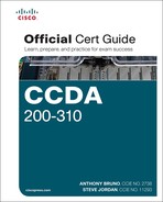
With the explosion of wireless solutions in and out of the enterprise, designers must create solutions that provide mobility and business services while maintaining network security. The Cisco UWN architecture combines elements of wireless and wired networks to deliver scalable, manageable, and secure WLANs. As shown in Figure 5-2, the Cisco UWN architecture is composed of five network elements:
![]() Client devices: These include laptops, workstations, IP phones, PDAs, and manufacturing devices to access the WLAN.
Client devices: These include laptops, workstations, IP phones, PDAs, and manufacturing devices to access the WLAN.
![]() Access points: These devices provide access to the wireless network. APs are placed in strategic locations to minimize interference.
Access points: These devices provide access to the wireless network. APs are placed in strategic locations to minimize interference.
![]() Network unification: The WLAN system should be able to support wireless applications by providing security policies, QoS, intrusion prevention, and radio frequency (RF) management. Cisco WLAN controllers provide this functionality and integration into all major switching and routing platforms.
Network unification: The WLAN system should be able to support wireless applications by providing security policies, QoS, intrusion prevention, and radio frequency (RF) management. Cisco WLAN controllers provide this functionality and integration into all major switching and routing platforms.
![]() Network management: The Cisco Wireless Control System (WCS) provides a central management tool that lets you design, control, and monitor wireless networks.
Network management: The Cisco Wireless Control System (WCS) provides a central management tool that lets you design, control, and monitor wireless networks.
![]() Mobility services: These include guest access, location services, voice services, and threat detection and mitigation.
Mobility services: These include guest access, location services, voice services, and threat detection and mitigation.

Cisco UWN provides the following benefits:
![]() Reduced total cost of ownership (TCO)
Reduced total cost of ownership (TCO)
![]() Enhanced visibility and control
Enhanced visibility and control
![]() Dynamic RF management
Dynamic RF management
![]() WLAN security
WLAN security
![]() Unified wired and wireless network
Unified wired and wireless network
![]() Enterprise mobility
Enterprise mobility
![]() Enhanced productivity and collaboration
Enhanced productivity and collaboration
Table 5-4 covers the Cisco UWN architecture.
Autonomous Access Points
Access points (APs) provide wireless access to client devices to the network. In older networks, APs were configured autonomously. Autonomous APs operate independently of each other and have to be individually configured. This method of configuration might be okay for small networks but would be very difficult to manage for hundreds and thousands of APs.
Centralized WLAN Architecture
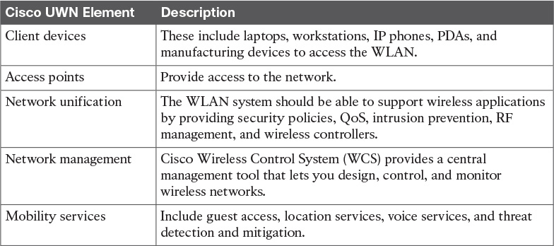
In the centralized WLAN architecture, autonomous APs are replaced by lightweight access points (LAPs). These LAPs are then configured and managed by a wireless LAN controller (WLC). Furthermore, user traffic is placed on the wired network at the controller and not at the LAP. As shown in Figure 5-3, wireless 802.11 traffic is placed in CAPWAP tunnels over the 802.3 wired network. Traffic then goes from the WLC to its IP destination.
LWAPP
Lightweight Access Point Protocol (LWAPP) is a Cisco standard for control messaging for setup, authentication, and operations between APs and WLAN controllers (WLCs). LWAPP has been deprecated in favor of CAPWAP.
LWAPP control messages can be transported at Layer 2 tunnels or Layer 3 tunnels. Layer 2 LWAPP tunnels were the first method developed in which the APs did not require an IP address. The disadvantage of Layer 2 LWAPP was that the WLC needed to be on every subnet on which the AP resides. Layer 2 LWAPP is a deprecated solution for Cisco. Layer 3 LWAPP was the preferred solution before CAPWAP. In the configuration, Layer 2 or Layer 3 transport modes can be selected. When set to Layer 3, the LWAPP uses IP addresses to communicate with the access points; these IP addresses are collected from a mandatory DHCP server. When set to Layer 2, the LWAPP uses proprietary code to communicate with the access points.
Note
Layer 2 LWAPP tunnels use EtherType code 0xBBBB. Layer 3 LWAPP uses UDP ports 12222 and 12223.
As shown in Figure 5-4, Layer 3 LWAPP tunnels are used between the LAP and the WLC. Messages from the WLC use User Datagram Port (UDP) port 12223 for control and UDP port 12222 for data messages. In this solution, APs require an IP address, but the WLC does not need to reside on the same segment.

CAPWAP
Control and Provisioning for Wireless Access Point (CAPWAP) is an IETF standard (RFC 5415) for control messaging for setup, authentication, and operations between APs and WLCs. In Controller Software 5.2, Cisco LAPs use CAPWAP communication between the WLC and LAPs. CAPWAP is similar to LWAPP, except for the following differences:
![]() CAPWAP uses Datagram Transport Layer Security (DTLS) for authentication and encryption to protect traffic between APs and controllers. LWAPP uses AES.
CAPWAP uses Datagram Transport Layer Security (DTLS) for authentication and encryption to protect traffic between APs and controllers. LWAPP uses AES.
![]() CAPWAP has a dynamic maximum transmission unit (MTU) discovery mechanism.
CAPWAP has a dynamic maximum transmission unit (MTU) discovery mechanism.
![]() CAPWAP control messages run over UDP 5246.
CAPWAP control messages run over UDP 5246.
![]() CAPWAP data messages use UDP 5247.
CAPWAP data messages use UDP 5247.
CAPWAP uses a Layer 3 tunnel between the LAP and the WLC. Figure 5-5 shows the architecture. The APs obtain an IP address via DHCP. On the AP side, the control and data messages use an ephemeral UDP port that is derived from a hash between the AP MAC addresses. CAPWAP uses UDP port 5247 for data messages and UDP port 5246 for control messages.

Cisco Unified Wireless Network Split-MAC Architecture
With the Cisco UWN split-MAC operation, the control and data messages are split. LAPs communicate with the WLCs using control messages over the wired network. LWAPP or CAPWAP data messages are encapsulated and forwarded to and from wireless clients. The WLC manages multiple APs, providing configuration information and firmware updates as needed.
LAP MAC functions are
![]() 802.11: Beacons, probe response
802.11: Beacons, probe response
![]() 802.11 Control: Packet acknowledgment and transmission
802.11 Control: Packet acknowledgment and transmission
![]() 802.11e: Frame queuing and packet prioritization
802.11e: Frame queuing and packet prioritization
![]() 802.11i: MAC layer data encryption/decryption
802.11i: MAC layer data encryption/decryption
Controller MAC functions are
![]() 802.11 MAC Management: Association requests and actions
802.11 MAC Management: Association requests and actions
![]() 802.11e Resource Reservation: To reserve resources for specific applications
802.11e Resource Reservation: To reserve resources for specific applications
![]() 802.11i: Authentication and key management
802.11i: Authentication and key management
Local MAC
CAPWAP supports local MAC. Local MAC moves the MAC management from the WLC to the local AP. This allows for termination of client traffic at the wired port of the AP. The functionality is useful for small and remote branch offices, which would not require a WLC.
LAP MAC functions are
![]() 802.11: Beacons, probe response
802.11: Beacons, probe response
![]() 802.11 Control: Packet acknowledgment and transmission
802.11 Control: Packet acknowledgment and transmission
![]() 802.11e: Frame queuing and packet prioritization
802.11e: Frame queuing and packet prioritization
![]() 802.11i: MAC layer data encryption/decryption
802.11i: MAC layer data encryption/decryption
![]() 802.11 MAC Management: Association requests and actions
802.11 MAC Management: Association requests and actions
Controller MAC functions are
![]() 802.11: Proxy association requests and actions
802.11: Proxy association requests and actions
![]() 802.11e Resource Reservation: To reserve resources for specific applications
802.11e Resource Reservation: To reserve resources for specific applications
![]() 802.11i: Authentication and key management
802.11i: Authentication and key management
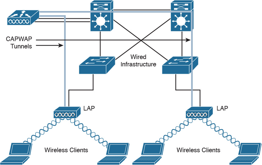
Figure 5-6 shows the difference between an autonomous AP and a CAPWAP using WLC. Autonomous APs act as a 802.1Q translational bridge with a trunk to the LAN switch. In CAPWAP with WLC, the AP uses a CAPWAP tunnel, and the WLC establishes the 802.1Q trunk to the LAN switch.
AP Modes
For the CCDA test, make sure you understand the different AP modes. APs operate in one of six different modes:
![]() Local mode: This is the default mode of operation. In this mode, every 180 seconds the AP measures noise floor and interference, and scans for IDS events. This scanning activity occurs on unused channels and lasts for 60 milliseconds.
Local mode: This is the default mode of operation. In this mode, every 180 seconds the AP measures noise floor and interference, and scans for IDS events. This scanning activity occurs on unused channels and lasts for 60 milliseconds.
![]() Hybrid Remote Edge AP (H-REAP) mode: This mode enables a LAP to reside across a WAN link and still be able to communicate with the WLC and provide the functionality of a regular LAP. It allows local MAC.
Hybrid Remote Edge AP (H-REAP) mode: This mode enables a LAP to reside across a WAN link and still be able to communicate with the WLC and provide the functionality of a regular LAP. It allows local MAC.
![]() Monitor mode: Monitor mode is a feature designed to allow specified CAPWAP-enabled APs to exclude themselves from handling data traffic between clients and the infrastructure. They instead act as dedicated sensors for location-based services (LBS), rogue AP detection, and intrusion detection (IDS). When APs are in Monitor mode, they cannot serve clients and continuously cycle through all configured channels, listening to each channel for approximately 60 ms.
Monitor mode: Monitor mode is a feature designed to allow specified CAPWAP-enabled APs to exclude themselves from handling data traffic between clients and the infrastructure. They instead act as dedicated sensors for location-based services (LBS), rogue AP detection, and intrusion detection (IDS). When APs are in Monitor mode, they cannot serve clients and continuously cycle through all configured channels, listening to each channel for approximately 60 ms.
![]() Rogue detector mode: LAPs that operate in Rogue Detector mode monitor for rogue APs. They do not transmit or contain rogue APs. The idea is that the rogue detector (RD) should be able to see all the VLANs in the network, because rogue APs can be connected to any of the VLANs in the network. (Therefore, we connect it to a trunk port.) The LAN switch sends all the rogue AP/client MAC address lists to the RD. The RD then forwards those to the WLC to compare with the MAC addresses of clients that the WLC APs have heard over the air. If the MAC addresses match, the WLC knows that the rogue AP to which those clients are connected is on the wired network.
Rogue detector mode: LAPs that operate in Rogue Detector mode monitor for rogue APs. They do not transmit or contain rogue APs. The idea is that the rogue detector (RD) should be able to see all the VLANs in the network, because rogue APs can be connected to any of the VLANs in the network. (Therefore, we connect it to a trunk port.) The LAN switch sends all the rogue AP/client MAC address lists to the RD. The RD then forwards those to the WLC to compare with the MAC addresses of clients that the WLC APs have heard over the air. If the MAC addresses match, the WLC knows that the rogue AP to which those clients are connected is on the wired network.
![]() Sniffer mode: A CAPWAP that operates in Sniffer mode functions as a sniffer and captures and forwards all the packets on a particular channel to a remote machine that runs AiroPeek. These packets contain information on the timestamp, signal strength, packet size, and so on. The Sniffer feature can be enabled only if you run AiroPeek, a third-party network analyzer software that supports decoding of data packets.
Sniffer mode: A CAPWAP that operates in Sniffer mode functions as a sniffer and captures and forwards all the packets on a particular channel to a remote machine that runs AiroPeek. These packets contain information on the timestamp, signal strength, packet size, and so on. The Sniffer feature can be enabled only if you run AiroPeek, a third-party network analyzer software that supports decoding of data packets.
![]() Bridge mode: Applications supported are point-to-point bridging, point-to-multipoint bridging, point-to-point wireless access with integrated wireless backhaul, and point-to-multipoint wireless access with integrated wireless backhaul.
Bridge mode: Applications supported are point-to-point bridging, point-to-multipoint bridging, point-to-point wireless access with integrated wireless backhaul, and point-to-multipoint wireless access with integrated wireless backhaul.
Table 5-5 summarizes the AP modes.

LAP Discovery of WLC Using CAPWAP
When LAPs are placed on the network, they first perform DHCP discovery to obtain an IP address.
For controllers that have a CAPWAP image, the AP follows the following process:
1. The CAPWAP AP starts the discovery process to find the controller by using a CAPWAP request. The WLC responds with a CAPWAP response.
2. If a CAPWAP response is not received after 60 seconds, the AP starts the discovery process using LWAPP discovery.
3. If the AP cannot find a controller using LWAPP within 60 seconds, it returns to step 1.
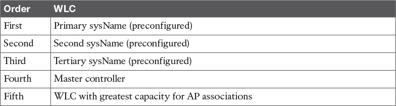
WLC selection by a CAPWAP is a design decision. This is configurable in the WLC. The AP selects the WLC to create a CAPWAP tunnel based on the information configured in the WLC. The WLC responses contain controller sysName, controller type, controller AP capacity and load, the master controller status, and the AP manager IP addresses. The AP selects one or several WLCs to send a CAPWAP tunnel request based on Table 5-6. The WLC validates the AP and sends a CAPWAP tunnel response, an encryption key is derived, and future messages are encrypted. The AP then selects one WLC and sends a join request.
WLAN Authentication
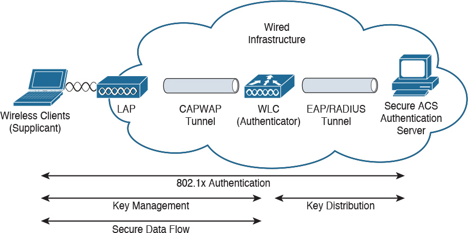
Wireless clients first associate to an AP. Then wireless clients need to authenticate with an authentication server before the AP allows access to services. As shown in Figure 5-7, the authentication server resides in the wired infrastructure. An EAP/RADIUS tunnel occurs between the WLC and the authentication server. Cisco’s Secure Access Control Server (ACS) using EAP is an example of an authentication server.
Authentication Options
Wireless clients communicate with the authentication server using EAP. Each EAP type has advantages and disadvantages. Trade-offs exist between the security provided, EAP type manageability, the operating systems supported, the client devices supported, the client software and authentication messaging overhead, certificate requirements, user ease of use, and WLAN infrastructure device support. The following summarizes the authentication options:
![]() EAP-Transport Layer Security (EAP-TLS) is an IETF open standard that is well supported among wireless vendors but rarely deployed. It uses Public Key Infrastructure (PKI) to secure communications to the RADIUS authentication server using TLS and digital certificates.
EAP-Transport Layer Security (EAP-TLS) is an IETF open standard that is well supported among wireless vendors but rarely deployed. It uses Public Key Infrastructure (PKI) to secure communications to the RADIUS authentication server using TLS and digital certificates.
![]() Protected Extensible Authentication Protocol (PEAP) is a joint proposal by Cisco Systems, Microsoft, and RSA Security as an open standard. PEAP/MSCHAPv2 is the most common version, and it is widely available in products and widely deployed. It is similar in design to EAP-TTLS, requiring only a server-side PKI certificate to create a secure TLS tunnel to protect user authentication. PEAP-GTC allows more generic authentication to a number of databases such as Novell Directory Services (NDS).
Protected Extensible Authentication Protocol (PEAP) is a joint proposal by Cisco Systems, Microsoft, and RSA Security as an open standard. PEAP/MSCHAPv2 is the most common version, and it is widely available in products and widely deployed. It is similar in design to EAP-TTLS, requiring only a server-side PKI certificate to create a secure TLS tunnel to protect user authentication. PEAP-GTC allows more generic authentication to a number of databases such as Novell Directory Services (NDS).
![]() EAP-Tunneled TLS (EAP-TTLS) was co-developed by Funk Software and Certicom. It is widely supported across platforms and offers good security, using PKI certificates only on the authentication server.
EAP-Tunneled TLS (EAP-TTLS) was co-developed by Funk Software and Certicom. It is widely supported across platforms and offers good security, using PKI certificates only on the authentication server.
![]() Cisco Lightweight Extensible Authentication Protocol (LEAP) is an early proprietary EAP method supported in the Cisco Certified Extensions (CCX) program. It is vulnerable to dictionary attacks.
Cisco Lightweight Extensible Authentication Protocol (LEAP) is an early proprietary EAP method supported in the Cisco Certified Extensions (CCX) program. It is vulnerable to dictionary attacks.
![]() EAP-Flexible Authentication via Secure Tunneling (EAP-FAST) is a proposal by Cisco Systems to fix the weaknesses of LEAP. EAP-FAST uses a Protected Access Credential (PAC), and use of server certificates is optional. EAP-FAST has three phases. Phase 0 is an optional phase in which the PAC can be provisioned manually or dynamically. In Phase 1, the client and the AAA server use the PAC to establish the TLS tunnel. In Phase 2, the client sends user information across the tunnel.
EAP-Flexible Authentication via Secure Tunneling (EAP-FAST) is a proposal by Cisco Systems to fix the weaknesses of LEAP. EAP-FAST uses a Protected Access Credential (PAC), and use of server certificates is optional. EAP-FAST has three phases. Phase 0 is an optional phase in which the PAC can be provisioned manually or dynamically. In Phase 1, the client and the AAA server use the PAC to establish the TLS tunnel. In Phase 2, the client sends user information across the tunnel.
WLAN Controller Components
The CCDA candidate must understand the three major components of WLCs:
![]() WLANs
WLANs
![]() Interfaces
Interfaces
![]() Ports
Ports
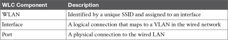
WLANs are identified by unique SSID network names. The LAN is a logical entity. Each WLAN is assigned to an interface in the WLC. Each WLAN is configured with radio policies, quality of service (QoS), and other WLAN parameters.
A WLC interface is a logical connection that maps to a VLAN on the wired network. Each interface is configured with a unique IP address, default gateways, physical ports, VLAN tag, and DHCP server.
Table 5-7 covers the WLC components.
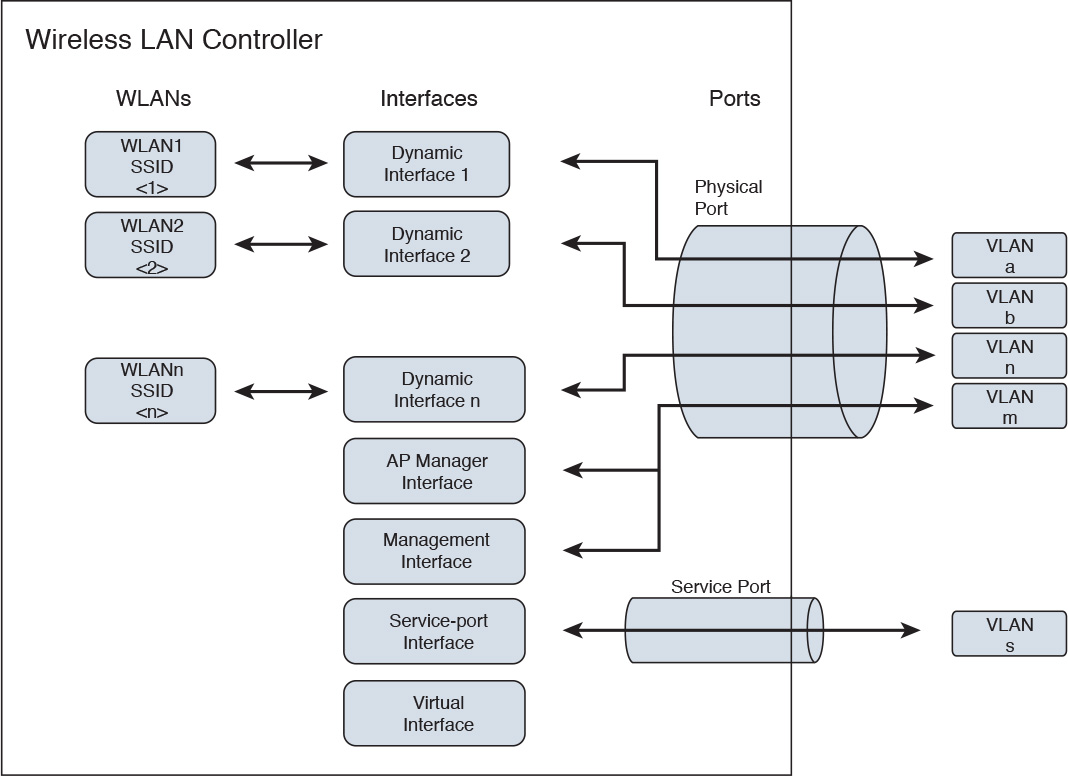
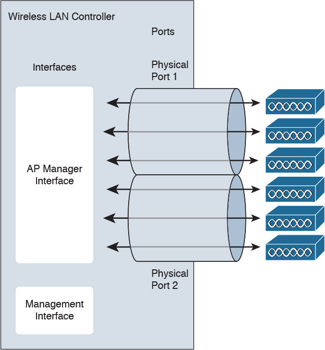
The port is a physical connection to the neighboring switch or router. By default, each port is an IEEE 802.1Q trunk port. There may be multiple ports on a WLC into a single port-channel interface. These ports can be aggregated using link aggregation (LAG). Some WLCs have a service port that is used for out-of-band management. Figure 5-8 shows the WLC components.
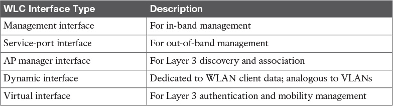
WLC Interface Types
A WLC has five interface types:
![]() Management interface (static, configured at setup, mandatory) is used for in-band management, connectivity to AAA, and Layer 2 discovery and association.
Management interface (static, configured at setup, mandatory) is used for in-band management, connectivity to AAA, and Layer 2 discovery and association.
![]() Service-port interface (static, configured at setup, optional) is used for out-of-band management. It is an optional interface that is statically configured.
Service-port interface (static, configured at setup, optional) is used for out-of-band management. It is an optional interface that is statically configured.
![]() AP manager interface (static, configured at setup, mandatory except for 5508 WLC) is used for Layer 3 discovery and association. It has the source IP address of the AP that is statically configured.
AP manager interface (static, configured at setup, mandatory except for 5508 WLC) is used for Layer 3 discovery and association. It has the source IP address of the AP that is statically configured.
![]() Dynamic interface (dynamic) is analogous to VLANs and is designated for WLAN client data.
Dynamic interface (dynamic) is analogous to VLANs and is designated for WLAN client data.
![]() Virtual interface (static, configured at setup, mandatory) is used for Layer 3 security authentication, DHCP relay support, and mobility management.
Virtual interface (static, configured at setup, mandatory) is used for Layer 3 security authentication, DHCP relay support, and mobility management.
Table 5-8 summarizes WLC interface types.
AP Controller Equipment Scaling
Cisco provides different solutions to support the differing numbers of APs present in enterprise customers. Standalone devices, modules for Integrated Services Routers (ISRs), and modules for 6500 switches support numerous APs. Table 5-9 lists the platforms and the number of APs supported.

To scale beyond the default number of APs on a Cisco WLC, use link aggregation (LAG). This option is supported by 5500 series controllers and is the default for 3850G Integrated WLC and Catalyst 6500 series WiSM.
Figure 5-9 shows the use of LAG. With LAG, the system dynamically manages port redundancy and load-balances APs across an EtherChannel interface transparently. The default limit of APs per port does not apply when LAG is enabled.
One limitation of LAG is that the WLC platforms only support one LAG group per controller. When LAG is enabled, all the physical ports, excluding the services port, are included in the bundle. Therefore, the WLC using LAG cannot be connected to more than one neighbor device.
Roaming and Mobility Groups
The primary reason to have wireless networks is roaming: the ability to access network resources from common areas and in areas where it is difficult to run cabling. End clients might want to move from one location to another. Mobility allows users to access the network from several locations. Roaming occurs when the wireless client changes association from one AP to another. The challenge is to scale the wireless network to allow client roaming that is seamless and secure. Roaming can be intracontroller or intercontroller.
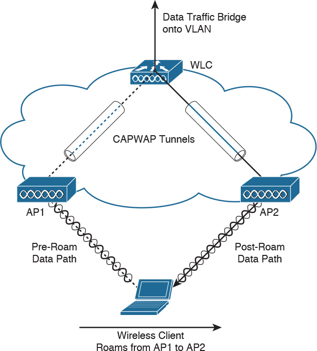
Intracontroller Roaming
Intracontroller roaming, shown in Figure 5-10, occurs when a client moves association from one AP to another AP that is joined to the same WLC. The WLC updates the client database with the new associated AP and does not change the client’s IP address. If required, clients are reauthenticated, and a new security association is established. The client database remains on the same WLC.
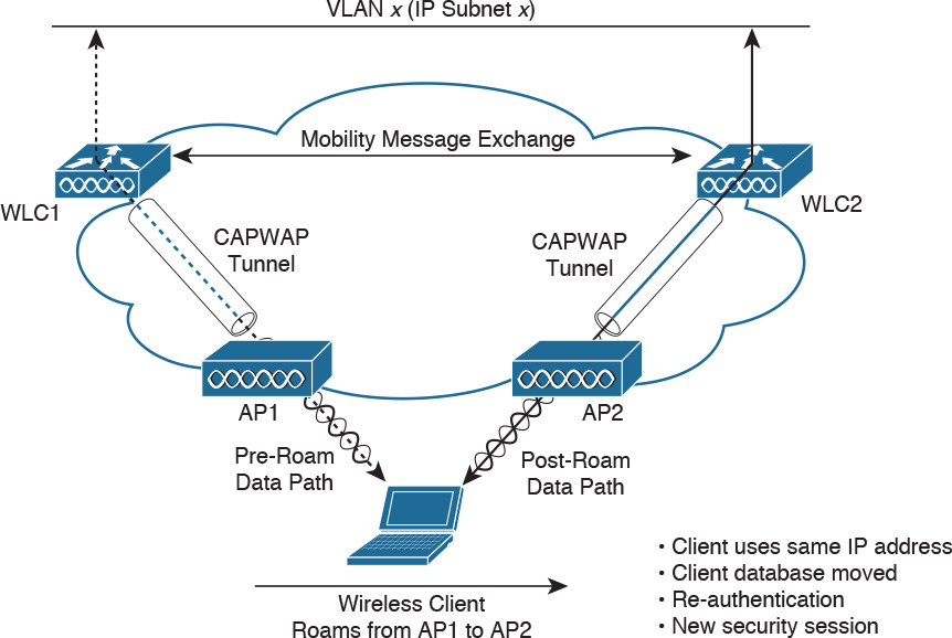
Layer 2 Intercontroller Roaming
Intercontroller roaming occurs when a client moves association from one AP to another AP that is joined to a different WLC that is on the same subnet. The Layer 2 roam occurs when the client traffic is bridged to the same IP subnet. Figure 5-11 shows Layer 2 intercontroller roaming. Traffic remains of the same IP subnet, and no IP address changes to the client occur. The client database is moved from WLC1 to WLC2. The client is reauthenticated transparently, and a new security session is established.
Layer 3 Intercontroller Roaming
With Layer 3 intercontroller roaming, shown in Figure 5-12, a client moves association from one AP to another AP that is joined to a different WLC that is on a different IP subnet than the first WLC. Then the traffic is bridged onto a different IP subnet. When the client associates to AP2, WLC2 then exchanges mobility messages with WLC1. The original client database is not moved to WLC2. Instead, WLC1 marks the client with an “Anchor” entry in its database. The database entry is copied to WLC2’s database and is marked as a “Foreign” entry. The wireless client maintains its original IP address and is reauthenticated. A new security session is then established.
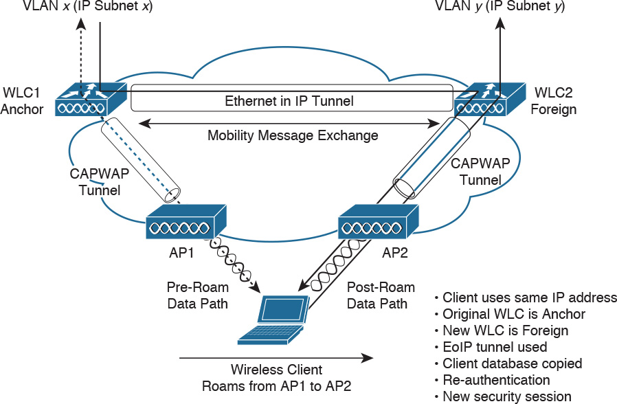
Client traffic then routes in an asymmetric manner. Traffic from the client is forwarded by the Foreign WLC, but traffic to the client arrives at the Anchor WLC, which forwards it through an Ethernet-in-IP (EtherIP) tunnel to the Foreign WLC. The Foreign WLC forwards the data traffic to the client.
Mobility Groups
Mobility groups allow controllers to peer with each other to support roaming across controller boundaries. This also allows for AP load balancing and controller redundancy.
When you assign WLCs to mobility groups, the WLCs dynamically exchange mobility messages and data is tunneled via EtherIP between the Anchor and Foreign AP. WLCs should be placed in mobility groups when intercontroller roaming is possible and for controller redundancy.
Mobility groups support up to 24 controllers. The upper limit of APs supported in a mobility group is determined by the number of APs that the controllers support, which varies by controller type. A mobility list is a group of controllers configured on a single controller that specifies members in different mobility groups. Controllers can communicate across mobility groups, and clients can roam between APs in different mobility groups if the controllers are included in each other’s mobility lists. Each WLC is configured with a list of the members in the mobility group. Mobility lists can support up to 72 controllers with Release 5.1 or later, or up to 48 controllers with Release 5.0.
The WLCs exchange messages using UDP port 16666 for unencrypted messages or UDP port 16667 for encrypted messages. APs learn the IP addresses of other members of the mobility group after the CAPWAP join process.
As an example of the scalability, if 24 Cisco 2504 WLCs (75 APs supported per 2504 WLC) are used, then 1800 APs (24 * 75 = 1800) are supported.
As a best practice, Cisco recommends minimizing intercontroller roaming in the network. It is also recommended that there be less than 10 ms of round-trip time latency between controllers. Cisco also states that Layer 2 roaming is more efficient than Layer 3 roaming because of the asymmetric communication of Layer 3 roaming. Proactive key caching (PKC) or Cisco Compatible Extensions (CCKM) Version 4 is recommended to speed up and secure roaming.
WLAN Design
This section covers controller redundancy design, radio frequency groups, site survey, and WLAN design considerations.
Controller Redundancy Design: Deterministic vs. Dynamic
WLCs can be configured for dynamic or deterministic redundancy. For deterministic redundancy, the AP is configured with a primary, secondary, and tertiary controller. This requires more upfront planning but allows better predictability and faster failover times. Deterministic redundancy is the recommended best practice. N+1, N+N, and N+N+1 are examples of deterministic redundancy. Advantages of deterministic redundancy include
![]() Predictability
Predictability
![]() Network stability
Network stability
![]() Flexible and powerful redundancy design options
Flexible and powerful redundancy design options
![]() Faster failover times
Faster failover times
![]() A fallback option in case of failover
A fallback option in case of failover
The disadvantage of deterministic controller redundancy is that it requires more upfront planning and configuration.
Dynamic controller redundancy uses CAPWAP to load-balance APs across WLCs. CAPWAP populates APs with a backup WLC. This solution works better when WLCs are in a centralized cluster. The disadvantages are longer failover times and unpredictable operation. An example is adjacent APs registering with differing WLCs.
Advantages of dynamic controller redundancy include
![]() Easy to deploy and configure
Easy to deploy and configure
![]() Access points dynamically load-balance
Access points dynamically load-balance
Disadvantages include longer failover times, unpredictable operation, more intercontroller roaming, and no fallback option in the event of controller failure.
N+1 WLC Redundancy
With N+1 redundancy, shown in Figure 5-13, a single WLC acts as the backup of multiple WLCs. The backup WLC is configured as the secondary WLC on each AP. One design constraint is that the backup WLC might become oversubscribed if there are too many failures of the primary controllers. The secondary WLC is the backup controller for all APs and it is normally placed in the data center.

N+N WLC Redundancy
With N+N redundancy, shown in Figure 5-14, an equal number of controllers back up each other. For example, a pair of WLCs on one floor serves as a backup to a second pair on another floor. The top WLC is primary for AP1 and AP2 and secondary for AP3 and AP4. The bottom WLC is primary for AP3 and AP4 and secondary for AP1 and AP2. The provisioned controllers should be sized with enough capacity to manage a failover situation.

N+N+1 WLC Redundancy
With N+N+1 redundancy, shown in Figure 5-15, an equal number of controllers back up each other (as with N+N), plus a backup WLC is configured as the tertiary WLC for the APs. N+N+1 redundancy functions the same as N+N redundancy, plus there’s a tertiary controller that backs up the secondary controllers. The tertiary WLC is placed in the data center or network operations center.
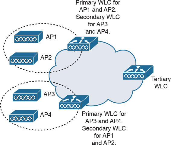
Table 5-10 summarizes WLC redundancy.

Radio Management and Radio Groups
The limit of available channels in the ISM frequencies used by the IEEE 802.11b/g/n standard presents challenges to the network designer. There are three nonoverlapping channels (channels 1, 6, and 11). The recommended best practice is to limit the number of data devices connected to each AP to 30, or no more than seven concurrent voice over WLAN (VoWLAN) calls using G.711 or eight concurrent VoWLAN calls using G.729. Additional APs should be added as user population grows to maintain this ratio of data and voice per AP.
Cisco Radio Resource Management (RRM) is a method to manage AP RF channel and power configuration. Cisco WLCs use the RRM algorithm to automatically configure, optimize, and self-heal. Cisco RRM functions are as follows:
![]() Radio resource monitoring: Cisco LAPs monitor all channels. Collected packets are sent to the WLC, which can detect rogue APs, clients, and interfering APs.
Radio resource monitoring: Cisco LAPs monitor all channels. Collected packets are sent to the WLC, which can detect rogue APs, clients, and interfering APs.
![]() Dynamic channel assignment: WLCs automatically assign channels to avoid interference.
Dynamic channel assignment: WLCs automatically assign channels to avoid interference.
![]() Interference detection and avoidance: As Cisco LAPs monitor all channels, interference is detected by a predefined threshold (10 percent by default). Interference can be generated by rogue APs, microwaves, cordless telephones, Bluetooth devices, neighboring WLANs, or other electronic devices.
Interference detection and avoidance: As Cisco LAPs monitor all channels, interference is detected by a predefined threshold (10 percent by default). Interference can be generated by rogue APs, microwaves, cordless telephones, Bluetooth devices, neighboring WLANs, or other electronic devices.
![]() Dynamic transmit power control: The WLCs automatically adjust power levels.
Dynamic transmit power control: The WLCs automatically adjust power levels.
![]() Coverage hole detection and correction: WLCs may adjust the power output of APs if clients report that a low received signal strength indication (RSSI) level is detected.
Coverage hole detection and correction: WLCs may adjust the power output of APs if clients report that a low received signal strength indication (RSSI) level is detected.
![]() Client and network load balancing: Clients can be influenced to associate with certain APs to maintain network balance.
Client and network load balancing: Clients can be influenced to associate with certain APs to maintain network balance.
With AP self-healing, WLCs use RRM to raise the power levels and adjust the channel selection of neighbor APs to compensate for loss of coverage of a failed AP. APs report a lost neighbor when they no longer receive neighbor messages at –70 dBm.
RF Groups
An RF group is a cluster of WLC devices that coordinate their RRM calculations. When the WLCs are placed in an RF group, the RRM calculation can scale from a single WLC to multiple floors, buildings, or even the campus. As shown in Figure 5-16, APs send neighbor messages to other APs. If the neighbor message is above –80 dBm, the controllers form an RF group. The WLCs elect an RF group leader to analyze the RF data. The RF group leader exchanges messages with the RF group members using UDP port 12114 for 802.11b/g/n and UDP port 12115 for 802.11a.

RF groups are formed with the following process:
1. APs send out neighbor messages over the air. The message includes an encrypted shared secret that is configured in the WLC and pushed to each AP.
2. APs sharing the same secret are able to validate messages from each other. Neighbor messages need to be over –80 dBm to form an RF group.
3. The members in the RF group elect an RF group leader to maintain a “master” power and channel scheme for the RF group. The RF group leader analyzes real-time radio data collected by the system and calculates the master power and channel plan.
RF Site Survey
Similar to performing an assessment for a wired network design, RF site surveys are done to determine design parameters for WLANs and customer requirements. RF site surveys help determine the coverage areas and check for RF interference. This helps determine the appropriate placement of wireless APs.
The RF site survey has the following steps:
Step 1. Define customer requirements, such as service levels and support for VoIP. Determine devices to support as well as sites where wireless devices will be located.
Step 2. Obtain a facility diagram to identify the potential RF obstacles.
Step 3. Visually inspect the facility to look for potential barriers to the propagation of RF signals, such as metal racks, elevator shafts, and stairwells.
Step 4. Identify user areas that may be intensively used, such as conference rooms, and areas that are not heavily used, such as stairwells.
Step 5. Determine preliminary AP locations, which need power, wired network access, cell coverage and overlap, channel selection, mounting locations, and antennas.
Step 6. Perform the actual survey by using an AP to survey the location and received RF strength based on the targeted AP placement. Consider the effects of electrical machinery. Microwave ovens and elevators might distort the radio signal from the APs.
Step 7. Document the findings by recording the target AP locations, log signal readings, and data rates at outer boundaries. Information included in the report includes the following:
![]() Detail customer requirements; describe and diagram AP coverage.
Detail customer requirements; describe and diagram AP coverage.
![]() Parts list, including APs, antennas, accessories, and network components.
Parts list, including APs, antennas, accessories, and network components.
![]() Describe tools used and methods used for the survey.
Describe tools used and methods used for the survey.
Using EoIP Tunnels for Guest Services
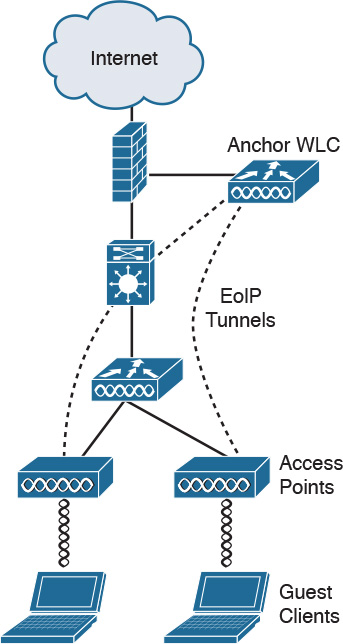
Basic solutions use separate VLANs for guest and corporate users to segregate guest traffic from corporate traffic. The guest SSID is broadcast, but the corporate SSID is not. All other security parameters are configured. Another solution is to use Ethernet over IP (EoIP) to tunnel the guest traffic from the CAPWAP to an anchor WLC.
As shown in Figure 5-17, EoIP is used to logically segment and transport guest traffic from the edge AP to the Anchor WLC. There is no need to define guest VLANs in the internal network, and corporate traffic is still locally bridged. The Ethernet frames from the guest clients are maintained across the CAPWAP and EoIP tunnels.
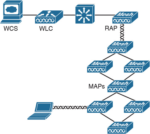
Wireless Mesh for Outdoor Wireless
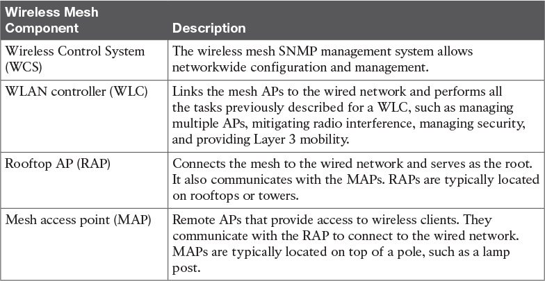
Traditionally, outdoor wireless solutions have been limited to point-to-point and point-to-multipoint bridging between buildings. With these solutions, each AP is wired to the network. The Cisco wireless mesh networking solution, shown in Figure 5-18, eliminates the need to wire each AP and allows users to roam from one area to another without having to reconnect.
The wireless mesh components are shown in Table 5-11.
Mesh Design Recommendations
The following are Cisco recommendations (and considerations) for mesh design:
![]() There is a < 10ms latency per hop. Typically 2 ms to 3 ms.
There is a < 10ms latency per hop. Typically 2 ms to 3 ms.
![]() For outdoor deployment, four or fewer hops are recommended for best performance. A maximum of eight hops is supported.
For outdoor deployment, four or fewer hops are recommended for best performance. A maximum of eight hops is supported.
![]() For indoor deployment, one hop is supported.
For indoor deployment, one hop is supported.
![]() For best performance, 20 MAP nodes per RAP is recommended. Up to 32 MAPs is supported per RAP.
For best performance, 20 MAP nodes per RAP is recommended. Up to 32 MAPs is supported per RAP.
![]() Throughput: one hop =14 Mbps, two hops = 7 Mbps, three hops = 3 Mbps, four hops = 1 Mbps.
Throughput: one hop =14 Mbps, two hops = 7 Mbps, three hops = 3 Mbps, four hops = 1 Mbps.
Campus Design Considerations
When designing for the Cisco Unified Wireless Network, you need to be able to determine how many LAPs to place and how they will be managed with the WLCs. Table 5-12 summarizes campus design considerations.

Power over Ethernet (PoE)
The use of PoE is an important aspect to the design of a campus network. PoE plays a role in powering IP phones and wireless APs. There are two PoE standards:
![]() IEEE 802.3af: Standard that provides 15.4 watts per port.
IEEE 802.3af: Standard that provides 15.4 watts per port.
![]() IEEE 802.3at: Newer standard for higher power requirements. Provides 30 watts.
IEEE 802.3at: Newer standard for higher power requirements. Provides 30 watts.
Newer wireless standards, such as 802.11ac, provide high bandwidth but with the requirement of higher power requirements. The 802.3at standard provides 30 watts of power using two pairs of Category 5e (or better) UTP cable.
Ensure that the switch can provide enough power for all its ports. For example, if a 48-port switch needs to provide 15.4 watts for each port, it will need to provide a total 740 watts of power.
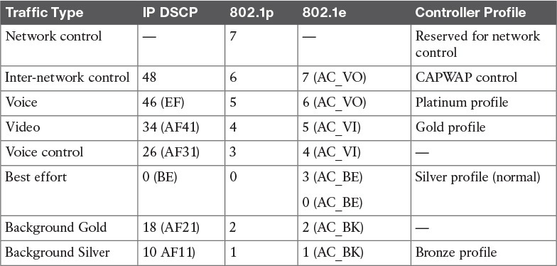
Wireless and Quality of Service (QoS)
Wireless networks operate differently from wired networks because they are multiple access broadcast networks. Whereas IEEE 802.1p is used for Layer 2 QoS in wired networks, IEEE 802.11e defines mechanisms for implementing Layer 2 QoS in wireless LANs. A translation between IP DSCP, 802.11e, and 802.1p values needs to occur. Table 5-13 describes Cisco’s recommendations where four Wi-Fi Multimedia (WMM) categories are used:
![]() AC_VO: Access category for voice
AC_VO: Access category for voice
![]() AC_VI: Access category for video
AC_VI: Access category for video
![]() AC_BE: Access category for best effort
AC_BE: Access category for best effort
![]() AC_BK: Access category for background traffic
AC_BK: Access category for background traffic
For traffic traveling from the client to the WLC and the wired network, CoS/QoS works as follows:
1. The 802.11e CoS marking on the frame arriving at the AP is translated to a DSCP value on the outside of the CAPWAP tunnel.
2. The CAPWAP packet is decapsulated at the WLC, and the original DSCP value of the IP packet is used for translation to the wired CoS value.
3. The DSCP marking on the packet leaving the WLC on its way to the wired network will, by default, have the DSCP setting equal to the packet that left the WLAN client.
For traffic from the wired network to the wireless client, CoS/QoS works as follows:
1. The 802.1p markings are read at the WLC’s wired interface.
2. The WLC reads the DSCP value and copies it to the DSCP value of the CAPWAP header.
3. The AP translates the DSCP value of the CAPWAP packet into the 802.11e value of the outgoing wireless Ethernet frame.
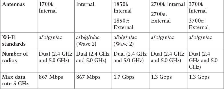
Table 5-14 compares the indoor AP features for Cisco APs.

Branch Design Considerations
For branch networks, you need to consider the number and placement of APs, which depends on the location and expected number of wireless clients at the branch office. It may not be cost-justifiable to place a WLC at each branch office of an enterprise. One requirement is that the round-trip time (RTT) between the AP and the WLC should not exceed 300 ms. For centralized controllers, it is recommended that you use REAP or Hybrid REAP (H-REAP).
Local MAC
CAPWAP supports local media access control (local MAC), which can be used in branch deployments. Unlike with split-MAC, the AP provides MAC management support for association requests and actions. Local MAC terminates client traffic at the wired port of the AP versus at the WLC. This allows direct local access to branch resources without requiring the data to travel to the WLC at the main office. Local MAC also allows the wireless client to function even if a WAN link failure occurs.
REAP
REAP is designed to support remote offices by extending LWAPP control timers. With REAP control, traffic is still encapsulated over an LWAPP tunnel and is sent to the WLC. Management control and RF management are done over the WAN. Client data is locally bridged. With REAP, local clients still have local connectivity if the WAN fails.
WLCs support the same number of REAP devices as APs. REAP devices support only Layer 2 security policies, do not support Network Address Translation (NAT), and require a routable IP address.
Hybrid REAP
H-REAP is an enhancement to REAP that provides additional capabilities such as NAT, more security options, and the ability to control up to three APs remotely. It is the preferred solution for remote or small office APs to connect to the wireless controllers over the WAN.
H-REAP operates in two security modes:
![]() Standalone mode: H-REAP does the client authentication itself when the WLC cannot be reached. In standalone mode, H-REAP supports WPA-PSK and WPA2-PSK for client authentication.
Standalone mode: H-REAP does the client authentication itself when the WLC cannot be reached. In standalone mode, H-REAP supports WPA-PSK and WPA2-PSK for client authentication.
![]() Connected mode: The device uses the WLC for client authentication. In connected mode, H-REAP supports WPA-PSK, WPA2-PSK, VPNs, L2TP, EAP, and web authentication for client authentication.
Connected mode: The device uses the WLC for client authentication. In connected mode, H-REAP supports WPA-PSK, WPA2-PSK, VPNs, L2TP, EAP, and web authentication for client authentication.
H-REAP is delay sensitive. The RTT must not exceed 300 ms between the AP and the WLC. And, CAPWAP must be prioritized over other traffic.
Branch Office Controller Options
For branch offices, Cisco recommends one of four options:
![]() CTVM virtual controller: Supports up to 200 LAPs.
CTVM virtual controller: Supports up to 200 LAPs.
![]() WLC module in Integrated Services Router (ISR): The ISR-G2-UCS-E supports up to 200 LAPs.
WLC module in Integrated Services Router (ISR): The ISR-G2-UCS-E supports up to 200 LAPs.
![]() 3650 WLAN controller: Supports 50 LAPs.
3650 WLAN controller: Supports 50 LAPs.
![]() Cisco 2500 series controllers: Supports up to 75 LAPs
Cisco 2500 series controllers: Supports up to 75 LAPs
The following points summarize WLAN design:
![]() An RF site survey is used to determine a wireless network’s RF characteristics and AP placement.
An RF site survey is used to determine a wireless network’s RF characteristics and AP placement.
![]() Guest services are easily supported using EoIP tunnels in the Cisco Unified Wireless Network.
Guest services are easily supported using EoIP tunnels in the Cisco Unified Wireless Network.
![]() Outdoor wireless networks are supported using outdoor APs and Cisco wireless mesh networking APs.
Outdoor wireless networks are supported using outdoor APs and Cisco wireless mesh networking APs.
![]() Campus wireless network design provides RF coverage for wireless clients in the campus using LAPs. The LAPs are managed by WLCs.
Campus wireless network design provides RF coverage for wireless clients in the campus using LAPs. The LAPs are managed by WLCs.
![]() Branch wireless network design provides RF coverage for wireless clients in the branch. Central management of REAP or H-REAP APs can be supported.
Branch wireless network design provides RF coverage for wireless clients in the branch. Central management of REAP or H-REAP APs can be supported.
![]() Each AP should be limited to 30 data devices per WLAN SSID.
Each AP should be limited to 30 data devices per WLAN SSID.
![]() For voice over wireless design, it is recommended that a separate SSID be used for voice and that each AP support roughly seven (G.711) to eight (G.729) voice calls over VoWLAN. This is because all devices share bandwidth.
For voice over wireless design, it is recommended that a separate SSID be used for voice and that each AP support roughly seven (G.711) to eight (G.729) voice calls over VoWLAN. This is because all devices share bandwidth.
Table 5-15 provides a quick summary of the UDP ports used by wireless protocols.

References and Recommended Readings
Cisco Outdoor Wireless Network Solution, http://www.cisco.com/c/en/us/products/wireless/outdoor-wireless/index.html.
Cisco Unified Wireless Network, http://www.cisco.com/c/en/us/products/wireless/index.html.
Cisco Wireless Control System, http://www.cisco.com/c/en/us/products/wireless/wireless-control-system/index.html.
Cisco Compare Wireless LAN Controllers, http://www.cisco.com/c/en/us/products/wireless/buyers-guide.html#~controllers.
802.11ac: The Fifth Generation of Wi-Fi Technical White Paper, http://www.cisco.com/c/en/us/products/collateral/wireless/aironet-3600-series/white_paper_c11-713103.html?cachemode=refresh.
QoS on Wireless LAN Controllers and Lightweight APs Configuration Example, http://www.cisco.com/c/en/us/support/docs/wireless-mobility/wireless-lan-wlan/81831-qos-wlc-lap.html.
Cisco 802.11ac Wave 2 FAQ, http://www.cisco.com/c/en/us/solutions/collateral/enterprise-networks/802-11ac-solution/q-and-a-c67-734152.html.
802.11 WLAN Roaming and Fast-Secure Roaming on CUWN, http://www.cisco.com/c/en/us/support/docs/wireless-mobility/wireless-lan-wlan/116493-technote-technology-00.html#anc8.
Enterprise Mobility 8.1 Design Guide, http://www.cisco.com/c/en/us/td/docs/wireless/controller/8-1/Enterprise-Mobility-8-1-Design-Guide/Enterprise_Mobility_8-1_Deployment_Guide.html.
IEEE Std 802.11g-2003. Amendment to IEEE Std 802.11, 1999 Edition.
Lightweight Access Point FAQ, http://www.cisco.com/c/en/us/support/docs/wireless/aironet-1200-series/70278-lap-faq.html.
Light Weight Access Point Protocol (LWAPP), draft-ohara-capwap-lwapp-02, http://tools.ietf.org/html/draft-ohara-capwap-lwapp-02.
RFC 5415: Control and Provisioning of Wireless Access Points (CAPWAP) Protocol Specification, http://tools.ietf.org/search/rfc5415.
RFC 5416: Control and Provisioning of Wireless Access Points (CAPWAP) Protocol Binding for IEEE 802.11, http://tools.ietf.org/search/rfc54156.
Cisco Wireless LAN Controller FAQ, http://www.cisco.com/c/en/us/support/docs/wireless/4400-series-wireless-lan-controllers/69561-wlc-faq.html.
Cisco Wireless LAN Controller Best Practices, http://www.cisco.com/c/en/us/support/docs/wireless-mobility/wireless-lan-wlan/82463-wlc-config-best-practice.html.
“Wireless LAN MAC and Physical Layer (PHY) Specifications,” IEEE 802.11-1999. Piscataway, New Jersey: Institute of Electrical and Electronics Engineers, 1999.
Exam Preparation Tasks
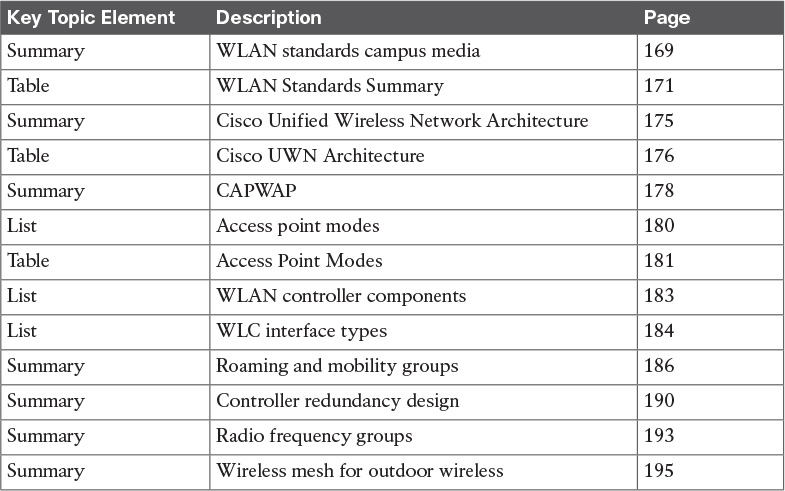
Review All Key Topics
Review the most important topics in the chapter, noted with the Key Topic icon in the outer margin of the page. Table 5-16 lists a reference of these key topics and the page numbers on which each is found.
Complete Tables and Lists from Memory
Print a copy of Appendix D, “Memory Tables” (found on the book website), or at least the section for this chapter, and complete the tables and lists from memory. Appendix E, “Memory Tables Answer Key,” also on the website, includes completed tables and lists to check your work.
Define Key Terms
Define the following key terms from this chapter, and check your answers in the glossary:
Q&A
The answers to these questions appear in Appendix A. For more practice with exam format questions, use the exam engine on the book website.
1. What is the maximum data rate of IEEE 802.11ac Wave 1?
2. What is the typical data rate of IEEE 802.11n?
3. What are some difficulties with having to manage hundreds of standalone APs?
4. What standard does IEEE 802.11i use for confidentiality, integrity, and authentication?
5. List at least four benefits of Cisco UWN.
6. True or false: With split-MAC, the control and data frames are load-balanced between the LAP and the WLC.
7. True or false: With split-MAC, the WLC, not the LAP, is responsible for authentication and key management.
8. What CAPWAP transport mode is the preferred and most scalable?
a. Intra
b. Layer 2
c. Layer 3
d. EoIP
9. What is the preferred intercontroller roaming option?
a. Intra
b. Layer 2
c. Layer 3
d. EoIP
10. What device places user traffic on the appropriate VLAN?
a. LAP
b. WLAN controller
c. MAP
d. RAP
11. How many access points are supported in a mobility group using Cisco series 2500 WLCs?
a. 144
b. 1200
c. 1800
d. 7200
12. What is the recommended number of data devices an AP can support for best performance?
a. About 6
b. 7 to 8
c. 10 to 15
d. About 20
13. What is the recommended number of VoWLAN devices an AP can support for best performance?
a. 2 to 3
b. 7 to 8
c. 10 to 15
d. About 20
14. What method is used to manage radio frequency channels and power configuration?
a. WLC
b. WCS
c. RRM
d. MAP
15. What is the typical latency per wireless mesh hop in milliseconds?
a. 1 to 3
b. 7 to 8
c. 10 to 15
d. About 20
16. What is the recommended maximum RTT between an AP and the WLC?
a. 20 ms
b. 50 ms
c. 100 ms
d. 300 ms
17. What is the recommended controller redundancy technique?
a. N+1+N
b. Static
c. Dynamic
d. Deterministic
18. What is the recommended best practice for guest services?
a. Use separate VLANs.
b. Use separate routers and access lists.
c. Obtain a DSL connection and bridge to the local LAN.
d. Use EoIP to isolate traffic to the DMZ.
19. What is the recommended best practice for branch WLANs?
a. Use H-REAP with centralized controllers.
b. Use local-MAP.
c. Use wireless mesh design.
d. Use EoIP.
20. What are two recommended best practices for WLC design?
a. Maximize intercontroller roaming.
b. Minimize intercontroller roaming.
c. Use distributed controller placement.
d. Use centralized controller placement.
21. How many APs does the WiSM2 WLC module support?
a. 6
b. 50
c. 100
d. 1000
22. Match each access point mode with its description:
i. Local
ii. REAP
iii. Monitor
iv. Rogue detector
v. Sniffer
vi. Bridge
a. For location-based services
b. Captures packets
c. For point-to-point connections
d. Default mode
e. Management across the WAN
f. Monitors rogue APs
23. Match each WLC interface type with its description.
i. Management
ii. Service port
iii. AP manager
iv. Dynamic
v. Virtual
a. Authentication and mobility
b. Analogous to user VLANs
d. Out-of-band management
e. In-band management
24. Match each roaming technique with its client database entry change.
i. Intracluster roaming
ii. Layer 2 intercluster roaming
iii. Layer 3 intercluster roaming
a. The client entry is moved to a new WLC.
b. The client entry is updated on the same WLC.
c. The client entry is copied to a new WLC.
25. Match each UDP port with its protocol.
i. LWAPP data
ii. RF group 802.11b/g
iii. WLC encrypted exchange
iv. LWAPP control
v. WLC unencrypted exchange
vi. CAPWAP control
vii. CAPWAP data
a. UDP 12114
b. UDP 12222
c. UDP 5246
d. UDP 5247
e. UDP 12223
f. UDP 16666
g. UDP 16667
26. Match each wireless mesh component with its description.
i. WCS
ii. WLC
iii. RAP
iv. MAP
a. Root of the mesh network
b. Remote APs
c. Networkwide configuration and management
d. Links APs to the wired network
27. How many MAP nodes are recommended per rooftop AP?
a. 6
b. 20
c. 500
d. 100
28. Which of the following shows the correct order of the steps in an RF site survey?
a. Define requirements, document findings, perform the survey, determine preliminary AP locations, identify coverage areas.
b. Define requirements, perform the survey, determine preliminary AP locations, identify coverage areas, document findings.
c. Identify coverage areas, define requirements, determine preliminary AP locations, perform the survey, document findings.
d. Define requirements, identify coverage areas, determine preliminary AP locations, perform the survey, document findings.
29. What technique performs dynamic channel assignment, power control, and interference detection and avoidance?
a. CAPWAP
b. RRM
c. Mobility
d. LEAP
30. What are the three nonoverlapping channels of IEEE 802.11b/g/n?
a. Channels A, D, and G
b. Channels 1, 6, and 11
c. Channels 3, 8, and 11
d. Channels A, E, and G
31. Which of the following statements is true?
a. IEEE 802.11g is backward compatible with 802.11b; 802.11a is not compatible with 802.11b.
b. IEEE 802.11a is backward compatible with 802.11b; 802.11g is not compatible with 802.11b.
c. IEEE 802.11b is backward compatible with 802.11a; 802.11g is not compatible with 802.11b.
d. IEEE 802.11n is backward compatible with 802.11a and 802.11g.
32. What is necessary when you use LEAP for authentication?
a. WLC
b. WCS
c. RADIUS server
d. LAP
33. A LAP is added to a network. What sequence accurately reflects the process it will use to associate with the WLAN controller?
a. First master, secondary, tertiary, greatest AP capacity
b. Primary, secondary, tertiary, greatest AP capacity, master
c. Primary, secondary, tertiary, master, greatest AP capacity
d. Greatest AP capacity, primary, secondary, master
34. A LAP is added to a network that is in a separate IP subnet from the WLAN controller. OTAP has not been enabled. Which two methods can be used by the LAP to find the WLAN controller?
a. DHCP
b. Primary, secondary, tertiary, greatest AP capacity, master
c. Primary, secondary, tertiary, master, greatest AP capacity
d. Greatest AP capacity, primary, secondary, master
e. DNS
f. Local subnet broadcast
35. Which statement is true regarding wireless QoS?
a. When the WLC receives a packet from the wired network, it copies the 802.1e value to the DSCP value of the CAPWAP header.
b. When the WLC receives a packet from the wired network, it copies the DSCP value to the DSCP value of the CAPWAP header.
c. When the WLC receives a packet from the wired network, it copies the 802.1e value to the 802.1p value of the CAPWAP header.
d. When the WLC receives a packet from the wireless network, it copies the 802.1e value to the DSCP value of the CAPWAP header.
36. Which two of the following statements represent a preferred split-MAC LWAPP implementation? (Select two.)
a. IEEE 802.1Q trunking extends from the wired infrastructure to a WLAN controller. Then the 802.1Q packet is encapsulated in CAPWAP or LWAPP and sent to the access point for transmission over the SSID.
b. Each wireless client authentication type maps to a unique SSID, which in turn maps to a common shared VLAN.
c. 802.1Q trunking extends from the wired infrastructure to the access point for translation into SSIDs.
d. Each wireless client authentication type maps to a unique SSID, which in turn maps to a unique VLAN.
e. 802.1Q trunking extends from the wired infrastructure to a WLAN controller for translation into SSIDs.
37. Which two of the following are required for Cisco wireless client mobility deployment?
a. Matching security
b. Matching mobility group name
c. Matching RF channel
d. Matching RF group name
e. Matching RF power
f. Assigned master controller
38. Which of the following describe best practices for Cisco outdoor wireless mesh networks? (Select three.)
a. RAP implemented with 20 or fewer MAP nodes
b. RAP implemented with 20 to 32 MAP nodes
c. Mesh hop counts of four or fewer
d. Mesh hop counts of eight to four
e. Client access via 802.11b/g and backhaul with 802.11a
f. Client access via 802.11a and backhaul with 802.11b/g
39. Which of the following describe best practices for Cisco WLAN guest access? (Select two.)
a. Guest tunnels have limitations on which wireless controllers can originate the tunnel.
b. Guest tunnels have limitations on which wireless controllers can terminate the tunnel.
c. Dedicated guest VLANs are only extended to the wireless controllers in the network to ensure path isolation.
d. Dedicated guest VLANs are extended throughout the network to the access points for path isolation.
e. Dedicated guest access in the DMZ extends from the origination to the termination controllers without dedicated guest VLANs.
f. Guest tunnels can originate and terminate on any wireless controller platform.
40. How are WLANs identified?
a. MAC addresses
b. IP subnet
c. SSID
d. WEP key
e. LAN ports
f. Secure encryption key
41. Which description is correct regarding wireless solutions that provide higher bandwidth than point-to-multipoint (p2mp) wireless?
a. P2p links tend to be slower than p2mp.
b. P2mp wireless connections can provide up to 1.544 Mbps of raw bandwidth.
c. P2p wireless connections can provide up to 44 Mbps of raw bandwidth.
d. P2mp links tend to be faster than p2mp.
42. Which WLAN attributes should be considered during a site survey? (Select two.)
a. Channels
b. Power
c. SSID
d. Network name
e. Authentication
f. Encryption
43. Which WLC interfaces are mandatory? (Select all that apply.)
a. Management
b. AP manager
c. Dynamic
d. Virtual
e. Service port
f. Extended
44. Which are differences between CAPWAP and LWAPP? (Select three.)
a. CAPWAP uses the newer AES. LWAPP uses DTLS.
b. CAPWAP uses DTLS. LWAPP uses AES.
c. CAPWAP control uses UDP 5246. LWAPP control uses UDP 12223.
d. CAPWAP control uses UDP 12223. LWAPP control uses UDP 5246.
e. CAPWAP is preferred.
f. LWAPP is preferred.
45. Which two of the following are functions of an access point in a split MAC architecture? (Choose two.)
a. 802.1Q encapsulation
b. EAP authentication
c. MAC layer encryption/decryption
d. Process probe response
46. Which WLC redundancy design allows for grouping of APs to minimize intercontroller roaming events?
a. N
b. N+1
c. N+N
d. N+N+1
47. Which AP mode excludes the AP from handling data traffic between clients and the infrastructure, allowing it to perform LBS functions?
a. Local mode
b. Monitor mode
c. Rogue Detector mode
d. Sniffer mode
48. Which AP mode allows the AP to receive a list MAC addresses from the LAN switch and then forwards that list and a list of MAC addresses listened over the air to the WLC?
a. Local mode
b. Monitor mode
c. Rogue Detector mode
d. Sniffer mode
49. Which AP mode is the default mode of operation?
a. Local mode
b. Monitor mode
c. Rogue Detector mode
d. Sniffer mode
50. A switch needs to provide 802.3af power to each of its 48 ports. How much power needs to be supplied?
a. 100 watts
b. 320 watts
c. 740 watts