Chapter 6. WAN Technologies and the Enterprise Edge
This chapter covers the following subjects:
WAN and Enterprise Edge Overview
WAN and Edge Design Methodologies
This chapter reviews wide area network technologies. Expect plenty of questions about the selection and use of WAN technologies and the enterprise edge. The CCDA must understand the various WAN technology options and what makes them different from each other. This chapter also covers WAN design methodologies and how quality of service (QoS) techniques can make better use of the available bandwidth. Finally, this chapter looks at the DMZ, Internet, and VPN network design in the enterprise edge.
“Do I Know This Already?” Quiz
The “Do I Know This Already?” quiz helps you identify your strengths and deficiencies in this chapter’s topics.
The ten-question quiz, derived from the major sections in the “Foundation Topics” portion of the chapter, helps you determine how to spend your limited study time.
Table 6-1 outlines the major topics discussed in this chapter and the “Do I Know This Already?” quiz questions that correspond to those topics.
1. What are two modules or blocks used in the enterprise edge?
a. Internet and campus core
b. Core and building access
c. Internet and DMZ
d. WAN and building distribution
2. What MAN/WAN technology has bandwidth available from 100 Mbps to 10 Gbps?
a. DSL
b. Metro Ethernet
c. TDM
d. Frame Relay
3. How much bandwidth does a T1 circuit provide?
a. 155 Mbps
b. 64 kbps
c. 15 Mbps
d. 1.544 Mbps
4. What methodology is used when designing the enterprise edge?
a. Cisco-powered network
b. ISL
c. PBM
d. IEEE
5. What technology delivers IP services using labels to forward packets from the source to the destination?
a. ADSL
b. Cable
c. Frame Relay
d. MPLS
6. Which of the following adds strict PQ to modular class-based QoS?
a. LLQ
b. FIFO
c. CBWFQ
d. WFQ
7. Which of the following VPNs provides an alternative to MPLS WAN services?
a. GRE VPN
b. Extranet VPN
c. Remote access VPN
8. What Internet connectivity option provides the highest level of resiliency for services?
a. Single-router dual-homed
b. Single-router single-homed
c. Shared DMZ
d. Dual-router dual-homed
9. What VPN application gives mobile users connectivity to corporate services over the Internet?
a. Remote access VPN
b. Site-to-site VPN
c. MPLS VPN
d. Extranet VPN
10. What VPNs are better suited for routing protocols such as OSPF and EIGRP?
a. Site-to-site VPN with IPsec over GRE
b. Remote access VPN
c. Site-to-site VPN
d. IPsec VPN
Foundation Topics
This chapter describes the WAN topics you need to master for the CCDA exam. These topics include the WAN modules included in the enterprise edge, WAN technologies, WAN technology selection considerations, and WAN design methodologies. In addition, this chapter describes quality of service (QoS) and how it can be used to prioritize network traffic and better utilize the available WAN bandwidth.
WAN and Enterprise Edge Overview
WANs provide network connectivity for the enterprise core and the remote branch locations. The enterprise edge, on the other hand, securely connects the enterprise core to the Internet in order to provide DMZ-type services such as VPN connectivity and other cloud-related services. Many WAN and Internet transport options are available, and new ones are continually emerging. When you are selecting WAN transport technologies, it is important to consider factors such as cost, bandwidth, reliability, and manageability, in addition to the hardware and software capabilities of the equipment. Moreover, enterprise branch offices can take advantage of a shared network such as MPLS WAN or use the Internet as a transport for secure VPN connectivity back to the headquarters or main office, which many are using today as a backup to their high-cost WAN circuits.
WAN Defined
Wide area networks (WAN) are communications networks used to connect geographically disperse network locations. Generally, WAN services are offered by service providers or telecommunication carriers. WANs can transport data, voice, and video traffic. Service providers charge fees, called tariffs, for providing WAN services or communications to their customers. Sometimes the term service is referred to as the WAN communications provided by the carrier.

When designing a WAN, you should become familiar with the design’s requirements, which typically derive from these two important goals:
![]() Service level agreement (SLA): Defines the availability of the network. Networked applications rely on the underlying network between the client and server to provide its functions. There are multiple levels of application availability that can be part of a negotiated SLA with a service provider. Organizations have to work with the carrier to define what level of service, such as bandwidth, allowed latency, and loss, is acceptable to the organization.
Service level agreement (SLA): Defines the availability of the network. Networked applications rely on the underlying network between the client and server to provide its functions. There are multiple levels of application availability that can be part of a negotiated SLA with a service provider. Organizations have to work with the carrier to define what level of service, such as bandwidth, allowed latency, and loss, is acceptable to the organization.
![]() Cost and usage: To select the correct reliable WAN service, you must consider the budget and usage requirements of the WAN service.
Cost and usage: To select the correct reliable WAN service, you must consider the budget and usage requirements of the WAN service.
There are three key objectives of an effective WAN design:
![]() The WAN needs to support the goals and policies of the organization.
The WAN needs to support the goals and policies of the organization.
![]() The WAN technologies selected need to meet the current application requirements and provide for growth of the organization in the future.
The WAN technologies selected need to meet the current application requirements and provide for growth of the organization in the future.
![]() The proposed design should incorporate security throughout and ensure high availability where applicable while staying within budget.
The proposed design should incorporate security throughout and ensure high availability where applicable while staying within budget.
Figure 6-1 shows a typical enterprise with Multiprotocol Label Switching (MPLS) WAN and Internet connections.

WAN Edge Module
Enterprises can have multiple WAN interconnections. WAN connectivity between an organization’s headquarters and the remote sites is generally across a service provider network, such as with an MPLS WAN. Alternative options for connecting branch offices involve using broadband technologies, coupled with IPsec VPNs over the Internet, such as DMVPN.
WAN technologies can be point-to-point (P2P) or multipoint, such as Frame Relay or MPLS WAN services. Most WAN service providers offer MPLS WAN solutions where the enterprise edge router interacts with service providers at Layer 3. Public WAN connections over the Internet are available, ranging from broadband technologies all the way up to multigigabit connectivity options. Typically, these services do not provide any guarantee of network availability, so they are considered a “best effort” service. Frame Relay and MPLS network solutions usually have a much higher degree of reliability and availability.
Note
When you are seeking a WAN service, the options can vary depending on the service provider’s offerings, so it is recommended to review options from multiple WAN service providers.
Enterprise Edge Modules
The enterprise edge modules include the demilitarized zone (DMZ) and SP edge. Internet service providers (ISPs) offer many connectivity options for the SP edge and DMZ modules in the Enterprise Edge:
![]() Demilitarized zone (DMZ): DMZ zones are used to further divide network applications and are deployed with firewall policy protections. Common DMZs include Internet DMZs for e-commerce applications, remote access VPNs for corporate users, and site-to-site VPNs for connections to remote sites.
Demilitarized zone (DMZ): DMZ zones are used to further divide network applications and are deployed with firewall policy protections. Common DMZs include Internet DMZs for e-commerce applications, remote access VPNs for corporate users, and site-to-site VPNs for connections to remote sites.
![]() Service provider edge (SP): The SP edge is used to connect to Internet service providers and provide reliable Internet connectivity. Internet service typically needs high availability and is frequently deployed with multiple ISP connections as well as redundant routers and switches for aggregating the multiple network connections.
Service provider edge (SP): The SP edge is used to connect to Internet service providers and provide reliable Internet connectivity. Internet service typically needs high availability and is frequently deployed with multiple ISP connections as well as redundant routers and switches for aggregating the multiple network connections.
Figure 6-2 illustrates the use of modules, or blocks, in the enterprise.

WAN Transport Technologies
Several factors should be considered when selecting a WAN transport technology. Some WAN options are public Internet based, and some are private WAN based. Geography also plays a key role in what WAN technologies are available in a given area. Major cities have the most WAN transport options, and rural areas are more limited as to the availability of WAN service options.
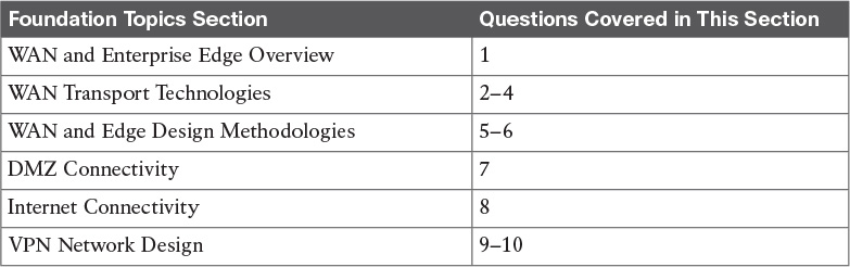
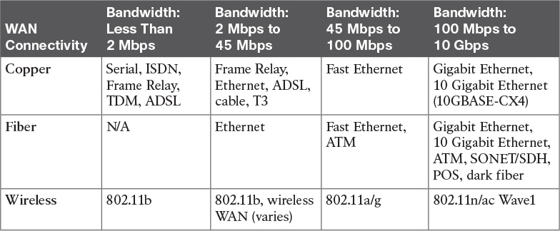
Table 6-2 examines some WAN technologies and highlights some common factors used to make WAN technology selections. This information also reflects the different characteristics of each WAN technology. However, keep in mind that your service provider offerings limit the WAN technology choices available to you during your selection.
The following sections offer more details about each WAN technology covered in Table 6-2.
ISDN
Integrated Services Digital Network (ISDN) is an all-digital phone line connection that was standardized in the early 1980s. ISDN allows both voice and data to be transmitted over the digital phone line instead of the analog signals used in dialup connections. ISDN provides greater bandwidth and lower latency compared to dialup analog technology. ISDN comes in two service types: Basic Rate Interface (BRI) and Primary Rate Interface (PRI).
ISDN BRI Service
ISDN BRI consists of two B channels and one D channel (2B+D). Both of the BRI B channels operate at 64 Kbps and carry user data. The D channel handles the signaling and control information and operates at 16 Kbps. Another 48 Kbps is used for framing and synchronization, for a total bit rate of 192 Kbps.
ISDN PRI Service
ISDN PRI service offers 23 B channels and 1 D channel (23B+D) in both North America and Japan. Each channel (including the D channel) operates at 64 Kbps, for a total bit rate of 1.544 Mbps, including overhead. In other parts of the world, such as Europe and Australia, the ISDN PRI service provides 30 B channels and 1 64Kbps D channel.
Although ISDN has been around for many years, the industry has moved toward using broadband technologies such as cable, DSL, and public wireless with IPsec VPNs for WAN services. However, ISDN PRI still remains as an effective UC solution used for terminating voice circuits on voice gateway routers.
Digital Subscriber Line
Digital subscriber line (DSL) is a technology that provides high-speed Internet data services over ordinary copper telephone lines. It achieves this by using frequencies that are not used in normal voice telephone calls.
The term xDSL describes the various competing forms of DSL available today.
ADSL is the most popular DSL technology and is widely available. The key to ADSL is that the downstream bandwidth is asymmetric or higher than the upstream bandwidth. Some limitations include that ADSL can be used only in close proximity to the local DSLAM, typically less than 2 km. The local DSLAM, or digital subscriber line access multiplexer, allows telephone lines to make DSL connections to the Internet. Download speeds usually range from 768 Kbps to 9 Mbps, and upload speeds range from 64 Kbps to 1.5 Mbps. The customer premises equipment (CPE) refers to a PC along with a DSL modem or DSL router that connects back to the network access provider (NAP) DSLAMs.
The ADSL circuit consists of a twisted-pair telephone line that contains three information channels:
![]() Medium-speed downstream channel
Medium-speed downstream channel
![]() Low-speed upstream channel
Low-speed upstream channel
![]() Basic telephone service channel
Basic telephone service channel
DSL splitters are used to separate basic telephone service from the ADSL modem/router to provide service even if the ADSL signaling fails.
Although DSL is primarily used in the residential community, this technology can also be used as a WAN technology for an organization. However, keep in mind that because this is a public network connection over the Internet, it is recommended that this technology be used in conjunction with a firewall/VPN solution back into your corporate enterprise network. The high speeds and relatively low cost make this a popular Internet access WAN technology.
Cable
Broadband cable is a technology used to transport data using a coaxial cable medium over cable distribution systems. The equipment used on the remote-access side or customer premises is the cable modem, and it connects to the Cable Modem Termination System (CMTS) on the ISP side. The Universal Broadband Router (uBR) or CMTS provides the CMTS services, which forward traffic upstream through the provider’s Internet connections.
Cable modems support data, voice, and video TCP/IP traffic. Generally, cable modems are installed at the customer premises to provide service to small businesses, branch offices, and corporate teleworkers.
The Data Over Cable Service Interface Specifications (DOCSIS) protocol defines the cable procedures that the equipment needs to support.
Figure 6-3 illustrates how a cable modem connects to the CMTS. The PC connects to the TCP/IP network using PPP over Ethernet (PPPoE) or Dynamic Host Configuration Protocol (DHCP).

Wireless
Wireless as a technology uses electromagnetic waves to carry the signal between endpoints. Everyday examples of wireless technology include cell phones, wireless LANs, cordless computer equipment, and global positioning systems (GPS).
Here are some examples of wireless implementations:
![]() Bridge wireless: Wireless bridges connect two separate networks, typically located in two separate buildings. This technology enables high data rates for use with line-of-sight applications. When interconnecting hard-to-wire sites, temporary networks, or warehouses, a series of wireless bridges can be connected to provide connectivity.
Bridge wireless: Wireless bridges connect two separate networks, typically located in two separate buildings. This technology enables high data rates for use with line-of-sight applications. When interconnecting hard-to-wire sites, temporary networks, or warehouses, a series of wireless bridges can be connected to provide connectivity.
![]() Wireless LAN: WLANs have increased, too, in both residential and business environments to meet the demands of LAN connections over the air. Wi-Fi networks are based on IEEE 802.11a/b/g/n standards or the newest 802.11ac Wave 1 standard, providing data rates up to 1.3 Gbps. The growing range of applications includes guest access, voice over wireless, advanced security, and location-based services. A key advantage of WLANs is the ability to save time and money by avoiding costly physical layer wiring installations.
Wireless LAN: WLANs have increased, too, in both residential and business environments to meet the demands of LAN connections over the air. Wi-Fi networks are based on IEEE 802.11a/b/g/n standards or the newest 802.11ac Wave 1 standard, providing data rates up to 1.3 Gbps. The growing range of applications includes guest access, voice over wireless, advanced security, and location-based services. A key advantage of WLANs is the ability to save time and money by avoiding costly physical layer wiring installations.
![]() Mobile wireless: Consists of cellular applications and mobile phones. Most wireless technologies, such as the second and third generations, are migrating to more digital services to take advantage of the higher speeds. Mobile wireless technologies include GSM, GPRS, and UMTS:
Mobile wireless: Consists of cellular applications and mobile phones. Most wireless technologies, such as the second and third generations, are migrating to more digital services to take advantage of the higher speeds. Mobile wireless technologies include GSM, GPRS, and UMTS:
![]() GSM: Global System for Mobile Communications. A digital mobile radio standard that uses time-division multiplex access (TDMA) technology in three bands (900, 1800, and 1900 MHz). The data transfer rate is 9600 bps and includes the ability to roam internationally.
GSM: Global System for Mobile Communications. A digital mobile radio standard that uses time-division multiplex access (TDMA) technology in three bands (900, 1800, and 1900 MHz). The data transfer rate is 9600 bps and includes the ability to roam internationally.
![]() GPRS: General Packet Radio Service. Extends the capability of GSM speeds from 64 Kbps to 128 Kbps.
GPRS: General Packet Radio Service. Extends the capability of GSM speeds from 64 Kbps to 128 Kbps.
![]() UMTS: Universal Mobile Telecommunications Service. Also known as 3G broadband. Provides packet-based transmission of digitized voice, video, and data at rates up to 2.0 Mbps. UMTS also provides a set of services available to mobile users, location-independent throughout the world.
UMTS: Universal Mobile Telecommunications Service. Also known as 3G broadband. Provides packet-based transmission of digitized voice, video, and data at rates up to 2.0 Mbps. UMTS also provides a set of services available to mobile users, location-independent throughout the world.
![]() LTE: Long Term Evolution, also known as 4G LTE. Based on GSM and UMTS network technologies, but increases the capacity and speed using a different radio along with network improvements. Download peak rates are up to 300 Mbps and upload peak rates are up to 75 Mbps.
LTE: Long Term Evolution, also known as 4G LTE. Based on GSM and UMTS network technologies, but increases the capacity and speed using a different radio along with network improvements. Download peak rates are up to 300 Mbps and upload peak rates are up to 75 Mbps.
Figure 6-4 shows examples of bridge wireless and wireless LANs.

Frame Relay
Frame Relay is a packet-switched connection-oriented Layer 2 WAN protocol. Frame Relay is an industry standard networking protocol that uses virtual circuits between connected devices. The data link layer in Frame Relay establishes connections using a DTE device such as a router and a DCE device such as a frame switch.
Frame Relay circuits between sites can be either permanent virtual circuits (PVCs) or switched virtual circuits (SVCs). PVCs are used more predominantly because of the connections’ permanent nature. SVCs, on the other hand, are temporary connections created for each data transfer session.
A point-to-point PVC between two routers or endpoints uses a data-link connection identifier (DLCI) to identify the local end of the PVC. The DLCI is a locally significant numeric value that can be reused throughout the Frame Relay WAN if necessary.
Frame Relay has been deployed since the late 1980s, but the use of Frame Relay is on the decline because of the popularity of MPLS.
Time-Division Multiplexing
Time-division multiplexing (TDM) is a type of digital multiplexing in which multiple channels such as data, voice, and video are combined over one communication medium by interleaving pulses representing bits from different channels. Basic DS0 channel bandwidth is defined at 64 Kbps. In North America, a DS1 or T1 circuit provides 1.544 Mbps of bandwidth consisting of 24 time slots of 64 Kbps each and an 8Kbps channel for control information. In addition, a DS3 or T3 circuit provides 44.736 Mbps of bandwidth. Other parts of the world, such as Europe, follow E1 standards, which allow for 30 channels at 2.048 Mbps of bandwidth. Service providers can guarantee or reserve the bandwidth used on TDM networks. The customers’ TDM transmissions are charged for their exclusive access to these circuits. On the other hand, packet-switched networks typically are shared, thereby allowing the service providers more flexibility in managing their networks and the services they offer.
Metro Ethernet
Metro Ethernet uses well-known “Ethernet” to deliver low-cost and high-speed MAN/WAN connectivity for organizations. Many service providers now offer Metro Ethernet solutions to deliver a wide range of converged network services such as data, voice, and video on the same wire. Metro Ethernet provides enterprise LAN type functionality out in the MAN and WAN, increasing the throughput available for applications. Metro Ethernet bandwidths can range from 100 Mbps to 10 Gbps, and even higher in some cases, allowing for support for higher performance and increased QoS requirements. In contrast to the rigid nature of traditional TDM provisioning, metro Ethernet services are much easier to deploy and scale due to the flexible bandwidth increments. Metro Ethernet technology is appealing to many customers because they are already comfortable using Ethernet throughout their LAN environments.
SONET/SDH
The architecture of SONET/SDH is circuit based and delivers high-speed services over an optical network. SONET is defined by the American National Standards Institute (ANSI) specification, and the International Telecommunications Union (ITU) defines SDH. SONET/SDH guarantees bandwidth and has line rates of 155 Mbps to more than 10 Gbps. Common circuit sizes are OC-3, or 155 Mbps, and OC-12, or 622 Mbps.
SONET/SDH uses a ring topology by connecting sites and providing automatic recovery capabilities and has self-healing mechanisms. SONET/SDH rings support ATM or Packet over SONET (POS) IP encapsulations. The Optical Carrier (OC) rates are the digital bandwidth hierarchies that are part of the SONET/SDH standards. The optical carrier speeds supported are as follows:
![]() OC-1 = 51.85 Mbps
OC-1 = 51.85 Mbps
![]() OC-3 = 155.52 Mbps
OC-3 = 155.52 Mbps
![]() OC-12 = 622.08 Mbps
OC-12 = 622.08 Mbps
![]() OC-24 = 1.244 Gbps
OC-24 = 1.244 Gbps
![]() OC-48 = 2.488 Gbps
OC-48 = 2.488 Gbps
![]() OC-192 = 9.952 Gbps
OC-192 = 9.952 Gbps
![]() OC-255 = 13.21 Gbps
OC-255 = 13.21 Gbps
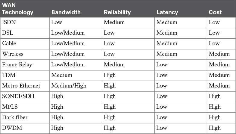
Figure 6-5 shows an OC-48 SONET ring with connections to three sites that share the ring.
Multiprotocol Label Switching (MPLS)
MPLS is technology for the delivery of IP services using labels (numbers) to forward packets. In normal routed environments, packets are forwarded hop by hop from the sources to the destination. Each router in the path performs a Layer 3 destination address lookup, rewrites the Layer 2 address, and forwards the packet to the destination. However, MPLS functions by marking packet headers that include label information. As soon as packets are marked with a label, specific paths through the network can be designed to correspond to that distinct label. MPLS labels can be set on parameters such as source addresses, Layer 2 circuit ID, or QoS value. Packets that are destined to the same endpoint with the same requirements can be forwarded based on the labels, without a routing decision at every hop. Typically, the labels correspond to the Layer 3 destination address, which makes MPLS the same as destination-based routing.
MPLS labels can also be used to implement traffic engineering by overriding the routing tables. MPLS packets can run over most Layer 2 technologies, such as ATM, Frame Relay, POS, and Ethernet. The goal of MPLS is to maximize switching using labels and minimize Layer 3 routing.
In MPLS implementations, there are customer edge (CE) routers, provider edge (PE) routers, and provider (P) routers. The CE router resides at the customer premises, and that is typically where internal and external routing information is exchanged. The CE router then connects to the PE router, which is the ingress to the MPLS service provider network. After that, the PE routers connect to P routers in the core of the service provider network. To exit the MPLS network, the process is reversed, with the last router being the CE router at the other customer premises.
Figure 6-6 shows the end-to-end MPLS WAN connectivity with CE, PE, and P routers.

Dark Fiber
Dark fiber is fiber-optic cable that has been installed in the ground or where right-of-way issues are evident. To maintain signal integrity and jitter control over long distances, signal regenerators are used in some implementations. The framing for dark fiber is determined by the enterprise, not the provider. The edge devices can use the fiber just like within the enterprise, which allows for greater control of the services provided by the link. Dark fiber is owned by service providers in most cases and can be purchased similarly to leased-line circuits for use in both the MAN and WAN. The reliability of these types of links also needs to be designed by the enterprise and is not provided by the service provider. High availability using dark fiber needs to be designed with multiple links, which differs from SONET/SDH technology that has redundancy built into the architecture.
Dense Wavelength-Division Multiplexing
Dense wavelength-division multiplexing (DWDM) increases fiber optic’s bandwidth capabilities by using different wavelengths of light called channels over the same fiber strand. Each fiber channel is the equivalent to several (Nx) 10 Gigabit Ethernet links. It maximizes the use of the installed base of fiber used by service providers and is a critical component of optical networks. DWDM allows for service providers to increase the services offered to customers by adding new bandwidth to existing channels on the same fiber. DWDM lets a variety of devices access the network, including IP routers, ATM switches, and SONET terminals.
Figure 6-7 illustrates the use of DWDM using Cisco Nexus and Cisco ONS devices with a SONET/SDH ring.

Ordering WAN Technology and Contracts
When you order WAN transport technology, early planning is key. It usually takes at least 60 days for the carrier to provision circuits. Generally, the higher a circuit’s capacity, the more lead time required to provision. When ordering bandwidth overseas or between hemispheres, a lead time of 60 to 120 days is fairly common.
WAN transport in most cases includes an access circuit charge and, at times, distance-based charges. However, some carriers have eliminated TDM distance-based charges because T1s are readily available from most carriers. Metro Ethernet availability is spotty at best, and the lead times are long. In rare cases, construction is necessary to provide fiber access, which requires more cost and time delays. You should compare pricing and available WAN technology options from competing carriers.
When ordering Frame Relay and ATM, a combination of access circuit charges, per-PVC charges, and per-bandwidth committed information rate (CIR) charges are customary. CIR is the rate the provider guarantees it will provide. Some carriers set the CIR to half the circuit’s speed, thereby allowing customers to burst two times above the CIR. Frame Relay speeds can be provisioned up to T3 speeds, but typically they are less than 10 Mbps.
MPLS VPNs have been competitive with ATM and Frame Relay rates. Service providers are offering MPLS VPNs with higher bandwidth at lower rates to persuade their customers away from traditional ATM and Frame Relay services. However, other service providers see more value in MPLS VPNs and price them higher than ATM and Frame Relay because of the added benefits of traffic engineering. Some carriers charge more for additional CoS queues, so it is important to design the proper amount of CoS queues, factoring in room for growth.
When you are selecting a standard carrier package, it takes about a month to contract a WAN circuit. If you want to negotiate a detailed SLA, expect to take another five months or more, including discussions with the service provider’s legal department. The bigger the customer, the more influence it has over the SLAs and the contract negotiations.
Contract periods for most WAN services are one to five years. Contracts are usually not written for longer durations because of the new emerging technologies and better offerings from providers. An exception is dark fiber, which is usually contracted for a 20-year term. In this case, you also want to have the right of non-reversion written in the SLA. This means that no matter what happens to the service provider, the fiber is yours for the 20-year period. The process to repair fiber cuts needs to be defined in the SLA.
Tariffed commercial WAN services are available at published rates but are subject to restrictions. However, carriers are moving toward unpublished rates to be more competitive and to offer more options.
WAN and Edge Design Methodologies
The Plan, Build, and Manage methodology should be used when designing enterprise edge networks. Some keys to PBM are the processes of identifying business and technology strategies, assessing the existing network, and creating a design that is scalable, flexible, and resilient:
![]() Identifying the network requirements includes reviewing the types of applications, the traffic volume, and the traffic patterns in the network.
Identifying the network requirements includes reviewing the types of applications, the traffic volume, and the traffic patterns in the network.
![]() Assessing the existing network reviews the technologies used and the locations of hosts, servers, network equipment, and other end nodes.
Assessing the existing network reviews the technologies used and the locations of hosts, servers, network equipment, and other end nodes.
![]() Designing the topology is based on the availability of technology as well as the projected traffic patterns, technology performance, constraints, and reliability.
Designing the topology is based on the availability of technology as well as the projected traffic patterns, technology performance, constraints, and reliability.
When designing the WAN topology, remember that the design should describe the functions that the enterprise modules should perform. The expected service levels provided by each WAN technology should be explained. WAN connections can be characterized by the cost of renting the transmission media from the service provider to connect two or more sites together.
New network designs should be flexible and adaptable to future technologies and should not limit the customer’s options going forward. Voice over IP and video are examples of technologies that network designs should be able to support if the customer decides to move to a converged network. The customer should not have to undergo major hardware upgrades to implement these types of technologies. In addition, the ongoing support and management of the network is another important factor, along with the design’s cost-effectiveness.
Table 6-3 lists key design principles that can help serve as the basis for developing network designs.

High availability is often what most businesses and organizations strive for in sound network designs. The key components of application availability are response time, throughput, and reliability. Real-time applications such as voice and video are not very tolerant to jitter and delay.
Table 6-4 identifies various application requirements for data, voice, and video traffic.

Response Time
Response time measures the time between the client user request and the response from the server host. The end user will accept a certain level of delay in response time and still be satisfied. However, there is a limit to how long the user will wait. This amount of time can be measured and serves as a basis for future application response times. Users perceive the network communication in terms of how quickly the server returns the requested information and how fast the screen updates. Some applications, such as a request for an HTML web page, require short response times. On the other hand, a large FTP transfer might take a while, but this is generally acceptable.
Throughput
In network communications, throughput is the measure of data transferred from one host to another in a given amount of time. Bandwidth-intensive applications have more of an impact on a network’s throughput than interactive traffic such as a Telnet session. Most high-throughput applications usually involve some type of file-transfer activity. Because throughput-intensive applications have longer response times, you can usually schedule them when time-sensitive traffic volumes are lower, such as after hours.
Reliability
Reliability is the measure of a given application’s availability to its users. Some organizations require rock-solid application reliability, such as five-nines (99.999 percent); this has a higher price than most other applications. For example, financial and security exchange commissions require nearly 100 percent uptime for their applications. These types of networks are built with a high amount of physical and logical redundancy. It is important to ascertain the level of reliability needed for a network that is being designed. Reliability goes further than availability by measuring not only whether the service is there but whether it is performing as it should.
Bandwidth Considerations
Table 6-5 compares a number of different WAN technologies, along with the speeds and media types associated with them.
The WAN designer must engineer the network with enough bandwidth to support the needs of the users and applications that will use the network. How much bandwidth a network needs depends on the services and applications that will require network bandwidth. For example, VoIP requires more bandwidth than interactive Secure Shell (SSH) traffic. A large number of graphics or CAD drawings require an extensive amount of bandwidth compared to file or print sharing information being transferred on the network. A big driver in increasing demands for more bandwidth is the expanded use of collaboration applications that use video interactively.
When designing bandwidth for the WAN, remember that implementation and recurring costs are always important factors. It is best to begin planning for WAN capacity early. When the link utilization reaches around 50 percent to 60 percent, you should consider increases and closely monitor the capacity at that point. When the link utilization reaches around 75 percent, immediate attention is required to avoid congestion problems and packet loss that will occur when the utilization nears full capacity.
QoS techniques become increasingly important when delay-sensitive traffic such as VoIP is using the limited bandwidth available on the WAN. LAN bandwidth, on the other hand, is generally inexpensive and plentiful; in the age of robust real-time applications, however, QoS can be necessary. To provide connectivity on the LAN, you typically need to be concerned only with hardware and implementation costs.
WAN Link Categories
When you start to evaluate WAN link characteristics, they generally fall into three broad categories: private, leased, and shared. There are many factors to consider, such as how the WAN is used, the cost, advantages, and what technologies are available in a given area.
Table 6-6 identifies various WAN link characteristics.
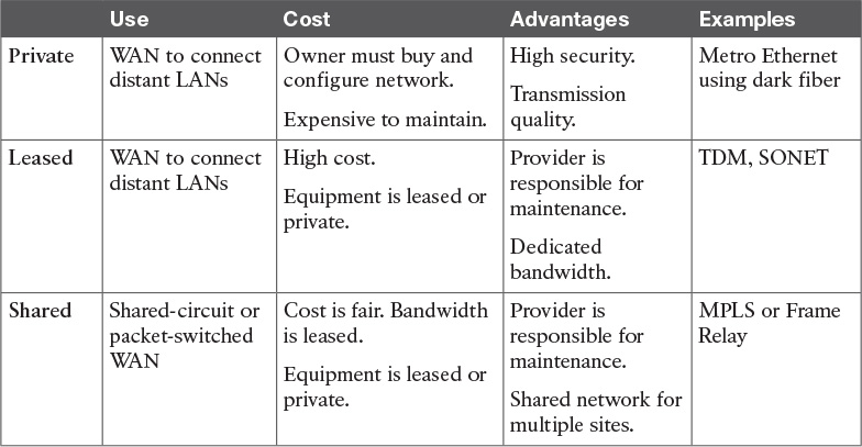
There are fixed and recurring costs in most WAN environments. Fixed costs include the network equipment, circuit provisioning, and network management tools. The recurring costs include the service provider monthly WAN service fees, maintenance costs of the WAN, and the network operations personnel.
Optimizing Bandwidth Using QoS
QoS is an effective tool for managing a WAN’s available bandwidth. Keep in mind that QoS does not add bandwidth; it only helps you make better use of it. For chronic congestion problems, QoS is not the answer; you need to add more bandwidth. However, by prioritizing traffic, you can make sure that your most critical traffic gets the best treatment and available bandwidth in times of congestion. One popular QoS technique is to classify your traffic based on a protocol type or a matching access control list (ACL) and then give policy treatment to the class. You can define many classes to match or identify your most important traffic classes. The remaining unmatched traffic then uses a default class in which the traffic can be treated as best effort.
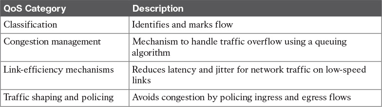
Queuing, Traffic Shaping, and Policing
Cisco has developed many different QoS mechanisms, such as queuing, policing, and traffic shaping, to enable network operators to manage and prioritize the traffic flowing on the network. Applications that are delay sensitive, such as VoIP, require special treatment to ensure proper application functionality. Queuing refers to the buffering process used by routers and switches when they receive traffic faster than can be transmitted. Different queuing mechanisms can be implemented to influence the order in which the different queues are serviced (that is, how different types of traffic are emptied from the queues).
Table 6-7 identifies QoS considerations to optimize bandwidth.
Classification
For a flow to have priority, it first must be identified and marked. Both of these tasks are referred to as classification. The following technologies have features that support classification:
![]() Network-based application recognition (NBAR) is a technology that uses deep packet content inspection to identify network applications. An advantage of NBAR is that it can recognize applications even when they do not use standard network ports. Furthermore, it matches fields at the application layer. Before NBAR, classification was limited to Layer 4 TCP and User Datagram Protocol (UDP) port numbers.
Network-based application recognition (NBAR) is a technology that uses deep packet content inspection to identify network applications. An advantage of NBAR is that it can recognize applications even when they do not use standard network ports. Furthermore, it matches fields at the application layer. Before NBAR, classification was limited to Layer 4 TCP and User Datagram Protocol (UDP) port numbers.
![]() Committed access rate (CAR) uses an ACL to set precedence and allows customization of the precedence assignment by user, source or destination IP address, and application type.
Committed access rate (CAR) uses an ACL to set precedence and allows customization of the precedence assignment by user, source or destination IP address, and application type.
Congestion Management
Two types of output queues are available on routers: the hardware queue and the software queue. The hardware queue uses the strategy of first in, first out (FIFO). The software queue schedules packets first and then places them in the hardware queue. Keep in mind that the software queue is used only during periods of congestion. The software queue uses QoS techniques such as priority queuing, custom queuing, weighted fair queuing, class-based weighted fair queuing, low-latency queuing, and traffic shaping and policing.
Priority Queuing
Priority queuing (PQ) is a queuing method that establishes four interface output queues that serve different priority levels: high, medium, default, and low. Unfortunately, PQ can starve other queues if too much data is in one queue because higher-priority queues must be emptied before lower-priority queues.
Custom Queuing
Custom queuing (CQ) uses up to 16 individual output queues. Byte size limits are assigned to each queue so that when the limit is reached, it proceeds to the next queue. The network operator can customize these byte size limits. CQ is fairer than PQ because it allows some level of service to all traffic. This queuing method is considered legacy due to the improvements in the queuing methods.
Weighted Fair Queuing
Weighted fair queuing (WFQ) ensures that traffic is separated into individual flows or sessions without requiring that you define ACLs. WFQ uses two categories to group sessions: high bandwidth and low bandwidth. Low-bandwidth traffic has priority over high-bandwidth traffic. High-bandwidth traffic shares the service according to assigned weight values. WFQ is the default QoS mechanism on interfaces below 2.0 Mbps.
Class-Based Weighted Fair Queuing
Class-based weighted fair queuing (CBWFQ) extends WFQ capabilities by providing support for modular user-defined traffic classes. CBWFQ lets you define traffic classes that correspond to match criteria, including ACLs, protocols, and input interfaces. Traffic that matches the class criteria belongs to that specific class. Each class has a defined queue that corresponds to an output interface.
After traffic has been matched and belongs to a specific class, you can modify its characteristics, such as assigning bandwidth, maximum queue limit, and weight. During periods of congestion, the bandwidth assigned to the class is the guaranteed bandwidth that is delivered to the class.
One of CBWFQ’s key advantages is its modular nature, which makes it extremely flexible for most situations. It is often referred to as MQC, or Modular QoS CLI, which is the framework for building QoS policies. Many classes can be defined to separate your network traffic as needed in the MQC.
Low-Latency Queuing
Low-latency queuing (LLQ) adds a strict priority queue (PQ) to CBWFQ. The strict PQ allows delay-sensitive traffic such as voice to be sent first, before other queues are serviced. That gives voice preferential treatment over the other traffic types. Unlike priority queuing, LLQ provides for a maximum threshold on the PQ to prevent lower priority traffic from being starved by the PQ.
Without LLQ, CBWFQ would not have a priority queue for real-time traffic. The additional classification of other traffic classes is done using the same CBWFQ techniques. LLQ is the standard QoS method for many VoIP networks.
Traffic Shaping and Policing
Traffic shaping and policing are mechanisms that inspect traffic and take an action based on the traffic’s characteristics, such as DSCP or IP precedence bits set in the IP header.
Traffic shaping slows down the rate at which packets are sent out an interface (egress) by matching certain criteria. Traffic shaping uses a token bucket technique to release the packets into the output queue at a preconfigured rate. Traffic shaping helps eliminate potential bottlenecks by throttling back the traffic rate at the source. In enterprise environments, traffic shaping is used to smooth the flow of traffic going out to the provider. This is desirable for several reasons. In provider networks, it prevents the provider from dropping traffic that exceeds the contracted rate.
Policing tags or drops traffic depending on the match criteria. Generally, policing is used to set the limit of incoming traffic coming into an interface (ingress) and uses a “leaky bucket mechanism.” Policing is also referred to as committed access rate, or CAR. One example of using policing is to give preferential treatment to critical application traffic by elevating to a higher class and reducing best-effort traffic to a lower-priority class.
When you contrast traffic shaping with policing, remember that traffic shaping buffers packets while policing can be configured to drop packets. In addition, policing propagates bursts, but traffic shaping does not.
Link Efficiency
Within Cisco IOS, several link-efficiency mechanisms are available. Link fragmentation and interleaving (LFI), Multilink PPP (MLP), and Real-Time Transport Protocol (RTP) header compression provide for more efficient use of available bandwidth.
Table 6-8 describes Cisco IOS link-efficiency mechanisms.

Window Size
The window size defines the upper limit of frames that can be transmitted without getting a return acknowledgment. Transport protocols, such as TCP, rely on acknowledgments to provide connection-oriented reliable transport of data segments. For example, if the TCP window size is set to 8192, the source stops sending data after 8192 bytes if no acknowledgment has been received from the destination host. In some cases, the window size might need to be modified because of unacceptable delay for larger WAN links. If the window size is not adjusted to coincide with the delay factor, retransmissions can occur, which affects throughput significantly. It is recommended that you adjust the window size to achieve better connectivity conditions.
DMZ Connectivity
Inside the enterprise edge module, the main purpose of DMZs is to provide access to services through control and isolation techniques. Firewalls are used to segment the DMZs by function (Internet DMZ or remote access VPN DMZ, for example). DMZs are typically segmented and controlled by ACLs on stateful firewalls such as Cisco ASA. In addition, security controls such as virtual devices contexts, NAT, proxying, and split routing/DNS can also be used to enforce enhanced levels of security. Services within the DMZs can be hosted on physical or virtual appliances located in the data center.
DMZ types include the following:
![]() Internet DMZ: These types of DMZs provide Internet-facing services such as web, email, DNS, and e-commerce services for corporate users and/or customers.
Internet DMZ: These types of DMZs provide Internet-facing services such as web, email, DNS, and e-commerce services for corporate users and/or customers.
![]() Remote access VPN DMZ: DMZ for network access by corporate users via SSL or IPsec VPN sessions.
Remote access VPN DMZ: DMZ for network access by corporate users via SSL or IPsec VPN sessions.
![]() Site-to-site VPN DMZ: DMZ for remote site or branch office connectivity via IPsec VPN tunnels as an alternative to private network WAN service.
Site-to-site VPN DMZ: DMZ for remote site or branch office connectivity via IPsec VPN tunnels as an alternative to private network WAN service.
![]() Cloud services DMZ: DMZ to connect to public cloud services such as Amazon Web Services (AWS) or Microsoft Azure via encrypted tunnels.
Cloud services DMZ: DMZ to connect to public cloud services such as Amazon Web Services (AWS) or Microsoft Azure via encrypted tunnels.
![]() Unified communications DMZ: DMZ to host UC services such as voice and video over the Internet.
Unified communications DMZ: DMZ to host UC services such as voice and video over the Internet.
![]() Security services DMZ: Security-based DMZ for services such as web application firewalls (WAPs), intrusion prevention services (IPSs), email, and URL filtering services.
Security services DMZ: Security-based DMZ for services such as web application firewalls (WAPs), intrusion prevention services (IPSs), email, and URL filtering services.
Figure 6-8 depicts the use of FW DMZs with access control entries (ACEs) in the enterprise edge.

Segmenting DMZs
The primary method of segmenting DMZs takes advantage of using separate physical or logical interfaces on a firewall. In addition, it is important to consider dedicating DMZs per service and even dividing up critical services into multiple DMZs, thereby increasing security. These levels of classification reduce the risk of compromise by splitting up the services. There is also an increased use of virtual machines and virtual appliances that need to be leveraged that reside in the data center infrastructure. From the enterprise edge, additional segmentation techniques such as VLANs, VRFs, IPsec VPNs, and virtual device contexts can be used to extend the traffic and provide path isolation.
Figure 6-9 illustrates the use of a virtual appliance in the data center being used in the public-facing DMZ.

DMZ Services
When designing DMZs, you have two main options for distributing the DMZ services—per-service DMZs and shared DMZs. When considering which one to use, think about how each option will impact the management and security of the network. For example, too many DMZs will increase security but will also increase the management overhead. Balancing cost versus risk in order to meet the business requirements will help you determine what is right for the organization.
![]() Per-service DMZ: Good for traffic isolation and security because all traffic will have to go through the firewall, but there is an impact on management and performance.
Per-service DMZ: Good for traffic isolation and security because all traffic will have to go through the firewall, but there is an impact on management and performance.
![]() Shared DMZs: More services in a DMZ will ease the management overhead and performance, but also will decrease the security because all of the traffic is locally switched. However, you can use enhanced Layer 2 features such as port security and private VLANs to further increase security.
Shared DMZs: More services in a DMZ will ease the management overhead and performance, but also will decrease the security because all of the traffic is locally switched. However, you can use enhanced Layer 2 features such as port security and private VLANs to further increase security.
Internet Connectivity
Most enterprises have multiple sites with a varying number of users at each site, but are usually grouped into two site types: larger central sites and smaller branch sites. The larger site types will typically host more of the users and services. The smaller branch offices will have a low user count and a smaller number of hosted services. Both central and branch sites typically need Internet access, but there are high availability considerations to think about when selecting the Internet access design for a given site type. When choosing an Internet connectivity option, remember to take into account the business requirements and the budget allocated for the design.
Internet connectivity options include the following:
Dual-router dual-homed: Provides the highest level of resiliency for Internet connectivity with full redundancy in hardware, links, and Internet service providers.
Single-router dual-homed: Provides a good level of redundancy for the Internet connectivity through the use of multiple links and multiple Internet service providers.
Single-router single-homed: Provides the bare minimum for Internet connectivity, providing no levels of redundancy for the hardware, links, or Internet service providers.
Figure 6-10 shows Internet connectivity options with different levels of redundancy.

Because central sites have higher user populations, they will normally have higher Internet bandwidth connectivity and centralized access control for the Internet traffic flows. Although most branch offices will have an Internet connection, many of them will still have their Internet traffic backhauled over the WAN to the central site where centralized access control can occur. Another Internet connectivity option for branches sites is to have their own direct Internet access, but there are security challenges with adhering to the same set of security policies in place at the centralized site. Even though the performance for the traffic flows is better with direct Internet access, there is a greater security risk for the enterprise due to more Internet connection points for attackers to target.
Centralized Internet (Branch) vs. Direct Internet (Branch)
Whether or not to backhaul Internet traffic from branch offices versus branches having direct Internet is a common decision that many companies now need to face. Here are some pros and cons of each:
![]() Centralized Internet for each branch: Higher bandwidth available and centralized security policies, but suboptimal traffic flows. This might require additional redundancy at the Internet edge, which may or may not be present.
Centralized Internet for each branch: Higher bandwidth available and centralized security policies, but suboptimal traffic flows. This might require additional redundancy at the Internet edge, which may or may not be present.
![]() Direct Internet for branches: Optimal traffic flows, but more difficult to manage distributed security policies. This also has a higher risk of Internet attacks due to more attachment points.
Direct Internet for branches: Optimal traffic flows, but more difficult to manage distributed security policies. This also has a higher risk of Internet attacks due to more attachment points.
High Availability for the Internet Edge
Once you have decided on having two Internet routers, each with a link to two different Internet service providers, it is time to start thinking about the logical design for the routers. Logical Internet HA design considerations include the following:
![]() Use a public BGP AS number for EBGP connections to the ISPs.
Use a public BGP AS number for EBGP connections to the ISPs.
![]() Use provider-independent IP address space to allow for advertisement to both ISPs.
Use provider-independent IP address space to allow for advertisement to both ISPs.
![]() Receive full or partial Internet routing tables to optimize forwarding outbound.
Receive full or partial Internet routing tables to optimize forwarding outbound.
![]() Use HSRP/GLBP or an IGP such as EIGRP or OSPF internally.
Use HSRP/GLBP or an IGP such as EIGRP or OSPF internally.
VPN Network Design
VPNs are typically deployed over some kind of shared or public infrastructure. VPNs are similar to tunnels in that they carry traffic over an existing IP infrastructure. VPN technologies use the Internet, ATM/Frame Relay WANs, and point-to-point connected IP infrastructures to transport data from end to end. A disadvantage of using VPNs over public networks is that the connectivity is best effort in nature, and troubleshooting is also difficult because you do not have visibility into the service provider’s infrastructure.
One of the goals of remote-access network design is to provide a unified solution that allows for seamless connectivity as if the users are on the HQ LAN. The primary function of remote access is to provide your users access to internal resources and applications. Because connection requirements drive the technology selection process, it is important that you analyze the application and network requirements in addition to reviewing the available service provider options.
The following summarizes typical remote-access requirements:
![]() Best-effort interactive and low-volume traffic patterns
Best-effort interactive and low-volume traffic patterns
![]() Connections to the enterprise edge using Layer 2 WAN technologies (consider capital and recurring costs)
Connections to the enterprise edge using Layer 2 WAN technologies (consider capital and recurring costs)
![]() Voice and IPsec VPN support
Voice and IPsec VPN support
Remote-access network connections are enabled over permanent always-on connections or on-demand connections. Technologies include any Internet connection technology such as cable, wireless 802.11 a/b/g/n LAN, and 3G/4G wireless WAN (WWAN). However, these remote-access technologies might or might not be available, so it is best to check the availability for the location in your network design.
VPN types divided by application, include the following:
![]() Remote access VPN: These types of VPN connections give mobile users, home users, and partners connectivity to corporate intranets over the Internet. Users typically connect remotely using cable, wireless LAN, or 3G/4G WWAN. Remote access VPNs usually terminate on Cisco ASA appliances and can be grouped together to form a load-balancing cluster in a dedicated DMZ, or existing Cisco ASA firewalls can be used in smaller organizations. Both SSL and IPsec protocols are supported with remote access VPNs, but SSL is recommended. With an SSL VPN, client design options include full tunnel or split tunnel, local LAN access, a web or Anyconnect client, an authentication mechanism, and endpoint assessments, all enforced by the ASA appliance.
Remote access VPN: These types of VPN connections give mobile users, home users, and partners connectivity to corporate intranets over the Internet. Users typically connect remotely using cable, wireless LAN, or 3G/4G WWAN. Remote access VPNs usually terminate on Cisco ASA appliances and can be grouped together to form a load-balancing cluster in a dedicated DMZ, or existing Cisco ASA firewalls can be used in smaller organizations. Both SSL and IPsec protocols are supported with remote access VPNs, but SSL is recommended. With an SSL VPN, client design options include full tunnel or split tunnel, local LAN access, a web or Anyconnect client, an authentication mechanism, and endpoint assessments, all enforced by the ASA appliance.
![]() Site-to-site VPN: Site-to-site VPNs over the Internet offer an alternative WAN transport for interconnecting sites. Generally, the remote sites use their Internet connection to establish the VPN connection back to the corporate head-end office. Site-to-site VPNs can also use an IP backbone provided by the service provider. The main use cases for site-to-site VPNs are for primary WAN transport, lower-cost MPLS WAN backup, and connecting to secure cloud services. ASAs, Cisco ISR, and Cisco ASR series routers are commonly used for site-to-site VPNs with IPsec over GRE to support the deployment of IGPs.
Site-to-site VPN: Site-to-site VPNs over the Internet offer an alternative WAN transport for interconnecting sites. Generally, the remote sites use their Internet connection to establish the VPN connection back to the corporate head-end office. Site-to-site VPNs can also use an IP backbone provided by the service provider. The main use cases for site-to-site VPNs are for primary WAN transport, lower-cost MPLS WAN backup, and connecting to secure cloud services. ASAs, Cisco ISR, and Cisco ASR series routers are commonly used for site-to-site VPNs with IPsec over GRE to support the deployment of IGPs.
![]() Extranet VPNs: This is another form of site-to-site VPN infrastructure for business partner connectivity that also uses the Internet or a private infrastructure for network access. Keep in mind that it is important to have secure extranet network policies to restrict the business partners’ access. Typically, these types of VPNs terminate in a partner-designated firewalled demilitarized zone (DMZ).
Extranet VPNs: This is another form of site-to-site VPN infrastructure for business partner connectivity that also uses the Internet or a private infrastructure for network access. Keep in mind that it is important to have secure extranet network policies to restrict the business partners’ access. Typically, these types of VPNs terminate in a partner-designated firewalled demilitarized zone (DMZ).
Figure 6-11 shows VPN examples for home users, mobile users, and site-to-site VPNs.

References and Recommended Readings
Cisco IOS Quality of Service Solutions Configuration Guide Library, Cisco IOS Release 15M&T, http://www.cisco.com/c/en/us/td/docs/ios-xml/ios/qos/config_library/15-mt/qos-15-mt-library.html.
Frame Relay, www.cisco.com/univercd/cc/td/doc/cisintwk/ito_doc/frame.htm.
Integrated Services Digital Network, www.cisco.com/univercd/cc/td/doc/cisintwk/ito_doc/isdn.htm.
Module 4, “Enterprise Network Design,” Designing for Cisco Internetwork Solution Course (DESGN) v3.0.
RFC 1990, www.ietf.org/rfc/rfc1990.txt.
TDM: Time Division Multiplex and Multiplexer, www.networkdictionary.com/telecom/tdm.php.
LTE: LTE (telecommunications), en.wikipedia.org/wiki/LTE_(telecommunication).
10GE DWDM Interconnections in Enterprise Campus Networks, www.cisco.com/c/en/us/products/collateral/interfaces-modules/transceiver-modules/prod_white_paper0900aecd8054d53d.html.
Exam Preparation Tasks
Review All Key Topics
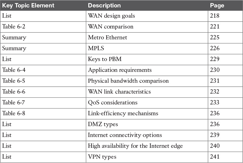
Review the most important topics in the chapter, noted with the Key Topic icon in the outer margin of the page. Table 6-9 lists a reference of these key topics and the page numbers on which each is found.
Complete Tables and Lists from Memory
Print a copy of Appendix D, “Memory Tables,” (found on the book website), or at least the section for this chapter, and complete the tables and lists from memory. Appendix E, “Memory Tables Answer Key,” also on the website, includes completed tables and lists to check your work.
Define Key Terms
Define the following key terms from this chapter, and check your answers in the glossary:
Q&A
The answers to these questions appear in Appendix A, “Answers to the ‘Do I Know This Already?’ Quizzes and Q&A Questions.” For more practice with exam format questions, use the exam engine on the CD.
1. When using PBM design methodology, what should a network designer do after identifying the customer requirements?
a. Design the network topology.
b. Design a test network.
c. Plan the implementation.
d. Characterize the existing network.
2. Which module is within the enterprise edge module?
a. Data center module
b. Campus core
c. Building distribution
d. Remote access VPN module
3. What WAN technology is most cost effective and suitable for the telecommuter?
a. MPLS
b. Dark fiber
c. ISDN
d. DSL
4. What two modules are found in the enterprise edge?
a. Campus core
b. Building access
c. Internet
d. DMZ
5. Which of the following statements best describes window size for good throughput?
a. A large window size reduces the number of acknowledgments.
b. A small window size reduces the number of acknowledgments.
c. A small window size provides better performance.
d. None of the above.
6. What is the default queuing mechanism for router interfaces below 2.0 Mbps?
a. Traffic shaping
b. WFQ
c. CBWFQ
d. LLQ
7. Which of the following best describe the PBM design methodology? (Select three.)
a. Analyze the network requirements.
b. Characterize the existing network.
c. Implement the network management.
d. Design the network topology.
8. Which of the following modules belongs in the enterprise edge?
a. Building distribution
b. Campus core
c. Network management
d. DMZ/e-commerce
9. Which network module connects to ISPs in the enterprise edge?
a. Building distribution
b. Campus core
c. WAN edge
d. Service provider edge
10. Which network module connects using the MPLS connectivity?
a. Remote access VPN
b. Campus core
c. Building access
d. WAN edge
11. Which network module connects using Frame Relay or ATM?
a. Remote access VPN
b. WAN edge
c. Building distribution
d. Server farm
12. During which part of the PBM design methodology does implementation planning occur?
a. Analyze the network requirements.
b. Design the topology.
c. Characterize the existing network.
d. None of the above.
13. What functional area provides connectivity between the central site and remote sites?
a. Access
b. Campus core
c. Building distribution
d. WAN edge
14. What WAN technology allows the enterprise to control framing?
a. Cable
b. Wireless
c. DWDM
d. Dark fiber
15. Which QoS method uses a strict PQ in addition to modular traffic classes?
a. CBWFQ
b. Policing
c. WFQ
d. LLQ
16. A T1 TDM circuit uses how many timeslots?
17. Which wireless implementation is designed to connect two wireless networks in different buildings?
a. Mobile wireless
b. GPRS
c. Bridge wireless
d. UMTS
18. What improves the utilization of optical-fiber strands?
19. On the ISP side of a cable provider, cable modems connect to what system?
20. If Frame Relay, ATM, and SONET technologies are used, what enterprise network module would they connect to?
a. WAN/MAN
b. VPN/remote access
c. Internet
d. DMZ/e-commerce
21. What protocol describes data-over-cable procedures that the equipment must support?
22. Into what WAN technology category does ISDN fit?
a. Cell switched
b. UTMS switched
c. Circuit switched
d. Packet switched
23. What do service providers use to define their service offerings at different levels?
a. SWAN
b. WAN tiers
c. WWAN
d. SLA
24. When is it appropriate to use various queuing solutions?
a. The WAN has frequent congestion problems.
b. The WAN occasionally becomes congested.
c. The WAN is consistently at 50 percent utilized.
d. The WAN is consistently at 40 percent utilized.