Chapter 10. Routing Protocol Characteristics, RIP, EIGRP, and IS-IS
This chapter covers the following subjects:
Routing Protocol Characteristics
Routing Protocol Metrics and Loop Prevention
This chapter covers the metrics used and other characteristics of routing protocols. Routing protocols can be categorized as distance-vector or link-state and as hierarchical or flat. The CCDA must understand how each routing protocol is categorized to select the one that meets the customer’s requirements. This chapter covers the routing protocols at a high level. The following chapters go into more detail about the operations and algorithms used in each routing protocol.
“Do I Know This Already?” Quiz
The “Do I Know This Already?” quiz helps you identify your strengths and deficiencies in this chapter’s topics.
The ten-question quiz, derived from the major sections in the “Foundation Topics” portion of the chapter, helps you determine how to spend your limited study time.
Table 10-1 outlines the major topics discussed in this chapter and the “Do I Know This Already?” quiz questions that correspond to those topics.

1. What is the default metric for any interface for the IS-IS routing protocol?
a. 5
b. 10
c. 70
d. 100
2. Which type of routing protocol would you use when connecting to an Internet service provider?
a. Classless routing protocol
b. Interior gateway protocol
c. Exterior gateway protocol
d. Classful routing protocol
3. Which routing protocol is distance-vector and classless?
a. RIPv2
b. EIGRP
c. OSPF
d. IS-IS
4. Which type of routing protocol sends periodic routing updates?
a. Static
b. Distance-vector
c. Link state
d. Hierarchical
5. Which distance-vector routing protocol is used for IPv6 networks?
a. OSPFv2
b. RIPng
c. OSPFv3
d. BGPv3
6. Which of the following is true regarding routing metrics?
a. If the metric is bandwidth, the path with the lowest bandwidth is selected.
b. If the metric is bandwidth, the path with the highest bandwidth is selected.
c. If the metric is bandwidth, the highest sum of the bandwidth is used to calculate the highest cost.
d. If the metric is cost, the path with the highest cost is selected.
7. Both OSPF and EIGRP are enabled on a router with default values. Both protocols have a route to a destination network in their databases. Which route is entered into the routing table?
a. The OSPF route.
b. The EIGRP route.
c. Both routes are entered with load balancing.
d. Neither route is entered; an error has occurred.
8. Which of the following are classless routing protocols?
a. RIPv1 and RIPv2
b. EIGRP and RIPv2
c. IS-IS and OSPF
d. Answers B and C
9. Which parameters are included in the computation of the EIGRP composite metric used by default?
a. Bandwidth and load
b. Bandwidth and delay
c. Bandwidth and reliability
d. Bandwidth and maximum transmission unit (MTU)
10. Which routing protocol implements the Diffusing Update Algorithm (DUAL)?
a. IS-IS
b. IGRP
c. EIGRP
d. OSPF
Foundation Topics
This chapter covers the high-level characteristics of routing protocols and their metrics. You should become familiar with the different categories of routing protocols and their characteristics for the exam. Understand how each metric is used and, based on the metric, which path is preferred. For example, you need to know that a path with the highest bandwidth is preferred over a path with a lower bandwidth. This chapter also covers distance-vector routing protocols: RIPv2, RIPng, and EIGRP.
Routing Protocol Characteristics
This section discusses the different types and characteristics of routing protocols.
Characteristics of routing-protocol design are

![]() Distance-vector, link-state, or hybrid: How routes are learned.
Distance-vector, link-state, or hybrid: How routes are learned.
![]() Interior or exterior: For use in private networks or the public Internet.
Interior or exterior: For use in private networks or the public Internet.
![]() Classless (classless interdomain routing [CIDR] support) or classful: CIDR enables aggregation of network advertisements (supernetting) between routers.
Classless (classless interdomain routing [CIDR] support) or classful: CIDR enables aggregation of network advertisements (supernetting) between routers.
![]() Fixed-length or variable-length subnet masks (VLSMs): Conserve addresses within a network.
Fixed-length or variable-length subnet masks (VLSMs): Conserve addresses within a network.
![]() Flat or hierarchical: Addresses scalability in large internetworks.
Flat or hierarchical: Addresses scalability in large internetworks.
![]() IPv4 or IPv6: Newer routing protocols are used for IPv6 networks.
IPv4 or IPv6: Newer routing protocols are used for IPv6 networks.
This section also covers the default administrative distance assigned to routes learned from each routing protocol or from static assignment. Routes are categorized as statically (manually) configured or dynamically learned from a routing protocol. The following sections cover all these characteristics.
Static Versus Dynamic Route Assignment
Static routes are manually configured on a router. When configured manually and not learned from a neighbor, they do not react to network outages. The one exception is when the static route specifies the outbound interface or the next hop is not resolved in the routing table. In this situation, if the interface goes down, the static route is removed from the routing table. Because static routes are unidirectional, they must be configured for each outgoing interface the router will use. The size of today’s networks makes it impossible to manually configure and maintain all the routes in all the routers in a timely manner. Human configuration can involve many mistakes. Dynamic routing protocols were created to address these shortcomings. They use algorithms to advertise, learn about, and react to changes in the network topology.
The main benefit of static routing is that a router generates no routing protocol overhead. Because no routing protocol is enabled, no bandwidth is consumed by route advertisements between network devices. Another benefit of static routing protocols is that they are easier to configure and troubleshoot than dynamic routing protocols. Static routing is recommended for hub-and-spoke topologies with low-speed remote connections and where only a single path to the network exists. A default static route is configured at each remote site because the hub is the only route used to reach all other sites. Static routes are also used at network boundaries (Internet or partners) where routing information is not exchanged. These static routes are then redistributed into the internal dynamic routing protocol used.
Figure 10-1 shows a hub-and-spoke WAN where static routes are defined in the remote WAN routers because no routing protocols are configured. This setup eliminates routing protocol traffic on the low-bandwidth WAN circuits.

Routing protocols dynamically determine the best route to a destination. When the network topology changes, the routing protocol adjusts the routes without administrative intervention. Routing protocols use a metric to determine the best path toward a destination network. Some use a single measured value such as hop count. Others compute a metric value using one or more parameters. Routing metrics are discussed later in this chapter. The following is a list of dynamic routing protocols:
![]() RIPv1
RIPv1
![]() RIPv2
RIPv2
![]() EIGRP
EIGRP
![]() OSPF
OSPF
![]() IS-IS
IS-IS
![]() RIPng
RIPng
![]() OSPFv3
OSPFv3
![]() EIGRP for IPv6
EIGRP for IPv6
![]() Border Gateway Protocol (BGP)
Border Gateway Protocol (BGP)
Interior Versus Exterior Routing Protocols
Routing protocols can be categorized as interior gateway protocols (IGPs) or exterior gateway protocols (EGPs). IGPs are meant for routing within an organization’s administrative domain (in other words, the organization’s internal network). EGPs are routing protocols used to communicate with exterior domains, where routing information is exchanged between administrative domains. Figure 10-2 shows where an internetwork uses IGPs and EGPs with multiple autonomous administrative domains. BGP exchanges routing information between the internal network and an ISP. IGPs appear in the internal private network.

One of the first EGPs was called exactly that: Exterior Gateway Protocol. Today, BGP is the de facto (and the only available) EGP.
Potential IGPs for an IPv4 network are
![]() RIPv2
RIPv2
![]() OSPFv2
OSPFv2
![]() IS-IS
IS-IS
![]() EIGRP
EIGRP
Potential IGPs for an IPv6 network are
![]() RIPng
RIPng
![]() OSPFv3
OSPFv3
![]() EIGRP for IPv6
EIGRP for IPv6
RIPv1 is no longer recommended because of its limitations. RIPv2 addresses many of the limitations of RIPv1 and is the most recent version of RIP. IGRP is an earlier version of EIGRP. RIPv1, RIPv2, and IGRP are no longer CCDA exam topics. Table 10-2 provides a quick high-level summary of which protocol should be selected.

Distance-Vector Routing Protocols
The first IGP routing protocols introduced were distance-vector routing protocols. They used the Bellman-Ford algorithm to build the routing tables. With distance-vector routing protocols, routes are advertised as vectors of distance and direction. The distance metric is usually router hop count. The direction is the next-hop router (IP address) toward which to forward the packet. For RIP, the maximum number of hops is 15, which can be a serious limitation, especially in large nonhierarchical internetworks.
Distance-vector algorithms call for each router to send its entire routing table to only its immediate neighbors. The table is sent periodically (30 seconds for RIP). In the period between advertisements, each router builds a new table to send to its neighbors at the end of the period. Because each router relies on its neighbors for route information, it is commonly said that distance-vector protocols “route by rumor.”
Having to wait half a minute for a new routing table with new routes is too long for today’s networks. This is why distance-vector routing protocols have slow convergence.
RIPv2 and RIPng can send triggered updates—full routing table updates sent before the update timer has expired. A router can receive a routing table with 500 routes with only one route change, which creates serious overhead on the network (another drawback). Furthermore, RFC 2091 updates RIP with triggered extensions to allow triggered updates with only route changes. Cisco routers support this on fixed point-to-point interfaces.
The following is a list of IP distance-vector routing protocols:
![]() RIPv1 and RIPv2
RIPv1 and RIPv2
![]() EIGRP (which could be considered a hybrid)
EIGRP (which could be considered a hybrid)
![]() RIPng
RIPng
EIGRP
EIGRP is a hybrid routing protocol. It is a distance-vector protocol that implements some link-state routing protocol characteristics. Although EIGRP uses distance-vector metrics, it sends partial updates and maintains neighbor state information just as link-state protocols do. EIGRP does not send periodic updates as other distance-vector routing protocols do. The important thing to consider for the test is that EIGRP could be presented as a hybrid protocol. EIGRP metrics and mechanisms are discussed later in this chapter.
Link-State Routing Protocols
Link-state routing protocols address some of the limitations of distance-vector protocols. When running a link-state routing protocol, routers originate information about themselves (IP addresses), their connected links (the number and types of links), and the state of those links (up or down). The information is flooded to all routers in the network as changes in the link state occur. Each router makes a copy of the information received and forwards it without change. Each router independently calculates the best paths to each destination network by using the Dijkstra shortest path algorithm, creating a shortest path tree with itself as the root, and maintains a map of the network.
After the initial exchange of information, link-state updates are not sent unless a change in the topology occurs. Routers do send small hello messages between neighbors to maintain neighbor relationships. If no updates have been sent, the link-state route database is refreshed after 30 minutes.
The following is a list of link-state routing protocols:
![]() OSPFv2
OSPFv2
![]() IS-IS
IS-IS
![]() OSPFv3
OSPFv3
OSPFv2 and OSPFv3 are covered in Chapter 11, “OSPF, BGP, Route Manipulation, and IP Multicast.”
Distance-Vector Routing Protocols Versus Link-State Protocols
When choosing a routing protocol, consider that distance-vector routing protocols use more network bandwidth than link-state protocols. Distance-vector protocols generate more bandwidth overhead because of the large periodic routing updates. Link-state routing protocols do not generate significant routing update overhead but do use more router CPU and memory resources than distance-vector protocols. This occurs because with link-state routing protocols (generally speaking), WAN bandwidth is a more expensive resource than router CPU and memory in modern devices.
Table 10-3 compares distance-vector to link-state routing protocols.

EIGRP is a distance-vector protocol with link-state characteristics (hybrid) that give it high scalability, fast convergence, less routing overhead, and relatively easy configuration. If “distance-vector” is not an answer to a question, then “hybrid” would be a valid option.
Hierarchical Versus Flat Routing Protocols
Some routing protocols require a network topology that must have a backbone network defined. This network contains some, or all, of the routers in the internetwork. When the internetwork is defined hierarchically, the backbone consists of only some devices. Backbone routers service and coordinate the routes and traffic to or from routers not in the local internetwork. The supported hierarchy is relatively shallow. Two levels of hierarchy are generally sufficient to provide scalability. Selected routers forward routes into the backbone. OSPF and IS-IS are hierarchical routing protocols. By default, EIGRP is a flat routing protocol, but it can be configured with manual summarization to support hierarchical designs.
Flat routing protocols do not allow a hierarchical network organization. They propagate all routing information throughout the network without dividing or summarizing large networks into smaller areas. Carefully designing network addressing to naturally support aggregation within routing-protocol advertisements can provide many of the benefits offered by hierarchical routing protocols. Every router is a peer of every other router in flat routing protocols; no router has a special role in the internetwork. EIGRP, RIPv1, and RIPv2 are flat routing protocols.
Classless Versus Classful Routing Protocols
Routing protocols can be classified based on their support of VLSM and CIDR. Classful routing protocols do not advertise subnet masks in their routing updates; therefore, the configured subnet mask for the IP network must be the same throughout the entire internetwork. Furthermore, the subnets must, for all practical purposes, be contiguous within the larger internetwork. For example, if you use a classful routing protocol for network 130.170.0.0, you must use the chosen mask (such as 255.255.255.0) on all router interfaces using the 130.170.0.0 network. You must configure serial links with only two hosts and LANs with tens or hundreds of devices with the same mask of 255.255.255.0. The big disadvantage of classful routing protocols is that the network designer cannot take advantage of address summarization across networks (CIDR) or allocation of smaller or larger subnets within an IP network (VLSM). For example, with a classful routing protocol that uses a default mask of /25 for the entire network, you cannot assign a /30 subnet to a serial point-to-point circuit. Classful routing protocols are
![]() RIPv1
RIPv1
![]() IGRP (this protocol is not a test topic)
IGRP (this protocol is not a test topic)
Classless routing protocols advertise the subnet mask with each route. You can configure subnetworks of a given IP network number with different subnet masks (VLSM). You can configure large LANs with a smaller subnet mask and configure serial links with a larger subnet mask, thereby conserving IP address space. Classless routing protocols also allow flexible route summarization and supernetting (CIDR). You create supernets by aggregating classful IP networks. For example, 200.100.100.0/23 is a supernet of 200.100.100.0/24 and 200.100.101.0/24. Classless routing protocols are
![]() RIPv2
RIPv2
![]() OSPF
OSPF
![]() EIGRP
EIGRP
![]() IS-IS
IS-IS
![]() RIPng
RIPng
![]() OSPFv3
OSPFv3
![]() EIGRP for IPv6
EIGRP for IPv6
![]() BGP
BGP
IPv4 Versus IPv6 Routing Protocols
With the increasing use of the IPv6 protocol, the CCDA must be prepared to design networks using IPv6 routing protocols. As IPv6 was defined, routing protocols needed to be updated to support the new IP address structure. None of the IPv4 routing protocols support IPv6 networks, and none of the IPv6 routing protocols are backward compatible with IPv4 networks. But both protocols can coexist on the same network, each with its own routing protocol. Devices with dual stacks recognize which protocol is being used by the IP Version field in the IP header.
RIPng is the IPv6-compatible RIP routing protocol. EIGRP for IPv6 is the new version of EIGRP that supports IPv6 networks. OSPFv3 was developed for IPv6 networks, and OSPFv2 remains for IPv4 networks. Internet drafts were written to provide IPv6 routing using IS-IS. Multiprotocol extensions for BGP provide IPv6 support for BGP. Table 10-4 summarizes IPv4 versus IPv6 routing protocols.

Administrative Distance
On Cisco routers running more than one routing protocol, it is possible for two different routing protocols to have a route to the same destination. Cisco routers assign each routing protocol an administrative distance. When multiple routes exist for a destination, the router selects the longest match. For example, to reach a destination of 170.20.10.1 OSPF has a route prefix of 170.20.10.0/24 and EIGRP has a route prefix of 170.20.0.0/16, the OSPF route is preferred because the /24 prefix is longer than the /16 prefix. It is more specific.
If two or more routing protocols offer the same route (with same prefix length) for inclusion in the routing table, the Cisco IOS router selects the route with the lowest administrative distance.
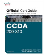
The administrative distance is a rating of the trustworthiness of a routing information source. Table 10-5 shows the default administrative distance for configured (static) or learned routes. In the table, you can see that static routes are trusted over dynamically learned routes. Within IGP routing protocols, EIGRP internal routes are trusted over OSPF, IS-IS, and RIP routes.
The administrative distance establishes the precedence used among routing algorithms. Suppose a router has an EIGRP route to network 172.20.10.0/24 with the best path out Ethernet 0 and an OSPF route for the same network out Ethernet 1. Because EIGRP has an administrative distance of 90 and OSPF has an administrative distance of 110, the router enters the EIGRP route in the routing table and sends packets with destinations of 172.20.10.0/24 out Ethernet 0.
Static routes have a default administrative distance of 1. There is one exception. If the static route points to a connected interface, it inherits the administrative distance of connected interfaces, which is 0. You can configure static routes with a different distance by appending the distance value to the end of the command.
Table 10-6 provides a summary of routing protocol characteristics.

Routing Protocol Metrics and Loop Prevention
Routing protocols use a metric to determine best routes to a destination. Some routing protocols use a combination of metrics to build a composite metric for best path selection. This section describes metrics and also covers routing loop-prevention techniques. You must understand each metric for the CCDA exam.
Some routing metric parameters are
![]() Hop count
Hop count
![]() Bandwidth
Bandwidth
![]() Cost
Cost
![]() Load
Load
![]() Delay
Delay
![]() Reliability
Reliability
![]() Maximum transmission unit (MTU)
Maximum transmission unit (MTU)
Hop Count
The hop count parameter counts the number of links between routers the packet must traverse to reach a destination. The RIP routing protocol uses hop count as the metric for route selection. If all links were the same bandwidth, this metric would work well. The problem with routing protocols that use only this metric is that the shortest hop count is not always the most appropriate path. For example, between two paths to a destination network—one with two 56Kbps links and another with four T1 links—the router chooses the first path because of the lower number of hops (see Figure 10-3). However, this is not necessarily the best path. You would prefer to transfer a 20MB file via the T1 links rather than the 56Kbps links.

Bandwidth
The bandwidth parameter uses the interface bandwidth to determine a best path to a destination network. When bandwidth is the metric, the router prefers the path with the highest bandwidth to a destination. For example, a Fast Ethernet (100 Mbps) is preferred over a DS-3 (45 Mbps). As shown in Figure 10-3, a router using bandwidth to determine a path would select Path 2 because of the larger bandwidth (1.5 Mbps over 56 Kbps).
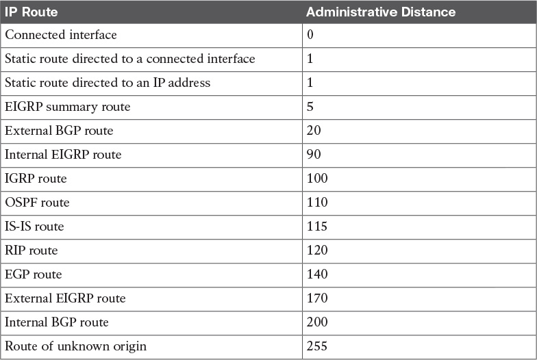
If a routing protocol uses only bandwidth as the metric and the path has several different speeds, the protocol can use the lowest speed in the path to determine the bandwidth for the path. EIGRP and IGRP use the minimum path bandwidth, inverted and scaled, as one part of the metric calculation. In Figure 10-4, Path 1 has two segments, with 256 Kbps and 512 Kbps of bandwidth. Because the smaller speed is 256 Kbps, this speed is used as Path 1’s bandwidth. The smallest bandwidth in Path 2 is 384 Kbps. When the router has to choose between Path 1 and Path 2, it selects Path 2 because 384 Kbps is larger than 256 Kbps.
Cost
Cost is the name of the metric used by OSPF and IS-IS. In OSPF on a Cisco router, a link’s default cost is derived from the interface’s bandwidth. Cisco’s implementation of IS-IS assigns a default cost of 10 to all interfaces.
The formula to calculate cost in OSPF is
108/BW
where BW is the interface’s default or configured bandwidth.
For 10Mbps Ethernet, cost is calculated as follows:
BW = 10 Mbps = 10 * 106 = 10,000,000 = 107
cost (Ethernet) = 108 / 107 = 10
The sum of all the costs to reach a destination is the metric for that route. The lowest cost is the preferred path.
Figure 10-5 shows an example of how the path costs are calculated. The path cost is the sum of all costs in the path. The cost for Path 1 is 350 + 180 = 530. The cost for Path 2 is 15 + 50 + 100 + 50 = 215.

Because the cost of Path 2 is less than that of Path 1, Path 2 is selected as the best route to the destination.
Load
The load parameter refers to the degree to which the interface link is busy. The router keeps track of interface utilization; routing protocols can use this metric when calculating the best route. Load is one of the five parameters included in the definition of the EIGRP metric. By default, it is not used to calculate the composite metric. If you have 512Kbps and 256Kbps links to reach a destination, but the 512Kbps circuit is 99 percent busy and the 256Kbps circuit is only 5 percent busy, the 256Kbps link is the preferred path. On Cisco routers, the percentage of load is shown as a fraction over 255. Utilization at 100 percent is shown as 255/255, and utilization at 0 percent is shown as 0/255. Example 10-1 shows the load of a serial interface at 5/255 (1.9 percent).
router3>show interface serial 1
Serial1 is up, line protocol is up
Hardware is PQUICC Serial
Internet address is 10.100.1.1/24
MTU 1500 bytes, BW 1544 Kbit, DLY 20000 usec, rely 255/255, load 5/255
Delay
The delay parameter refers to how long it takes to move a packet to the destination. Delay depends on many factors, such as link bandwidth, utilization, port queues, and physical distance traveled. Total delay is one of the five parameters included in the definition of the EIGRP composite metric. By default, it is used to calculate the composite metric. You can configure an interface’s delay with the delay tens-of-microseconds command, where tens-of-microseconds specifies the delay in tens of microseconds for an interface or network segment. The interface delay can be checked with the show interface command. As shown in Example 10-2, the interface’s delay is 20,000 microseconds.
router3>show interface serial 1
Serial1 is up, line protocol is up
Hardware is PQUICC Serial
Internet address is 10.100.1.1/24
MTU 1500 bytes, BW 1544 Kbit, DLY 20000 usec, rely 255/255, load 1/255
Reliability
The reliability parameter is the dependability of a network link. Some WAN links tend to go up and down throughout the day. These links get a small reliability rating. Reliability is measured by factors such as a link’s expected received keepalives and the number of packet drops and interface resets. If the ratio is high, the line is reliable. The best rating is 255/255, which is 100 percent reliability. Reliability is one of the five parameters included in the definition of the EIGRP metric. By default, it is not used to calculate the composite metric. As shown in Example 10-3, you can verify an interface’s reliability using the show interface command.
Example 10-3 Interface Reliability
router4#show interface serial 0
Serial0 is up, line protocol is up
Hardware is PQUICC Serial
MTU 1500 bytes, BW 1544 Kbit, DLY 20000 usec, rely 255/255, load 1/255
Maximum Transmission Unit
The MTU parameter is simply the maximum size of bytes a unit can have on an interface. If the outgoing packet is larger than the MTU, the IP protocol might need to fragment it. If a packet larger than the MTU has the Do Not Fragment flag set, the packet is dropped. As shown in Example 10-4, you can verify an interface’s MTU using the show interface command.
router4#show interface serial 0
Serial0 is up, line protocol is up
Hardware is PQUICC Serial
MTU 1500 bytes, BW 1544 Kbit, DLY 20000 usec, rely 255/255, load 1/255
Routing Loop-Prevention Schemes
Some routing protocols employ schemes to prevent the creation of routing loops in the network. These schemes are
![]() Split horizon
Split horizon
![]() Poison reverse
Poison reverse
![]() Counting to infinity
Counting to infinity
Split Horizon
Split horizon is a technique used by distance-vector routing protocols to prevent routing loops. Routes that are learned from a neighboring router are not sent back to that neighboring router, thus suppressing the route. If the neighbor is already closer to the destination, it already has a better path.
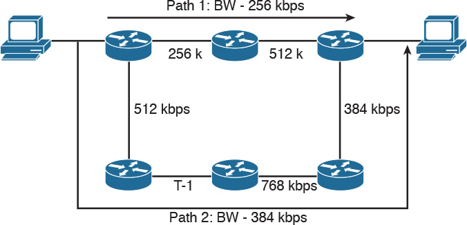
In Figure 10-6, Routers 1, 2, and 3 learn about Networks A, B, C, and D. Router 2 learns about Network A from Router 1 and also has Networks B and C in its routing table. Router 3 advertises Network D to Router 2. Now, Router 2 knows about all networks. Router 2 sends its routing table to Router 3 without the route for Network D because it learned that route from Router 3.
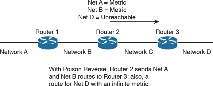
Poison Reverse
Poison reverse is a route update sent out an interface with an infinite metric for routes learned (received) from the same interface. Poison reverse simply indicates that the learned route is unreachable. It is more reliable than split horizon alone. Examine Figure 10-7. Instead of suppressing the route for Network D, Router 2 sends that route in the routing table marked as unreachable. In RIP, the poison-reverse route is marked with a metric of 16 (infinite) to prevent that path from being used.
Counting to Infinity
Some routing protocols keep track of router hops as the packet travels through the network. In large networks where a routing loop might be present because of a network outage, routers might forward a packet without it reaching its destination.
Counting to infinity is a loop-prevention technique in which the router discards a packet when it reaches a maximum limit. It assumes that the network diameter is smaller than the maximum allowed hops. RIP has a maximum of 16 hops, and EIGRP has a maximum of 100 hops by default. These values are considered infinity.
Triggered Updates
Another loop-prevention and fast-convergence technique used by routing protocols is triggered updates. When a router interface changes state (up or down), the router is required to send an update message, even if it is not time for the periodic update message. Immediate notification about a network outage is key to maintaining valid routing entries within all routers in the network by allowing faster convergence. Some distance-vector protocols, including RIP, specify a small time delay to avoid having triggered updates generate excessive network traffic. The time delay is variable for each router.
Summarization
Another characteristic of routing protocols is the ability to summarize routes. Protocols that support VLSMs can perform summarization outside of IP class boundaries. By summarizing, the routing protocol can reduce the size of the routing table, and fewer routing updates on the network occur.
RIPv2 and RIPng
This section covers RIPv2 and RIPng. Although Cisco has removed RIP from the exam topics for the test, this section is included for reference. It is possible that you will see questions on RIP or see RIPv2 and RIPng mentioned as possible answers to a test question.
RIPv2 is used for IPv4 networks, and RIPng was created to support IPv6 networks. RIPv2 was first described in RFC 1388 and RFC 1723 (1994); the current RFC is 2453, written in November 1998. Although current environments use advanced routing protocols such as OSPF and EIGRP, some networks still use RIP. The need to use VLSMs and other requirements prompted the definition of RIPv2. RIPv1 was the first version of RIP, which did not support VLSMs. RIPv1 is not a CCDA topic.
RIPv2 improves on RIPv1 with the ability to use VLSM, support for route authentication, and multicasting of route updates. RIPv2 supports CIDR. It still sends updates every 30 seconds and retains the 15-hop limit; it also uses triggered updates. RIPv2 still uses UDP port 520; the RIP process is responsible for checking the version number. It retains the loop-prevention strategies of split-horizon, poison reverse, and counting to infinity. On Cisco routers, RIPv2 has the same administrative distance as RIPv1, which is 120. Finally, RIPv2 uses the IP address 224.0.0.9 when multicasting route updates to other RIP routers. As in RIPv1, RIPv2 by default summarizes IP networks at network boundaries. You can disable autosummarization if required.
You can use RIPv2 in small networks where VLSM is required. It also works at the edge of larger networks.
Authentication
Authentication can prevent communication with any RIP routers that are not intended to be part of the network, such as UNIX stations running routed. Only RIP updates with the authentication password are accepted. RFC 1723 defines simple plain-text authentication for RIPv2.
MD5 Authentication
In addition to plaintext passwords, the Cisco implementation provides the ability to use message digest 5 (MD5) authentication, which is defined in RFC 1321. MD5 is a hashing algorithm that takes a variable-length string of text and produces a fixed-length 128-bit output. One significant advantage to hashing plaintext is that the original message cannot be reconstituted even with knowledge of the hash algorithm. This provides greater security than using plaintext authentication.
RIPv2 Routing Database
RIPv2 maintains a routing table database, as in Version 1. The difference is that it also keeps the subnet mask information. The following list repeats the table information of RIPv1:
![]() IP Address: The IP address of the destination host or network, with subnet mask
IP Address: The IP address of the destination host or network, with subnet mask
![]() Gateway: The first gateway along the path to the destination
Gateway: The first gateway along the path to the destination
![]() Interface: The physical network that must be used to reach the destination
Interface: The physical network that must be used to reach the destination
![]() Metric: A number indicating the number of hops to the destination
Metric: A number indicating the number of hops to the destination
![]() Timer: The amount of time since the route entry was last updated
Timer: The amount of time since the route entry was last updated
RIPv2 Message Format
The RIPv2 message format takes advantage of the unused fields in the RIPv1 message format by adding subnet masks and other information. Figure 10-8 shows the RIPv2 message format.

The following list describes each field:
![]() Command: Indicates whether the packet is a request or response message. The request message asks that a router send all or a part of its routing table. Response messages contain route entries. The router sends the response periodically or as a reply to a request.
Command: Indicates whether the packet is a request or response message. The request message asks that a router send all or a part of its routing table. Response messages contain route entries. The router sends the response periodically or as a reply to a request.
![]() Version: Specifies the RIP version used. It is set to 2 for RIPv2 and to 1 for RIPv1.
Version: Specifies the RIP version used. It is set to 2 for RIPv2 and to 1 for RIPv1.
![]() AFI: Specifies the address family used. RIP is designed to carry routing information for several different protocols. Each entry has an AFI to indicate the type of address specified. The AFI for IP is 2. The AFI is set to 0xFFF for the first entry to indicate that the remainder of the entry contains authentication information.
AFI: Specifies the address family used. RIP is designed to carry routing information for several different protocols. Each entry has an AFI to indicate the type of address specified. The AFI for IP is 2. The AFI is set to 0xFFF for the first entry to indicate that the remainder of the entry contains authentication information.
![]() Route tag: Provides a method for distinguishing between internal routes (learned by RIP) and external routes (learned from other protocols). You can add this optional attribute during the redistribution of routing protocols.
Route tag: Provides a method for distinguishing between internal routes (learned by RIP) and external routes (learned from other protocols). You can add this optional attribute during the redistribution of routing protocols.
![]() IP Address: Specifies the IP address (network) of the destination.
IP Address: Specifies the IP address (network) of the destination.
![]() Subnet Mask: Contains the subnet mask for the destination. If this field is 0, no subnet mask has been specified for the entry.
Subnet Mask: Contains the subnet mask for the destination. If this field is 0, no subnet mask has been specified for the entry.
![]() Next Hop: Indicates the IP address of the next hop where packets are sent to reach the destination.
Next Hop: Indicates the IP address of the next hop where packets are sent to reach the destination.
![]() Metric: Indicates how many router hops to reach the destination. The metric is between 1 and 15 for a valid route or 16 for an unreachable or infinite route.
Metric: Indicates how many router hops to reach the destination. The metric is between 1 and 15 for a valid route or 16 for an unreachable or infinite route.
Again, as in RIPv1, the router permits up to 25 occurrences of the last five 32-bit words (20 bytes), for up to 25 routes per RIP message. If the AFI specifies an authenticated message, the router can specify only 24 routing table entries. The updates are sent to the multicast address of 224.0.0.9.
RIPv2 Timers
RIPv2 timers are the same as in RIPv1. They send periodic updates every 30 seconds. The default invalid timer is 180 seconds, the hold-down timer is 180 seconds, and the flush timer is 240 seconds. You can write this list as 30/180/180/240, representing the U/I/H/F timers.
RIPv2 Design
Things to remember in designing a network with RIPv2 include that it supports VLSM within networks and allows for the summarization of routes in a hierarchical network. RIPv2 is still limited to 16 hops; therefore, the network diameter cannot exceed this limit. RIPv2 multicasts its routing table every 30 seconds to the multicast IP address 224.0.0.9. RIPv2 is usually limited to accessing networks where it can interoperate with servers running routed or with non-Cisco routers. RIPv2 also appears at the edge of larger internetworks. RIPv2 further provides for route authentication.
As shown in Figure 10-9, when you use RIPv2, all segments can have different subnet masks.

RIPv2 Summary
The characteristics of RIPv2 follow:
![]() Distance-vector protocol.
Distance-vector protocol.
![]() Uses UDP port 520.
Uses UDP port 520.
![]() Classless protocol (support for CIDR).
Classless protocol (support for CIDR).
![]() Supports VLSMs.
Supports VLSMs.
![]() Metric is router hop count.
Metric is router hop count.
![]() Low scalability: maximum hop count is 15; infinite (unreachable) routes have a metric of 16.
Low scalability: maximum hop count is 15; infinite (unreachable) routes have a metric of 16.
![]() Periodic route updates are sent every 30 seconds to multicast address 224.0.0.9.
Periodic route updates are sent every 30 seconds to multicast address 224.0.0.9.
![]() There can be 25 routes per RIP message (24 if you use authentication).
There can be 25 routes per RIP message (24 if you use authentication).
![]() Supports authentication.
Supports authentication.
![]() Implements split horizon with poison reverse.
Implements split horizon with poison reverse.
![]() Implements triggered updates.
Implements triggered updates.
![]() Subnet mask is included in the route entry.
Subnet mask is included in the route entry.
![]() Administrative distance for RIPv2 is 120.
Administrative distance for RIPv2 is 120.
![]() Not scalable. Used in small, flat networks or at the edge of larger networks.
Not scalable. Used in small, flat networks or at the edge of larger networks.
RIPng
RIPng (RIP next generation) is the version of RIP that can be used in IPv6 networks. It is described in RFC 2080. Most of the RIP mechanisms from RIPv2 remain the same. RIPng still has a 15-hop limit, counting to infinity, and split horizon with poison reverse. A hop count of 16 still indicates an unreachable route.
Instead of using UDP port 520, as in RIPv2, RIPng uses UDP port 521. RIPng supports IPv6 addresses and prefixes. RIPng uses multicast group FF02::9 for RIPng updates to all RIPng routers.
RIPng Timers
RIPng timers are similar to RIPv2. Periodic updates are sent every 30 seconds. The default invalid timeout for routes to expire is 180 seconds, the default hold-down timer is 180 seconds, and the default garbage-collection timer is 120 seconds.
Authentication
RIPng does not implement authentication methods in its protocol as RIPv2 does. RIPng relies on built-in IPv6 authentication functions.
RIPng Message Format
Figure 10-10 shows the RIPng routing message. Each route table entry (RTE) consists of the IPv6 prefix, route tag, prefix length, and metric.

The following list describes each field:
![]() Command: Indicates whether the packet is a request or response message. This field is set to 1 for a request and to 2 for a response.
Command: Indicates whether the packet is a request or response message. This field is set to 1 for a request and to 2 for a response.
![]() Version: Set to 1, the first version of RIPng.
Version: Set to 1, the first version of RIPng.
![]() IPv6 prefix: The destination 128-bit IPv6 prefix.
IPv6 prefix: The destination 128-bit IPv6 prefix.
![]() Route Tag: As with RIPv2, this is a method that distinguishes internal routes (learned by RIP) from external routes (learned by external protocols). Tagged during redistribution.
Route Tag: As with RIPv2, this is a method that distinguishes internal routes (learned by RIP) from external routes (learned by external protocols). Tagged during redistribution.
![]() Prefix Length: Indicates the significant part of the prefix.
Prefix Length: Indicates the significant part of the prefix.
![]() Metric: This 8-bit field contains the router hop metric.
Metric: This 8-bit field contains the router hop metric.
RIPv2 has a Next Hop field for each of its route entries. An RTE with a metric of 0xFF indicates the next-hop address to reduce the number of route entries in RIPng. It groups all RTEs after it to summarize all destinations to that particular next-hop address. Figure 10-11 shows the format of the special RTE indicating the next-hop entry.

RIPng Design
RIPng has low scalability. As with RIPv2, it is limited to 15 hops; therefore, the network diameter cannot exceed this limit. RIPng also broadcasts its routing table every 30 seconds, which causes network overhead. RIPng can be used only in small networks.
RIPng Summary
The characteristics of RIPng are as follows:
![]() Distance-vector protocol for IPv6 networks only.
Distance-vector protocol for IPv6 networks only.
![]() Uses UDP port 521.
Uses UDP port 521.
![]() Metric is router hop count.
Metric is router hop count.
![]() Maximum hop count is 15; infinite (unreachable) routes have a metric of 16.
Maximum hop count is 15; infinite (unreachable) routes have a metric of 16.
![]() Periodic route updates are sent every 30 seconds to multicast address FF02::9.
Periodic route updates are sent every 30 seconds to multicast address FF02::9.
![]() Uses IPv6 functions for authentication.
Uses IPv6 functions for authentication.
![]() Implements split horizon with poison reverse.
Implements split horizon with poison reverse.
![]() Implements triggered updates.
Implements triggered updates.
![]() Prefix length included in route entry.
Prefix length included in route entry.
![]() Administrative distance for RIPng is 120.
Administrative distance for RIPng is 120.
![]() Not scalable. Used in small networks.
Not scalable. Used in small networks.
EIGRP
Cisco Systems released EIGRP in the early 1990s as an evolution of IGRP toward a more scalable routing protocol for large internetworks. EIGRP is a classless protocol that permits the use of VLSMs and that supports CIDR for the scalable allocation of IP addresses. EIGRP does not send routing updates periodically, as does IGRP. EIGRP allows for authentication with MD5. EIGRP autosummarizes networks at network borders and can load-share over unequal-cost paths. Packets using EIGRP use IP 88. Only Cisco routers use EIGRP. However, Cisco has released EIGRP as an IETF draft, so it might be possible that other vendors implement EIGRP in their network devices.
EIGRP is an advanced distance-vector protocol that implements some characteristics similar to those of link-state protocols. Some Cisco documentation refers to EIGRP as a hybrid protocol. EIGRP advertises its routing table to its neighbors as distance-vector protocols do, but it uses hellos and forms neighbor relationships as link-state protocols do. EIGRP sends partial updates when a metric or the topology changes on the network. It does not send full routing-table updates in periodic fashion as do distance-vector protocols. EIGRP uses Diffusing Update Algorithm (DUAL) to determine loop-free paths to destinations. This section discusses DUAL.
By default, EIGRP load-balances traffic if several paths have an equal cost to the destination. EIGRP performs unequal-cost load sharing if you configure it with the variance n command. EIGRP includes routes that are equal to or less than n times the minimum metric route to a destination. As in RIP and IGRP, EIGRP also summarizes IP networks at network boundaries.
EIGRP internal routes have an administrative distance of 90. EIGRP summary routes have an administrative distance of 5, and EIGRP external routes (from redistribution) have an administrative distance of 170.
EIGRP Components
EIGRP has four components that characterize it:
![]() Protocol-dependent modules
Protocol-dependent modules
![]() Neighbor discovery and recovery
Neighbor discovery and recovery
![]() Reliable Transport Protocol (RTP)
Reliable Transport Protocol (RTP)
![]() Diffusing Update Algorithm (DUAL)
Diffusing Update Algorithm (DUAL)
You should know the role of the EIGRP components, which are described in the following sections.
Protocol-Dependent Modules
EIGRP uses different modules that independently support IP, Internetwork Packet Exchange (IPX), and AppleTalk routing protocols. These modules are the logical interface between DUAL and routing protocols such as IPX RIP, and AppleTalk Routing Table Maintenance Protocol (RTMP). The EIGRP module sends and receives packets but passes received information to DUAL, which makes routing decisions.
When configured to support IPX, EIGRP communicates with the IPX RIP and forwards the route information to DUAL to select the best paths. AppleTalk EIGRP automatically redistributes routes with AppleTalk RTMP to support AppleTalk networks. IPX and AppleTalk are not CCDA objectives and are therefore not covered in this book.
Neighbor Discovery and Recovery
EIGRP discovers and maintains information about its neighbors. It multicasts hello packets (224.0.0.10) every 5 seconds on most interfaces. The router builds a table with EIGRP neighbor information. The holdtime to maintain a neighbor is three times the hello time: 15 seconds. If the router does not receive a hello in 15 seconds, it removes the neighbor from the table. EIGRP multicasts hellos every 60 seconds on multipoint WAN interfaces (X.25, Frame Relay, ATM) with speeds less than a T-1 (1.544 Mbps), inclusive. The neighbor holdtime is 180 seconds on these types of interfaces. To summarize, hello/holdtime timers are 5/15 seconds for high-speed links and 60/180 seconds for low-speed links.
Example 10-5 shows an EIGRP neighbor database. The table lists the neighbor’s IP address, the interface to reach it, the neighbor holdtime timer, and the uptime.
Example 10-5 EIGRP Neighbor Database
Router# show ip eigrp neighbor
IP-EIGRP neighbors for process 100
H Address Interface Hold Uptime SRTT RTO Q Seq Type
c (sec) (ms) Cnt Num
1 172.17.1.1 Se0 11 00:11:27 16 200 0 2
0 172.17.2.1 Et0 12 00:16:11 22 200 0 3
RTP
EIGRP uses RTP to manage EIGRP packets. RTP ensures the reliable delivery of route updates and uses sequence numbers to ensure ordered delivery. It sends update packets using multicast address 224.0.0.10. It acknowledges updates using unicast hello packets with no data.
DUAL
EIGRP implements DUAL to select paths and guarantee freedom from routing loops. J.J. Garcia Luna-Aceves developed DUAL. It is mathematically proven to result in a loop-free topology, providing no need for periodic updates or route holddown mechanisms that make convergence slower.
DUAL selects a best path and a second-best path to reach a destination. The best path selected by DUAL is the successor, and the second-best path (if available) is the feasible successor. The feasible distance is the lowest calculated metric of a path to reach the destination. The topology table in Example 10-6 shows the feasible distance. The example also shows two paths (Ethernet 0 and Ethernet 1) to reach 172.16.4.0/30. Because the paths have different metrics, DUAL chooses only one successor.
Example 10-6 Feasible Distance as Shown in the EIGRP Topology Table
Router8# show ip eigrp topology
IP-EIGRP Topology Table for AS(100)/ID(172.16.3.1)
Codes: P - Passive, A - Active, U - Update, Q - Query, R - Reply,
r - reply Status, s - sia Status
P 172.16.4.0/30, 1 successors, FD is 2195456
via 172.16.1.1 (2195456/2169856), Ethernet0
via 172.16.5.1 (2376193/2348271), Ethernet1
P 172.16.1.0/24, 1 successors, FD is 281600
via Connected, Ethernet0
The route entries in Example 10-6 are marked with a P for the passive state. A destination is in passive state when the router is not performing any recomputations for the entry. If the successor goes down and the route entry has feasible successors, the router does not need to perform any recomputations and does not go into active state.
DUAL places the route entry for a destination into active state if the successor goes down and there are no feasible successors. EIGRP routers send query packets to neighboring routers to find a feasible successor to the destination. A neighboring router can send a reply packet that indicates it has a feasible successor or a query packet. The query packet indicates that the neighboring router does not have a feasible successor and will participate in the recomputation. A route does not return to passive state until it has received a reply packet from each neighboring router. If the router does not receive all the replies before the “active-time” timer expires, DUAL declares the route as stuck in active (SIA). The default active timer is 3 minutes.
EIGRP Timers
EIGRP sends updates only when necessary and sends them only to neighboring routers. There is no periodic update timer.
EIGRP uses hello packets to learn of neighboring routers. On high-speed networks, the default hello packet interval is 5 seconds. On multipoint networks with link speeds of T1 and slower, hello packets are unicast every 60 seconds.
The holdtime to maintain a neighbor adjacency is three times the hello time: 15 seconds. If a router does not receive a hello within the holdtime, it removes the neighbor from the table. Hellos are multicast every 60 seconds on multipoint WAN interfaces (X.25, Frame Relay, ATM) with speeds less than 1.544 Mbps, inclusive. The neighbor holdtime is 180 seconds on these types of interfaces. To summarize, hello/holdtime timers are 5/15 seconds for high-speed links and 60/180 seconds for multipoint WAN links less than 1.544 Mbps, inclusive.
Note
EIGRP does not send updates using a broadcast address; instead, it sends them to the multicast address 224.0.0.10 (all EIGRP routers). It also can send any updates using unicast packets if the neighbor command is used.
EIGRP Metrics
EIGRP uses the same composite metric as IGRP, but the bandwidth (BW) term is multiplied by 256 for finer granularity. The composite metric is based on bandwidth, delay, load, and reliability. MTU is not an attribute for calculating the composite metric.
EIGRP calculates the composite metric with the following formula:
EIGRPmetric = {k1 * BW + [(k2 * BW)/(256 – load)] + k3 * delay} * {k5/(reliability + k4)}
In this formula, BW is the lowest interface bandwidth in the path, and delay is the sum of all outbound interface delays in the path. The router dynamically measures reliability and load. It expresses 100 percent reliability as 255/255. It expresses load as a fraction of 255. An interface with no load is represented as 1/255.
Bandwidth is the inverse minimum bandwidth (in Kbps) of the path in bits per second scaled by a factor of 256 * 107. The formula for bandwidth is
(256 * 107)/BWmin
The delay is the sum of the outgoing interface delays (in tens of microseconds) to the destination. A delay of all 1s (that is, a delay of hexadecimal FFFFFFFF) indicates that the network is unreachable. The formula for delay is
[sum of delays] * 256
Reliability is a value between 1 and 255. Cisco IOS routers display reliability as a fraction of 255. That is, 255/255 is 100 percent reliability, or a perfectly stable link; a value of 229/255 represents a 90 percent reliable link.
Load is a value between 1 and 255. A load of 255/255 indicates a completely saturated link. A load of 127/255 represents a 50 percent saturated link.
By default, k1 = k3 = 1 and k2 = k4 = k5 = 0. EIGRP’s default composite metric, adjusted for scaling factors, is
EIGRPmetric = 256 * { [107/BWmin] + [sum_of_delays] }
BWmin is in Kbps, and sum_of_delays is in 10s of microseconds. The bandwidth and delay for an Ethernet interface are 10 Mbps and 1 ms, respectively.
The calculated EIGRP BW metric is
256 * 107/BW = 256 * 107/10,000
= 256 * 10,000
= 256,000
The calculated EIGRP delay metric is
256 * sum of delay = 256 * 1 ms
= 256 * 100 * 1 microseconds
= 25,600 (in 10s of microseconds)
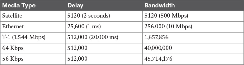
Table 10-7 shows some default values for bandwidth and delay.
The metric weights subcommand is used to change EIGRP metric computation. You can change the k values in the EIGRP composite metric formula to select which EIGRP metrics to use. The command to change the k values is the metric weights tos k1 k2 k3 k4 k5 subcommand under router eigrp n. The tos value is always 0. You set the other arguments to 1 or 0 to alter the composite metric. For example, if you want the EIGRP composite metric to use all the parameters, the command is as follows:
router eigrp n
metric weights 0 1 1 1 1 1
EIGRP Packet Types
EIGRP uses five packet types:
![]() Hello: EIGRP uses hello packets in the discovery of neighbors. They are multicast to 224.0.0.10. By default, EIGRP sends hello packets every 5 seconds (60 seconds on WAN links with 1.544 Mbps speeds or less).
Hello: EIGRP uses hello packets in the discovery of neighbors. They are multicast to 224.0.0.10. By default, EIGRP sends hello packets every 5 seconds (60 seconds on WAN links with 1.544 Mbps speeds or less).
![]() Acknowledgment: An acknowledgment packet acknowledges the receipt of an update packet. It is a hello packet with no data. EIGRP sends acknowledgment packets to the unicast address of the sender of the update packet.
Acknowledgment: An acknowledgment packet acknowledges the receipt of an update packet. It is a hello packet with no data. EIGRP sends acknowledgment packets to the unicast address of the sender of the update packet.
![]() Update: Update packets contain routing information for destinations. EIGRP unicasts update packets to newly discovered neighbors; otherwise, it multicasts update packets to 224.0.0.10 when a link or metric changes. Update packets are acknowledged to ensure reliable transmission.
Update: Update packets contain routing information for destinations. EIGRP unicasts update packets to newly discovered neighbors; otherwise, it multicasts update packets to 224.0.0.10 when a link or metric changes. Update packets are acknowledged to ensure reliable transmission.
![]() Query: EIGRP sends query packets to find feasible successors to a destination. Query packets are always multicast unless they are sent as a response; then they are unicast back to the originator.
Query: EIGRP sends query packets to find feasible successors to a destination. Query packets are always multicast unless they are sent as a response; then they are unicast back to the originator.
![]() Reply: EIGRP sends reply packets to respond to query packets. Reply packets provide a feasible successor to the sender of the query. Reply packets are unicast to the sender of the query packet.
Reply: EIGRP sends reply packets to respond to query packets. Reply packets provide a feasible successor to the sender of the query. Reply packets are unicast to the sender of the query packet.
EIGRP Design
When designing a network with EIGRP, remember that it supports VLSMs and network summarization. EIGRP allows for the summarization of routes in a hierarchical network. EIGRP is not limited to 16 hops as RIP is; therefore, the network diameter can exceed this limit. In fact, the EIGRP diameter can be 225 hops. The default diameter is 100. EIGRP can be used in the site-to-site WAN and IPsec virtual private networks (VPNs). In the enterprise campus, EIGRP can be used in data centers, server distribution, building distribution, and the network core.
EIGRP does not broadcast its routing table periodically, so there is no large network overhead. You can use EIGRP for large networks; it is a potential routing protocol for the core of a large network. EIGRP further provides for route authentication.
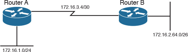
As shown in Figure 10-12, when you use EIGRP, all segments can have different subnet masks.
EIGRP is suited for almost all enterprise environments, including LANs and WANs, and is simple to design. The only caveat is that it is a Cisco proprietary routing protocol that cannot be used with routers from other vendors. The use of EIGRP is preferred over RIP in all environments.
EIGRP Stub Routers
EIGRP allows for the configuration of stub routers for remote branches. It is used to reduce EIGRP query traffic between hub routers and remote branch routers that are connected over WAN links. Figure 10-13 shows an example of an EIGRP stub router operation. If the LAN network 10.10.10.0/24 goes down, the Hub1 router sends query packets everywhere; however, there is no need to send query packets to stub branches because there are no alternate routes there. Once you configure the branch routers as EIGRP stub routers, the query is sent only to the Hub2 router.

There are different options when configuring the EIGRP stub routers:
![]() Receive-only: The stub router will not advertise any network.
Receive-only: The stub router will not advertise any network.
![]() Connected: Allows the stub router to advertise directly connected networks.
Connected: Allows the stub router to advertise directly connected networks.
![]() Static: Allows the stub router to advertise static routes.
Static: Allows the stub router to advertise static routes.
![]() Summary: Allows the stub router to advertise summary routes.
Summary: Allows the stub router to advertise summary routes.
![]() Redistribute: Allows the stub router to advertise redistributed routes.
Redistribute: Allows the stub router to advertise redistributed routes.
EIGRP Variance Command
EIGRP allows unequal-cost routing with the use of the variance # command. If you have an active route with a metric of 10 and have feasible successors of 15, 25, and 55, you can adjust the variance number to make those routes active. If you use variance 2, then the active metric of 10 gets multiplied by 2, which equals 20. Any feasible successor less than 20 gets added as an active route. The route with a metric of 15 is added, thus you have two active routes.
If you use variance 3, the routes with a metric of 10, 15, 25 become active (3 × 10 =30). Note that for this example, using a variance of 4 or 5 does not add the route with a metric of 55. You will need to use a variance of 6 to add the route with a metric of 55 (6 × 10 = 60).
EIGRP for IPv4 Summary
The characteristics of EIGRP for IPv4 networks follow:
![]() Hybrid routing protocol (a distance-vector protocol that has link-state protocol characteristics).
Hybrid routing protocol (a distance-vector protocol that has link-state protocol characteristics).
![]() Uses IP protocol number 88.
Uses IP protocol number 88.
![]() Classless protocol (supports VLSMs).
Classless protocol (supports VLSMs).
![]() Default composite metric uses bandwidth and delay.
Default composite metric uses bandwidth and delay.
![]() You can factor load and reliability into the metric.
You can factor load and reliability into the metric.
![]() Sends partial route updates only when there are changes.
Sends partial route updates only when there are changes.
![]() Supports MD5 authentication.
Supports MD5 authentication.
![]() Uses DUAL for loop prevention.
Uses DUAL for loop prevention.
![]() Fast convergence.
Fast convergence.
![]() By default, it uses equal-cost load balancing with equal metrics. Uses unequal-cost load sharing with the variance command.
By default, it uses equal-cost load balancing with equal metrics. Uses unequal-cost load sharing with the variance command.
![]() Administrative distance is 90 for EIGRP internal routes, 170 for EIGRP external routes, and 5 for EIGRP summary routes.
Administrative distance is 90 for EIGRP internal routes, 170 for EIGRP external routes, and 5 for EIGRP summary routes.
![]() High scalability; used in large networks.
High scalability; used in large networks.
![]() Multicasts updates to 224.0.0.10.
Multicasts updates to 224.0.0.10.
![]() Does not require a hierarchical physical topology.
Does not require a hierarchical physical topology.
![]() Provides routing for IPv4, plus legacy protocols such as AppleTalk and IPX.
Provides routing for IPv4, plus legacy protocols such as AppleTalk and IPX.
EIGRP for IPv6 (EIGRPv6) Networks
EIGRP was originally an IPv4 routing protocol, although Cisco has developed IPv6 support into EIGRP to route IPv6 prefixes. EIGRP for IPv6 is configured and managed separately from EIGRP for IPv4; no network statements are used. EIGRP for IPv6 retains all the same characteristics (network discovery, DUAL, modules) and functions as EIGRP for IPv4. The major themes with EIGRP for IPv6 are as follows:
![]() Implements the protocol-independent modules.
Implements the protocol-independent modules.
![]() EIGRP neighbor discovery and recovery.
EIGRP neighbor discovery and recovery.
![]() Reliable transport.
Reliable transport.
![]() Implements the DUAL algorithm for a loop-free topology.
Implements the DUAL algorithm for a loop-free topology.
![]() Uses same metrics as EIGRP for IPv4 networks.
Uses same metrics as EIGRP for IPv4 networks.
![]() Uses same timers as EIGRP for IPv4.
Uses same timers as EIGRP for IPv4.
![]() Uses same concepts of feasible successors and feasible distance as EIGRP for IPv4.
Uses same concepts of feasible successors and feasible distance as EIGRP for IPv4.
![]() Uses the same packet types as EIGRP for IPv4.
Uses the same packet types as EIGRP for IPv4.
![]() Managed and configured separately from EIGRP for IPv4.
Managed and configured separately from EIGRP for IPv4.
![]() Requires a router ID before it can start running.
Requires a router ID before it can start running.
![]() Configured on interfaces. No network statements are used.
Configured on interfaces. No network statements are used.
The difference is the use of IPv6 prefixes and the use of IPv6 multicast group FF02::A for EIGRP updates, which are sourced from the link-local IPv6 address. This means that neighbors do not need to share the same global prefix, except for those neighbors that are explicitly specified for unicast updates.
Another difference is that EIGRP for IPv6 defaults to a shutdown state for the routing protocols and must be manually or explicitly enabled on an interface to become operational. Because EIGRP for IPv6 uses the same characteristics and functions as EIGRP for IPv4, as covered in the previous section on EIGRP, they are not repeated here.
EIGRP for IPv6 Design
Use EIGRP for IPv6 in large geographic IPv6 networks. EIGRP’s diameter can scale up to 255 hops, but this network diameter is not recommended. EIGRP authentication can be used instead of IPv6 authentication.
EIGRP for IPv6 can be used in the site-to-site WAN and IPsec VPNs. In the enterprise campus, EIGRP can be used in data centers, server distribution, building distribution, and the network core.
EIGRP’s DUAL algorithm provides for fast convergence and routing loop prevention. EIGRP does not broadcast its routing table periodically, so there is no large network overhead. The only constraint is that EIGRP for IPv6 is restricted to Cisco routers.
EIGRP for IPv6 Summary
The characteristics of EIGRP for IPv6 are as follows:
![]() Uses the same characteristics and functions as EIGRP for IPv4.
Uses the same characteristics and functions as EIGRP for IPv4.
![]() Hybrid routing protocol (a distance-vector protocol that has link-state protocol characteristics).
Hybrid routing protocol (a distance-vector protocol that has link-state protocol characteristics).
![]() Uses Next Header protocol 88.
Uses Next Header protocol 88.
![]() Routes IPv6 prefixes.
Routes IPv6 prefixes.
![]() Default composite metric uses bandwidth and delay.
Default composite metric uses bandwidth and delay.
![]() You can factor load and reliability into the metric.
You can factor load and reliability into the metric.
![]() Sends partial route updates only when there are changes.
Sends partial route updates only when there are changes.
![]() Supports EIGRP MD5 authentication.
Supports EIGRP MD5 authentication.
![]() Uses DUAL for loop prevention and fast convergence.
Uses DUAL for loop prevention and fast convergence.
![]() By default, uses equal-cost load balancing. Uses unequal-cost load balancing with the variance command.
By default, uses equal-cost load balancing. Uses unequal-cost load balancing with the variance command.
![]() Administrative distance is 90 for EIGRP internal routes, 170 for EIGRP external routes, and 5 for EIGRP summary routes.
Administrative distance is 90 for EIGRP internal routes, 170 for EIGRP external routes, and 5 for EIGRP summary routes.
![]() Uses IPv6 multicast FF02::A for EIGRP updates.
Uses IPv6 multicast FF02::A for EIGRP updates.
![]() High scalability; used in large networks.
High scalability; used in large networks.
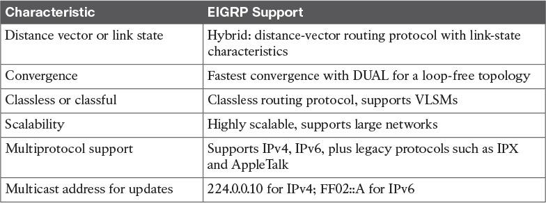
The CCDA should understand EIGRP-specific characteristics and benefits. Table 10-8 provides a summary for reference.
IS-IS
IS-IS is an International Organization for Standardization (ISO) dynamic routing specification. IS-IS is described in ISO/IEC 10589, reprinted by the Internet Engineering Task Force (IETF) as RFC 1195. IS-IS is a link-state routing protocol that floods link-state information throughout the network to build a picture of network topology. IS-IS was primarily intended for routing OSI Connectionless Network Protocol (CNLP) packets, but has the capability to route IP packets. IP packet routing uses Integrated IS-IS, which provides the capability to route protocols such as IP.
IS-IS is a common alternative to other powerful routing protocols such as OSPF and EIGRP in large networks. Although not seen much in enterprise networks, IS-IS is commonly used for internal routing in large ISP networks. IS-IS is also getting more use in data center technologies such as Overlay Transport Virtualization (OTV) and fabric path. As with OSPF, IS-IS uses the Dijkstra algorithm to calculate the shortest path tree (SPF) as well as uses link-state packets (LSPs) instead of OSPF link-state advertisements (LSAs). Also, both are not proprietary protocols.
IS-IS creates two levels of hierarchy, with Level 1 for intra-area routing and Level 2 for inter-area routing. IS-IS distinguishes between Level 1 and Level 2 intermediate systems (ISs). Level 1 ISs communicate with other Level 1 ISs in the same area. Level 2 ISs route between Level 1 areas and form an inter-area routing backbone. Hierarchical routing simplifies backbone design because Level 1 ISs only need to know how to get to the nearest Level 2 IS.
In IS-IS, a router is usually the IS, and personal computers, workstations, and servers are end systems (ESs). ES-to-IS links are Level 0.
IS-IS Metrics
IS-IS, as originally defined, uses a composite metric with a maximum path value of 1024. The required default metric is arbitrary and typically assigned by a network administrator. By convention, it is intended to measure the capacity of the circuit for handling traffic, such as its throughput in bits per second. Higher values indicate a lower capacity. Any single link can have a maximum value of 64. IS-IS calculates path values by summing link values. The standard set the maximum metric values to provide the granularity to support various link types, while at the same time ensuring that the shortest-path algorithm used for route computation is reasonably efficient.
In Cisco routers, all interfaces have a default metric of 10. The administrator must configure the interface metric to get a different value. This small metric value range has proved insufficient for large networks and provides too little granularity for new features such as traffic engineering and other applications, especially with high-bandwidth links. Cisco IOS software addresses this issue with the support of a 24-bit metric field, the so-called “wide metric.” Wide metrics are also required for route leaking. Using the new metric style, link metrics now have a maximum value of 16,777,215 (224 – 1) with a total path metric of 4,261,412,864 (254 × 224 = 232). Deploying IS-IS in the IP network with wide metrics is recommended for enabling finer granularity and supporting future applications such as traffic engineering.
IS-IS also defines three optional metrics (costs): delay, expense, and error. Cisco routers do not support the three optional metrics. The wide metric noted earlier uses the octets reserved for these metrics.
IS-IS Operation and Design
This subsection discusses IS-IS areas, designated routers, authentication, and the Network Entity Title (NET). IS-IS defines areas differently from OSPF; area boundaries are links and not routers. IS-IS has no BDRs. Because IS-IS is an OSI protocol, it uses a NET to identify each router.
IS-IS NET Addressing
Although you can configure IS-IS to route IP, the communication between routers uses OSI PDUs. The NET is the OSI address used for each router to communicate with OSI PDUs. A NET address ranges from 8 to 20 bytes in length and is hexadecimal. It consists of an Authority and Format Identifier (AFI), area ID, system ID, and selector (SEL), as shown in Figure 10-14. The system ID must be unique within the network. An example of an IS-IS NET is 49.0001.1290.6600.1001.00, which consists of the following parts:
![]() AFI: 49
AFI: 49
![]() Area ID: 0001
Area ID: 0001
![]() SEL: 00
SEL: 00
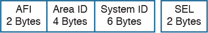
Level 2 routers use the area ID. The system ID must be the same length for all routers in an area. For Cisco routers, it must be 6 bytes in length. Usually, a router MAC address identifies each unique router. The SEL is configured as 00. You configure the NET with the router isis command. In this example, the domain authority and format identifier (AFI) is 49, the area is 0001, the system ID is 00aa.0101.0001, and the SEL is 00:
router isis
net 49.0001.00aa.0101.0001.00
IS-IS DRs
As with OSPF, IS-IS selects DRs on multiaccess networks. It does not choose a backup DR as does OSPF. By default, the priority value is 64. You can change the priority value to a value from 0 to 127. If you set the priority to 0, the router is not eligible to become a DR for that network. IS-IS uses the highest system ID to select the DR if there is a tie with the priorities. On point-to-point networks, the priority is 0 because no DR is elected. In IS-IS, all routers in a multiaccess network establish adjacencies with all others in the subnetwork, and IS-IS neighbors become adjacent upon the discovery of one another. Both these characteristics are different from OSPF behavior.
IS-IS Areas
IS-IS uses a two-level hierarchy. Routers are configured to route Level 1 (L1), Level 2 (L2), or both Level 1 and Level 2 (L1/L2). Level 1 routers are like OSPF internal routers in a Cisco totally stubby area. An L2 router is similar to an OSPF backbone router. A router that has both Level 1 and 2 routes is similar to an OSPF area border router (ABR). IS-IS does not define a backbone area like OSPF’s area 0, but you can consider the IS-IS backbone a continuous path of adjacencies among Level 2 ISs.
The L1/L2 routers maintain a separate link-state database for the L1 routes and L2 routes. Also, the L1/L2 routers do not advertise L2 routes to the L1 area. L1 routers do not have information about destinations outside the area and use L1 routes to the L1/L2 routers to reach outside destinations.
As shown in Figure 10-15, IS-IS areas are not bounded by the L1/L2 routers but by the links between L1/L2 routers and L2 backbone routers.

IS-IS Authentication
IS-IS supports three types of clear-text authentication: link authentication, area authentication, and domain authentication. All these types support only cleartext password authentication. Recently, an RFC draft has added support for an IS-IS MD5. The design recommendation is to not use any plaintext authentication and to use MD5 hash for authentication. With MD5, a cryptographic hash is used instead of plaintext, and the password is never included in the PDU, thus making it more secure.
Routers in a common subnetwork (Ethernet, private line) use link authentication. The clear-text password must be common only between the routers in the link. Level 1 and Level 2 routes use separate passwords. With area authentication, all routers in the area must use authentication and must have the same password.
Only L2 and L1/L2 routers use domain authentication. All L2 and L1/L2 routers must be configured for authentication and must use the same password.
IS-IS Summary
The characteristics of IS-IS follow:
![]() Link-state protocol.
Link-state protocol.
![]() Uses OSI CNLP to communicate with routers.
Uses OSI CNLP to communicate with routers.
![]() Classless protocol (supports VLSMs and CIDR).
Classless protocol (supports VLSMs and CIDR).
![]() Default metric is set to 10 for all interfaces.
Default metric is set to 10 for all interfaces.
![]() Single metric: single link max = 64, path max = 1024.
Single metric: single link max = 64, path max = 1024.
![]() Sends partial route updates only when there are changes.
Sends partial route updates only when there are changes.
![]() Authentication with cleartext passwords.
Authentication with cleartext passwords.
![]() Administrative distance is 115.
Administrative distance is 115.
![]() Used in large networks. Sometimes attractive as compared to OSPF and EIGRP.
Used in large networks. Sometimes attractive as compared to OSPF and EIGRP.
![]() Described in ISO/IEC 10589; reprinted by the IETF as RFC 1142.
Described in ISO/IEC 10589; reprinted by the IETF as RFC 1142.
References and Recommended Readings
Bruno, A. CCIE Routing and Switching Exam Certification Guide. Indianapolis: Cisco Press, 2002.
RFC 1058: Routing Information Protocol, www.ietf.org/rfc.
RFC 2453: RIP Version 2, www.ietf.org/rfc.
RFC 2328: OSPF Version 2, www.ietf.org/rfc.
RFC 1142: OSI IS-IS Intra-domain Routing Protocol, www.ietf.org/rfc.
Doyle, J. Routing TCP/IP, Volume I. Indianapolis: Cisco Press, 1998.
“Enhanced IGRP,” www.cisco.com/univercd/cc/td/doc/cisintwk/ito_doc/en_igrp.htm.
“Enhanced Interior Gateway Routing Protocol,” www.cisco.com/en/US/tech/tk365/tk207/technologies_white_paper09186a0080094cb7.shtml.
“Implementing EIGRP for IPv6,” www.cisco.com/en/US/partner/products/sw/iosswrel/ps5187/products_configuration_guide_chapter09186a00805fc867.html#wp1049317.
RFC 1723: RIP Version 2 – Carrying Additional Information, www.ietf.org/rfc.
RFC 2080: RIPng for IPv6, www.ietf.org/rfc.
RFC 1321: The MD5 Message-Digest Algorithm, www.ietf.org/rfc.
“Routing Information Protocol,” www.cisco.com/univercd/cc/td/doc/cisintwk/ito_doc/rip.htm.
“Tech Notes: How Does Unequal Cost Path Load Balancing (Variance) Work in IGRP and EIGRP?”, http://www.cisco.com/c/en/us/support/docs/ip/enhanced-interior-gateway-routing-protocol-eigrp/13677-19.html.
RFC 7142: Reclassification of RFC 1142 to Historic, www.ietf.org/rfc
RFC 1195: Use of OSI IS-IS for Routing in TCP/IP and Dual Environments, www.ietf.org/rfc.
RFC 5302: Domain-Wide Prefix Distribution with Two-Level IS-IS, www.ietf.org/rfc.
EIGRP Stub Router Functionality, http://www.cisco.com/en/US/technologies/tk648/tk365/technologies_white_paper0900aecd8023df6f.html
“IPv6 Deployment Strategies,” www.cisco.com/en/US/docs/ios/solutions_docs/ipv6/IPv6dswp.html#wp1028199.
Exam Preparation Tasks
Review All Key Topics
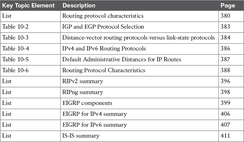
Review the most important topics in the chapter, noted with the Key Topic icon in the outer margin of the page. Table 10-9 provides a reference of these key topics and the page numbers on which each is found.
Complete Tables and Lists from Memory
Print a copy of Appendix D, “Memory Tables,” (found on the book website), or at least the section for this chapter, and complete the tables and lists from memory. Appendix E, “Memory Tables Answer Key,” also on the website, includes completed tables and lists to check your work.
Define Key Terms
Define the following key terms from this chapter, and check your answers in the glossary:
Q&A
The answers to these questions appear in Appendix A, “Answers to the ‘Do I Know This Already?’ Quizzes and Q&A Questions.” For more practice with exam format questions, use the exam engine on the CD.
1. True or false: Link-state routing protocols send periodic routing updates.
2. True or false: RIPv2 was created to support IPv6.
3. True or false: The path with the lowest cost is preferred.
4. True or false: A link with a reliability of 200/255 is preferred over a link with a reliability of 10/255.
5. True or false: A link with a load of 200/255 is preferred over a link with a load of 10/255.
6. On a router, both EIGRP and OSPF have internal routes to 198.168.10.0/24. Which route is injected into the routing table?
7. On a router, both RIPv2 and IS-IS have a route to 198.168.10.0/24. Which route is injected into the routing table?
8. On a router, EIGRP has a route to the destination with a prefix of /28, and OSPF has a route to the destination with a prefix of /30. Which is used to reach the destination?
9. Which of the following is the best measurement of an interface’s reliability and load?
a. Reliability 255/255, load 1/255
b. Reliability 255/255, load 255/255
c. Reliability 1/255, load 1/255
d. Reliability 1/255, load 255/255
10. Which routing protocols permit an explicit hierarchical topology?
a. BGP
b. EIGRP
c. IS-IS
d. RIP
e. OSPF
f. B and D
g. C and E
11. What routing protocol parameter is concerned with how long a packet takes to travel from one end to another in the internetwork?
12. For what routing protocol metric is the value of a Fast Ethernet interface calculated as 108/108 = 1?
13. Match the loop-prevention technique (numerals) with its description (letters).
i. Split horizon
ii. Poison reverse
iii. Triggered updates
iv. Counting to infinity
a. Sends an infinite metric from which the route was learned
b. Drops a packet when the hop count limit is reached
c. Suppresses a route announcement from which the route was learned
d. Sends a route update when a route changes
14. True or false: Link-state routing protocols are more CPU and memory intensive than distance-vector routing protocols.
15. Which routing protocols would you select if you needed to take advantage of VLSMs? (Select all that apply.)
a. RIPv1
b. RIPv2
c. IGRP
d. EIGRP
e. OSPF
f. IS-IS
16. Which standards-based protocol would you select in a large IPv6 network?
a. RIPng
b. OSPFv3
c. EIGRP for IPv6
d. RIPv2
17. Which of the following routing protocols are fast in converging when a change in the network occurs? (Select three.)
a. RIPv1
b. RIPv2
c. EIGRP
d. OSPF
e. IS-IS
f. BGP
18. If you are designing a large corporate network that cannot be designed in a hierarchy, which routing protocol would you recommend?
a. RIPv1
b. RIPv2
c. EIGRP
d. OSPF
e. IS-IS
f. BGP
19. Which routing protocols support VLSMs? (Select all that apply.)
a. RIPv1
b. RIPv2
c. EIGRP
d. OSPF
e. IS-IS
f. All of the above
20. You are connecting your network to an ISP. Which routing protocol would you use to exchange routes?
a. RIPv1
b. RIPv2
c. EIGRP
d. OSPF
e. IS-IS
f. BGP
g. All of the above
21. Which routing protocol requires only Cisco routers on the network?
a. RIPv1
b. RIPv2
c. EIGRP
d. OSPF
e. IS-IS
f. BGP
g. All of the above
22. Which routing protocol would be supported on an IPv6 network with multiple vendor routers?
a. RIPv2
b. EIGRP for IPv6
c. BGPv6
e. RIPv3
f. All of the above
g. B and D
23. Which of the following characteristics are implemented differently between distance-vector and link-state routing protocols?
a. IP route tables
b. Route information distribution
c. Routing tables
d. Forwarding of traffic
e. Verification of route information sources
f. Administrative distance
24. Which two statements are true for IGPs and EGPs?
a. IGPs can be substituted with static routing.
b. IGPs are better at finding the fastest paths across the network.
c. IGPs must converge quickly, but EGPs do not.
d. IGPs are for inter-autonomous system connections, EGPs are used for intra-autonomous system connections.
25. How is convergence related to routing information?
a. The speed of convergence affects the frequency of routing updates.
b. The faster the convergence, less consistent routing information is produced.
c. The faster the convergence, more consistent routing information is produced.
d. There is no relation between convergence and routing information consistency.
26. What is a major advantage of a classless structured network over a classless network?
a. There is less overhead in classless networks.
b. There is more overhead in classless networks.
c. Less IP addresses are used in classful networks.
d. Classless networks do not have advantages over classful networks.
27. Which two EIGRP features make it appropriate for a company’s network?
a. Slow convergence
b. VLSM support
c. DUAL
d. Automatic summarization
e. Multivendor support
28. Match the protocol with the characteristic.
i. EIGRP for IPv6
ii. RIPv2
iii. RIPng
iv. EIGRP
a. Uses multicast FF02::9
b. Uses multicast 224.0.0.9
c. Uses multicast 224.0.0.10
d. Uses multicast FF02::A
29. A small network is experiencing excessive broadcast traffic and slow response times. The current routing protocol is RIPv1. What design changes would you recommend?
a. Migrate to RIPv2.
b. Migrate to RIPng.
c. Migrate to EIGRP for IPv4.
d. Migrate to EIGRPv6.
30. Match the EIGRP component with its description.
i. RTP
ii. DUAL
iii. Protocol-dependent modules
iv. Neighbor discovery
a. An interface between DUAL and IPX RIP, IGRP, and AppleTalk
b. Used to deliver EIGRP messages reliably
c. Builds an adjacency table
d. Guarantees a loop-free network
31. Match each EIGRP parameter with its description.
i. Feasible distance
ii. Successor
iii. Feasible successor
iv. Active state
a. The best path selected by DUAL.
b. The successor is down.
c. The lowest calculated metric of a path to reach the destination.
d. The second-best path.
32. On an IPv6 network, you have RIPng and EIGRP running. Both protocols have a route to destination 10.1.1.0/24. Which route gets injected into the routing table?
a. The RIPng route
b. The EIGRP route
d. Neither route because of a route conflict
33. Which routing protocol should be used if the network requirements include fastest convergence time and unequal load balancing?
a. BGP
b. OSPF
c. EIGRP
d. RIPv2
34. Which IGP protocol is a common alternative to EIGRP and OSPF as a routing protocol for large service provider networks?
a. OSPFv3
b. RIPv2
c. BGP4
d. IS-IS
35. What is the default IS-IS metric for a T1 interface?
a. 5
b. 10
c. 64
d. 200
36. In IS-IS networks, the backup designated router (BDR) forms adjacencies to what routers?
a. Only to the DR.
b. To all routers.
c. The BDR only becomes adjacent when the DR is down.
d. There is no BDR is IS-IS.
37. Which routing protocol converges most quickly?
a. BGP
b. OSPF
c. EIGRP
d. RIPv2
e. IS-IS
38. Which routing protocol allows for unequal cost multipath routing?
a. IS-IS
b. OSPF
c. EIGRP
d. RIPv2
39. Which two link-state routing protocols support IPv6?
a. BGP4
b. EIGRP
c. OSPF
d. RIPng
e. IS-IS
40. Select those answers that are characteristics of EIGRP? (Select four.)
a. ASN and K values must match to form neighbors
b. Can use multiple unequal paths
c. Summary routes have an AD of 150.
d. External routes have an AD of 170.
e. Exchanges the full routing table every 60 seconds.
f. Uses multicast address 224.0.0.10 for updates.
g. Does not support MD5 authentication
41. A hierarchical design of EIGRP helps with which of the following? (Select two.)
a. Redistribution
b. Route summarization
c. Faster convergence
d. Load balancing
42. Which are design considerations with EIGRP?
a. The neighbor command is used to enable unicast communication.
b. The neighbor command can be used to establish adjacency with non-Cisco routers.
c. The ASN and K values must match to establish neighbors.
d. Virtual links can be used to establish neighbors over an area.
43. Which are the two fastest converging routing protocols?
a. IS-IS
b. OSPF
c. EIGRP
d. RIPv2
e. BGP4
44. Which routing protocol uses multicast FF02::A and Next Header protocol 88?
a. IS-IS for IPv6
b. OSPFv3
c. EIGRP for IPv6
d. RIPng
45. What is the system ID of the following NET?
49.0001.1900.6500.0001.00
a. 49.0001
b. 0001.1900.6500
c. 1900.6500.0001
d. 0001.00
46. Loops can cause broadcast storms and congestion. How do distance-vector routing protocols handle this? (Select all that apply.)
a. Counting to infinity
b. Poison reverse
c. Split horizon
d. Vector routing
47. EIGRP has a route with a metric of 20. There are two feasible successors with metrics of 35 and 45. If the variance 2 command is invoked, how many active routes are there for this route?
a. 1.
b. 2.
c. 3.
d. Variance has to be used for equal-cost routes.
48. Which routing protocol has the highest admin distance?
a. RIP
b. EIGRP
c. OSPF
d. IS-IS
c. BGP
49. Which routing protocol has the lowest admin distance?
a. RIP
b. EIGRP
c. OSPF
d. IS-IS
c. iBGP
50. Which routing protocol represents each column of Table 10-10?
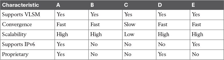
Answer questions 51–53 based on Figure 10-16.
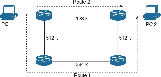
51. A user performs a Telnet from PC 1 to PC 2. If the metric used by the configured routing protocol is the bandwidth parameter, which route will the packets take?
a. Route 1.
b. Route 2.
c. Neither, because the information is insufficient.
d. One packet takes Route 1, the following packet takes Route 2, and so on.
52. A user performs a Telnet from PC 1 to PC 2. If the metric used by the configured routing protocol is hop count, which route will the packets take?
a. Route 1.
b. Route 2.
c. Neither, because the information is insufficient.
d. One packet takes Route 1, the following packet takes Route 2, and so on.
53. A user performs a Telnet from PC 1 to PC 2. If the metric used by the configured routing protocol is OSPF cost, which route will the packets take?
a. Route 1.
b. Route 2.
c. Neither, because the information is insufficient.
d. One packet takes Route 1, the following packet takes Route 2, and so on.
Use Figure 10-17 to answer the remaining questions.
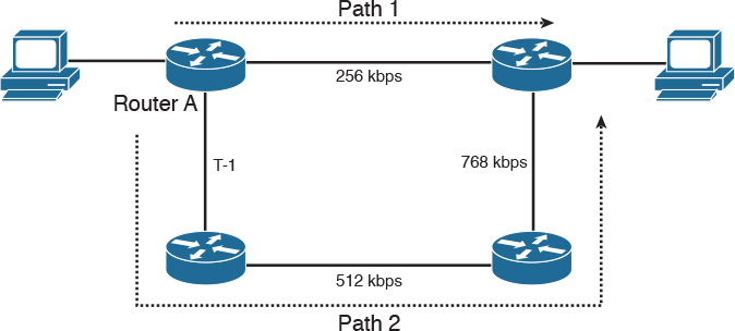
54. By default, if RIPv2 is enabled on all routers, what path is taken?
a. Path 1
b. Path 2
c. Unequal load balancing with Path 1 and Path 2
d. Equal load balancing with Path 1 and Path 2
55. By default, if RIPng is enabled on all routers, what path is taken?
a. Path 1
b. Path 2
c. Unequal load balancing with Path 1 and Path 2
d. Equal load balancing with Path 1 and Path 2
56. By default, if EIGRP is enabled on all routers, what path is taken?
a. Path 1
b. Path 2
c. Unequal load balancing with Path 1 and Path 2
d. Equal load balancing with Path 1 and Path 2
57. EIGRP is configured on the routers. If it is configured with the variance command, what path is taken?
a. Path 1
b. Path 2
c. Unequal load sharing Path 1 and Path 2
d. Equal load balancing with Path 1 and Path 2
58. By default, if EIGRP for IPv6 is enabled on all routers, and this is an IPv6 network, what path is taken?
a. Path 1
b. Path 2
c. Unequal load balancing with Path 1 and Path 2
d. Equal load balancing with Path 1 and Path 2
59. By default, if IS-IS is enabled on all routers, and this is an IPv6 network, what path is taken?
a. Path 1
b. Path 2
c. Unequal load balancing with Path 1 and Path 2