Chapter 11. OSPF, BGP, Route Manipulation, and IP Multicast
This chapter covers the following subjects:
This chapter reviews the characteristics and design issues of the Open Shortest Path First Version 2 (OSPFv2) routing protocol. For IPv6 networks, OSPFv3 is also covered. OSPFv2 and OSPFv3 are link-state routing protocols. They do not broadcast their route tables as distance-vector routing protocols do. Routers using link-state routing protocols send information about the status of their interfaces to all other routers in the area. Then they perform database computations to determine the shortest paths to each destination. This chapter also covers the Border Gateway Protocol (BGP), which is used to exchange routes between autonomous systems. It is most frequently used between enterprises and service providers. The “Route Manipulation” section covers route summarization, route filtering, and redistribution of route information between routing protocols. The CCDA should know where redistribution occurs when required by the network design. This chapter concludes by covering IP multicast protocols.
“Do I Know This Already?” Quiz
The “Do I Know This Already?” quiz helps you identify your strengths and deficiencies in this chapter’s topics.
The 12-question quiz, derived from the major sections in the “Foundation Topics” portion of the chapter, helps you determine how to spend your limited study time.
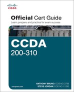
Table 11-1 outlines the major topics discussed in this chapter and the “Do I Know This Already?” quiz questions that correspond to those topics.
1. Which protocol defines an Area Border Router (ABR)?
a. Enhanced Interior Gateway Routing Protocol (EIGRP)
b. Open Shortest Path First (OSPF)
c. Intermediate System-to-Intermediate System (IS-IS)
d. Routing Information Protocol (RIP)
2. Which routing protocols support variable-length subnet masks (VLSMs)?
a. EIGRP
b. OSPF
c. IS-IS
d. A and B
e. A and C
f. B and C
g. A, B, and C
3. What is an ASBR?
a. Area Border Router
b. Autonomous System Boundary Router
c. Auxiliary System Border Router
d. Area System Border Router
4. What is the OSPFv2 link-state advertisement (LSA) type for autonomous system external LSAs?
a. Type 1
b. Type 2
c. Type 3
d. Type 4
e. Type 5
5. What address do you use to multicast to the OSPFv2 designated router (DR)?
a. 224.0.0.1
b. 224.0.0.5
c. 224.0.0.6
d. 224.0.0.10
6. To where are OSPF Type 1 LSAs flooded?
a. The OSPF area
b. The OSPF domain
c. From the area to the OSPF backbone
d. Through the virtual link
7. What OSPFv3 LSA carries address prefixes?
a. Network LSA
b. Summary LSA
c. Inter-area-router LSA
d. Intra-area-prefix LSA
8. What protocol do you use to exchange IP routes between autonomous systems?
a. IGMP
b. eBGP
c. EIGRP
d. OSPF
9. Where should routes be summarized?
a. On the core routers
b. On the distribution routers
c. On the access routers
d. None of the above
10. What is IGMP?
a. Interior Group Management Protocol
b. Internet Group Management Protocol
c. Interior Gateway Routing Protocol
d. Interior Gateway Media Protocol
11. How many bits are mapped from the Layer 3 IPv4 multicast address to a Layer 2 MAC address?
a. 16 bits
b. 23 bits
c. 24 bits
d. 32 bits
12. What is the administrative distance of eBGP routes?
a. 20
b. 100
c. 110
d. 200
Foundation Topics
This chapter covers the link-state routing protocol OSPF. OSPF is an Interior Gateway Protocol (IGP) used within an autonomous system. Is it the most widely used IGP in enterprises, government networks, and service providers. OSPFv2 is used for IPv4 networks, and OSPFv3 is used for IPv6 networks. IS-IS is another link-state routing protocol covered in the previous chapter.
The “BGP” section covers the characteristics and design of BGP. eBGP exchanges routes between autonomous systems. eBGP is commonly used between enterprises and their service providers.
The section “Route Manipulation” covers how you use policy-based routing (PBR) to change packets’ destination addresses based on policies. This section also covers route summarization, filtering, and redistribution of route information between routing protocols.
The section “IP Multicast Review” covers multicast protocols such as Internet Group Management Protocol (IGMP), Cisco Group Management Protocol (CGMP), and Protocol Independent Multicast (PIM).
OSPFv2
RFC 2328 defines OSPFv2, a link-state routing protocol that uses Dijkstra’s shortest path first (SPF) algorithm to calculate paths to destinations. OSPFv2 is used in IPv4 networks. OSPF was created for its use in large networks where RIP failed. OSPF improved the speed of convergence, provided for the use of variable-length subnet masks (VLSMs), and improved the path calculation.
In OSPF, each router sends link-state advertisements (LSAs) about itself and its links to all other routers in the area. Note that it does not send routing tables but rather link-state information about its interfaces. Then, each router individually calculates the best routes to the destination by running the SPF algorithm. Each OSPF router in an area maintains an identical database describing the area’s topology. The routing table at each router is individually constructed using the local copy of this database to construct a shortest-path tree.
OSPFv2 is a classless routing protocol that permits the use of VLSMs. With Cisco routers, OSPF also supports equal-cost multipath load balancing and neighbor authentication. OSPF uses multicast addresses to communicate between routers. OSPF uses IP protocol 89.
This section covers OSPF theory and design concepts. It discusses OSPF LSAs, area types, and router types. OSPF uses a two-layer hierarchy with a backbone area at the top and all other areas below. Routers send LSAs informing other routers of the status of their interfaces. The use of LSAs and the characteristics of OSPF areas are important concepts to understand for the exam.
OSPFv2 Metric
The metric that OSPFv2 uses is cost. It is an unsigned 16-bit integer in the range of 1 to 65,535. The default cost for interfaces is calculated based on the bandwidth in the formula 108 / BW, where BW is the bandwidth of the interface expressed as a full integer of bits per second (bps). If the result is smaller than 1, the cost is set to 1. A 10BASE-T (10 Mbps = 107 bps) interface has a cost of 108 / 107 = 10. OSPF performs a summation of the costs to reach a destination; the lowest cost is the preferred path. Table 11-2 shows some sample interface metrics.

The default reference bandwidth used to calculate OSPF costs is 108 (cost = 108 / BW). Notice that for technologies that support speeds greater than 100 Mbps, the default metric gets set to 1 without regard for the network’s different capabilities (speed).
Because OSPF was developed prior to high-speed WAN and LAN technologies, the default metric for 100 Mbps was 1. Cisco provides a method to modify the default reference bandwidth. The cost metric can be modified on every interface. It is highly recommended that you change the default reference bandwidth to a higher number on all routers in the OSPF network if OSPF links have a speed higher than 100 Mbps.
OSPFv2 Adjacencies and Hello Timers
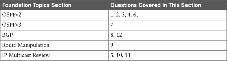
OSPF uses Hello packets for neighbor discovery. The default Hello interval is 10 seconds (30 seconds for nonbroadcast multiaccess [NBMA] networks). For point-to-point networks, the Hello interval is 10 seconds. Hellos are multicast to 224.0.0.5 (ALLSPFRouters). Hello packets include such information as the router ID, area ID, authentication, and router priority.
After two routers exchange Hello packets and set two-way communication, they establish adjacencies.
Figure 11-1 shows a point-to-point network and an NBMA network.
For point-to-point networks, valid neighbors always become adjacent and communicate using multicast address 224.0.0.5. For broadcast (Ethernet) and NBMA networks (Frame Relay), all routers become adjacent to the designated router (DR) and backup designated router (BDR), but not to each other. All routers reply to the DR and BDR using the multicast address 224.0.0.6. The section “OSPF DRs” covers the DR concept.
On OSPF point-to-multipoint nonbroadcast networks, it is necessary to configure the set of neighbors that are directly reachable over the point-to-multipoint network. Each neighbor is identified by its IP address on the point-to-multipoint network. Nonbroadcast point-to-multipoint networks do not elect DRs, so the DR eligibility of configured neighbors is undefined. OSPF communication in point-to-point networks use unicast or multicast addresses for neighbor communication.
OSPF virtual links unicast OSPF packets. Later, the section “Virtual Links” discusses virtual links.
OSPFv2 Areas

As a network grows, the initial flooding and database maintenance of LSAs can burden a router’s CPU. OSPF uses areas to reduce these effects. An area is a logical grouping of routers and links that divides the network. Routers share link-state information with only the routers in their areas. This setup reduces the size of the database and the cost of computing the SPF tree at each router.
Using a topology with multiple areas provides the following benefits:
![]() The segmentation of the network reduces the number of SFP tree calculations.
The segmentation of the network reduces the number of SFP tree calculations.
![]() The segmentation of the network reduces the amount of LSA flooding.
The segmentation of the network reduces the amount of LSA flooding.
![]() Multi-area design allows for summarization at the Area Border Routers (ABRs).
Multi-area design allows for summarization at the Area Border Routers (ABRs).
![]() One OSPF area hides the topology from another area.
One OSPF area hides the topology from another area.
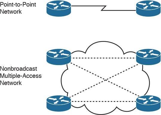
Each area is assigned a 32-bit integer number. Area 0 (or 0.0.0.0) is reserved for the backbone area. Every OSPF network should have a backbone area. The backbone area must exist in any internetwork using OSPF over multiple areas as a routing protocol. As you can see in Figure 11-2, communication between Area 1 and Area 2 must flow through Area 0. This communication can be internal to a single router that has interfaces directly connected to Areas 0, 1, and 2.
Intra-area traffic is packets passed between routers in a single area.
OSPF Area Design Considerations
The CCDA should be aware of a few considerations in the design of OSPF areas. First, in a hub-and-spoke design, you have a remote branch keep the OSPF boundary at the hub side, as shown in Figure 11-3. This allows the branch router to only calculate SPFs within its own area and limits the LSA flooding. If the OSPF Area 0 boundary was extended to the branch, then the branch router would have to do OSPF calculations for Area 0 and its own area, and LSAs would flood over the WAN link.

The second design consideration is not to group remote branches into a single area. Having all remote branches in the same area is not scalable. Instead, place each remote branch in its own area to limit LSA flooding and SPF recalculations.
OSPF Router Types
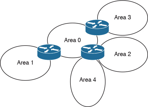
OSPF classifies participating routers based on their place and function in the area architecture. Figure 11-4 shows OSPF router types.

Table 11-3 explains each router type in Figure 11-4.
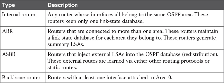
Tip
An OSPF router can be an ABR, an ASBR, and a backbone router at the same time. The router is an ABR if it has an interface on Area 0 and another interface in another area. The router is a backbone router if it has one or more interfaces in Area 0. The router is an ASBR if it redistributes external routes into the OSPF network.
OSPF DRs
On multiaccess networks (such as Ethernet), some routers get selected as DRs. The purpose of the DR is to collect LSAs for the multiaccess network and to forward the LSA to all non-DR routers; this arrangement reduces the amount of LSA traffic generated. A router can be the DR for one multiaccess network and not the DR in another attached multiaccess network.
The DR also floods the network LSAs to the rest of the area. OSPF also selects a BDR; it takes over the function of the DR if the DR fails. Both the DR and BDR become adjacent to all routers in the multiaccess network. All routers that are not DR and BDR are sometimes called DRothers. These routers are only adjacent to the DR and BDR. The DR generates a Type 2 (network) LSA, which advertises all other routers on the multiaccess segment. This allows the DRothers routers to get the Type 1 LSAs. OSPF routers multicast LSAs only to adjacent routers. DRothers multicast packets to the DR and BDR using the multicast address 224.0.0.6 (ALLDRouters). The DR floods updates using ALLSPFRouters (224.0.0.5).
DR and BDR selection is based on an OSPF DR interface priority. The default value is 1, and the highest priority determines the DR. In a tie, OSPF uses the numerically highest router ID. The router ID is the IP address of the configured loopback interface. The router ID is the highest configured loopback address, or if the loopback is not configured, it’s the highest physical address. Routers with a priority of 0 are not considered for DR/BDR selection. The dotted lines in Figure 11-5 show the adjacencies in the network.
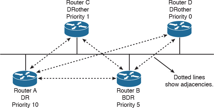
In Figure 11-5, Router A is configured with a priority of 10, and Router B is configured with a priority of 5. Assuming that these routers are turned on simultaneously, Router A becomes the DR for the Ethernet network. Router C has a lower priority, becoming adjacent to Router A and Router B but not to Router D. Router D has a priority of 0 and therefore is not a candidate to become a DR or BDR.
If you introduce a new router to the network with a higher priority than that of the current DR and BDR, it does not become the selected DR unless both the DR and BDR fail. If the DR fails, the current BDR becomes the DR.
LSA Types
OSPF routers generate LSAs that are flooded within an area, between areas, and throughout the entire autonomous system. OSPF defines different LSA types for participating routers, DRs, ABRs, and ASBRs. Understanding the LSA types can help you with other OSPF concepts. Table 11-4 describes the major LSA types. You will need to know OSPF LSAs by type code (number) and by type name. Note that there are other LSA types that are not covered in this book.

Type 1 and Type 2 LSAs are intra-area LSAs that have an area-flooding scope. Type 3 LSAs are a summary of destinations outside the local area but within the OSPF domain. Type 4 LSAs provide reachability about the ASBR. Type 3 and Type 4 LSAs are inter-area LSAs that have an area-flooding scope. ABRs exchange Type 3 and Type 4 LSAs. Type 5 LSAs advertise external destinations. Type 5 LSAs have a domain-flooding scope, meaning they are flooded throughout all areas. Type 7 LSAs are originated by ASBRs in an NSSA and are similar to the Type 5 LSA and only flooded within the NSSA.
Autonomous System External Path Types
The two types of autonomous system external paths are Type 1 (E1) and Type 2 (E2), and they are associated with Type 5 LSAs. ASBRs advertise external destinations whose cost can be just a redistribution metric (E2) or a redistribution metric plus the costs of each segment (E1) used to reach the ASBR.
By default, external routes are of Type 2, which is the metric (cost) used in the redistribution. Type 1 external routes have a metric that is the sum of the redistribution cost plus the cost of the path to reach the ASBR.
OSPF Stub Area Types
OSPF provides support for stub areas. The concept is to reduce the number of inter-area or external LSAs that get flooded into a stub area. RFC 2328 defines OSPF stub areas. RFC 1587 defines support for NSSAs. Cisco routers use totally stubby areas, such as Area 2, as shown in Figure 11-6.

Stub Areas
Consider Area 1 in Figure 11-6. Its only path to the external networks is via the ABR through Area 0. All external routes are flooded to all areas in the OSPF autonomous system. You can configure an area as a stub area to prevent OSPF external LSAs (Type 5) from being flooded into that area. A single default route is injected into the stub area instead. If multiple ABRs exist in a stub area, all inject the default route. Traffic originating within the stub area routes to the closest ABR.
Note that network summary LSAs (Type 3) from other areas are still flooded into the stub Area 1.
Totally Stubby Areas
Let’s take Area 1 in Figure 11-6 one step further. The only path for Area 1 to get to Area 0 and other areas is through the ABR. A totally stubby area does not flood network summary LSAs (Type 3). It stifles Type 4 LSAs, as well. Like regular stub areas, totally stubby areas do not flood Type 5 LSAs. They send just a single LSA for the default route. If multiple ABRs exist in a totally stubby area, all ABRs inject the default route. Traffic originating within the totally stubby area routes to the closest ABR.
NSSAs
Notice that Area 2 in Figure 11-6 has an ASBR. If this area is configured as an NSSA, it generates the external LSAs (Type 7) into the OSPF system while retaining the characteristics of a stub area to the rest of the autonomous system. There are two options for the ABR. First, the ABR for Area 2 can translate the NSSA external LSAs (Type 7) to autonomous system external LSAs (Type 5) and flood the rest of the internetwork. Second, the ABR is not configured to convert the NSSA external LSAs to Type 5 external LSAs, and therefore the NSSA external LSAs remain within the NSSA.
There is also an NSSA totally stub area. The difference is that the default NSSA has no default route unless the ABR is explicitly configured to advertise one. The NSSA totally stub area does receive a default route.
Virtual Links
OSPF requires that all areas be connected to a backbone router. Sometimes, WAN link provisioning or failures can prevent an OSPF area from being directly connected to a backbone router. You can use virtual links to temporarily connect (virtually) the area to the backbone.
As shown in Figure 11-7, Area 4 is not directly connected to the backbone. A virtual link is configured between Router A and Router B. The flow of the virtual link is unidirectional and must be configured in each router of the link. Area 2 becomes the transit area through which the virtual link is configured. Traffic between Areas 2 and 4 does not flow directly to Router B. Instead, the traffic must flow to Router A to reach Area 0 and then pass through the virtual link.

OSPFv2 Router Authentication
OSPFv2 supports the authentication of routes using 64-bit clear text or cryptographic message digest 5 (MD5) authentication. Authentication can be performed on a per-area or per-interface basis. Plaintext authentication passwords do not need to be the same for the routers throughout the area, but they must be the same between neighbors.
MD5 authentication provides higher security than plaintext authentication. As with plaintext authentication, passwords do not have to be the same throughout an area, but they do need to be the same between neighbors.
OSPFv2 Summary
OSPFv2 is used in large enterprise IPv4 networks. The network topology must be hierarchical. OSPF is used in the enterprise campus building access, distribution, and core layers. OSPF is also used in the enterprise data center, WAN/MAN, and branch offices.
The characteristics of OSPFv2 follow:
![]() Link-state routing protocol.
Link-state routing protocol.
![]() Uses IP protocol 89.
Uses IP protocol 89.
![]() Classless protocol (supports VLSMs and CIDR).
Classless protocol (supports VLSMs and CIDR).
![]() Metric is cost (based on interface bandwidth by default).
Metric is cost (based on interface bandwidth by default).
![]() Fast convergence. Uses link-state updates and SPF calculation.
Fast convergence. Uses link-state updates and SPF calculation.
![]() Reduced bandwidth use. Sends partial route updates only when changes occur.
Reduced bandwidth use. Sends partial route updates only when changes occur.
![]() Routes are labeled as intra-area, inter-area, external Type 1, or external Type 2.
Routes are labeled as intra-area, inter-area, external Type 1, or external Type 2.
![]() Support for authentication.
Support for authentication.
![]() Uses the Dijkstra algorithm to calculate the SPF tree.
Uses the Dijkstra algorithm to calculate the SPF tree.
![]() Default administrative distance is 110.
Default administrative distance is 110.
![]() Uses multicast address 224.0.0.5 (ALLSPFRouters).
Uses multicast address 224.0.0.5 (ALLSPFRouters).
![]() Uses multicast address 224.0.0.6 (ALLDRouters).
Uses multicast address 224.0.0.6 (ALLDRouters).
![]() Good scalability. Recommended for large networks.
Good scalability. Recommended for large networks.
OSPFv3
RFC 5340 describes OSPF Version 3 as a routing protocol for IPv6 networks. Note that OSPFv3 is for IPv6 networks only and that it is not backward compatible with OSPFv2 (used in IPv4). OSPF algorithms and mechanisms, such as flooding, router types, designated router election, areas, stub and NSSA, and SPF calculations, remain the same. Changes are made for OSPF to support IPv6 addresses, address hierarchy, and IPv6 for transport. OSPFv3 uses multicast group FF02::5 for all OSPF routers and FF02::6 for all designated routers.
![]() Version number is 3: Obviously, this is a newer version of OSPF, and it runs over IPv6 only.
Version number is 3: Obviously, this is a newer version of OSPF, and it runs over IPv6 only.
![]() Support for IPv6 addressing: New LSAs created to carry IPv6 addresses and prefixes.
Support for IPv6 addressing: New LSAs created to carry IPv6 addresses and prefixes.
![]() Per-link processing: OSPFv2 uses per-subnet processing. With link processing, routers in the same link can belong to multiple subnets.
Per-link processing: OSPFv2 uses per-subnet processing. With link processing, routers in the same link can belong to multiple subnets.
![]() Address semantics removed: Addresses are removed from the router and network LSAs. These LSAs now provide topology information.
Address semantics removed: Addresses are removed from the router and network LSAs. These LSAs now provide topology information.
![]() No authentication in the OSPFv3 protocol: OSPFv3 uses the authentication schemes inherited in IPv6.
No authentication in the OSPFv3 protocol: OSPFv3 uses the authentication schemes inherited in IPv6.
![]() New link LSA: For local-link flooding scope.
New link LSA: For local-link flooding scope.
![]() New intra-area-prefix LSA: Carries all the IPv6 prefix information. Similar to an OSPFv2 router and network LSAs.
New intra-area-prefix LSA: Carries all the IPv6 prefix information. Similar to an OSPFv2 router and network LSAs.
![]() Identifying neighbors by router ID: Neighbors are always identified by the router ID. This does not occur in OSPFv2 point-to-point and broadcast networks.
Identifying neighbors by router ID: Neighbors are always identified by the router ID. This does not occur in OSPFv2 point-to-point and broadcast networks.
![]() Options field changes: Two Options bits, the R-bit and the V6-bit, have been added to the Options field for processing router LSAs during the SPF calculation.
Options field changes: Two Options bits, the R-bit and the V6-bit, have been added to the Options field for processing router LSAs during the SPF calculation.
Note
In OSPFv3, the router IDs, area IDs, and LSA link-state IDs remain at the size of 32 bits. Larger IPv6 addresses cannot be used.
OSPFv3 Areas and Router Types
OSPFv3 retains the same structure and concepts as OSPFv2. The area topology, interfaces, neighbors, link-state database, and routing table remain the same. RFC 2740 does not define new area types or router types.
The OSPF areas shown in Figure 11-2 and the router types shown in Figure 11-4 remain the same. The router types in relation to the OSPF areas are
![]() Internal router: Any router whose interfaces all belong to the same OSPF area. These routers keep only one link-state database.
Internal router: Any router whose interfaces all belong to the same OSPF area. These routers keep only one link-state database.
![]() ABR: Routers that are connected to more than one area, where one area is Area 0. These routers maintain a link-state database for each area they belong to. These routers generate summary LSAs.
ABR: Routers that are connected to more than one area, where one area is Area 0. These routers maintain a link-state database for each area they belong to. These routers generate summary LSAs.
![]() ASBR: Routers that inject external LSAs into the OSPF database (redistribution). These external routes are learned via either other routing protocols or static routes.
ASBR: Routers that inject external LSAs into the OSPF database (redistribution). These external routes are learned via either other routing protocols or static routes.
![]() Backbone router: Routers with at least one interface attached to Area 0.
Backbone router: Routers with at least one interface attached to Area 0.
OSPFv3 LSAs
OSPFv3 retains the LSA types used by OSPFv2 with some modifications and introduces two new LSAs: link LSA and intra-area-prefix.
All LSAs use a common 20-byte header that indicates the LS type, the advertising router, and the sequence number. Figure 11-8 shows the format of the LSA header.

The LS Age indicates the time in seconds since the LSA was generated.
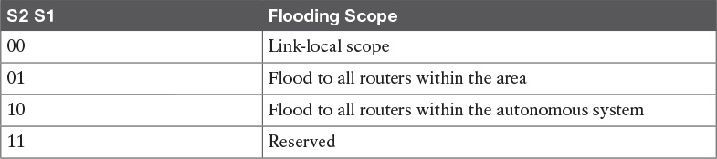
The LS Type indicates the function performed by this LSA. This field includes a U bit and S2 and S1 bits. When the U bit is set to 0, the LSA is flooded only locally. When the U bit is set to 1, the LSA is stored and flooded. The S1 and S2 bits have the functions indicated in Table 11-5.
The Link State ID is used with the LS type and advertising router to identify the link-state database. The Advertising Router field contains the 32-bit router ID of the router that generated the LSA. The LS Sequence Number is used to detect old or duplicate LSAs. The LS Checksum is for error checking. The Length field indicates the length of the LSA, including the header.
Table 11-6 summarizes the nine LSAs that can be used in OSPF. Most LSAs retain the same function used in OSPFv2 for IPv4. OSPFv3 initially supported IPv6 networks only, but it has been updated to support both IPv6 and IPv4 networks.

Router LSAs describe the cost and state of all the originating router’s interfaces. These LSAs are flooded within the area only. Router LSAs are LS type 0x2001. No IPv6 prefixes are contained in this LSA.
Network LSAs are originated by DRs in broadcast or NBMA networks. They describe all routers attached to the link that are adjacent to the DR. These LSAs are flooded within the area only. The LS type is 0x2002. No IPv6 prefixes are contained in this LSA.
Inter-area-prefix LSAs describe routes to IPv6 prefixes that belong to other areas. They are similar to OSPFv2 type 3 summary LSAs. The inter-area-prefix LSA is originated by the ABR and has an LS type of 0x2003. It is also used to send the default route in stub areas. These LSAs are flooded within the area only.
Each inter-area-router LSA describes a route to a router in another area. It is similar to OSPF Type 4 summary LSAs. It is originated by the ABR and has an LS type of 0x2004. These LSAs are flooded within the area only.
Autonomous system-external LSAs describe networks that are external to the autonomous system. These LSAs are originated by ASBRs, have an LS type of 0x4005, and therefore are flooded to all routers in the autonomous system.
The group-membership LSA describes the directly attached networks that contain members of a multicast group. This LSA is limited to the area and has an LS type of 0x2006. This LSA is described further in RFC 1584. This LSA is not supported in Cisco IOS Software.
Type 7 LSAs describe networks that are external to the autonomous system, but they are flooded to the NSSA area only. NSSAs are covered in RFC 1587. This LSA is generated by the NSSA ASBR and has a type of 0x2007.
Link LSAs describe the router’s link-local address and a list of IPv6 prefixes associated with the link. This LSA is flooded to the local link only and has a type of 0x0008.
The intra-area-prefix LSA is a new LSA type that is used to advertise IPv6 prefixes associated with a router, a stub network, or an associated transit network segment. This LSA contains information that used to be part of the router LSAs and network LSAs.
OSPFv3 Summary
OSPFv3 is used in large enterprise IPv6 networks. The network topology must be hierarchical. OSPF is used in the enterprise campus building access, distribution, and core layers. OSPF is also used in the enterprise data center, WAN/MAN, and branch offices.
The characteristics of OSPFv3 follow:
![]() Link-state routing protocol for IPv6.
Link-state routing protocol for IPv6.
![]() Uses IPv6 Next Header 89.
Uses IPv6 Next Header 89.
![]() Metric is cost (based on interface bandwidth by default).
Metric is cost (based on interface bandwidth by default).
![]() Sends partial route updates only when changes occur.
Sends partial route updates only when changes occur.
![]() Routes are labeled as intra-area, inter-area, external Type 1, or external Type 2.
Routes are labeled as intra-area, inter-area, external Type 1, or external Type 2.
![]() Uses IPv6 for authentication.
Uses IPv6 for authentication.
![]() Uses the Dijkstra algorithm to calculate the SPF tree.
Uses the Dijkstra algorithm to calculate the SPF tree.
![]() Default administrative distance is 110.
Default administrative distance is 110.
![]() Uses multicast address FF02::5 (ALLSPFRouters).
Uses multicast address FF02::5 (ALLSPFRouters).
![]() Uses multicast address FF02::6 (ALLDRouters).
Uses multicast address FF02::6 (ALLDRouters).
![]() Fast convergence, scalable, and reduces bandwidth.
Fast convergence, scalable, and reduces bandwidth.
![]() Recommended for large IPv6 networks.
Recommended for large IPv6 networks.
BGP
This section covers Border Gateway Protocol theory and design concepts. The current version of BGP, Version 4, is defined in RFC 4271 (January 2006). BGP is an interdomain routing protocol. What this means is that you use BGP to exchange routing information between autonomous systems. (It is used for inter-autonomous system routing.) The primary function of BGP is to provide and exchange network-reachability information between domains or autonomous systems. BGP is a path-vector protocol. BGP is best suited for setting routing policies between autonomous systems. In the enterprise campus architecture, BGP is used in the Internet connectivity module.
BGP is the de facto standard for routing between service providers on the Internet because of its rich features. You can also use it to exchange routes in large internal networks. The Internet Assigned Numbers Authority (IANA) reserved TCP port 179 to identify the BGP protocol. BGPv4 was created to provide CIDR, a feature that was not present in the earlier versions of BGP. BGP is a path-vector routing protocol; it is neither a distance-vector nor link-state routing protocol.
RFC 1519 describes CIDR, which provides the capability to forward packets based on IP prefixes only, with no concern for IP address class boundaries. CIDR was created as a means to constrain the growth of the routing tables in the Internet core through the summarization of IP addresses across network class boundaries. The early 1990s saw an increase in the growth of Internet routing tables and a reduction in Class B address space. CIDR provides a way for service providers to assign address blocks smaller than a Class B network but larger than a Class C network.
BGP Neighbors
BGP is usually configured between two directly connected routers that belong to different autonomous systems. Each autonomous system is under different technical administration. BGP is frequently used to connect the enterprise to service providers and to interconnect service providers, as shown in Figure 11-9. The routing protocol within the enterprise could be any Interior Gateway Protocol (IGP). Common IGP choices include RIPv2, EIGRP, OSPF, and IS-IS. BGPv4 is the only deployed Exterior Gateway Protocol (EGP).

BGP is an interdomain routing protocol that allows BGP speakers residing in different autonomous systems to exchange routing (NLRI) information. An autonomous system is a collection of devices under common administration. BGP autonomous systems range from 1 through 65,535. Autonomous system numbers (ASN) 1 through 64,511 are considered public ASNs. These are allocated by IANA to Regional Internet Registries (RIR). Entities wanting to receive an ASN must complete the application process of their local RIR and be approved before being assigned an ASN. ASNs 64,512 through 65,535 are considered private ASNs. These ASNs can be used by any organization, but, like RFC 1918 addresses, cannot be used on the Internet.
Before two BGP routers can exchange routing updates, they must become established neighbors. After BGP routers establish a TCP connection, exchange information, and accept the information, they become established neighbors and start exchanging routing updates. If the neighbors do not reach an established state, they do not exchange BGP updates. The information exchanged before the neighbors are established includes the BGP version number, ASN, BGP router ID, and BGP capabilities.
eBGP
External Border Gateway Protocol is the term used to describe BGP peering between neighbors in different autonomous systems. As required by RFC 1771, the eBGP peers share a common subnet (although Cisco does allow some flexibility to avoid doing so). In Figure 11-10, all routers speak eBGP with routers in other autonomous systems. Within autonomous system 500, the routers communicate using iBGP, which is covered next.

iBGP
Internal Border Gateway Protocol is the term used to describe the peering between BGP neighbors in the same autonomous system. iBGP is used primarily in transit autonomous systems. Transit autonomous systems forward traffic from one external autonomous system to another external autonomous system. If transit autonomous systems did not use iBGP, the eBGP-learned routes would have to be redistributed into an IGP and then redistributed into the BGP process in another eBGP router. Normally, the number of eBGP routes is too large for an IGP to handle.
iBGP provides a better way to control the routes within the transit autonomous system. With iBGP, the external route information (attributes) is forwarded. The various IGPs that might be used do not understand or forward BGP attributes, including autonomous system paths, between eBGP routers.
Another use of iBGP is in large corporations where the IGP networks are in smaller independent routing domains along organizational or geographic boundaries. In Figure 11-11, a company has decided to use three independent IGPs: one for the Americas; another for Asia and Australia; and another for Europe, the Middle East, and Africa. Routes are redistributed into an iBGP core.

The CCDA should know at a high level these other uses for iBGP:
![]() Applying policies in the internal autonomous system with the help of BGP path attributes: BGP path attributes are covered in a later section.
Applying policies in the internal autonomous system with the help of BGP path attributes: BGP path attributes are covered in a later section.
![]() QoS policy propagation on BGP (QPPB): QPPB uses iBGP to spread common QoS parameters from one router to other routers in the network. It classifies packets using IP precedence bits based on BGP community lists, BGP autonomous system paths, and access lists. After packets are classified, QoS features can enforce policies.
QoS policy propagation on BGP (QPPB): QPPB uses iBGP to spread common QoS parameters from one router to other routers in the network. It classifies packets using IP precedence bits based on BGP community lists, BGP autonomous system paths, and access lists. After packets are classified, QoS features can enforce policies.
![]() Multiprotocol BGP peering of Multiprotocol Label Switching (MPLS) virtual private networks (VPNs): The multiprotocol version of BGP is used to carry MPLS VPN information between all provider edge (PE) routers within a VPN community. MP-BGP is defined in RFC 2858. It introduces a new BGP capabilities advertisement to determine whether a BGP peer supports MP-BGP. It introduces optional nontransitive attributes used to advertise feasible routes to a peer, network layer reachability information, and other characteristics. It defines an address family identifier (AFI) of 2 to identify IPv6, which is used to convey an IPv4 address as the BGP next hop for the advertised IPv6 prefixes.
Multiprotocol BGP peering of Multiprotocol Label Switching (MPLS) virtual private networks (VPNs): The multiprotocol version of BGP is used to carry MPLS VPN information between all provider edge (PE) routers within a VPN community. MP-BGP is defined in RFC 2858. It introduces a new BGP capabilities advertisement to determine whether a BGP peer supports MP-BGP. It introduces optional nontransitive attributes used to advertise feasible routes to a peer, network layer reachability information, and other characteristics. It defines an address family identifier (AFI) of 2 to identify IPv6, which is used to convey an IPv4 address as the BGP next hop for the advertised IPv6 prefixes.
Route Reflectors
iBGP requires that all routers be configured to establish a logical connection with all other iBGP routers. The logical connection is a TCP link between all iBGP-speaking routers. The routers in each TCP link become BGP peers. In large networks, the number of iBGP-meshed peers can become very large. Network administrators can use route reflectors to reduce the number of required mesh links between iBGP peers. Some routers are selected to become the route reflectors to serve several other routers that act as route-reflector clients. Route reflectors allow a router to advertise or reflect routes to clients. The route reflector and its clients form a cluster. All client routers in the cluster peer with the route reflectors within the cluster. The route reflectors also peer with all other route reflectors in the internetwork. A cluster can have more than one route reflector.
In Figure 11-12, without route reflectors, all iBGP routers are configured in an iBGP mesh, as required by the protocol. When Routers A and G become route reflectors, they peer with Routers C and D; Router B becomes a route reflector for Routers E and F. Routers A, B, and G peer among each other.

Note
The combination of the route reflector and its clients is called a cluster. In Figure 11-12, Routers A, G, C, and D form a cluster. Routers B, E, and F form another cluster.
Routers A and G are configured to peer with each other and with Routers B, C, and D. The configuration of Routers C and D is different from the rest; they are configured to peer with Routers A and G only. All route reflectors in the same cluster must have the same cluster ID number.
Router B is the route reflector for the second cluster. Router B peers with Routers A and G and with Routers E and F in its cluster. Routers E and F are route-reflector clients and peer only with Router B. If Router B goes down, the cluster on the right goes down because no second route reflector is configured.
Confederations
Another method to reduce the iBGP mesh within an autonomous system is BGP confederations. With confederations, the autonomous system is divided into smaller, sub-autonomous systems, and the whole group is assigned a confederation ID. The sub-ASNs or identifiers are not advertised to the Internet but are contained within the iBGP networks. The routers within each private autonomous system are configured with the full iBGP mesh. Each sub-autonomous system is configured with eBGP to communicate with other sub-autonomous systems in the confederation. External autonomous systems see only the ASN of the confederation, and this number is configured with the BGP confederation identifier.
In Figure 11-13, a confederation divides the autonomous system into two.
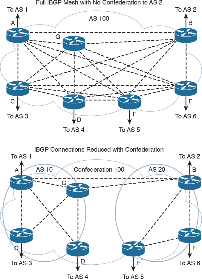
Routers A, B, and G are configured for eBGP between the sub-autonomous systems. You configure the bgp confederation identifier command on all routers The confederation identifier number is the same for all routers in the network. You use the bgp confederation peers command to identify the ASN of other sub-autonomous systems in the confederation. Because Routers A and G are in autonomous system 10, the peer confederation to Router B is autonomous system 20. Router B is in autonomous system 20, and its peer confederation to Routers A and G is autonomous system 10. Routers C and D are part of autonomous system 10 and peer with each other and with Routers A and G. Routers E and F are part of autonomous system 20 and peer with each other and with Router B.
BGP Administrative Distance
The Cisco IOS software assigns an administrative distance to eBGP and iBGP routes, as it does with other routing protocols. For the same prefix, the route with the lowest administrative distance is selected for inclusion in the IP forwarding table. For BGP, the administrative distances are
![]() eBGP routes: 20
eBGP routes: 20
![]() iBGP routes: 200
iBGP routes: 200
BGP Attributes, Weight, and the BGP Decision Process
The BGP protocol uses path attributes to select the best path to a destination. This subsection describes BGP attributes, the use of weight to influence path selection, and the BGP decision process.
BGP Path Attributes
BGP uses several attributes for the path-selection process. BGP uses path attributes to communicate routing policies. BGP path attributes include next hop, local preference, autonomous system path, origin, multi-exit discriminator (MED), Community, atomic aggregate, and aggregator. Of these, the autonomous system path is one of the most important attributes: It lists the number of autonomous system paths to reach a destination network.
BGP attributes can be categorized as well known or optional. Well-known attributes are recognized by all BGP implementations. Optional attributes do not have to be supported by the BGP process.
Well-known attributes can be further subcategorized as mandatory or discretionary. Mandatory attributes are always included in BGP update messages. Discretionary attributes might or might not be included in the BGP update message.
Optional attributes can be further subcategorized as transitive or nontransitive. Routers must advertise the route with transitive attributes to its peers even if it does not support the attribute locally. If the path attribute is nontransitive, the router does not have to advertise the route to its peers.
The following subsections cover each attribute category.
Next-Hop Attribute
The next-hop attribute is the IP address of the next IP hop that will be used to reach the destination. The next-hop attribute is a well-known mandatory attribute.
Local Preference Attribute
The local preference attribute indicates which path to use to exit the autonomous system. It is a well-known discretionary attribute used between iBGP peers and is not passed on to external BGP peers. In Cisco IOS Software, the default local preference is 100. The higher local preference is preferred.
The default local preference is configured on the BGP router with an external path; it then advertises its local preference to internal iBGP peers. Figure 11-14 shows an example of the local preference attribute where Routers B and C are configured with different local preference values. Router A and other iBGP routers then receive routes from both Router B and Router C. Between the two possible paths (shown with arrows), Router A prefers using Router C to route Internet packets because it has a higher local preference (400) than Router B (300).

Origin Attribute
Origin is a well-known mandatory attribute that defines the source of the path information. Do not confuse the origin with comparing whether the route is external (eBGP) or internal (iBGP). The origin attribute is received from the source BGP router. There are three types:
![]() IGP: Indicated by an i in the BGP table. Present when the route is learned by way of the network statement.
IGP: Indicated by an i in the BGP table. Present when the route is learned by way of the network statement.
![]() EGP: Indicated by an e in the BGP table. Learned from EGP.
EGP: Indicated by an e in the BGP table. Learned from EGP.
![]() Incomplete: Indicated by a question mark (?) in the BGP table. Learned from redistribution of the route.
Incomplete: Indicated by a question mark (?) in the BGP table. Learned from redistribution of the route.
In terms of choosing a route based on origin, BGP prefers routes that have been verified by an IGP over routes that have been learned from EGP peers, and BGP prefers routes learned from eBGP peers over incomplete paths.
Autonomous System Path Attribute
The autonomous system path is a well-known mandatory attribute that contains a list of ASNs in the path to the destination. Each autonomous system prepends its own ASN to the autonomous system path. The autonomous system path describes all the autonomous systems a packet would have to travel to reach the destination IP network. It is used to ensure that the path is loop free. When the autonomous system path attribute is used to select a path, the route with the fewest autonomous system hops is preferred. In the case of a tie, other attributes, such as MED, break the tie. Example 11-1 shows the autonomous system path for network 200.50.32.0/19. To reach the destination, a packet must pass autonomous systems 3561, 7004, and 7418. The command show ip bgp 200.50.32.0 displays the autonomous system path information.
Example 11-1 Autonomous System Path Attribute
Router# show ip bgp 200.50.32.0
BGP routing table entry for 200.50.32.0/19, version 93313535
Paths: (1 available, best #1)
Not advertised to any peer
3561 7004 7418
206.24.241.181 (metric 490201) from 165.117.1.219 (165.117.1.219)
Origin IGP, metric 4294967294, localpref 100, valid, internal, best
Community: 2548:182 2548:337 2548:666 3706:153
MED Attribute
The MED attribute, also known as a metric, tells an external BGP peer the preferred path into the autonomous system when multiple paths into the same autonomous system exist. In other words, MED influences which one of many paths a neighboring autonomous system uses to reach destinations within the autonomous system. It is an optional nontransitive attribute carried in eBGP updates. The MED attribute is not used with iBGP peers. The lowest MED value is preferred, and the default value is 0. Paths received with no MED are assigned a MED of 0. The MED is carried into an autonomous system but does not leave the autonomous system.
Consider the diagram shown in Figure 11-15. With all attributes considered equal, consider that Router C selects Router A as its best path into autonomous system 100 based on Router A’s lower router ID (RID). If Router A is configured with a MED of 200, that will make Router C select Router B as the best path to autonomous system 100. No additional configuration is required on Router B because the default MED is 0.

Community Attribute
Although it is not an attribute used in the routing-decision process, the community attribute groups routes and applies policies or decisions (accept, prefer) to those routes. It is a group of destinations that share some common property. The community attribute is an optional transitive attribute of variable length.
Atomic Aggregate and Aggregator Attributes
The atomic aggregate attribute informs BGP peers that the local router used a less specific (aggregated) route to a destination without using a more specific route.
The purpose of the attribute is to alert BGP speakers along the path that some information has been lost due to the route aggregation process and that the aggregate path might not be the best path to the destination. When some routes are aggregated by an aggregator, the aggregator does attach its Router-ID to the aggregated route in the AGGREGATOR_ID attribute, and it sets the ATOMIC_AGGREGATE attribute (or not) based on whether or not the AS_PATH information of the aggregated routes was preserved. The atomic aggregate attribute lets the BGP peers know that the BGP router used an aggregated route. A more-specific route must be in the advertising router’s BGP table before it propagates an aggregate route.
When the atomic aggregate attribute is used, the BGP speaker has the option to send the aggregator attribute. The aggregator attribute includes the ASN and the IP address of the router that originated the aggregated route. In Cisco routers, the IP address used is the RID of the router that performs the route aggregation. Atomic aggregate is a well-known discretionary attribute, and aggregator is an optional transitive attribute.
Weight
Weight is assigned locally on a router to specify a preferred path if multiple paths exist out of a router for a destination. Weights can be applied to individual routes or to all routes received from a peer. Weight is specific to Cisco routers and is not propagated to other routers. The weight value ranges from 0 to 65,535. Routes with a higher weight are preferred when multiple routes exist to a destination. Routes that are originated by the local router have a default weight of 32,768. The default weight for learned routes is 0.
You can use weight rather than local preference to influence the selected path to external BGP peers. The difference is that weight is configured locally and is not exchanged in BGP updates. On the other hand, the local preference attribute is exchanged between iBGP peers and is configured at the gateway router.
When the same destinations are advertised from both Router B and Router C, as shown in Figure 11-16, Router A prefers the routes from Router C over Router B because the routes received from Router C have a larger weight (600) locally assigned.

BGP Decision Process
By default, BGP selects only a single path to reach a specific destination (unless you specify maximum paths). The Cisco implementation of BGP uses a simple decision process. When the path is selected, BGP puts the selected path in its routing table and propagates the path to its neighbors.
To select the best path to a destination, Cisco routers running BGP use the following algorithm in the following order:
1. If the specified next hop is inaccessible, drop the path.
2. If the path is internal, and synchronization is enabled, and the path is not in the IGP, drop the path.
3. Prefer the path with the highest weight. (This step is Cisco specific, and weight is localized to the router.)
4. Prefer the path with the highest local preference. iBGP uses this path only to reach the preferred external BGP router.
5. Prefer the path that was locally originated via a network or aggregate BGP subcommand or through redistribution from an IGP. Local paths sourced by network or redistribute commands are preferred over local aggregates sourced by the aggregate-address command. (This step is Cisco specific.)
6. If no route was originated, prefer the route that has the shortest autonomous system path.
7. If all paths have the same autonomous system path length, prefer the path with the lowest origin type. Paths with an origin type of IGP (lower) are preferred over paths originated from an EGP such as BGP, and EGP origin is preferred over a route with an incomplete origin. (IGP < EGP < incomplete.)
8. If the origin codes are the same, prefer the path with the lowest MED attribute. An eBGP peer uses this attribute to select a best path to the autonomous system. This attribute is exchanged between autonomous systems. (This step is a tiebreaker, as described in the RFC that defines the BGP.)
9. If the paths have the same MED, prefer the external (eBGP) path over the internal (iBGP) path.
10. If the paths are still the same, prefer the path through the closest IGP neighbor (best IGP metric). (This step is a tiebreaker, as described in the RFC that defines the BGP.)
11. Prefer the path with the BGP neighbor with the lowest BGP router ID. (The RFC that defines the BGP describes the router ID.)
12. Prefer the path with the lowest neighbor IP address.
After BGP decides on a best path, it marks it with a > sign in the show ip bgp table and adds it to the IP routing table.
Note
Options for influencing outbound routing decisions include Weight, Local Preference, and AS Path Length. Options for influencing inbound routing decisions include AS Path Length, BGP Communities, and MED.
BGP Summary
The characteristics of BGP follow:
![]() BGP is an Exterior Gateway Protocol (EGP) used in routing in the Internet. It is an interdomain routing protocol.
BGP is an Exterior Gateway Protocol (EGP) used in routing in the Internet. It is an interdomain routing protocol.
![]() BGP is a path-vector routing protocol suited for strategic routing policies.
BGP is a path-vector routing protocol suited for strategic routing policies.
![]() It uses TCP port 179 to establish connections with neighbors.
It uses TCP port 179 to establish connections with neighbors.
![]() BGPv4 implements CIDR.
BGPv4 implements CIDR.
![]() eBGP is used for external neighbors. It is used between different autonomous systems.
eBGP is used for external neighbors. It is used between different autonomous systems.
![]() iBGP is used for internal neighbors. It is used within an autonomous system.
iBGP is used for internal neighbors. It is used within an autonomous system.
![]() BGP uses several attributes in the routing-decision algorithm.
BGP uses several attributes in the routing-decision algorithm.
![]() It uses confederations and route reflectors to reduce BGP peering overhead.
It uses confederations and route reflectors to reduce BGP peering overhead.
![]() The MED (metric) attribute is used between autonomous systems to influence inbound traffic.
The MED (metric) attribute is used between autonomous systems to influence inbound traffic.
![]() Weight is used to influence the path of outbound traffic from a single router, configured locally.
Weight is used to influence the path of outbound traffic from a single router, configured locally.
Route Manipulation
This section covers policy-based routing (PBR), route summarization, route filtering, and route redistribution. You can use PBR to modify the next hop of packets from what is selected by the routing protocol. PBR is useful when the traffic engineering of paths is required. Routes are summarized to reduce the size of routing tables and at network boundaries. Redistribution between routing protocols is required to inject route information from one routing protocol to another. Route filtering is used to control network addresses that get redistributed or to control access to certain parts of the network. The CCDA must understand the issues with the redistribution of routes.
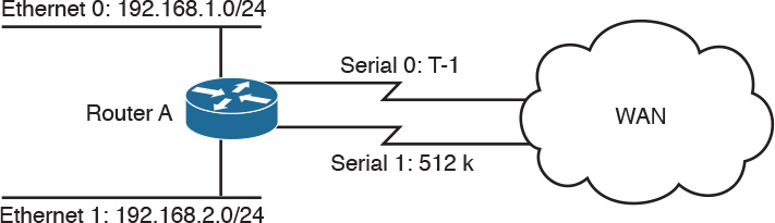
PBR
You can use PBR to modify the next-hop address of packets or to mark packets to receive differential service. Routing is based on destination addresses; routers look at the routing table to determine the next-hop IP address based on a destination lookup. PBR is commonly used to modify the next-hop IP address based on the source address. You can also use PBR to mark the IP precedence bits in outbound IP packets so that you can apply QoS policies. In Figure 11-17, Router A exchanges routing updates with routers in the WAN. The routing protocol might select Serial 0 as the preferred path for all traffic because of the higher bandwidth. The company might have business-critical systems that use the T1 but does not want systems on Ethernet 1 to affect WAN performance. You can configure PBR on Router A to force traffic from Ethernet 1 out on Serial 1.
Route Summarization
Large networks can grow quickly, from 500 routes to 1000, to 2000, and higher. Network IP addresses should be allocated to allow for route summarization. Route summarization reduces the amount of route traffic on the network, unnecessary route computation, and the perceived complexity of the network. Route summarization also allows the network to scale as a company grows.
The recommended location for route summarization is to summarize at the distribution layer of the network topology. Figure 11-18 shows a hierarchical network. It has a network core, regional distribution routers, and access routes for sites.
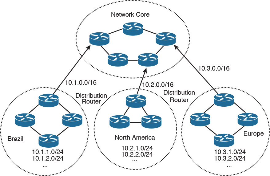
All routes in Brazil are summarized with a single 10.1.0.0/16 route. The North American and European routes are also summarized with 10.2.0.0/16 and 10.3.0.0/16, respectively. Routers in Europe need to know only the summarized route to get to Brazil and North America, and vice versa. Again, a design best practice is to summarize at the distribution toward the core. The core needs to know only the summarized route of the regional areas.
You can also use summarization to aggregate four contiguous Class C networks at the /22 bit level. For example, networks 200.1.100.0, 200.1.101.0, 200.1.102.0, and 200.1.103.0 share common bits, as shown in Table 11-7. The resulting network is 200.1.100.0/22, which you can use for a 1000-node network.

It is important for an Internet network designer to assign IP networks in a manner that permits summarization. It is preferred that a neighboring router receive one summarized route, rather than 8, 16, 32, or more routes, depending on the level of summarization. This setup reduces the size of the routing tables in the network.
For route summarization to work, the multiple IP addresses must share the same leftmost bits, and routers must base their routing decisions on the IP address and prefix length. Figure 11-19 shows another example of route summarization. All the edge routers send network information to their upstream routers. Router E summarizes its two LAN networks by sending 192.168.16.0/23 to Router A. Router F summarizes its two LAN networks by sending 192.168.18.0/23. Router B summarizes the networks it receives from Routers C and D. Routers B, E, and F send their routes to Router A. Router A sends a single route (192.168.16.0/21) to its upstream router, instead of sending eight routes. This process reduces the number of networks that upstream routers need to include in routing updates.

Notice in Table 11-8 that all the Class C networks share a bit boundary with 21 common bits. The networks are different on the 22nd bit and thus cannot be summarized beyond the 21st bit. All these networks are summarized with 192.168.16.0/21.

To summarize, the recommended practices regarding summarization include the following:
![]() Implement summarization at WAN connectivity and remote-access points toward the network core, to reduce the routing table size.
Implement summarization at WAN connectivity and remote-access points toward the network core, to reduce the routing table size.
![]() Summarize at the distribution layer for all network interfaces that point to the network core.
Summarize at the distribution layer for all network interfaces that point to the network core.
![]() Implement passive interfaces on access layer interfaces so that neighbor adjacencies are not established through the access layer. A more-specific route might be created, which would be taken over a summarized route.
Implement passive interfaces on access layer interfaces so that neighbor adjacencies are not established through the access layer. A more-specific route might be created, which would be taken over a summarized route.
Route Redistribution
Route redistribution is an exchange of routes between routing protocols (for example, between EIGRP and OSPF). You configure the redistribution of routing protocols on routers that reside at the service provider edge of the network or an autonomous system boundary within the internal network. These routers exchange routes with other autonomous systems. Redistribution is also done on routers that run more than one routing protocol. Here are some reasons to do redistribution:
![]() Migration from an older routing protocol to a new routing protocol.
Migration from an older routing protocol to a new routing protocol.
![]() Mixed-vendor environment in which Cisco routers might be using EIGRP and other vendor routers might be using OSPF.
Mixed-vendor environment in which Cisco routers might be using EIGRP and other vendor routers might be using OSPF.
![]() Different administrative domain between company departments using different routing protocols.
Different administrative domain between company departments using different routing protocols.
![]() Mergers and acquisitions in which the networks initially need to communicate. In this scenario, two different EIGRP processes might exist.
Mergers and acquisitions in which the networks initially need to communicate. In this scenario, two different EIGRP processes might exist.
Routes can be learned from different sources. The first is a static route that is configured when not peering with the AS-external router. Another source is a different routing protocol where you might be running EIGRP and the other network uses OSPF. Another common example is when peering with an ISP, the enterprise is commonly using OSPF and your Internet routers peer with the ISP router using BGP.
Figure 11-20 shows an example of the exchange of routes between two autonomous systems. Routes from autonomous system 100 are redistributed into BGP on Router A. Routes from autonomous system 200 are redistributed into BGP on Router B. Then, Routers A and B exchange BGP routes. Router A and Router B also implement filters to redistribute only the desired networks.

A company might also acquire another company that might be running another routing protocol. Figure 11-21 shows a network that has both OSPF and EIGRP routing protocols. Routers A and B perform redistribution between OSPF and EIGRP. Both routers must filter routes from OSPF before redistributing them into EIGRP and filter routes from EIGRP before redistributing them into OSPF. This setup prevents route feedback.

Route feedback occurs when a routing protocol learns routes from another routing protocol and then announces the routes to the other routing protocol. In Figure 11-21, OSPF should not advertise the routes it learned from EIGRP on Router A back to EIGRP on Router B. And EIGRP should not announce the routes it learned from OSPF on Router B back to OSPF on Router A.
You can use access lists, distribution lists, and route maps when redistributing routes. You can use these methods to specify (select) routes for redistribution, to set metrics, or to set other policies for the routes. They are used to prevent loops in the redistribution. They are also used to control routes’ redistribution direction. Redistribution can be accomplished by two methods:
![]() One-way redistribution
One-way redistribution
In two-way redistribution, routing information is exchanged between both routing protocols. No static routes are used in this exchange. Route filters are used to prevent routing loops. Routing loops can be caused by one route protocol redistributing routes that were learned from a second route protocol back to that second routing protocol.
One-way redistribution only allows redistribution from one routing protocol to another. Normally, it is used in conjunction with a default or static route at the edge of a network. Figure 11-22 shows an example of one-way redistribution. The routing information from the WAN routes is redistributed into the campus, but campus routes are not redistributed out to the WAN. The WAN routers use a default route to get back to the campus.
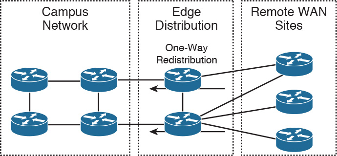
Other locations for one-way redistribution are from building access networks, BGP routes or static routes into the IGP, and from VPN static routes into the IGP.
Default Metric
You should configure the metric of the redistributed routes to a metric other than 0. You can configure the metric in the redistribution command or configure a default seed metric. You can also use the command in OSPF. IS-IS does not use the default-metric command. The default-metric command is used to specify the seed metric that is used if one is not specified during redistribution The default-metric command has the following syntax for EIGRP:
default-metric bandwidth delay reliability load mtu
OSPF Redistribution
This subsection reviews a few things you need to remember when designing a network that will redistribute with OSPF.
When redistributing routes into OSPF, use the subnets keyword to permit subnetted routes to be received. If you do not use it, only the major network route is redistributed, without any subnetworks. In other words, OSPF performs automatic summarization to IP classful network values. Also, unlike EIGRP and RIPv2, OSPF does not need a metric to be specified during redistribution; neither does it need a seed metric to be specified because it uses a default metric for redistributed routes.
By default, redistributed routes are classified as external Type 2 (E2) in OSPF. You can use the metric-type keyword to change the external route to an external Type 1 (E1). The network design can take into account the after-redistribution cost (Type 2) or the after-redistribution cost plus the path’s cost (Type 1).
In Figure 11-23, Router B is configured to perform mutual redistribution between EIGRP 100 and OSPF process ID 50. In this example, you can use route maps and access lists to prevent routing loops. The route maps permit or deny the networks that are listed in the access lists. The subnets keyword redistributes every subnet in EIGRP into OSPF. This book does not cover exact configurations.

Route Filtering
Filtering of routes can occur on either a redistribution point or in the routing domain to prevent some parts of the network from accessing other sections of the network. Route filtering is used to filter routes at the redistribution of BGP into IGPs such as OSPF, EIGRP, or IS-IS.
Filtering at a redistribution point provides the following benefits:
![]() Avoids routing loops
Avoids routing loops
![]() Avoids suboptimal routing
Avoids suboptimal routing
![]() Prevents certain routes from entering the domain
Prevents certain routes from entering the domain
Transit Traffic
With BGP, you should be attentive to not configure your network as a transit network between autonomous systems. This commonly occurs when you connect your enterprise network to two ISPs in a multihomed BGP configuration. When BGP routes get exchanged with multiple Internet service providers (ISPs), route filtering is used to prevent advertisement of private addresses and addresses that are out of scope of the domain. The recommendation is to filter routes so that only the enterprise prefixes are advertised to the ISPs, as illustrated in Figure 11-24.

Routing Protocols on the Hierarchical Network Infrastructure
The selected routing protocol should be used based on the network design goals and the network module being used. As shown in Figure 11-25, high-speed routing is recommended for the network core and distribution layers. These routing protocols react fast to network changes. It is a best practice that the same routing protocol be used in the three layers (core, distribution, access) of the enterprise network.

The enterprise edge connects the campus network with external connectivity, including WAN, Internet, VPN, and remote-access modules. Routing protocols in the enterprise edge may be EIGRP, OSPF, BGP, and static routes. Specifically in the Internet module you will find BGP/static routes.
Table 11-9 shows a summary of the recommended routing protocols in the network infrastructure.

IP Multicast Review
With multicast, packets are sent to a multicast group, which is identified with an IP multicast address. Multicast supports the transmission of IP packets from one source to multiple hosts. Packets with unicast addresses are sent to one device, and broadcast addresses are sent to all hosts; packets with multicast addresses are sent to a group of hosts.
Multicast Addresses
Multicast addressing uses Class D addresses from the IPv4 protocol. Class D addresses range from 224.0.0.0 to 239.255.255.255. IANA manages multicast addresses.
Routing protocols (RIPv2, EIGRP, and OSPF) use multicast addresses to speak to their neighbors. For example, OSPF routers use 224.0.0.6 to speak to the designated router (DR) in a multiaccess network. Class D multicast addresses range from 224.0.0.0 to 239.255.255.255. Multicast addresses in the range of 224.0.0.1 to 224.255.255.255 are reserved for special addresses or network protocols on a multiaccess link. RFC 2365 reserves multicast addresses in the range of 239.192.000.000 to 239.251.255.255 for organization-local scope. Similarly, 239.252.000.000 to 239.252.255.255, 239.254.000.000 to 239.254.255.255, and 239.255.000.000 to 239.255.255.255 are reserved for site-local scope.
Table 11-10 lists some well-known and multicast address blocks.

Layer 3 to Layer 2 Mapping
Multicast-aware Ethernet, Token Ring, and Fiber Distributed Data Interface (FDDI) network interface cards use the reserved IEEE 802 address 0100.5e00 for multicast addresses at the MAC layer. This includes Fast Ethernet and Gigabit Ethernet. Notice that for the address, the high-order byte 0x01 has the low-order bit set to 1. This bit is the Individual/Group (I/G) bit. It signifies whether the address is an individual address (0) or a group address (1). Hence, for multicast addresses, this bit is set to 1.
Ethernet interfaces map the lower 23 bits of the IP multicast address to the lower 23 bits of the MAC address 0100.5e00.0000. As an example, the IP multicast address 224.0.0.2 is mapped to the MAC layer as 0100.5e00.0002. Figure 11-26 shows another example looking at the bits of multicast IP 239.192.44.56. The IP address in hexadecimal is EF:C0:2C:38. The lower 23 bits get mapped into the lower 23 bits of the base multicast MAC to produce the multicast MAC address 01:00:5E:40:2C:38.

IGMP
Internet Group Management Protocol is the protocol used in multicast implementations between the end hosts and the local router. RFC 2236 describes IGMP Version 2 (IGMPv2). RFC 3376 describes IGMP Version 3 (IGMPv3). RFC 1112 describes the first version of IGMP.
IP hosts use IGMP to report their multicast group memberships to routers. IGMP messages use IP protocol number 2. IGMP messages are limited to the local interface and are not routed.
IGMPv1
The first RFC describing IGMP (RFC 1112), written in 1989, describes the host extensions for IP multicasting. IGMPv1 provides simple message types for communication between hosts and routers. These messages are
![]() Membership query: Sent by the router to check whether a host wants to join a multicast group
Membership query: Sent by the router to check whether a host wants to join a multicast group
![]() Membership report: Sent by the host to join a multicast group in the segment
Membership report: Sent by the host to join a multicast group in the segment
The problem with IGMPv1 is the latency involved for a host to leave a group. With IGMPv1, the router sends membership queries periodically; a host must wait for the membership query message to leave a group. The query interval is 60 seconds, and it takes three query intervals (3 minutes) for a host to leave the group.
IGMPv2
IGMPv2 improves on IGMPv1 by allowing faster termination or leaving of multicast groups.
IGMPv2 has three message types, plus one for backward compatibility:
![]() Membership query: Sent by the router to check whether a host wants to join a group.
Membership query: Sent by the router to check whether a host wants to join a group.
![]() Version 2 membership report: A message sent to the group address with the multicast group members (IP addresses). It is sent by hosts to join and remain in multicast groups on the segment.
Version 2 membership report: A message sent to the group address with the multicast group members (IP addresses). It is sent by hosts to join and remain in multicast groups on the segment.
![]() Version 2 leave group: Sent by the hosts to indicate that a host will leave a group; it is sent to destination 224.0.0.2. After the host sends the leave group message, the router responds with a group-specific query.
Version 2 leave group: Sent by the hosts to indicate that a host will leave a group; it is sent to destination 224.0.0.2. After the host sends the leave group message, the router responds with a group-specific query.
![]() Version 1 membership report: For backward compatibility with IGMPv1 hosts.
Version 1 membership report: For backward compatibility with IGMPv1 hosts.
You enable IGMP on an interface when you configure a multicast routing protocol, such as PIM. You can configure the interface for IGMPv1, IGMPv2, or IGMPv3.
IGMPv3
IGMPv3 provides the extensions required to support source-specific multicast (SSM). It is designed to be backward compatible with both earlier versions of IGMP.
IGMPv3 has two message types, plus three for backward compatibility:
![]() Membership query: Sent by the router to check that a host wants to join a group.
Membership query: Sent by the router to check that a host wants to join a group.
![]() Version 3 membership report: A message sent to the group address with the multicast group members (IP addresses). It is sent by hosts to request and remain in multicast groups on the segment.
Version 3 membership report: A message sent to the group address with the multicast group members (IP addresses). It is sent by hosts to request and remain in multicast groups on the segment.
![]() Version 2 membership report: A message sent to the group address with the multicast group members (IP addresses). It is sent by hosts to request and remain in multicast groups on the segment. This message is used for backward compatibility with IGMPv2 hosts.
Version 2 membership report: A message sent to the group address with the multicast group members (IP addresses). It is sent by hosts to request and remain in multicast groups on the segment. This message is used for backward compatibility with IGMPv2 hosts.
![]() Version 2 leave group: Sent by the hosts to indicate that a host will leave a group, to destination 224.0.0.2. The message is sent without having to wait for the IGMPv2 membership report message. This message is used for backward compatibility with IGMPv2 hosts.
Version 2 leave group: Sent by the hosts to indicate that a host will leave a group, to destination 224.0.0.2. The message is sent without having to wait for the IGMPv2 membership report message. This message is used for backward compatibility with IGMPv2 hosts.
![]() Version 1 membership report: A message used for backward compatibility with IGMPv1 hosts.
Version 1 membership report: A message used for backward compatibility with IGMPv1 hosts.
You enable IGMP on an interface when you enable a multicast routing protocol, such as PIM. You can configure the interface for IGMPv1, IGMPv2, or IGMPv3.
CGMP
CGMP is a Cisco proprietary protocol implemented to control multicast traffic at Layer 2. Because a Layer 2 switch is unaware of Layer 3 IGMP messages, it cannot keep multicast packets from being sent to all ports.
As shown in Figure 11-27, with CGMP the LAN switch can speak with the IGMP router to find out the MAC addresses of the hosts that want to receive the multicast packets. With CGMP, switches distribute multicast sessions only to the switch ports that have group members.

When a router receives an IGMP report, it processes the report and then sends a CGMP message to the switch. The switch can then forward the multicast messages to the port with the host receiving multicast traffic. CGMP fast-leave processing allows the switch to detect IGMP Version 2 leave messages sent by hosts on any of the switch ports. When a host sends the IGMPv2 leave message, the switch can then disable multicasting for the port.
CGMP is no longer used and is not a CCDA topic. IGMP snooping is the standards-based protocol used in today’s networks.
IGMP Snooping
IGMP snooping is a standards-based method for switches to control multicast traffic at Layer 2. It has replaced CGMP. It listens to IGMP messages between the hosts and routers. If a host sends an IGMP query message to the router, the switch adds the host to the multicast group and permits that port to receive multicast traffic. The port is removed from multicast traffic if the host sends an IGMP leave message to the router. The disadvantage of IGMP snooping is that it has to process every IGMP control message, which can impact the CPU utilization of the switch.
Sparse Versus Dense Multicast
IP multicast traffic for a particular (source, destination group) multicast pair is transmitted from the source to the receivers using a spanning tree from the source that connects all the hosts in the group. Multicast destinations are represented in the following form: (S,G) or (*,G). Any multicast transmission has a Class D multicast group address, G. A multicast group can have more than one source, and each such source will also have a “regular” (Class A, B or C, or CIDR) Internet address, S. The notation (*,G) means every possible source for the given group G, while (S,G) means a particular source, at the particular Internet address S, in the group G.
Each destination host registers itself as a member of interesting multicast groups through the use of IGMP. Routers keep track of these groups dynamically and build distribution trees that chart paths from each sender to all receivers. IP multicast routing protocols follow two approaches.
The first approach assumes that the multicast group members are densely distributed throughout the network (many of the subnets contain at least one group member), that all devices want to receive multicast traffic, and that bandwidth is plentiful. The approach with dense multicast routing protocols is to flood the traffic throughout the network and then, at the request of receiving routers, stop the flow of traffic on branches of the network that have no members of the multicast group. Multicast routing protocols that follow this technique of flooding the network include DVMRP, Multicast Open Shortest Path First (MOSPF), and Protocol-Independent Multicast-Dense Mode (PIM-DM).
The second approach to multicast routing assumes that multicast group members are sparsely distributed throughout the network, it assumes that not all devices want to receive multicast traffic, and that bandwidth is not necessarily widely available. Sparse mode does not imply that the group has few members, just that they are widely dispersed. The approach with sparse multicast routing protocols is to not send traffic until it is requested by the receiving routers or hosts. Multicast routing protocols of this type are Core-Based Trees (CBT) and Protocol-Independent Multicast-Sparse Mode (PIM-SM). CBT is not widely deployed and is not discussed in this book.
Multicast Source and Shared Trees
Multicast distribution trees control the path that multicast packets take to the destination hosts. The two types of distribution trees are source and shared. With source trees, the tree roots from the source of the multicast group and then expands throughout the network in spanning-tree fashion to the destination hosts. Source trees are also called shortest-path trees (SPTs) because they create paths without having to go through a rendezvous point (RP). The drawback is that all routers through the path must use memory resources to maintain a list of all multicast groups. PIM-DM uses a source-based tree.
Shared trees create the distribution tree’s root somewhere between the network’s source and receivers. The root is called the RP. The tree is created from the RP in spanning-tree fashion with no loops. The advantage of shared trees is that they reduce the memory requirements of routers in the multicast network. The drawback is that initially the multicast packets might not take the best paths to the receivers because they need to pass through the RP. After the data stream begins to flow from sender to RP to receiver, the routers in the path optimize the path automatically to remove any unnecessary hops. The RP function consumes significant memory on the assigned router. PIM-SM uses an RP.
PIM
PIM comes in two flavors: sparse mode (PIM-SM) and dense mode (PIM-DM). The first uses shared trees and RPs to reach widely dispersed group members with reasonable protocol bandwidth efficiency. The second uses source trees and reverse path forwarding (RPF) to reach relatively close group members with reasonable processor and memory efficiency in the network devices of the distribution trees.
With RPF, received multicast packets are forwarded out all other interfaces, allowing the data stream to reach all segments. If no hosts are members of a multicast group on any of the router’s attached or downstream subnets, the router sends a prune message up the distribution tree (the reverse path) to tell the upstream router not to send packets for the multicast group. So, the analogy for PIM-DM is the push method for sending junk mail, and the intermediate router must tell upstream devices to stop sending it.
PIM-SM
PIM-SM is defined in RFC 2362. PIM-SM assumes that no hosts want to receive multicast traffic unless specifically requested. The RP gathers the information from senders and makes the information available to receivers. Routers with receivers have to register with the RP. The end-host systems request multicast group membership using IGMP with their local routers. The routers serving the end systems then register as traffic receivers with the RPs for the specified group in the multicast network.
Joining PIM-SM
With PIM-SM, DRs on end segments receive IGMP query messages from hosts wanting to join a multicast group. The router checks whether it is already receiving the group for another interface. If it is receiving the group, the router adds the new interface to the table and sends membership reports periodically on the new interface.
If the multicast group is not in the multicast table, the router adds the interface to the multicast table and sends a join message to the RP with multicast address 224.0.0.13 (all PIM routers) requesting the multicast group.
Pruning PIM-SM
When a PIM-SM does not have any more multicast receiving hosts or receiving routers out any of its interfaces, it sends a prune message to the RP. The prune message includes the group to be pruned or removed.
PIM DR
A designated router is selected in multiaccess segments running PIM. The PIM DR is responsible for sending join, prune, and register messages to the RP. The PIM router with the highest IP address is selected as the DR.
Auto-RP
Another way to configure the RP for the network is to have the RP announce its services to the PIM network. This process is called auto-RP. Candidate RPs send their announcements to RP mapping agents with multicast address 224.0.1.39 (cisco-rp-announce). RP mapping agents are also configured. In smaller networks, the RP can be the mapping agent. The 224.0.1.40 address used in AUTO-RP-DISCOVERY is the destination address for messages from the RP mapping agent to discover candidates. Configured RP mapping agents listen to the announcements. The RP mapping agent then selects the RP for a group based on the highest IP address of all the candidate RPs. The RP mapping agents then send RP-discovery messages to the rest of the PIM-SM routers in the internetwork with the selected RP-to-group mappings.
PIMv2 Bootstrap Router
Instead of using auto-RP, you can configure a PIMv2 bootstrap router (BSR) to automatically select an RP for the network. The RFC for PIM Version 2, RFC 2362, describes BSR. With BSR, you configure BSR candidates (C-BSR) with priorities from 0 to 255 and a BSR address. C-BSRs exchange bootstrap messages. Bootstrap messages are sent to multicast IP 224.0.0.13 (all PIM routers). If a C-BSR receives a bootstrap message, it compares it with its own. The largest priority C-BSR is selected as the BSR.
After the BSR is selected for the network, it collects a list of candidate RPs. The BSR selects RP-to-group mappings, which is called the RP set, and distributes the selected RPs using bootstrap messages sent to 224.0.0.13 (all PIM routers).
DVMRP
RFC 1075 describes DVMRP. It is the primary multicast routing protocol used in the multicast backbone (MBONE). The MBONE is used in the research community.
DVMRP operates in dense mode using RPF by having routers send a copy of a multicast packet out all paths. Routers that receive the multicast packets then send prune messages back to their upstream neighbor router to stop a data stream if no downstream receivers of the multicast group exist (either receiving routers or hosts on connected segments). DVMRP implements its own unicast routing protocol, similar to RIP, based on hop counts. DVMRP has a 32 hop-count limit. DVMRP does not scale suboptimally. Cisco’s support of DVMRP is partial; DVMRP networks are usually implemented on UNIX machines running the mrouted process. A DVMRP tunnel is typically used to connect to the MBONE DVMRP network.
IPv6 Multicast Addresses
IPv6 retains the use and function of multicast addresses as a major address class. IPv6 prefix FF00::/8 is allocated for all IPv6 multicast addresses. IPv6 multicast addresses are described in RFC 2373. EIGRP for IPv6, OSPFv3, and RIPng routing protocols use multicast addresses to communicate between router neighbors.
The format of the IPv6 multicast address is described in Chapter 9, “Internet Protocol Version 6 Design.” The common multicast addresses are repeated in Table 11-11.

References and Recommended Readings
Bruno, A. CCIE Routing and Switching Exam Certification Guide. Indianapolis: Cisco Press, 2002.
RFC 2740: OSPF for IPv6, available from www.ietf.org/rfc.
RFC 1587: The OSPF NSSA Option, www.ietf.org/rfc.
Martey, A. IS-IS Network Design Solutions. Indianapolis: Cisco Press, 2002.
RFC 1584: Multicast Extensions to OSPF, www.ietf.org/rfc.
RFC 2328: OSPF Version 2, www.ietf.org/rfc.
RFC 1142: OSI IS-IS Intra-domain Routing Protocol, www.ietf.org/rfc.
Border Gateway Protocol, www.cisco.com/univercd/cc/td/doc/cisintwk/ito_doc/bgp.htm.
RFC 1997: BGP Communities Attribute, www.ietf.org/rfc.
RFC 1112: Host Extensions for IP Multicasting, www.ietf.org/rfc.
Doyle, J. and J. Carroll. Routing TCP/IP, Volume I, Second Edition. Indianapolis: Cisco Press, 2005.
Doyle, J. and J. Carroll. Routing TCP/IP, Volume II. Indianapolis: Cisco Press, 2001.
RFC 2362: Protocol Independent Multicast-Sparse Mode (PIM-SM): Protocol Specification (experimental), www.ietf.org/rfc.
RFC 2236: Internet Group Management Protocol, Version 2, www.ietf.org/rfc.
RFC 1519: Classless Inter-Domain Routing (CIDR): An Address Assignment and Aggregation Strategy, www.ietf.org/rfc.
Halabi, S. Internet Routing Architectures. Indianapolis: Cisco Press, 2000.
“IP Multicast Technology Overview” (white paper), http://www.cisco.com/c/en/us/td/docs/ios/solutions_docs/ip_multicast/White_papers/mcst_ovr.html.
RFC 2365: Administratively Scoped IP Multicast, www.ietf.org/rfc.
A Border Gateway Protocol 4 (BGP-4), www.ietf.org/rfc.
RFC 1075: Distance Vector Multicast Routing Protocol, www.ietf.org/rfc.
Williamson, B. Developing IP Multicast Networks. Indianapolis: Cisco Press, 1999.
RFC 2858: Multiprotocol Extensions for BGP-4, www.ietf.org/rfc.
RFC 4271: A Border Gateway Protocol 4 (BGP-4), www.ietf.org/rfc.
RFC 5340: OSPF for IPv6, www.ietf.org/rfc.
RFC 5838: Support of Address Families in OSPFv3, www.ietf.org/rfc.
RFC 6969: OSPFv3 Instance ID Registry Update, www.ietf.org/rfc.
BGP Attributes: Atomic Aggregate Attribute, www.networkers-online.com/blog/2010/12/bgp-attributes-atomic-aggergate-atribute/.
Exam Preparation Tasks
Review All Key Topics
Review the most important topics in the chapter, noted with the Key Topic icon in the outer margin of the page. Table 11-12 lists a reference of these key topics and the page numbers on which each is found.

Complete Tables and Lists from Memory
Print a copy of Appendix D, “Memory Tables” (found on the book website), or at least the section for this chapter, and complete the tables and lists from memory. Appendix E, “Memory Tables Answer Key,” also on the website, includes completed tables and lists to check your work.
Define Key Terms
Define the following key terms from this chapter, and check your answers in the glossary:
Q&A
The answers to these questions appear in Appendix A, “Answers to the ‘Do I Know This Already?’ Quizzes and Q&A Questions.” For more practice with exam format questions, use the exam engine on the CD.
1. True or false: A router needs to have all its interfaces in Area 0 to be considered an OSPF backbone router.
2. True or false: OSPF and IS-IS use a designated router in multiaccess networks.
3. Which multicast addresses do OSPFv2 routers use?
4. Which multicast addresses are used by OSPFv3 routers?
5. What is the Cisco administrative distance of OSPF?
6. Which OSPFv2 router type generates the OSPF Type 3 LSA?
7. Which OSPFv2 router type generates the OSPF Type 2 LSA?
8. What is included in an OSPFv2 router LSA?
9. True or false: The router with the lowest priority is selected as the OSPF DR.
10. True or false: You use iBGP to exchange routes between different autonomous systems.
11. True or false: BGP Version 4 does not include support for CIDR, only OSPF and EIGRP do.
12. True or false: eBGP and iBGP redistribute automatically on a router if the BGP peers are configured with the same autonomous system number.
13. eBGP routes have an administrative distance of ____, and iBGP routes have an administrative distance of ____.
14. True or false: IGMP snooping and CGMP are methods to reduce the multicast traffic at Layer 2.
15. True or false: PIM has a hop-count limit of 32.
16. True or false: PIM-SM routers use the multicast 224.0.0.13 address to request a multicast group to the RP.
17. True or false: Autonomous system path is the only attribute BGP uses to determine the best path to the destination.
18. List three IP routing protocols that use multicast addresses to communicate with their neighbors.
19. What IPv6 multicast address does EIGRP use for IPv6?
20. Match the routing protocol with the description:
i. EIGRP
ii. OSPFv2
iii. RIPv2
iv. BGP
a. Distance-vector protocol used in the edge of the network
b. IETF link-state protocol used in the network core
c. Hybrid protocol used in the network core
d. Path-vector protocol
21. What is the default OSPF cost for a Fast Ethernet interface?
22. Which routing protocol do you use in the core of a large enterprise network that supports VLSMs for a network with a mix of Cisco and non-Cisco routers?
23. What is the benefit of designing for stub areas?
24. What constraint does the OSPF network design have for traffic traveling between areas?
25. How is OSPFv3 identified as the upper-layer protocol in IPv6?
26. Which routing protocols are recommended for large enterprise networks?
a. RIPv2
b. OSPFv2
c. EIGRP
d. IS-IS
e. A and B
f. B and C
g. B and D
h. A, B, C, and D
27. What OSPFv3 LSA has an LS type of 0x0008?
a. Router LSA
b. Inter-area-router LSA
c. Link LSA
d. Intra-area-prefix LSA
28. Which routing protocol does not support VLSMs?
a. RIPv1
b. OSPFv2
c. EIGRP
d. RIPv2
e. B and C
f. B, C, and D
29. Which routing protocols have fast convergence for IPv4 networks?
a. BGP
b. OSPFv2
c. EIGRP
d. RIPv2
e. B and C
f. B, C, and D
g. A, B, and C
30. Which routing protocols have fast convergence for IPv6 networks?
a. RIPng
b. OSPFv3
c. EIGRP for IPv6
d. RIPv2
e. MP-BGP
f. B and C
g. B, C, and D
h. B, C, and E
31. A retail chain has about 800 stores that connect to the headquarters and a backup location. The company wants to limit the amount of routing traffic used on the WAN links. What routing protocol(s) is/are recommended?
a. RIPv1
b. RIPv2
c. OSPFv2
d. EIGRP
e. IS-IS
f. BGP
g. B, C, and D
h. C and D
i. C, D, and E
32. Which of the following statements is correct?
a. OSPFv3 provides changes to OSPFv2 for use in IPv4 networks.
b. OSPFv3 provides changes to OSPFv2 for use in IPv6 networks.
c. OSPFv3 provides changes to OSPFv2 for use in IPv6 and IPv4 networks.
d. OSPFng provides changes to OSPFv2 for use in IPv6 networks.
Use Figure 11-28 to answer the following question.

33. If OSPF is enabled on all routers with the default metrics unchanged, what path is taken?
a. Path 1
b. Path 2
c. Unequal load balance with Path 1 and Path 2
d. Equal load balance with Path 1 and Path 2
Use Figure 11-29 to answer the following question.
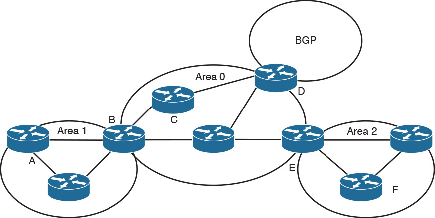
34. Identify the OSPF router types shown in Figure 11-29.
Router A = _______
Router B = _______
Router C = _______
Router D = _______
Router E = _______
Router F = _______
35. Match the IP multicast address with its description.
i. 224.0.0.1
ii. 224.0.0.2
iii. 224.0.0.5
iv. 224.0.0.10
a. All OSPF routers
b. All routers
c. EIGRP routers
d. All hosts
36. Match the BGP attribute with its description.
i. Local preference
ii. MED
iii. Autonomous system path
iv. Next hop
b. Indicates the path used to exit the autonomous system
c. Tells external BGP peers the preferred path into the autonomous system
d. List of ASNs
37. Which Cisco feature can you use instead of local preference to influence the selected path to external BGP routers?
38. What is the purpose of route reflectors?
39. When BGP confederations are used, which number do external peers see?
40. With ____________, all routers peer with each other within the private autonomous system. With __________, client routers peer only with the reflector.
41. Which of the following shows the correct order that BGP uses to select a best path?
a. Origin, lowest IP, autonomous system path, weight, local preference, MED
b. Weight, local preference, autonomous system path, origin, MED, lowest IP
c. Lowest IP, autonomous system path, origin, weight, MED, local preference
d. Weight, origin, local preference, autonomous system path, MED, lowest IP
42. What feature did BGPv4 implement to provide forwarding of packets based on IP prefixes?
43. What route should be used to summarize the following networks?
10.150.80.0/23, 10.150.82.0/24, 10.150.83.0/24, 10.150.84.0/22
a. 10.150.80.0/23, 10.150.82.0/23, and 10.150.84.0/22
b. 10.150.80.0/22 and 10.150.84/22
c. 10.150.80.0/21
d. 10.150.80.0/20
44. Match the IPv6 multicast address with its description.
i. FF02::1
ii. FF02::2
iii. FF02::5
iv. FF02::9
v. FF02::A
a. OSPFv3 routers
b. RIPng routers
c. All routers
d. EIGRP routers
e. All nodes
45. Route summarization and redistribution occur in which layer of the hierarchical model?
a. Building access
b. Distribution
c. Core
d. Server access
46. Which of the following best describes route summarization?
a. Grouping contiguous addresses to advertise a large Class A network
b. Grouping noncontiguous addresses to advertise a larger network
c. Grouping contiguous addresses to advertise a larger network
d. Grouping Internet addresses
47. Which standards-based routing protocol converges most quickly?
a. RIPv2
b. OSPF
c. EIGRP
d. BGP
48. Which routing protocol(s) do not require subinterfaces when operating over nonbroadcast multiaccess point-to-multipoint networks?
a. RIP
b. OSPF
c. EIGRP
d. BGP
e. IS-IS
49. Which link-state routing protocols support IPv6 routing?
a. RIP
b. OSPF
c. EIGRP
d. BGP
e. IS-IS
50. Which OSPF area allows redistribution of external routers while preventing propagation of Type 5 LSAs?
a. Area 0
b. Stub area
c. Not so stubby area
d. ABR
e. Area 1 over a Virtual Link
51. Which protocol is commonly used to connect to an ISP?
a. RIPv2
b. OSPF
c. EIGRP
d. BGP
52. Which of the following statements are true regarding OSPF? (Choose two.)
a. ABRs require manual configuration for summarization.
b. ABRs automatically summarize.
c. External routes are injected into the autonomous system via the ABR.
d. External routes are injected into the autonomous system via the ASBR.
53. Which routing protocol provides multivendor support with high scalability and fast convergence?
a. RIPv2
b. OSPF
c. EIGRP
d. BGP
54. Which routing protocol is recommended for large IPv6 multivendor networks?
a. RIPng
b. OSPFv3
c. EIGRP for IPv6
d. BGP
55. As a network designer, you need to influence the outbound routing with your ISP. Which are BGP options to do this?
a. AS Path, Local Preference, Weight
b. MED, Local Preference, Weight
c. AS Path, BGP Communities, MED
d. BGP Communities, Local Preference, MED
56. As a network designer, you need to influence the inbound routing with your ISP. Which are BGP options to do this?
a. AS Path, Local Preference, Weight
b. MED, Local Preference, Weight
c. AS Path, BGP Communities, MED
d. BGP Communities, Local Preference, MED
57. Which statements are correct? (Choose two.)
a. The Dijkstra algorithm is used by both OSPF and IS-IS to calculate the shortest best path.
b. IS-IS is a proprietary protocol. OSPF is a standards-based protocol.
c. OSPF is only used on enterprise networks and IS-IS by service providers.
d. ISIS boundaries are links; OSPF area boundaries are within the routers.
58. PIM-SM is configured on the network. Which protocol prevents media streams from being broadcast on the access switch?
a. PIM-SM RD
b. IGMPv3
c. Auto-RP
d. IGMP snooping
59. Which protocol is commonly used to connect to an ISP?
a. RIPv2
b. OSPF
c. EIGRP
d. BGP
60. Refer to Figure 11-30. Where should route redistribution occur?

a. R1
b. R2
c. R3
d. R4
e. R5
Refer to Figure 11-31 to answer the following questions.
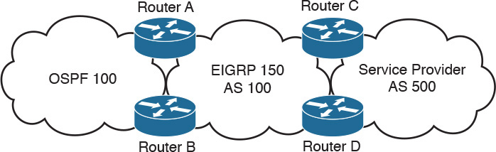
61. Where should you configure BGP?
a. Routers A and B
b. Routers C and D
c. Answers A and B
d. Routers A and C
62. On which router should you configure redistribution for OSPF and EIGRP?
a. Router A only.
b. Router B only.
c. Routers A and B.
d. Redistribution occurs automatically.
63. To announce the networks from autonomous system 100 to autonomous system 500, which routing protocols should you redistribute into BGP?
a. OSPF only
b. EIGRP only
c. OSPF and EIGRP
d. iBGP
64. Where should you use filters?
a. Routers A and B
b. Routers C and D
c. Routers A and C
d. Answers A and B