Chapter 5
VLSMs, Summarization, and Troubleshooting TCP/IP
The following ICND1 exam topics are covered in this chapter:
- IP addressing (IPv4 / IPv6)
- Identify the appropriate IPv4 addressing scheme using VLSM and summarization to satisfy addressing requirements in a LAN/WAN environment.
- Troubleshooting
- Troubleshoot and correct common problems associated with IP addressing and host configurations.
Now that IP addressing and subnetting have been thoroughly covered in the last two chapters, you’re now fully prepared and ready to learn all about variable length subnet masks (VLSMs). I’ll also show you how to design and implement a network using VLSM in this chapter. After ensuring you’ve mastered VLSM design and implementation, I’ll demonstrate how to summarize classful boundaries.
We’ll wrap up the chapter by going over IP address troubleshooting, focusing on the steps Cisco recommends to follow when troubleshooting an IP network.
So get psyched because this chapter will give you powerful tools to hone your knowledge of IP addressing and networking and seriously refine the important skills you’ve gained so far. So stay with me—I guarantee that your hard work will pay off! Ready? Let’s go!
Variable Length Subnet Masks (VLSMs)
Teaching you a simple way to create many networks from a large single network using subnet masks of different lengths in various kinds of network designs is what my primary focus will be in this chapter. Doing this is called VLSM networking, and it brings up another important subject I mentioned in Chapter 4, “Easy Subnetting,” classful and classless networking.
Older routing protocols like Routing Information Protocol version 1 (RIPv1) do not have a field for subnet information, so the subnet information gets dropped. This means that if a router running RIP has a subnet mask of a certain value, it assumes that all interfaces within the classful address space have the same subnet mask. This is called classful routing, and RIP is considered a classful routing protocol. We’ll cover RIP and the difference between classful and classless networks later on in Chapter 8, “IP Routing,” but for now, just remember that if you try to mix and match subnet mask lengths in a network that’s running an old routing protocol, such as RIP, it just won’t work!
However, classless routing protocols do support the advertisement of subnet information, which means you can use VLSM with routing protocols such as RIPv2, Enhanced Interior Gateway Protocol (EIGRP), and Open Shortest Path First (OSPF). The benefit of this type of network is that it saves a bunch of IP address space.
As the name suggests, VLSMs can use subnet masks with different lengths for different router interfaces. Check out Figure 5-1 to see an example of why classful network designs are inefficient.
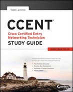
Figure 5-1: Typical classful network
Looking at Figure 5-1, you can see that there are two routers, each with two LANs and connected together with a WAN serial link. In a typical classful network design that’s running RIP, you could subnet a network like this:
Our subnets would be—you know this part, right?— 0, 16, 32, 48, 64, 80, etc., which allows us to assign 16 subnets to our internetwork. But how many hosts would be available on each network? Well, as you know by now, each subnet provides only 14 hosts, so each LAN has only 14 valid hosts available (don’t forget that the router interface needs an address too and is included in the amount of needed valid hosts). This means that one LAN doesn’t even have enough addresses needed for all the hosts, and this network as it is shown would not work as addressed in the figure! Since the point-to-point WAN link also has 14 valid hosts, it would be great to be able to nick a few valid hosts from that WAN link to give to our LANs!
All hosts and router interfaces have the same subnet mask—again, known as classful routing—and if we want this network to be efficient, we would definitely need to add different masks to each router interface.
But that’s not our only problem—the link between the two routers will never use more than two valid hosts! This wastes valuable IP address space, and it’s the big reason you need to learn about VLSM network design.
VLSM Design
Let’s take Figure 5-1 and use a classless design instead, which will become the new network shown in Figure 5-2. In the previous example, we wasted address space—one LAN didn’t have enough addresses because every router interface and host used the same subnet mask. Not so good. A better solution would be to provide for only the needed number of hosts on each router interface, and we’re going to use VLSMs to achieve that goal.
Figure 5-2: Classless network design

Now remember that we can use different size masks on each router interface. If we use a /30 on our WAN links and a /27, /28, and /29 on our LANs, we’ll get 2 hosts per WAN interface and 30, 14, and 6 hosts per LAN interface—nice! This makes a huge difference—not only can we get just the right amount of hosts on each LAN, we still have room to add more WANs and LANs using this same network!
Implementing VLSM Networks
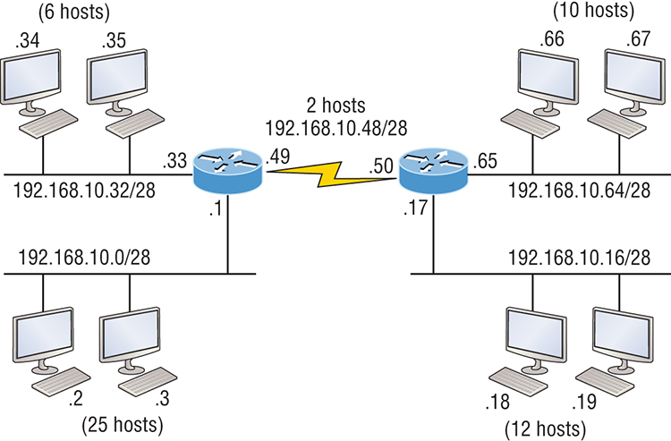
To create VLSMs quickly and efficiently, you need to understand how block sizes and charts work together to create the VLSM masks. Table 5-1 shows you the block sizes used when creating VLSMs with Class C networks. For example, if you need 25 hosts, then you’ll need a block size of 32. If you need 11 hosts, you’ll use a block size of 16. Need 40 hosts? Then you’ll need a block of 64. You cannot just make up block sizes—they’ve got to be the block sizes shown in Table 5-1. So memorize the block sizes in this table—it’s easy. They’re the same numbers we used with subnetting!
Table 5-1: Block sizes
The next step is to create a VLSM table. Figure 5-3 shows you the table used in creating a VLSM network. The reason we use this table is so we don’t accidentally overlap networks.
You’ll find the sheet shown in Figure 5-3 very valuable because it lists every block size you can use for a network address. Notice that the block sizes start at 4 and advance all the way up to a block size of 128. If you have two networks with block sizes of 128, you can have only 2 networks. With a block size of 64, you can have only 4, and so on, all the way to 64 networks using a block size of 4. Of course, this is assuming you’re using the ip subnet-zero command in your network design.
So now all you need to do is fill in the chart in the lower-left corner, then add the subnets to the worksheet and you’re good to go!
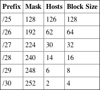
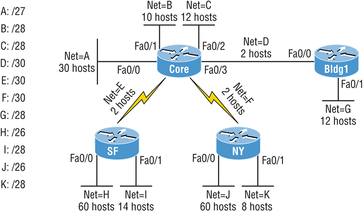
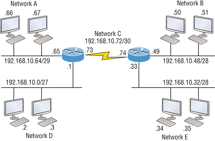
Based on what you’ve learned so far about block sizes and the VLSM table, let’s create a VLSM network using a Class C network address 192.168.10.0 for the network in Figure 5-4, then fill out the VLSM table, as shown in Figure 5-5.
In Figure 5-4, we have four WAN links and four LANs connected together, so we need to create a VLSM network that will save address space. Looks like we have two block sizes of 32, a block size of 16, and a block size of 8, and our WANs each have a block size of 4. Take a look and see how I filled out our VLSM chart in Figure 5-5.
There are two important things to note here, the first is that we still have plenty of room for growth with this VLSM network design. The second point is that we could never achieve this goal with one subnet mask using classful routing.
Figure 5-3: The VLSM table

Figure 5-4: VLSM network example 1
Let’s do another one. Figure 5-6 shows a network with 11 networks, two block sizes of 64, one of 32, five of 16, and three of 4.
First, create your VLSM table and use your block size chart to fill in the table with the subnets you need. Figure 5-7 shows a possible solution.
Notice that I filled in this entire chart and only have room for one more block size of 4. You can only gain that amount of address space savings with a VLSM network!
Keep in mind that it doesn’t matter where you start your block sizes as long as you always begin counting from zero. For example, if you had a block size of 16, you must start at 0 and incrementally progress from there—0, 16, 32, 48, and so on. You can’t start with a block size of 16 or some value like 40, and you can’t progress using anything but increments of 16.
Here’s another example. If you had block sizes of 32, start at zero like this: 0, 32, 64, 96, etc. Again, you don’t get to start wherever you want; you must always start counting from zero. In the example in Figure 5-7, I started at 64 and 128, with my two block sizes of 64. I didn’t have much choice because my options are 0, 64, 128, and 192. However, I added the block size of 32, 16, 8, and 4 elsewhere, but they were always in the correct increments required of the specific block size. Remember that if you always start with the largest blocks first, then make your way to the smaller blocks sizes, you will automatically fall on an increment boundary. It also guarantees that you are using your address space in the most effective way.
Okay—you have three locations you need to address, and the IP network you have received is 192.168.55.0 to use as the addressing for the entire network. You’ll use ip subnet-zero and RIPv2 as the routing protocol because RIPv2 supports VLSM networks but RIPv1 does not. Figure 5-8 shows the network diagram and the IP address of the RouterA S0/0 interface.
Figure 5-5: VLSM table example 1

Figure 5-6: VLSM network example 2
From the list of IP addresses on the right of the figure, which IP address do you think will be placed in each router’s FastEthernet 0/0 interface and serial 0/1 of RouterB?
To answer this, look for clues in Figure 5-8. The first is that interface S0/0 on RouterA has IP address 192.168.55.2/30 assigned, which makes for an easy answer because A /30 is 255.255.255.252, which gives you a block size of 4. Your subnets are 0, 4, 8, etc. Since the known host has an IP address of 2, the only other valid host in the zero subnet is 1, so the third answer down is the right one for the S0/1 interface of RouterB.
The next clues are the listed number of hosts for each of the LANs. RouterA needs 7 hosts—a block size of 16 (/28). RouterB needs 90 hosts—a block size of 128 (/25). And RouterC needs 23 hosts—a block size of 32 (/27).
Figure 5-9 illustrates this solution.
This is actually pretty simple because once you’ve figured out the block size needed for each LAN, all you need to get to the right solution is to identify proper clues and, of course, know your block sizes well!
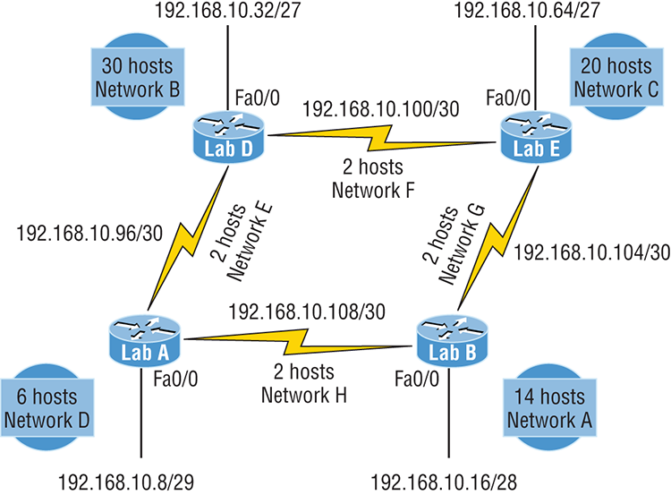
One last example of VLSM design before we move on to summarization. Figure 5-10 shows three routers, all running RIPv2. Which Class C addressing scheme would you use to maintain the needs of this network while saving as much address space as possible?
This is actually a pretty clean network design that’s just waiting for you to fill out the chart. There are block sizes of 64, 32, and 16 and two block sizes of 4. Coming up with the right solution should be a slam dunk! Take a look at my answer in Figure 5-11.
My solution began at subnet 0, and I used the block size of 64. Clearly, I didn’t have to go with a block size of 64 because I could’ve chosen a block size of 4 instead. But I didn’t because I usually like to start with the largest block size and move to the smallest. With that done, I added the block sizes of 32 and 16 as well as the two block sizes of 4. This solution is optimal because it still leaves lots of room to add subnets to this network!
Figure 5-7: VLSM table example 2
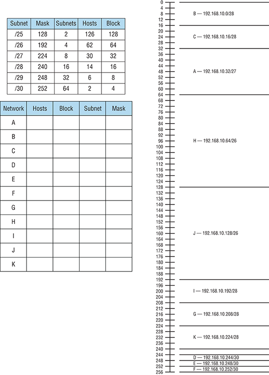
Figure 5-8: VLSM design example 1
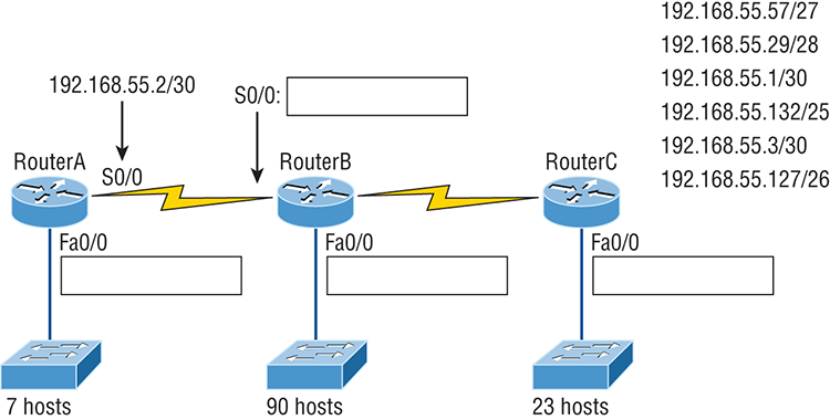
Figure 5-9: Solution to VLSM design example 1
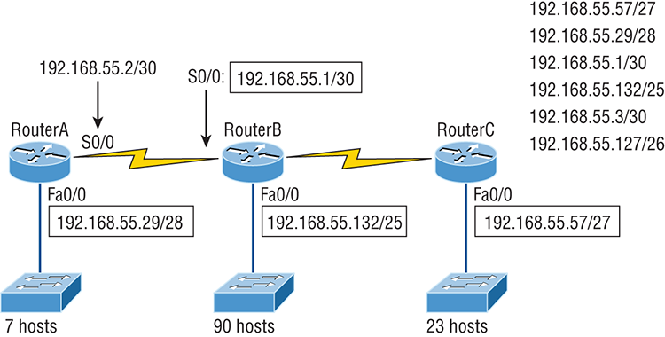
Figure 5-10: VLSM design example 2

Figure 5-11: Solution to VLSM design example 2

Summarization
Summarization, also called route aggregation, allows routing protocols to advertise many networks as one address. The purpose of this is to reduce the size of routing tables on routers to save memory, which also shortens the amount of time IP requires to parse the routing table when determining the best path to a remote network.
Figure 5-12 shows how a summary address would be used in an internetwork.
Figure 5-12: Summary address used in an internetwork
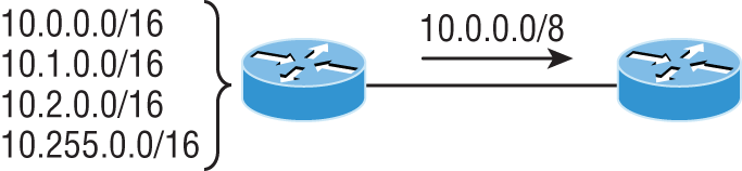
Summarization is pretty straightforward because all you really need to have down is a solid understanding of the block sizes we’ve been using for subnetting and VLSM design. For example, if you wanted to summarize the following networks into one network advertisement, you just have to find the block size first, which will make it easy to find your answer:
Okay—so what’s the block size? Well, there are exactly 16 Class C networks, which fit neatly into a block size of 16.
Now that we’ve determined the block size, we just need to find the network address and mask used to summarize these networks into one advertisement. The network address used to advertise the summary address is always the first network address in the block—in this example, 192.168.16.0. To figure out a summary mask, we just need to figure out which mask will get us a block size of 16. If you came up with 240, you got it right! 240 would be placed in the third octet, which is exactly the octet where we’re summarizing, so the mask would be 255.255.240.0.
Here’s another example:
This isn’t as clean as the previous example because there are two possible answers. Here’s why: Since you’re starting at network 32, your options for block sizes are 4, 8, 16, 32, 64, etc., and block sizes of 16 and 32 could work as this summary address. Let’s explore your two options:
- If you went with a block size of 16, then the network address would be 172.16.32.0 with a mask of 255.255.240.0 (240 provides a block of 16). The problem is that this only summarizes from 32 to 47, which means that networks 48 through 50 would be advertised as single networks. Even so, this could still be a good solution depending on your network design.
- If you decided to go with a block size of 32 instead, then your summary address would still be 172.16.32.0, but the mask would be 255.255.224.0 (224 provides a block of 32). The possible problem with this answer is that it will summarize networks 32 through 63 and we only have networks 32 to 50. No worries if you’re planning on adding networks 51 to 63 later into the same network, but you could have serious problems in your internetwork if somehow networks 51 to 63 were to show up and be advertised from somewhere else in your network! So even though this option does allow for growth, it’s a lot safer to go with option #1.
Let’s take a look at another example: Your summary address is 192.168.144.0/20, so what’s the range of host addresses that would be forwarded according to this summary? The /20 provides a summary address of 192.168.144.0 and mask of 255.255.240.0.
The third octet has a block size of 16, and starting at summary address 144, the next block of 16 is 160, so your network summary range is 144 to 159 in the third octet. This is why it comes in handy to be able to count in 16s!
A router with this summary address in the routing table will forward any packet having destination IP addresses of 192.168.144.1 through 192.168.159.254.
Only two more summarization examples, then we’ll move on to troubleshooting.
In summarization example 4, Figure 5-13, the Ethernet networks connected to router R1 are being summarized to R2 as 192.168.144.0/20. Which range of IP addresses will R2 forward to R1 according to this summary?
Figure 5-13: Summarization example 4. The Ethernet networks connected to router R1 are being summarized to R2 as 192.168.144.0/20. Which IP addresses will R2 forward to R1 according to this summary?

No worries—solving this is easier than it looks initially. The question actually has the summary address listed in it: 192.168.144.0/20. You already know that /20 is 255.255.240.0, which means you’ve got a block size of 16 in the third octet. Starting at 144, which is also right there in the question, makes the next block size of 16 equal 160. You can’t go above 159 in the third octet, so the IP addresses that will be forwarded are 192.168.144.1 through 192.168.159.254.
Okay, last one. In Figure 5-14, there are five networks connected to router R1. What’s the best summary address to R2?
Figure 5-14: Summarization example 5
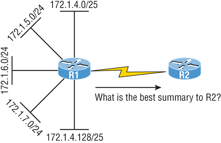
I’ll be honest with you—this is a much harder question than the one in Figure 5-13, so you’re going to have to look carefully to see the answer. A good approach here would be to write down all the networks and see if you can find anything in common with all of them:
- 172.1.4.128/25
- 172.1.7.0/24
- 172.1.6.0/24
- 172.1.5.0/24
- 172.1.4.0/25
Do you see an octet that looks interesting to you? I do. It’s the third octet. 4, 5, 6, 7, and yes, it’s a block size of 4. So you can summarize 172.1.4.0 using a mask of 255.255.252.0, meaning you would use a block size of 4 in the third octet. The IP addresses forwarded with this summary would be 172.1.4.1 through 172.1.7.255.
To summarize the summarization section, if you’ve nailed down your block sizes, then finding and applying summary addresses and masks is a relatively straightforward task. But you’re going to get bogged down pretty quickly if you don’t know what a /20 is or if you can’t count by 16s!
Troubleshooting IP Addressing
Because running into trouble now and then in networking is a given, being able to troubleshoot IP addressing is clearly a vital skill. I’m not being negative here—just realistic. The positive side to this is that if you’re the one equipped with the tools to diagnose and clear up the inevitable trouble, you get to be the hero when you save the day! Even better? You can usually fix an IP network regardless of whether you’re on site or at home!
So this is where I’m going to show you the “Cisco way” of troubleshooting IP addressing. Let’s use Figure 5-15 as an example of your basic IP trouble—poor Sally can’t log in to the Windows server. Do you deal with this by calling the Microsoft team to tell them their server is a pile of junk and causing all your problems? Though tempting, a better approach is to first double-check and verify your network instead.
Figure 5-15: Basic IP troubleshooting

Okay, let’s get started by going through the troubleshooting steps that Cisco recommends. They’re pretty simple, but important nonetheless. Pretend you’re at a customer host and they’re complaining that they can’t communicate to a server that just happens to be on a remote network. Here are the four troubleshooting steps Cisco recommends:
C:>ping 127.0.0.1
Pinging 127.0.0.1 with 32 bytes of data:
Reply from 127.0.0.1: bytes=32 time<1ms TTL=128
Reply from 127.0.0.1: bytes=32 time<1ms TTL=128
Reply from 127.0.0.1: bytes=32 time<1ms TTL=128
Reply from 127.0.0.1: bytes=32 time<1ms TTL=128
Ping statistics for 127.0.0.1:
    Packets: Sent = 4, Received = 4, Lost = 0 (0% loss),
Approximate round trip times in milli-seconds:
Minimum = 0ms, Maximum = 0ms, Average = 0msC:>ping 172.16.10.2
Pinging 172.16.10.2 with 32 bytes of data:
Reply from 172.16.10.2: bytes=32 time<1ms TTL=128
Reply from 172.16.10.2: bytes=32 time<1ms TTL=128
Reply from 172.16.10.2: bytes=32 time<1ms TTL=128
Reply from 172.16.10.2: bytes=32 time<1ms TTL=128
Ping statistics for 172.16.10.2:
Packets: Sent = 4, Received = 4, Lost = 0 (0% loss),
Approximate round trip times in milli-seconds:
Minimum = 0ms, Maximum = 0ms, Average = 0msC:>ping 172.16.10.1
Pinging 172.16.10.1 with 32 bytes of data:
Reply from 172.16.10.1: bytes=32 time<1ms TTL=128
Reply from 172.16.10.1: bytes=32 time<1ms TTL=128
Reply from 172.16.10.1: bytes=32 time<1ms TTL=128
Reply from 172.16.10.1: bytes=32 time<1ms TTL=128
Ping statistics for 172.16.10.1:
Packets: Sent = 4, Received = 4, Lost = 0 (0% loss),
Approximate round trip times in milli-seconds:
Minimum = 0ms, Maximum = 0ms, Average = 0msC:>ping 172.16.20.2
Pinging 172.16.20.2 with 32 bytes of data:
Reply from 172.16.20.2: bytes=32 time<1ms TTL=128
Reply from 172.16.20.2: bytes=32 time<1ms TTL=128
Reply from 172.16.20.2: bytes=32 time<1ms TTL=128
Reply from 172.16.20.2: bytes=32 time<1ms TTL=128
Ping statistics for 172.16.20.2:
Packets: Sent = 4, Received = 4, Lost = 0 (0% loss),
Approximate round trip times in milli-seconds:
Minimum = 0ms, Maximum = 0ms, Average = 0msIf the user still can’t communicate with the server after steps 1 through 4 have been completed successfully, you probably have some type of name resolution problem and need to check your Domain Name System (DNS) settings. But if the ping to the remote server fails, then you know you have some type of remote physical network problem and need to go to the server and work through steps 1 through 3 until you find the snag.
Before we move on to determining IP address problems and how to fix them, I just want to mention some basic commands that you can use to help troubleshoot your network from both a PC and a Cisco router. Keep in mind that though these commands may do the same thing, they’re implemented differently.
Once you’ve gone through all these steps and, if necessary, used the appropriate commands, what do you do when you find a problem? How do you go about fixing an IP address configuration error? Time to cover the next step—determining and fixing the issue at hand!
Determining IP Address Problems
It’s common for a host, router, or other network device to be configured with the wrong IP address, subnet mask, or default gateway. Because this happens way too often, you must know how to find and fix IP address configuration errors.
A good way to start is to draw out the network and IP addressing scheme. If that’s already been done, consider yourself lucky because though sensible, it’s rarely done. Even if it is, it’s usually outdated or inaccurate anyway. So either way, it’s a good idea to bite the bullet and start from scratch.
Once you have your network accurately drawn out, including the IP addressing scheme, you need to verify each host’s IP address, mask, and default gateway address to establish the problem. Of course, this is assuming that you don’t have a physical layer problem, or if you did, that you’ve already fixed it.
Let’s check out the example illustrated in Figure 5-16. A user in the sales department calls and tells you that she can’t get to ServerA in the marketing department. You ask her if she can get to ServerB in the marketing department, but she doesn’t know because she doesn’t have rights to log on to that server. What do you do?
First, guide your user through the four troubleshooting steps you learned in the preceding section. Okay—let’s say steps 1 through 3 work but step 4 fails. By looking at the figure, can you determine the problem? Look for clues in the network drawing. First, the WAN link between the Lab_A router and the Lab_B router shows the mask as a /27. You should already know that this mask is 255.255.255.224 and determine that all networks are using this mask. The network address is 192.168.1.0. What are our valid subnets and hosts? 256 – 224 = 32, so this makes our subnets 0, 32, 64, 96, 128, etc. So, by looking at the figure, you can see that subnet 32 is being used by the sales department. The WAN link is using subnet 96, and the marketing department is using subnet 64.
Figure 5-16: IP address problem 1
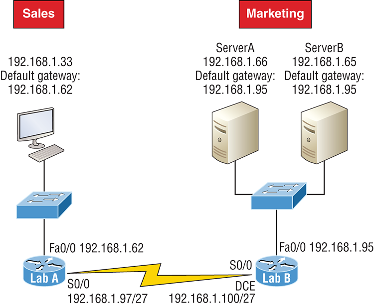
Now you’ve got to establish what the valid host ranges are for each subnet. From what you learned at the beginning of this chapter, you should now be able to easily determine the subnet address, broadcast addresses, and valid host ranges. The valid hosts for the Sales LAN are 33 through 62, and the broadcast address is 63 because the next subnet is 64, right? For the Marketing LAN, the valid hosts are 65 through 94 (broadcast 95), and for the WAN link, 97 through 126 (broadcast 127). By closely examining the figure, you can determine that the default gateway on the Lab_B router is incorrect. That address is the broadcast address for subnet 64, so there’s no way it could be a valid host!

Did you get all that? Let’s try another one to make sure. Figure 5-17 shows a network problem. A user in the Sales LAN can’t get to ServerB. You have the user run through the four basic troubleshooting steps and find that the host can communicate to the local network but not to the remote network. Find and define the IP addressing problem.
If you went through the same steps used to solve the last problem, you can see that first, the WAN link again provides the subnet mask to use— /29, or 255.255.255.248. Assuming classful addressing, you need to determine what the valid subnets, broadcast addresses, and valid host ranges are to solve this problem.
Figure 5-17: IP address problem 2

The 248 mask is a block size of 8 (256 – 248 = 8, as discussed in Chapter 4), so the subnets both start and increment in multiples of 8. By looking at the figure, you see that the Sales LAN is in the 24 subnet, the WAN is in the 40 subnet, and the Marketing LAN is in the 80 subnet. Can you see the problem yet? The valid host range for the Sales LAN is 25–30, and the configuration appears correct. The valid host range for the WAN link is 41–46, and this also appears correct. The valid host range for the 80 subnet is 81–86, with a broadcast address of 87 because the next subnet is 88. ServerB has been configured with the broadcast address of the subnet.
Okay, now that you can figure out misconfigured IP addresses on hosts, what do you do if a host doesn’t have an IP address and you need to assign one? What you need to do is scrutinize the other hosts on the LAN and figure out the network, mask, and default gateway. Let’s take a look at a couple of examples of how to find and apply valid IP addresses to hosts.
You need to assign a server and router IP addresses on a LAN. The subnet assigned on that segment is 192.168.20.24/29. The router needs to be assigned the first usable address and the server needs the last valid host ID. What is the IP address, mask, and default gateway assigned to the server?
To answer this, you must know that a /29 is a 255.255.255.248 mask, which provides a block size of 8. The subnet is known as 24, the next subnet in a block of 8 is 32, so the broadcast address of the 24 subnet is 31 and the valid host range is 25–30.
Take a look at Figure 5-18 and solve this problem.
Figure 5-18: Find the valid host #1
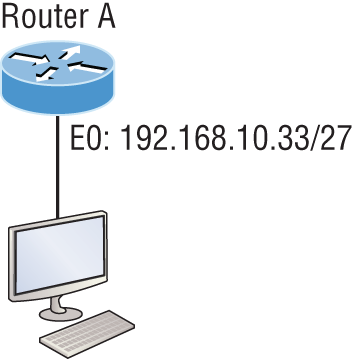
Look at the router’s IP address on Ethernet0. What IP address, subnet mask, and valid host range could be assigned to the host?
The IP address of the router’s Ethernet0 is 192.168.10.33/27. As you already know, a /27 is a 224 mask with a block size of 32. The router’s interface is in the 32 subnet. The next subnet is 64, so that makes the broadcast address of the 32 subnet 63 and the valid host range 33–62.
Figure 5-19 shows two routers with Ethernet configurations already assigned. What are the host addresses and subnet masks of HostA and HostB?
Figure 5-19: Find the valid host #2
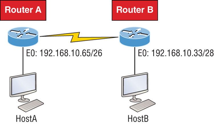
RouterA has an IP address of 192.168.10.65/26 and RouterB has an IP address of 192.168.10.33/28. What are the host configurations? RouterA Ethernet0 is in the 192.168.10.64 subnet and RouterB Ethernet0 is in the 192.168.10.32 network.
Just a couple more examples before you can put this chapter behind you—hang in there!
Figure 5-20 shows two routers. You need to configure the S0/0 interface on RouterA. The network assigned to the serial link is 172.16.17.0/22. What IP address can be assigned?
Figure 5-20: Find the valid host address #3
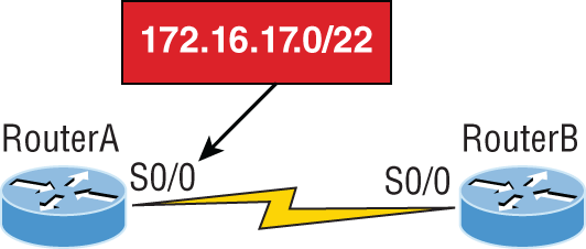
First, know that a /22 CIDR is 255.255.252.0, which makes a block size of 4 in the third octet. Since 17 is listed, the available range is 16.1 through 19.254, so in this example, the IP address S0/0 could be 172.16.18.255 since that’s within the range.
Okay, last one! You need to find a classful network add that has one Class C network ID and you need to provide one usable subnet per city while allowing enough usable host addresses for each city specified in Figure 5-21. What is your mask?
Figure 5-21: Find the valid subnet mask.
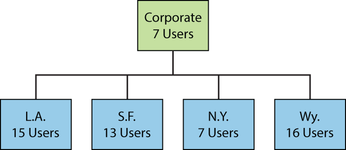
Actually, this is probably the easiest thing you’ve done all day! I count 5 subnets needed, and the Wyoming office needs 16 users—always look for the network that needs the most hosts! What block size is needed for the Wyoming office? Your answer is 32. You can’t use a block size of 16 because you always have to subtract 2. What mask provides you with a block size of 32? 224 is your answer because this provides 8 subnets, each with 30 hosts.
You’re done—the diva has sung and the chicken has safely crossed the road…whew! Time to take a break, but skip the shot and the beer if that’s what you had in mind because you need to have your head straight to go through the written lab and review questions next!
Summary
Again, if you got to this point without getting lost along the way a few times, you’re awesome, but if you did get lost, don’t stress because most people do! Just be patient with yourself and go back over the material that tripped you up until it’s all crystal clear. You’ll get there!
This chapter provided you with keys to understanding the oh-so-very-important topic of variable length subnet masks. You should also know how to design and implement simple VLSM networks and be clear on summarization as well.
And make sure you understand and memorize Cisco’s troubleshooting methods. You must remember the four steps that Cisco recommends to take when trying to narrow down exactly where a network and/or IP addressing problem is and then know how to proceed systematically to fix it. In addition, you should be able to find valid IP addresses and subnet masks by looking at a network diagram.
Exam Essentials
Written Lab 5
The answers to this lab can be found in Appendix A, “Answers to Written Labs.”
For each of the following sets of networks, determine the summary address and the mask to be used that will summarize the subnets.
Review Questions
The answers to these questions can be found in Appendix B, “Answers to Chapter Review Questions.”
1. On a VLSM network, which mask should you use on point-to-point WAN links in order to reduce the waste of IP addresses?
A. /27
B. /28
C. /29
D. /30
E. /31
2. In the network shown in the diagram, how many computers could be in subnet B?
A. 6
B. 12
C. 14
D. 30
3. In the diagram below, in order to have as efficient IP addressing as possible, which network should use a /29 mask?
A. A
B. B
C. C
D. D
4. To use VLSM, what capability must the routing protocols in use possess?
A. Support for multicast
B. Multiprotocol support
C. Transmission of subnet mask information
D. Support for unequal load balancing
5. What summary address would cover all the networks shown and advertise a single, efficient route to Router B that won’t advertise more networks than needed?
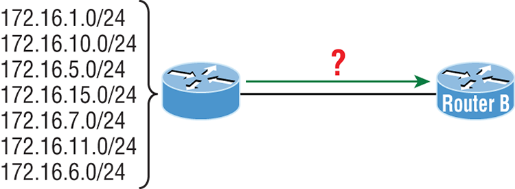
A. 172.16.0.0/24
B. 172.16.1.0/24
C. 172.16.0.0/24
D. 172.16.0.0/20
E. 172.16.16.0/28
F. 172.16.0.0/27
6. In the diagram below what is the most likely reason the station cannot ping outside of its network?
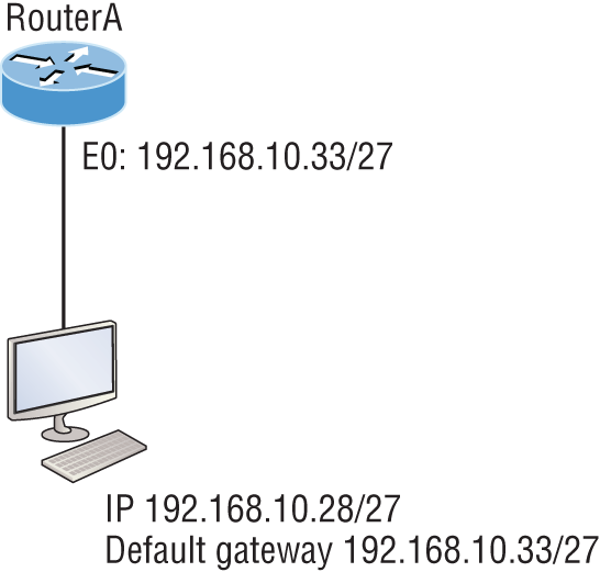
A. The IP address is incorrect on E0 of the router.
B. The default gateway address is incorrect on the station.
C. The IP address on the station is incorrect.
D. The router is malfunctioning.
7. If Host A is configured with an incorrect default gateway and all other computers and the router are known to be configured correctly, which of the following statements is TRUE?
A. Host A cannot communicate with the router.
B. Host A can communicate with other hosts in the same subnet.
C. Host A can communicate with hosts in other subnets.
D. Host A can communicate with no other systems.
8. Which of the following troubleshooting steps, if completed successfully, also confirms the other steps will succeed as well?
A. ping a remote computer
B. ping the loopback address
C. ping the NIC
D. ping the default gateway
9. When a ping to the local host IP address fails, what can you assume?
A. The IP address of the local host is incorrect.
B. The IP address of the remote host is incorrect.
C. The NIC is not functional.
D. The IP stack has failed to initialize.
10. When a ping to the local host IP address succeeds but a ping to the default gateway IP address fails, what can you rule out? (Choose all that apply.)
A. The IP address of the local host is incorrect.
B. The IP address of the gateway is incorrect.
C. The NIC is not functional.
D. The IP stack has failed to initialize.
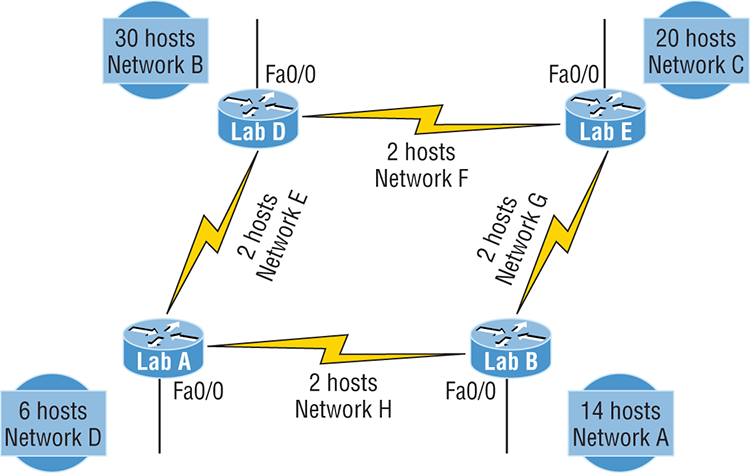
11. Which of the networks in the diagram could use a /29 mask?

A. Corporate
B. LA
C. SF
D. NY
E. none
12. What network service is the most likely problem if you can ping a computer by IP address but not by name?
A. DNS
B. DHCP
C. ARP
D. ICMP
13. When you issue the ping command, what protocol are you using?
A. DNS
B. DHCP
C. ARP
D. ICMP
14. Which of the following commands displays the networks traversed on a path to a network destination?
A. ping
B. traceroute
C. pingroute
D. pathroute
15. What command generated the output shown below?
Reply from 172.16.10.2: bytes=32 time<1ms TTL=128
Reply from 172.16.10.2: bytes=32 time<1ms TTL=128
Reply from 172.16.10.2: bytes=32 time<1ms TTL=128
Reply from 172.16.10.2: bytes=32 time<1ms TTL=128A. traceroute
B. show ip route
C. ping
D. pathping
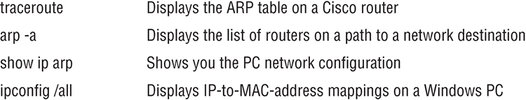
16. In the work area, match the command to its function on the right.
17. Which of the following network addresses correctly summarizes the three networks shown below efficiently?
10.0.0.0/16
10.1.0.0/16
10.2.0.0/16
A. 10.0.0.0/15
B. 10.1.0.0/8
C. 10.0.0.0/14
D. 10.0.0.8/16
18. What command displays the ARP table on a Cisco router?
A. show ip arp
B. traceroute
C. arp -a
D. tracert
19. What switch must be added to the ipconfig command on a PC to verify DNS configuration?
A. /dns
B. -dns
C. /all
D. showall
20. Which of the following is the best summarization of the following networks: 192.168.128.0 through 192.168.159.0
A. 192.168.0.0/24
B. 192.168.128.0/16
C. 192.168.128.0/19
D. 192.168.128.0/20