Appendix A
Answers to Written Labs
Chapter 1: Internetworking
Written Lab 1.1: OSI Questions
1. The Application layer is responsible for finding the network resources broadcast from a server and adding flow control and error control (if the application developer chooses).
2. The Physical layer takes frames from the Data Link layer and encodes the 1s and 0s into a digital signal for transmission on the network medium.
3. The Network layer provides routing through an internetwork and logical addressing.
4. The Presentation layer makes sure that data is in a readable format for the Application layer.
5. The Session layer sets up, maintains, and terminates sessions between applications.
6. PDUs at the Data Link layer are called frames and provide physical addressing plus other options to place packets on the network medium.
7. The Transport layer uses virtual circuits to create a reliable connection between two hosts.
8. The Network layer provides logical addressing, typically IP addressing and routing.
9. The Physical layer is responsible for the electrical and mechanical connections between devices.
10. The Data Link layer is responsible for the framing of data packets.
11. The Session layer creates sessions between different hosts’ applications.
12. The Data Link layer frames packets received from the Network layer.
13. The Transport layer segments user data.
14. The Network layer creates packets out of segments handed down from the Transport layer.
15. The Physical layer is responsible for transporting 1s and 0s (bits) in a digital signal.
16. Segments, packets, frames, bits
17. Transport
18. Data Link
19. Network
20. 48 bits (6 bytes) expressed as a hexadecimal number
Written Lab 1.2: Defining the OSI Layers and Devices
| Description | Device or OSI Layer |
| This device sends and receives information about the Network layer. | Router |
| This layer creates a virtual circuit before transmitting between two end stations. | Transport |
| This device uses hardware addresses to filter a network. | Bridge or switch |
| Ethernet is defined at these layers. | Data Link and Physical |
| This layer supports flow control, sequencing, and acknowledgments. | Transport |
| This device can measure the distance to a remote network. | Router |
| Logical addressing is used at this layer. | Network |
| Hardware addresses are defined at this layer. | Data Link (MAC sublayer) |
| This device creates one big collision domain and one large broadcast domain. | Hub |
| This device creates many smaller collision domains, but the network is still one large broadcast domain. | Switch or bridge |
| This device can never run full-duplex. | Hub |
| This device breaks up collision domains and broadcast domains. | Router |
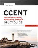
Written Lab 1.3: Identifying Collision and Broadcast Domains
A. Hub: One collision domain, one broadcast domain
B. Bridge: Two collision domains, one broadcast domain
C. Switch: Four collision domains, one broadcast domain
D. Router: Three collision domains, three broadcast domains
Chapter 2: Ethernet Networking and Data Encapsulation
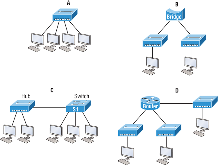
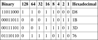
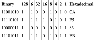
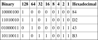
Written Lab 2.1: Binary/Decimal/Hexadecimal Conversion
1.
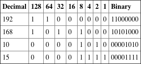

2.
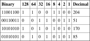
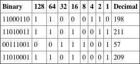
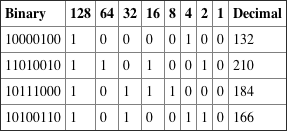
3.
Written Lab 2.2: CSMA/CD Operations
When a collision occurs on an Ethernet LAN, the following happens:
1. A jam signal informs all devices that a collision occurred.
2. The collision invokes a random back-off algorithm.
3. Each device on the Ethernet segment stops transmitting for a short time until the timers expire.
4. All hosts have equal priority to transmit after the timers have expired.
Written Lab 2.3: Cabling
1. Crossover
2. Straight-through
3. Crossover
4. Crossover
5. Straight-through
6. Crossover
7. Crossover
8. Rolled
Written Lab 2.4: Encapsulation
At a transmitting device, the data encapsulation method works like this:
1. User information is converted to data for transmission on the network.
2. Data is converted to segments, and a reliable connection is set up between the transmitting and receiving hosts.
3. Segments are converted to packets or datagrams, and a logical address is placed in the header so each packet can be routed through an internetwork.
4. Packets or datagrams are converted to frames for transmission on the local network. Hardware (Ethernet) addresses are used to uniquely identify hosts on a local network segment.
5. Frames are converted to bits, and a digital encoding and clocking scheme is used.
Chapter 3: Introduction to TCP/IP
Written Lab 3.1: TCP/IP
1. 192 through 223, 110xxxxx
2. Host-to-host
3. 1 through 126
4. Loopback or diagnostics
5. Turn all host bits off.
6. Turn all host bits on.
7. 10.0.0.0 through 10.255.255.255
8. 172.16.0.0 through 172.31.255.255
9. 192.168.0.0 through 192.168.255.255
10. 0 through 9 and A, B, C, D, E, and F
Written Lab 3.2: Mapping Applications to the DoD Model
1. Internet
2. Process/Application
3. Process/Application
4. Process/Application
5. Process/Application
6. Internet
7. Process/Application
8. Host-to-host
9. Process/Application
10. Host-to-host
11. Process/Application
12. Internet
13. Internet
14. Internet
15. Process/Application
16. Process/Application
17. Process/Application
Chapter 4: Easy Subnetting
Written Lab 4.1: Written Subnet Practice #1
1. 192.168.100.25/30. A /30 is 255.255.255.252. The valid subnet is 192.168.100.24, broadcast is 192.168.100.27, and valid hosts are 192.168.100.25 and 26.
2. 192.168.100.37/28. A /28 is 255.255.255.240. The fourth octet is a block size of 16. Just count by 16s until you pass 37. 0, 16, 32, 48. The host is in the 32 subnet, with a broadcast address of 47. Valid hosts 33–46.
3. A /27 is 255.255.255.224. The fourth octet is a block size of 32. Count by 32s until you pass the host address of 66. 0, 32, 64, 96. The host is in the 64 subnet, and the broadcast address is 95. Valid host range is 65–94.
4. 192.168.100.17/29. A /29 is 255.255.255.248. The fourth octet is a block size of 8. 0, 8, 16, 24. The host is in the 16 subnet, broadcast of 23. Valid hosts 17–22.
5. 192.168.100.99/26. A /26 is 255.255.255.192. The fourth octet has a block size of 64. 0, 64, 128. The host is in the 64 subnet, broadcast of 127. Valid hosts 65–126.
6. 192.168.100.99/25. A /25 is 255.255.255.128. The fourth octet is a block size of 128. 0, 128. The host is in the 0 subnet, broadcast of 127. Valid hosts 1–126.
7. A default Class B is 255.255.0.0. A Class B 255.255.255.0 mask is 256 subnets, each with 254 hosts. We need fewer subnets. If we used 255.255.240.0, this provides 16 subnets. Let’s add one more subnet bit. 255.255.248.0. This is 5 bits of subnetting, which provides 32 subnets. This is our best answer, a /21.
8. A /29 is 255.255.255.248. This is a block size of 8 in the fourth octet. 0, 8, 16. The host is in the 8 subnet, broadcast is 15.
9. A /29 is 255.255.255.248, which is 5 subnet bits and 3 host bits. This is only 6 hosts per subnet.
10. A /23 is 255.255.254.0. The third octet is a block size of 2. 0, 2, 4. The subnet is in the 16.2.0 subnet; the broadcast address is 16.3.255.
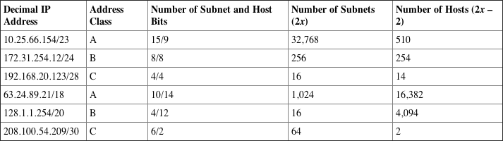
Written Lab 4.2: Written Subnet Practice #2
Written Lab 4.3: Written Subnet Practice #3
| Classful Address | Subnet Mask | Number of Hosts per Subnet (2x – 2) |
| /16 | 255.255.0.0 | 65,534 |
| /17 | 255.255.128.0 | 32,766 |
| /18 | 255.255.192.0 | 16,382 |
| /19 | 255.255.224.0 | 8,190 |
| /20 | 255.255.240.0 | 4,094 |
| /21 | 255.255.248.0 | 2,046 |
| /22 | 255.255.252.0 | 1,022 |
| /23 | 255.255.254.0 | 510 |
| /24 | 255.255.255.0 | 254 |
| /25 | 255.255.255.128 | 126 |
| /26 | 255.255.255.192 | 62 |
| /27 | 255.255.255.224 | 30 |
| /28 | 255.255.255.240 | 14 |
| /29 | 255.255.255.248 | 6 |
| /30 | 255.255.255.252 | 2 |
Written Lab 4.3: Written Subnet Practice #3
Chapter 5: VLSMs, Summarization and Troubleshooting TCP/IP
1. 192.168.0.0/20
2. 172.144.0.0 255.240.0.0
3. 192.168.32.0 255.255.224.0
4. 192.168.96.0 255.255.240.0
5. 66.66.0.0 255.255.240.0
6. 192.168.0.0/25
7. 172.16.1.0 255.255.248.0
8. 192.168.128.0 255.255.192.0
9. 53.60.96.0 255.255.224.0
10. 172.16.0.0 255.255.192.0
Chapter 6: Cisco’s Internetworking Operating System (IOS)
Written Lab 6
1. Router(config)#clock rate 1000000
2. Switch#config t
switch config)# line vty 0 15
switch(config-line)# no login
3. Switch#config t
Switch(config)# int f0/1
Switch(config-if)# no shutdown
4. Switch#erase startup-config
5. Switch#config t
Switch(config)# line console 0
Switch(config)# password todd
Switch(config)# login
6. Switch#config t
Switch(config)# enable secret cisco
7. Router#show controllers serial 0/2
8. Switch#show terminal
9. Switch#reload
10. Switch#config t
Switch(config)#hostname Sales
Chapter 7: Managing a Cisco Internetwork
Written Lab 7.1: IOS Management
1. copy start run
2. show cdp neighbor detail or show cdp entry *
3. show cdp neighbor
4. Ctrl+Shift+6, then X
5. show sessions
6. Either copy tftp run or copy start run
7. NTP
8. ip helper-address
9. ntp server ip_address version 4
10. show ntp status
Written Lab 7.2: Router Memory
1. Flash memory
2. ROM
3. NVRAM
4. ROM
5. RAM
6. RAM
7. ROM
8. ROM
9. RAM
10. RAM
Chapter 8: IP Routing
1. router(config)#ip route 172.16.10.0 255.255.255.0 172.16.20.1 150
2. It will use the gateway interface MAC at L2 and the actual destination IP at L3.
3. router(config)#ip route 0.0.0.0 0.0.0.0 172.16.40.1
4. Stub network
5. Router#show ip route
6. Exit interface
7. False. The MAC address would be the router interface, not the remote host.
8. True
9. router(config)#router rip
router(config-router)#passive-interface S1
10. True
Chapter 9: Open Shortest Path First (OSPF)
1. router ospf 101
2. show ip ospf
3. show ip ospf interface
4. show ip ospf neighbor
5. show ip route ospf
Chapter 10: Layer 2 Switching
1. show mac address-table
2. Flood the frame out all ports except the port on which it was received
3. Address learning, forward/filter decisions, and loop avoidance
4. It will add the source MAC address in the forward/filter table and associate it with the port on which the frame was received.
5. Maximum 1, violation shutdown
Chapter 11: VLANs and InterVLAN Routing
1. False! You do not provide an IP address under any physical port.
2. STP
3. Broadcast
4. Collision
5. switchport trunk encapsulation dot1q
6. Trunking allows you to make a single port part of multiple VLANs at the same time.
7. Frame identification (frame tagging) uniquely assigns a user-defined ID to each frame. This is sometimes referred to as a VLAN ID or color.
8. True
9. Access link
10. switchport trunk native vlan 4
Chapter 12: Security
1. access-list 10 deny 172.16.0.0 0.0.255.255
access-list 10 permit any
2. ip access-group 10 out
3. access-list 10 deny host 192.168.15.5
access-list 10 permit any
4. show access-lists
5. IDS, IPS
6. access-list 110 deny tcp host
172.16.10.1 host 172.16.30.5 eq 23
access-list 110 permit ip any any
7. line vty 0 4
access-class 110 in
8. ip access-list standard No172Net
deny 172.16.0.0 0.0.255.255
permit any
9. ip access-group No172Net out
10. show ip interfaces
Chapter 13: Network Address Translation
1. Port Address Translation (PAT), also called NAT Overload
2. debug ip nat
3. show ip nat translations
4. clear ip nat translations *
5. Before
6. After
7. show ip nat statistics
8. The ip nat inside and ip nat outside commands
9. Dynamic NAT
10. prefix-length
Chapter 14: Internet Protocol Version 6 (IPv6)
Written Lab 14.1
1. Unicast
2. Global unicast
3. Link-local
4. Unique local (used to be called site-local)
5. Multicast
6. Anycast
7. OSPFv3
8. ::1
9. FE80::/10
10. FC00:: /7
Written Lab 14.2
1. 2001:db8:1:1:090c:abff:fecd:1234
2. 2001:db8:1:1: 040c:32ff:fef1:a4d2
3. 2001:db8:1:1:12:abff:fecd:1234
4. 2001:db8:1:1:0f01:3aff:fe2f:1234
5. 2001:db8:1:1:080c:abff:feac:caba
..................Content has been hidden....................
You can't read the all page of ebook, please click here login for view all page.