Chapter 2
Ethernet Networking and Data Encapsulation
The following ICND1 exam topics are covered in this chapter:
- Operation of IP Data Networks
- Recognize the purpose and functions of various network devices such as Routers, Switches, Bridges and Hubs.
- Select the components required to meet a given network specification.
- Predict the data flow between two hosts across a network.
- Identify the appropriate media, cables, ports, and connectors to connect Cisco network devices to other network devices and hosts in a LAN
- LAN Switching Technologies
- Determine the technology and media access control method for Ethernet networks
- Identify basic switching concepts and the operation of Cisco switches.
- Collision Domains
- Broadcast Domains
Before we begin exploring a set of key foundational topics like the TCP/IP DoD model, IP addressing, subnetting, and routing in the upcoming chapters, I really want you to grasp the big picture of LANs conceptually. The role Ethernet plays in today’s networks as well as what Media Access Control (MAC) addresses are and how they are used are two more critical networking basics you’ll want a solid understanding of as well.
We’ll cover these important subjects and more in this chapter, beginning with Ethernet basics and the way MAC addresses are used on an Ethernet LAN, and then we’ll focus in on the actual protocols used with Ethernet at the Data Link layer. To round out this discussion, you’ll also learn about some very important Ethernet specifications.
You know by now that there are a whole bunch of different devices specified at the various layers of the OSI model and that it’s essential to be really familiar with the many types of cables and connectors employed to hook them up to the network correctly. I’ll review the types of cabling used with Cisco devices in this chapter, demonstrate how to connect to a router or switch, plus show you how to connect a router or switch via a console connection.
I’ll also introduce you to a vital process of encoding data as it makes its way down the OSI stack known as encapsulation.
I’m not nagging at all here—okay, maybe just a little, but promise that you’ll actually work through the four written labs and 20 review questions I added to the end of this chapter just for you. You’ll be so happy you did because they’re written strategically to make sure that all the important material covered in this chapter gets locked in, vault-tight into your memory. So don’t skip them!
Ethernet Networks in Review
Ethernet is a contention-based media access method that allows all hosts on a network to share the same link’s bandwidth. Some reasons it’s so popular are that Ethernet is really pretty simple to implement and it makes troubleshooting fairly straightforward as well. Ethernet is so readily scalable, meaning that it eases the process of integrating new technologies into an existing network infrastructure, like upgrading from Fast Ethernet to Gigabit Ethernet.
Ethernet uses both Data Link and Physical layer specifications, so you’ll be presented with information relative to both layers, which you’ll need to effectively implement, troubleshoot, and maintain an Ethernet network.
Collision Domain
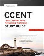
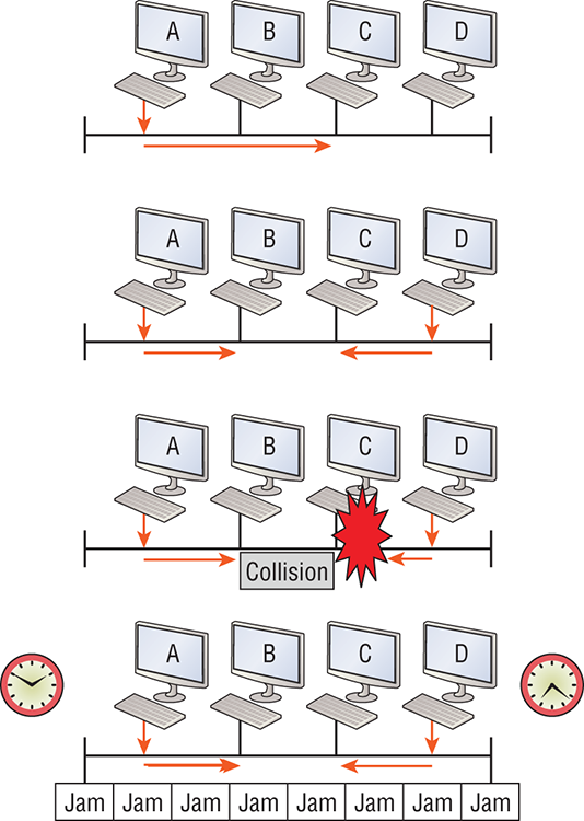
In Chapter 1, “Internetworking,” you learned that the Ethernet term collision domain refers to a network scenario wherein one device sends a frame out on a physical network segment forcing every other device on the same segment to pay attention to it. This is bad because if two devices on a single physical segment just happen to transmit simultaneously, it will cause a collision and require these devices to retransmit. Think of a collision event as a situation where each device’s digital signals totally interfere with one another on the wire. Figure 2-1 shows an old, legacy network that’s a single collision domain where only one host can transmit at a time.
Figure 2-1: Legacy collision domain design
The hosts connected to each hub are in the same collision domain, so if one of them transmits, all the others must take the time to listen for and read the digital signal. It is easy to see how collisions can be a serious drag on network performance, so I’ll show you how to strategically avoid them soon!
Okay—take another look at the network pictured in Figure 2-1. True, it has only one collision domain, but worse, it’s also a single broadcast domain—what a mess! Let’s check out an example, in Figure 2-2, of a typical network design still used today and see if it’s any better.
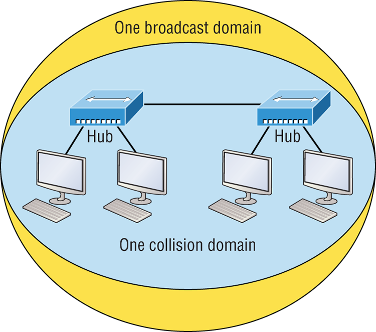
Figure 2-2: A typical network you’d see today
Because each port off a switch is a single collision domain, we gain more bandwidth for users, which is a great start. But switches don’t break up broadcast domains by default, so this is still only one broadcast domain, which is not so good. This can work in a really small network, but to expand it at all, we would need to break up the network into smaller broadcast domains or our users won’t get enough bandwidth! And you’re probably wondering about that device in the lower-right corner, right? Well, that’s a wireless access point, which is sometimes referred as an AP (which stands for access point). It’s a wireless device that allows hosts to connect wirelessly using the IEEE 802.11 specification and I added it to the figure to demonstrate how these devices can be used to extend a collision domain. But still, understand that APs don’t actually segment the network, they only extend them, meaning our LAN just got a lot bigger, with an unknown amount of hosts that are all still part of one measly broadcast domain! This clearly demonstrates why understanding exactly what a broadcast domain is, is so important, and now is a great time to talk about them in detail.
Broadcast Domain
Let me start by giving you the formal definition: broadcast domain refers to a group of devices on a specific network segment that hear all the broadcasts sent out on that specific network segment.
But even though a broadcast domain is usually a boundary delimited by physical media like switches and routers, it can also refer to a logical division of a network segment, where all hosts can communicate via a Data Link layer, hardware address broadcast.
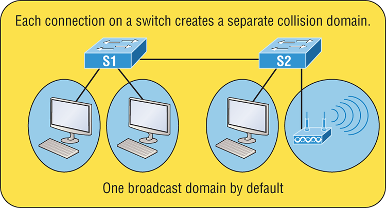
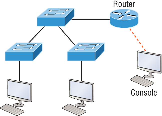
Figure 2-3 shows how a router would create a broadcast domain boundary.
Here you can see there are two router interfaces giving us two broadcast domains, and I count 10 switch segments, meaning we’ve got 10 collision domains.
The design depicted in Figure 2-3 is still in use today, and routers will be around for a long time, but in the latest, modern switched networks, it’s important to create small broadcast domains. We achieve this by building virtual LANs (VLANs) within our switched networks, which I’ll demonstrate shortly. Without employing VLANs in today’s switched environments, there wouldn’t be much bandwidth available to individual users. Switches break up collision domains with each port, which is awesome, but they’re still only one broadcast domain by default! It’s also one more reason why it’s extremely important to design our networks very carefully.
Figure 2-3: A router creates broadcast domain boundaries.
And key to carefully planning your network design is never to allow broadcast domains to grow too large and get out of control. Both collision and broadcast domains can easily be controlled with routers and VLANs, so there’s just no excuse to allow user bandwidth to slow to a painful crawl when there are plenty of tools in your arsenal to prevent the suffering!
An important reason for this book’s existence is to ensure that you really get the foundational basics of Cisco networks nailed down so you can affectively design, implement, configure, troubleshoot, and even dazzle colleagues and superiors with elegant designs that lavish your users with all the bandwidth their hearts could possibly desire.
To make it to the top of that mountain, you need more than just the basic story, so let’s move on to explore the collision detection mechanism used in half-duplex Ethernet.
CSMA/CD
Ethernet networking uses a protocol called Carrier Sense Multiple Access with Collision Detection (CSMA/CD), which helps devices share the bandwidth evenly while preventing two devices from transmitting simultaneously on the same network medium. CSMA/CD was actually created to overcome the problem of the collisions that occur when packets are transmitted from different nodes at the same time. And trust me—good collision management is crucial, because when a node transmits in a CSMA/CD network, all the other nodes on the network receive and examine that transmission. Only switches and routers can affectively prevent a transmission from propagating throughout the entire network!
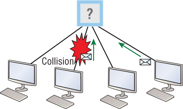
So, how does the CSMA/CD protocol work? Let’s start by taking a look at Figure 2-4.
Figure 2-4: CSMA/CD
When a host wants to transmit over the network, it first checks for the presence of a digital signal on the wire. If all is clear and no other host is transmitting, the host will then proceed with its transmission.
But it doesn’t stop there. The transmitting host constantly monitors the wire to make sure no other hosts begin transmitting. If the host detects another signal on the wire, it sends out an extended jam signal that causes all nodes on the segment to stop sending data—think busy signal.
The nodes respond to that jam signal by waiting a bit before attempting to transmit again. Backoff algorithms determine when the colliding stations can retransmit. If collisions keep occurring after 15 tries, the nodes attempting to transmit will then time out. Half-duplex can be pretty messy!
When a collision occurs on an Ethernet LAN, the following happens:
The ugly effects of having a CSMA/CD network sustain heavy collisions are delay, low throughput, and congestion.
At this point, let’s take a minute to talk about Ethernet in detail at both the Data Link layer (layer 2) and the Physical layer (layer 1).
Half- and Full-Duplex Ethernet
Half-duplex Ethernet is defined in the original IEEE 802.3 Ethernet specification, which differs a bit from how Cisco describes things. Cisco says Ethernet uses only one wire pair with a digital signal running in both directions on the wire. Even though the IEEE specifications discuss the half-duplex process somewhat differently, it’s not actually a full-blown technical disagreement. Cisco is really just talking about a general sense of what’s happening with Ethernet.
Half-duplex also uses the CSMA/CD protocol I just discussed to help prevent collisions and to permit retransmitting if one occurs. If a hub is attached to a switch, it must operate in half-duplex mode because the end stations must be able to detect collisions. Figure 2-5 shows a network with four hosts connected to a hub.
Figure 2-5: Half-duplex example
The problem here is that we can only run half-duplex, and if two hosts communicate at the same time there will be a collision. Also, half-duplex Ethernet is only about 30 to 40 percent efficient because a large 100Base-T network will usually only give you 30 to 40 Mbps, at most, due to overhead.
But full-duplex Ethernet uses two pairs of wires at the same time instead of a single wire pair like half-duplex. And full-duplex uses a point-to-point connection between the transmitter of the transmitting device and the receiver of the receiving device. This means that full-duplex data transfers happen a lot faster when compared to half-duplex transfers. Also, because the transmitted data is sent on a different set of wires than the received data, collisions won’t happen. Figure 2-6 shows four hosts connected to a switch, plus a hub, and definitely try not to use hubs if you can help it!
Figure 2-6: Full-duplex example
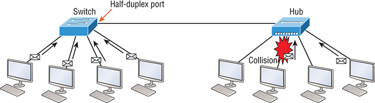
Theoretically all hosts connected to the switch in Figure 2-6 can communicate at the same time because they can run full-duplex. Just keep in mind that the switch port connecting to the hub as well as the hosts connecting to that hub must run at half-duplex.
The reason you don’t need to worry about collisions is because now it’s like a freeway with multiple lanes instead of the single-lane road provided by half-duplex. Full-duplex Ethernet is supposed to offer 100-percent efficiency in both directions—for example, you can get 20 Mbps with a 10 Mbps Ethernet running full-duplex, or 200 Mbps for Fast Ethernet. But this rate is known as an aggregate rate, which translates as “you’re supposed to get” 100 percent efficiency. No guarantees, in networking as in life!
You can use full-duplex Ethernet in at least the following six situations:
- With a connection from a switch to a host
- With a connection from a switch to a switch
- With a connection from a host to a host
- With a connection from a switch to a router
- With a connection from a router to a router
- With a connection from a router to a host
Now this may be a little confusing because this begs the question that if it’s capable of all that speed, why wouldn’t it actually deliver? Well, when a full-duplex Ethernet port is powered on, it first connects to the remote end and then negotiates with the other end of the Fast Ethernet link. This is called an auto-detect mechanism. This mechanism first decides on the exchange capability, which means it checks to see if it can run at 10, 100, or even 1000 Mbps. It then checks to see if it can run full-duplex, and if it can’t, it will run half-duplex.
Last, remember these important points:
- There are no collisions in full-duplex mode.
- A dedicated switch port is required for each full-duplex node.
- The host network card and the switch port must be capable of operating in full-duplex mode.
- The default behavior of 10Base-T and 100Base-T hosts is 10 Mbps half-duplex if the autodetect mechanism fails, so it is always good practice to set the speed and duplex of each port on a switch if you can.
Now let’s take a look at how Ethernet works at the Data Link layer.
Ethernet at the Data Link Layer
Ethernet at the Data Link layer is responsible for Ethernet addressing, commonly referred to as MAC or hardware addressing. Ethernet is also responsible for framing packets received from the Network layer and preparing them for transmission on the local network through the Ethernet contention-based media access method.
Ethernet Addressing
Here’s where we get into how Ethernet addressing works. It uses the Media Access Control (MAC) address burned into each and every Ethernet network interface card (NIC). The MAC, or hardware, address is a 48-bit (6-byte) address written in a hexadecimal format.
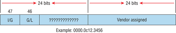
Figure 2-7 shows the 48-bit MAC addresses and how the bits are divided.
Figure 2-7: Ethernet addressing using MAC addresses
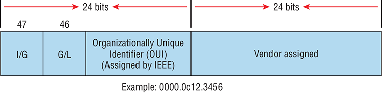
The organizationally unique identifier (OUI) is assigned by the IEEE to an organization. It’s composed of 24 bits, or 3 bytes, and it in turn assigns a globally administered address also made up of 24 bits, or 3 bytes, that’s supposedly unique to each and every adapter an organization manufactures. Surprisingly, there’s no guarantee when it comes to that unique claim! Okay, now look closely at the figure. The high-order bit is the Individual/Group (I/G) bit. When it has a value of 0, we can assume that the address is the MAC address of a device and that it may well appear in the source portion of the MAC header. When it’s a 1, we can assume that the address represents either a broadcast or multicast address in Ethernet.
The next bit is the global/local bit, sometimes called the G/L bit or U/L bit, where U means universal. When set to 0, this bit represents a globally administered address, as assigned by the IEEE, but when it’s a 1, it represents a locally governed and administered address. The low-order 24 bits of an Ethernet address represent a locally administered or manufacturer-assigned code. This portion commonly starts with 24 0s for the first card made and continues in order until there are 24 1s for the last (16,777,216th) card made. You’ll find that many manufacturers use these same six hex digits as the last six characters of their serial number on the same card.
Let’s stop for a minute and go over some addressing schemes important in the Ethernet world.
Binary to Decimal and Hexadecimal Conversion
Before we get into working with the TCP/IP protocol and IP addressing, which we’ll do in Chapter 3, “TCP/IP,” it’s really important for you to truly grasp the differences between binary, decimal, and hexadecimal numbers and how to convert one format into the other.
We’ll start with binary numbering, which is really pretty simple. The digits used are limited to either a 1 or a 0, and each digit is called a bit, which is short for binary digit. Typically, you group either 4 or 8 bits together, with these being referred to as a nibble and a byte, respectively.
The interesting thing about binary numbering is how the value is represented in a decimal format—the typical decimal format being the base-10 number scheme that we’ve all used since kindergarten. The binary numbers are placed in a value spot, starting at the right and moving left, with each spot having double the value of the previous spot.
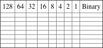
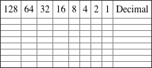
Table 2-1 shows the decimal values of each bit location in a nibble and a byte. Remember, a nibble is 4 bits and a byte is 8 bits.
Table 2-1: Binary values
| Nibble Values | Byte Values |
| 8 4 2 1 | 128 64 32 16 8 4 2 1 |
What all this means is that if a one digit (1) is placed in a value spot, then the nibble or byte takes on that decimal value and adds it to any other value spots that have a 1. If a zero (0) is placed in a bit spot, you don’t count that value.
Let me clarify this a little. If we have a 1 placed in each spot of our nibble, we would then add up 8 + 4 + 2 + 1 to give us a maximum value of 15. Another example for our nibble values would be 1001, meaning that the 8 bit and the 1 bit are turned on, which equals a decimal value of 9. If we have a nibble binary value of 0110, then our decimal value would be 6, because the 4 and 2 bits are turned on.
But the byte decimal values can add up to a number that’s significantly higher than 15. This is how: If we counted every bit as a one (1), then the byte binary value would look like the following example because, remember, 8 bits equal a byte:
We would then count up every bit spot because each is turned on. It would look like this, which demonstrates the maximum value of a byte:
There are plenty of other decimal values that a binary number can equal. Let’s work through a few examples:
Which bits are on? The 128, 16, 4, and 2 bits are on, so we’ll just add them up: 128 + 16 + 4 + 2 = 150.
Which bits are on? The 64, 32, 8, and 4 bits are on, so we just need to add them up: 64 + 32 + 8 + 4 = 108.
Which bits are on? The 128, 64, 32, and 8 bits are on, so just add the values up: 128 + 64 + 32 + 8 = 232.
I highly recommend that you memorize Table 2-2 before braving the IP sections in Chapter 3, “TCP/IP,” and Chapter 4, “Easy Subnetting”!
Table 2-2: Binary to decimal memorization chart
| Binary Value | Decimal Value |
| 10000000 | 128 |
| 11000000 | 192 |
| 11100000 | 224 |
| 11110000 | 240 |
| 11111000 | 248 |
| 11111100 | 252 |
| 11111110 | 254 |
| 11111111 | 255 |
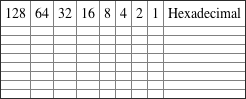
Hexadecimal addressing is completely different than binary or decimal—it’s converted by reading nibbles, not bytes. By using a nibble, we can convert these bits to hex pretty simply. First, understand that the hexadecimal addressing scheme uses only the characters 0 through 9. Because the numbers 10, 11, 12, and so on can’t be used (because they are two-digit numbers), the letters A, B, C, D, E, and F are used instead to represent 10, 11, 12, 13, 14, and 15, respectively.
Table 2-3 shows both the binary value and the decimal value for each hexadecimal digit.
Table 2-3: Hex to binary to decimal chart
| Hexadecimal Value | Binary Value | Decimal Value |
| 0 | 0000 | 0 |
| 1 | 0001 | 1 |
| 2 | 0010 | 2 |
| 3 | 0011 | 3 |
| 4 | 0100 | 4 |
| 5 | 0101 | 5 |
| 6 | 0110 | 6 |
| 7 | 0111 | 7 |
| 8 | 1000 | 8 |
| 9 | 1001 | 9 |
| A | 1010 | 10 |
| B | 1011 | 11 |
| C | 1100 | 12 |
| D | 1101 | 13 |
| E | 1110 | 14 |
| F | 1111 | 15 |
Did you notice that the first 10 hexadecimal digits (0–9) are the same value as the decimal values? If not, look again because this handy fact makes those values super easy to convert!
Okay, now suppose you have something like this: 0x6A. This is important because sometimes Cisco likes to put 0x in front of characters so you know that they are a hex value. It doesn’t have any other special meaning. So what are the binary and decimal values? All you have to remember is that each hex character is one nibble and that two hex characters joined together make a byte. To figure out the binary value, put the hex characters into two nibbles and then join them together into a byte. 6 = 0110; A, which is 10 in hex = 1010; so the complete byte would be 01101010.
To convert from binary to hex, just take the byte and break it into nibbles. Let me clarify this.
Say you have the binary number 01010101. First, break it into nibbles—0101 and 0101—with the value of each nibble being 5 since the 1 and 4 bits are on. This makes the hex answer 0x55. And in decimal format, the binary number is 01010101, which converts to 64 + 16 + 4 + 1 = 85.
Here’s another binary number:
Your answer would be 1100 = 12 and 1100 = 12, so therefore, it’s converted to CC in hex. The decimal conversion answer would be 128 + 64 + 8 + 4 = 204.
One more example, then we need to get working on the Physical layer. Suppose you had the following binary number:
The hex answer would be 0xB5, since 1011 converts to B and 0101 converts to 5 in hex value. The decimal equivalent is 128 + 32 + 16 + 4 + 1 = 181.
Ethernet Frames
The Data Link layer is responsible for combining bits into bytes and bytes into frames. Frames are used at the Data Link layer to encapsulate packets handed down from the Network layer for transmission on a type of media access.
The function of Ethernet stations is to pass data frames between each other using a group of bits known as a MAC frame format. This provides error detection from a cyclic redundancy check (CRC). But remember—this is error detection, not error correction. An example of a typical Ethernet frame used today is shown in Figure 2-8.
Figure 2-8: Typical Ethernet frame format
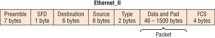
Following are the details of the various fields in the typical Ethernet frame type:
Let’s pause here for a minute and take a look at some frames caught on my trusty network analyzer. You can see that the frame below has only three fields: Destination, Source, and Type, which is shown as Protocol Type on this particular analyzer:
Destination:   00:60:f5:00:1f:27
Source:        00:60:f5:00:1f:2c
Protocol Type: 08-00 IP
This is an Ethernet_II frame. Notice that the Type field is IP, or 08-00, mostly just referred to as 0x800 in hexadecimal.
The next frame has the same fields, so it must be an Ethernet_II frame as well:
Destination:   ff:ff:ff:ff:ff:ff Ethernet Broadcast
Source:        02:07:01:22:de:a4
Protocol Type: 08-00 IP
Did you notice that this frame was a broadcast? You can tell because the destination hardware address is all 1s in binary, or all Fs in hexadecimal.
Let’s take a look at one more Ethernet_II frame. I’ll talk about this next example again when we use IPv6 in Chapter 14, “IPv6 Routing,” but you can see that the Ethernet frame is the same Ethernet_II frame used with the IPv4 routed protocol. The Type field has 0x86dd when the frame is carrying IPv6 data, and when we have IPv4 data, the frame uses 0x0800 in the protocol field:
Destination: IPv6-Neighbor-Discovery_00:01:00:03 (33:33:00:01:00:03)
Source: Aopen_3e:7f:dd (00:01:80:3e:7f:dd)
Type: IPv6 (0x86dd)
This is the beauty of the Ethernet_II frame. Because of the Type field, we can run any Network layer routed protocol and the frame will carry the data because it can identify the Network layer protocol!
Ethernet at the Physical Layer
Ethernet was first implemented by a group called DIX, which stands for Digital, Intel, and Xerox. They created and implemented the first Ethernet LAN specification, which the IEEE used to create the IEEE 802.3 committee. This was a 10 Mbps network that ran on coax and then eventually twisted-pair and fiber physical media.
The IEEE extended the 802.3 committee to three new committees known as 802.3u (Fast Ethernet), 802.3ab (Gigabit Ethernet on category 5) and then finally one more, 802.3ae (10 Gbps over fiber and coax). There are more standards evolving almost daily, such as the new 100 Gbps Ethernet (802.3ba)!
When designing your LAN, it’s really important to understand the different types of Ethernet media available to you. Sure, it would be great to run Gigabit Ethernet to each desktop and 10 Gbps between switches, but you would need to figure out how to justify the cost of that network today! However, if you mix and match the different types of Ethernet media methods currently available, you can come up with a cost-effective network solution that works really great.
The EIA/TIA (Electronic Industries Alliance and the newer Telecommunications Industry Association) is the standards body that creates the Physical layer specifications for Ethernet. The EIA/TIA specifies that Ethernet use a registered jack (RJ) connector on unshielded twisted-pair (UTP) cabling (RJ45). But the industry is moving toward simply calling this an 8-pin modular connector.
Every Ethernet cable type that’s specified by the EIA/TIA has inherent attenuation, which is defined as the loss of signal strength as it travels the length of a cable and is measured in decibels (dB). The cabling used in corporate and home markets is measured in categories. A higher-quality cable will have a higher-rated category and lower attenuation. For example, category 5 is better than category 3 because category 5 cables have more wire twists per foot and therefore less crosstalk. Crosstalk is the unwanted signal interference from adjacent pairs in the cable.
Here is a list of some of the most common IEEE Ethernet standards, starting with 10 Mbps Ethernet:

Armed with the basics covered so far in this chapter, you’re equipped to go to the next level and put Ethernet to work using various Ethernet cabling.
Ethernet Cabling
A discussion about Ethernet cabling is an important one, especially if you are planning on taking the Cisco exams. You need to really understand the following three types of cables:
- Straight-through cable
- Crossover cable
- Rolled cable
We will look at each in the following sections, but first, let’s take a look at the most common Ethernet cable used today, the category 5 Enhanced Unshielded Twisted Pair (UTP), shown in Figure 2-9.
Figure 2-9: Category 5 Enhanced UTP cable
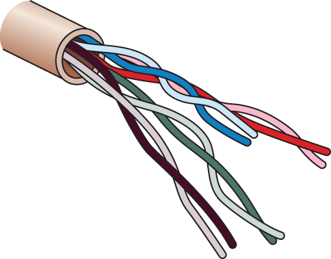
The category 5 Enhanced UTP cable can handle speeds up to a gigabit with a distance of up to 100 meters. Typically we’d use this cable for 100 Mbps and category 6 for a gigabit, but the category 5 Enhanced is rated for gigabit speeds and category 6 is rated for 10 Gbps!
Straight-Through Cable
The straight-through cable is used to connect the following devices:
- Host to switch or hub
- Router to switch or hub
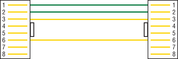
Four wires are used in straight-through cable to connect Ethernet devices. It’s relatively simple to create this type, and Figure 2-10 shows the four wires used in a straight-through Ethernet cable.
Figure 2-10: Straight-through Ethernet cable
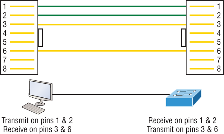
Notice that only pins 1, 2, 3, and 6 are used. Just connect 1 to 1, 2 to 2, 3 to 3, and 6 to 6 and you’ll be up and networking in no time. However, remember that this would be a 10/100 Mbps Ethernet-only cable and wouldn’t work with gigabit, voice, or other LAN or WAN technology.
Crossover Cable
The crossover cable can be used to connect the following devices:
- Switch to switch
- Hub to hub
- Host to host
- Hub to switch
- Router direct to host
- Router to router
The same four wires used in the straight-through cable are used in this cable—we just connect different pins together. Figure 2-11 shows how the four wires are used in a crossover Ethernet cable.
Figure 2-11: Crossover Ethernet cable
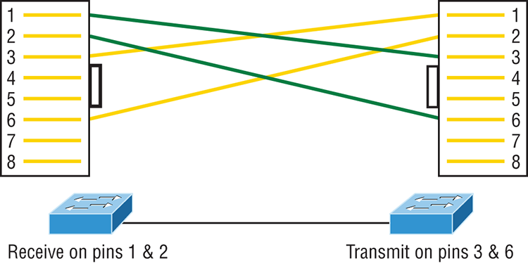
Notice that instead of connecting 1 to 1, 2 to 2, and so on, here we connect pins 1 to 3 and 2 to 6 on each side of the cable. Figure 2-12 shows some typical uses of straight-through and crossover cables.
Figure 2-12: Typical uses for straight-through and cross-over Ethernet cables
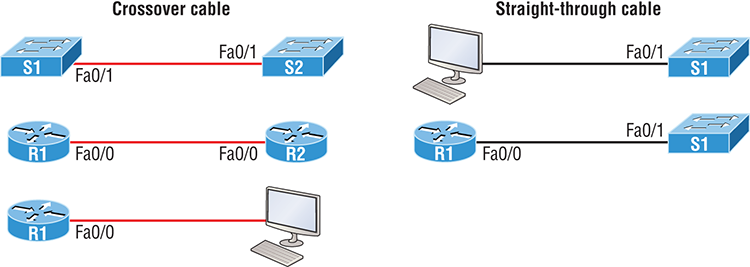
The crossover examples in Figure 2-12 are switch port to switch port, router Ethernet port to router Ethernet port, and PC Ethernet to router Ethernet port. For the straight-through examples I used PC Ethernet to switch port and router Ethernet port to switch port.
UTP Gigabit Wiring (1000Base-T)
In the previous examples of 10Base-T and 100Base-T UTP wiring, only two wire pairs were used, but that is not good enough for Gigabit UTP transmission.
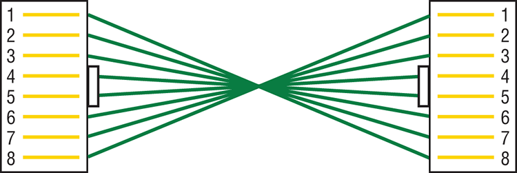
1000Base-T UTP wiring (Figure 2-13) requires four wire pairs and uses more advanced electronics so that each and every pair in the cable can transmit simultaneously. Even so, gigabit wiring is almost identical to my earlier 10/100 example, except that we’ll use the other two pairs in the cable.
Figure 2-13: UTP Gigabit crossover Ethernet cable
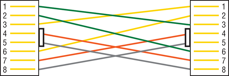
For a straight-through cable it’s still 1 to 1, 2 to 2, and so on up to pin 8. And in creating the gigabit crossover cable, you’d still cross 1 to 3 and 2 to 6, but you would add 4 to 7 and 5 to 8—pretty straightforward!
Rolled Cable
Although rolled cable isn’t used to connect any Ethernet connections together, you can use a rolled Ethernet cable to connect a host EIA-TIA 232 interface to a router console serial communication (COM) port.
If you have a Cisco router or switch, you would use this cable to connect your PC, Mac, or a device like an iPad to the Cisco hardware. Eight wires are used in this cable to connect serial devices, although not all eight are used to send information, just as in Ethernet networking. Figure 2-14 shows the eight wires used in a rolled cable.
Figure 2-14: Rolled Ethernet cable
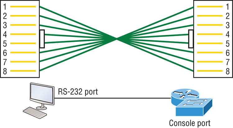
These are probably the easiest cables to make because you just cut the end off on one side of a straight-through cable, turn it over, and put it back on—with a new connector, of course!
Okay, once you have the correct cable connected from your PC to the Cisco router or switch console port, you can start your emulation program such as putty or SecureCRT to create a console connection and configure the device. Set the configuration as shown in Figure 2-15.
Figure 2-15: Configuring your console emulation program
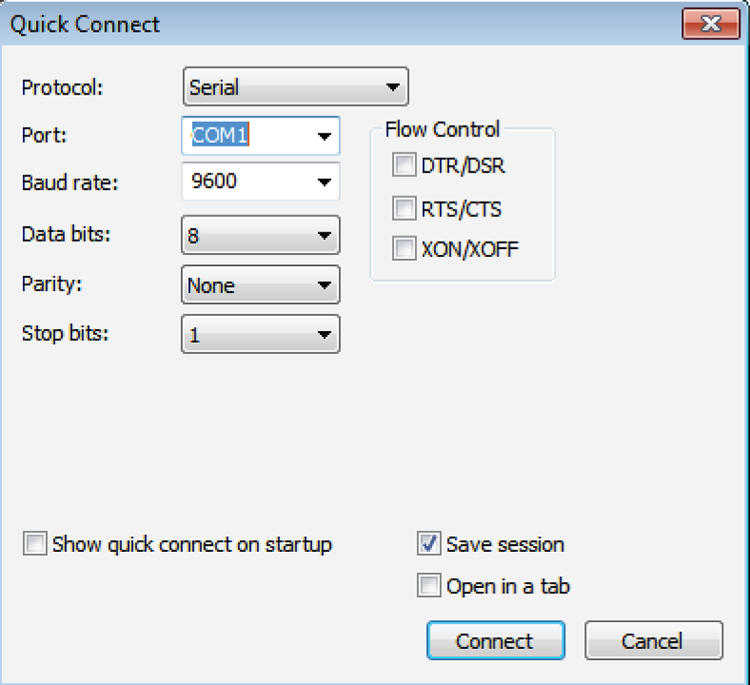
Notice that Bit Rate is set to 9600, Data Bits to 8, Parity to None, and Flow Control is set to None. At this point, you can click Connect and press the Enter key and you should be connected to your Cisco device console port.
Figure 2-16 shows a nice new 2960 switch with two console ports.
Figure 2-16: A Cisco 2960 console connections
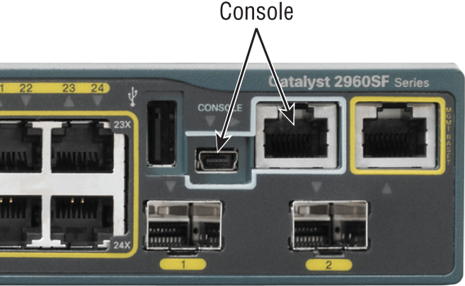
Notice there are two console connections on this new switch—a typical original RJ45 connection, and the newer mini type-B USB console. Remember that the new USB port supersedes the RJ45 port if you just happen to plug into both at the same time, and the USB port can have speeds up to 115,200 Kbps, which is awesome if you have to use Xmodem to update an IOS. I’ve even seen some cables that work on iPhones and iPads and allow them to connect to these mini USB ports!
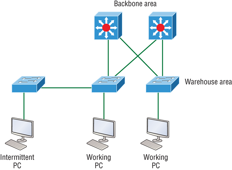
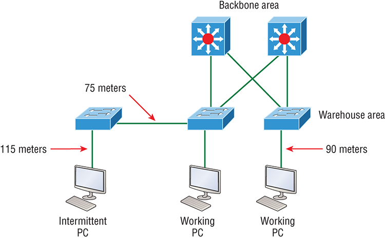
Now that you’ve seen the various RJ45 unshielded twisted-pair (UTP) cables, what type of cable is used between the switches in Figure 2-17?
Figure 2-17: RJ45 UTP cable question #1
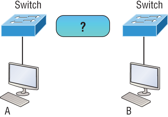
In order for host A to ping host B, you need a crossover cable to connect the two switches together. But what types of cables are used in the network shown in Figure 2-18?
Figure 2-18: RJ45 UTP cable question #2
In Figure 2-18, there’s a whole menu of cables in use. For the connection between the switches, we’d obviously use a crossover cable like we saw in Figure 2-13. The trouble is that you must understand that we have a console connection that uses a rolled cable. Plus, the connection from the router to the switch is a straight-through cable, as is true for the hosts to the switches. Keep in mind that if we had a serial connection, which we don’t, we would use a V.35 to connect us to a WAN.
Fiber Optic
Fiber-optic cabling has been around for a long time and has some solid standards. The cable allows for very fast transmission of data, is made of glass (or even plastic!), is very thin, and works as a waveguide to transmit light between two ends of the fiber. Fiber optics has been used to go very long distances, as in intercontinental connections, but it is becoming more and more popular in Ethernet LAN networks due to the fast speeds available and because, unlike UTP, it’s immune to interference like cross-talk.
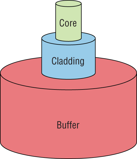
Some main components of this cable are the core and the cladding. The core will hold the light and the cladding confines the light in the core. The tighter the cladding, the smaller the core, and when the core is small, less light will be sent, but it can go faster and farther!
In Figure 2-19 you can see that there is a 9-micron core, which is very small and can be measured against a human hair, which is 50 microns.
Figure 2-19: Typical fiber cable
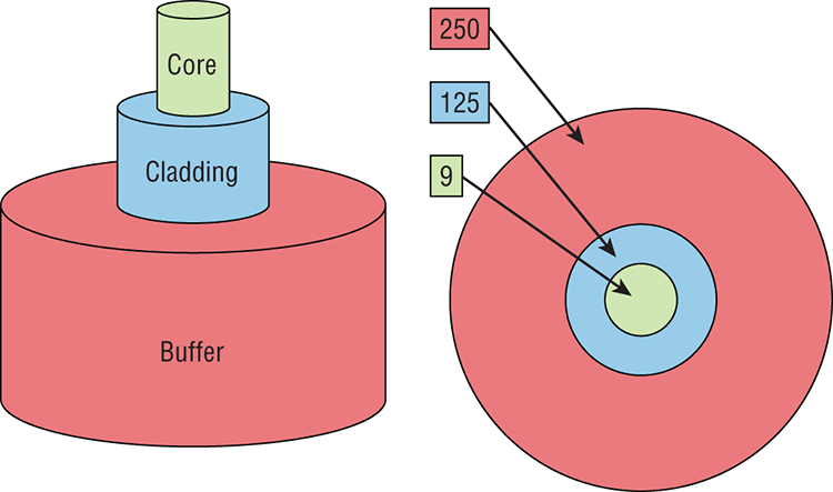
Dimensions are in um (10–6 meters). Not to scale.
The cladding is 125 microns, which is actually a fiber standard that allows manufacturers to make connectors for all fiber cables. The last piece of this cable is the buffer, which is there to protect the delicate glass.
There are two major types of fiber optics: single-mode and multimode. Figure 2-20 shows the differences between multimode and single-mode fibers.
Figure 2-20: Multimode and single-mode fibers
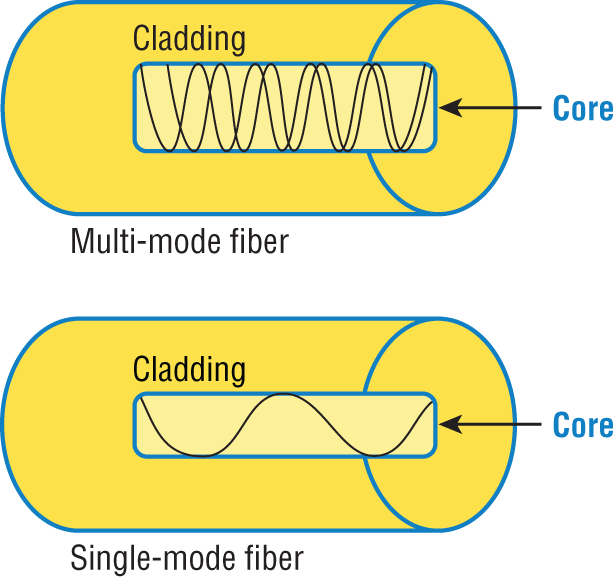
Single-mode is more expensive, has a tighter cladding, and can go much farther distances than multimode. The difference comes in the tightness of the cladding, which makes a smaller core, meaning that only one mode of light will propagate down the fiber. Multimode is looser and has a larger core so it allows multiple light particles to travel down the glass. These particles have to be put back together at the receiving end, so distance is less than that with single-mode fiber, which allows only very few light particles to travel down the fiber.
There are about 70 different connectors for fiber, and Cisco uses a few different types. Looking back at Figure 2-16, the two bottom ports are referred to as Small Form-Factor Pluggable, or SFPs.
Data Encapsulation
When a host transmits data across a network to another device, the data goes through a process called encapsulation and is wrapped with protocol information at each layer of the OSI model. Each layer communicates only with its peer layer on the receiving device.
To communicate and exchange information, each layer uses protocol data units (PDUs). These hold the control information attached to the data at each layer of the model. They are usually attached to the header in front of the data field but can also be at the trailer, or end, of it.
Each PDU attaches to the data by encapsulating it at each layer of the OSI model, and each has a specific name depending on the information provided in each header. This PDU information is read-only by the peer layer on the receiving device. After its read, it’s stripped off and the data is then handed to the next layer up.
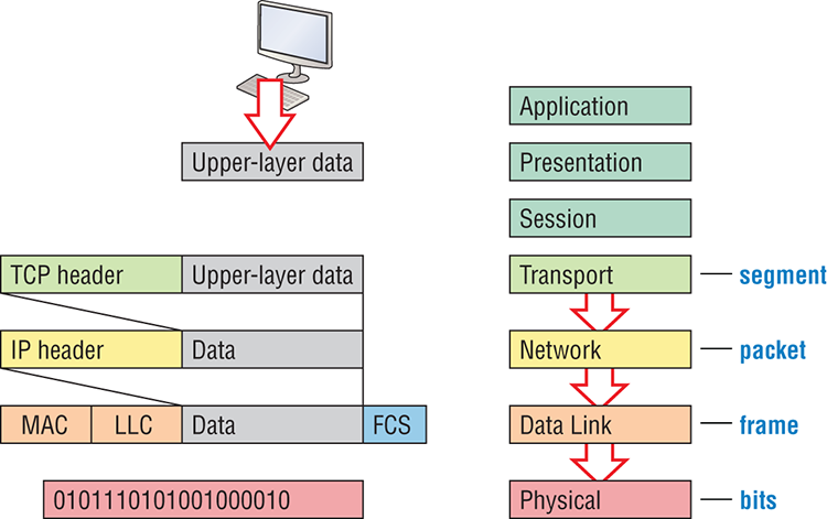
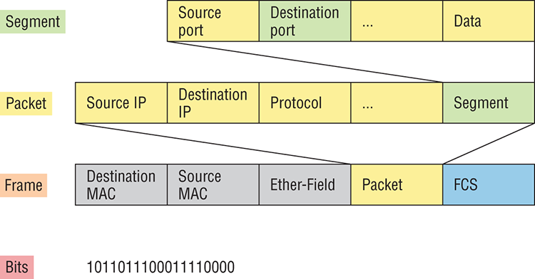
Figure 2-21 shows the PDUs and how they attach control information to each layer. This figure demonstrates how the upper-layer user data is converted for transmission on the network. The data stream is then handed down to the Transport layer, which sets up a virtual circuit to the receiving device by sending over a synch packet. Next, the data stream is broken up into smaller pieces, and a Transport layer header is created and attached to the header of the data field; now the piece of data is called a segment (a PDU). Each segment can be sequenced so the data stream can be put back together on the receiving side exactly as it was transmitted.
Each segment is then handed to the Network layer for network addressing and routing through the internetwork. Logical addressing (for example, IP and IPv6) is used to get each segment to the correct network. The Network layer protocol adds a control header to the segment handed down from the Transport layer, and what we have now is called a packet or datagram. Remember that the Transport and Network layers work together to rebuild a data stream on a receiving host, but it’s not part of their work to place their PDUs on a local network segment—which is the only way to get the information to a router or host.
It’s the Data Link layer that’s responsible for taking packets from the Network layer and placing them on the network medium (cable or wireless). The Data Link layer encapsulates each packet in a frame, and the frame’s header carries the hardware addresses of the source and destination hosts. If the destination device is on a remote network, then the frame is sent to a router to be routed through an internetwork. Once it gets to the destination network, a new frame is used to get the packet to the destination host.
Figure 2-21: Data encapsulation
To put this frame on the network, it must first be put into a digital signal. Since a frame is really a logical group of 1s and 0s, the physical layer is responsible for encoding these digits into a digital signal, which is read by devices on the same local network. The receiving devices will synchronize on the digital signal and extract (decode) the 1s and 0s from the digital signal. At this point, the devices reconstruct the frames, run a CRC, and then check their answer against the answer in the frame’s FCS field. If it matches, the packet is pulled from the frame and what’s left of the frame is discarded. This process is called de-encapsulation. The packet is handed to the Network layer, where the address is checked. If the address matches, the segment is pulled from the packet and what’s left of the packet is discarded. The segment is processed at the Transport layer, which rebuilds the data stream and acknowledges to the transmitting station that it received each piece. It then happily hands the data stream to the upper-layer application.
At a transmitting device, the data encapsulation method works like this:
To explain this in more detail using the layer addressing, I’ll use Figure 2-22.
Figure 2-22: PDU and layer addressing
Remember that a data stream is handed down from the upper layer to the Transport layer. As technicians, we really don’t care who the data stream comes from because that’s really a programmer’s problem. Our job is to rebuild the data stream reliably and hand it to the upper layers on the receiving device.
Before we go further in our discussion of Figure 2-22, let’s discuss port numbers and make sure you understand them. The Transport layer uses port numbers to define both the virtual circuit and the upper-layer processes, as you can see from Figure 2-23.
Figure 2-23: Port numbers at the Transport layer
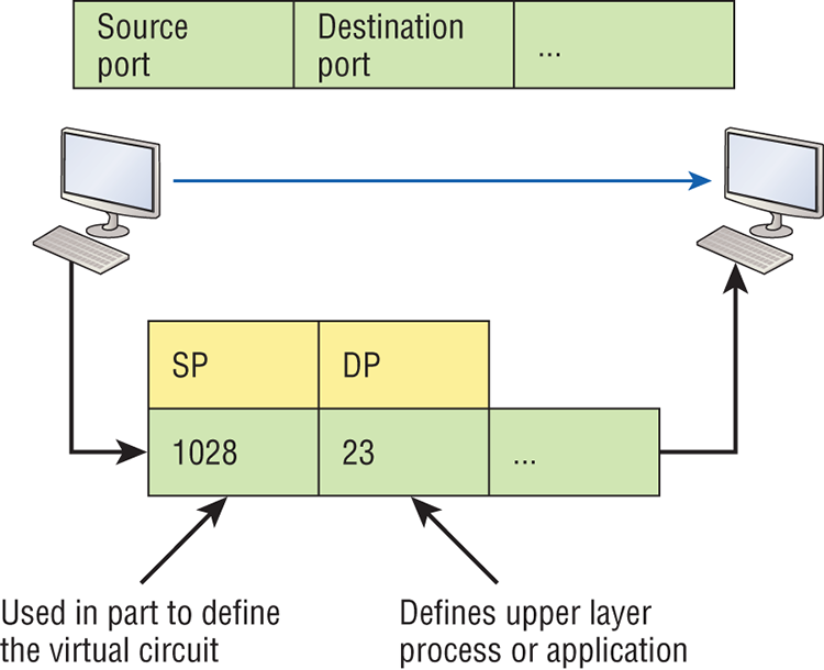
When using a connection-oriented protocol like TCP, the Transport layer takes the data stream, makes segments out of it, and establishes a reliable session by creating a virtual circuit. It then sequences (numbers) each segment and uses acknowledgments and flow control. If you’re using TCP, the virtual circuit is defined by the source and destination port number plus the source and destination IP address and called a socket. Understand that the host just makes this up, starting at port number 1024 because 0 through 1023 are reserved for well-known port numbers. The destination port number defines the upper-layer process or application that the data stream is handed to when the data stream is reliably rebuilt on the receiving host.
Now that you understand port numbers and how they are used at the Transport layer, let’s go back to Figure 2-22. Once the Transport layer header information is added to the piece of data, it becomes a segment that’s handed down to the Network layer along with the destination IP address. As you know, the destination IP address was handed down from the upper layers to the Transport layer with the data stream and was identified via name resolution at the upper layers—probably with DNS.
The Network layer adds a header and adds the logical addressing such as IP addresses to the front of each segment. Once the header is added to the segment, the PDU is called a packet. The packet has a protocol field that describes where the segment came from (either UDP or TCP) so it can hand the segment to the correct protocol at the Transport layer when it reaches the receiving host.
The Network layer is responsible for finding the destination hardware address that dictates where the packet should be sent on the local network. It does this by using the Address Resolution Protocol (ARP)—something I’ll talk about more in Chapter 3. IP at the Network layer looks at the destination IP address and compares that address to its own source IP address and subnet mask. If it turns out to be a local network request, the hardware address of the local host is requested via an ARP request. If the packet is destined for a remote host, IP will look for the IP address of the default gateway (router) instead.
The packet, along with the destination hardware address of either the local host or default gateway, is then handed down to the Data Link layer. The Data Link layer will add a header to the front of the packet and the piece of data then becomes a frame. It’s called a frame because both a header and a trailer are added to the packet, which makes it look like it’s within bookends—a frame—as shown in Figure 2-22. The frame uses an Ether-Type field to describe which protocol the packet came from at the Network layer. Now a cyclic redundancy check is run on the frame, and the answer to the CRC is placed in the Frame Check Sequence field found in the trailer of the frame.
The frame is now ready to be handed down, one bit at a time, to the Physical layer, which will use bit-timing rules to encode the data in a digital signal. Every device on the network segment will receive the digital signal and synchronize with the clock and extract the 1s and 0s from the digital signal to build a frame. After the frame is rebuilt, a CRC is run to make sure the frame is in proper order. If everything turns out to be all good, the hosts will check the destination MAC and IP addresses to see if the frame is for them.
If all this is making your eyes cross and your brain freeze, don’t freak. I’ll be going over exactly how data is encapsulated and routed through an internetwork later, in Chapter 8, “IP Routing.”
The Cisco Three-Layer Hierarchical Model
Most of us were exposed to hierarchy early in life. Anyone with older siblings learned what it was like to be at the bottom of the hierarchy. Regardless of where you first discovered the concept of hierarchy, most of us experience it in many aspects of our lives. It’s hierarchy that helps us understand where things belong, how things fit together, and what functions go where. It brings order to otherwise complex models. If you want a pay raise, for instance, hierarchy dictates that you ask your boss, not your subordinate, because that’s the person whose role it is to grant or deny your request. So basically, understanding hierarchy helps us discern where we should go to get what we need.
Hierarchy has many of the same benefits in network design that it does in other areas of life. When used properly, it makes networks more predictable and helps us define which areas should perform certain functions. Likewise, you can use tools such as access lists at certain levels in hierarchical networks and avoid them at others.
Let’s face it: Large networks can be extremely complicated, with multiple protocols, detailed configurations, and diverse technologies. Hierarchy helps us summarize a complex collection of details into an understandable model, bringing order from the chaos. Then, as specific configurations are needed, the model dictates the appropriate manner in which to apply them.
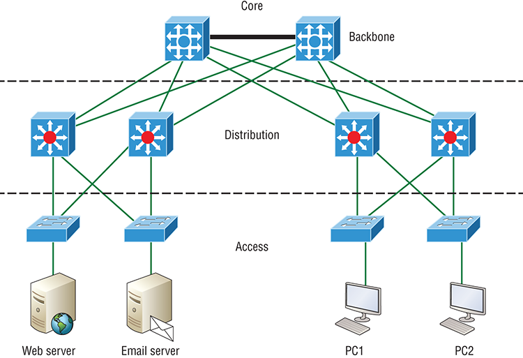
The Cisco hierarchical model can help you design, implement, and maintain a scalable, reliable, cost-effective hierarchical internetwork. Cisco defines three layers of hierarchy, as shown in Figure 2-24, each with specific functions.
Each layer has specific responsibilities. Keep in mind that the three layers are logical and are not necessarily physical devices. Consider the OSI model, another logical hierarchy. Its seven layers describe functions but not necessarily protocols, right? Sometimes a protocol maps to more than one layer of the OSI model, and sometimes multiple protocols communicate within a single layer. In the same way, when we build physical implementations of hierarchical networks, we may have many devices in a single layer, or there may be a single device performing functions at two layers. Just remember that the definition of the layers is logical, not physical!
So let’s take a closer look at each of the layers now.
The Core Layer
The core layer is literally the core of the network. At the top of the hierarchy, the core layer is responsible for transporting large amounts of traffic both reliably and quickly. The only purpose of the network’s core layer is to switch traffic as fast as possible. The traffic transported across the core is common to a majority of users. But remember that user data is processed at the distribution layer, which forwards the requests to the core if needed.
Figure 2-24: The Cisco hierarchical model
If there’s a failure in the core, every single user can be affected! This is why fault tolerance at this layer is so important. The core is likely to see large volumes of traffic, so speed and latency are driving concerns here. Given the function of the core, we can now consider some design specifics. Let’s start with some things we don’t want to do:
- Never do anything to slow down traffic. This includes using access lists, routing between virtual local area networks and implementing packet filtering.
- Don’t support workgroup access here.
- Avoid expanding the core (e.g., adding routers when the internetwork grows). If performance becomes an issue in the core, give preference to upgrades over expansion.
Here’s a list of things that we want to achieve as we design the core:
- Design the core for high reliability. Consider data-link technologies that facilitate both speed and redundancy, like Gigabit Ethernet with redundant links or even 10 Gigabit Ethernet.
- Design with speed in mind. The core should have very little latency.
- Select routing protocols with lower convergence times. Fast and redundant data-link connectivity is no help if your routing tables are shot!
The Distribution Layer
The distribution layer is sometimes referred to as the workgroup layer and is the communication point between the access layer and the core. The primary functions of the distribution layer are to provide routing, filtering, and WAN access and to determine how packets can access the core, if needed. The distribution layer must determine the fastest way that network service requests are handled—for example, how a file request is forwarded to a server. After the distribution layer determines the best path, it forwards the request to the core layer if necessary. The core layer then quickly transports the request to the correct service.
The distribution layer is where we want to implement policies for the network because we are allowed a lot of flexibility in defining network operation here. There are several things that should generally be handled at the distribution layer:
- Routing
- Implementing tools (such as access lists), packet filtering, and queuing
- Implementing security and network policies, including address translation and firewalls
- Redistributing between routing protocols, including static routing
- Routing between VLANs and other workgroup support functions
- Defining broadcast and multicast domains
Key things to avoid at the distribution layer are those that are limited to functions that exclusively belong to one of the other layers!
The Access Layer
The access layer controls user and workgroup access to internetwork resources. The access layer is sometimes referred to as the desktop layer. The network resources most users need will be available locally because the distribution layer handles any traffic for remote services. The following are some of the functions to be included at the access layer:
- Continued (from distribution layer) use of access control and policies
- Creation of separate collision domains (segmentation)
- Workgroup connectivity into the distribution layer
Technologies like Gigabit or Fast Ethernet switching are frequently seen in the access layer.
I can’t stress this enough—just because there are three separate levels does not imply three separate devices! There could be fewer or there could be more. After all, this is a layered approach.
Summary
In this chapter, you learned the fundamentals of Ethernet networking, how hosts communicate on a network. You discovered how CSMA/CD works in an Ethernet half-duplex network.
I also talked about the differences between half- and full-duplex modes, and we discussed the collision detection mechanism called CSMA/CD.
I described the common Ethernet cable types used in today’s networks in this chapter as well, and by the way, you’d be wise to study that section really well!
Important enough to not gloss over, this chapter provided an introduction to encapsulation. Encapsulation is the process of encoding data as it goes down the OSI stack.
Last, I covered the Cisco three-layer hierarchical model. I described in detail the three layers and how each is used to help design and implement a Cisco internetwork.
Exam Essentials
Written Labs
In this section, you’ll complete the following labs to make sure you’ve got the information and concepts contained within them fully dialed in:
The answers to these labs can be found in Appendix A, “Answers to Written Labs.”
Written Lab 2.1: Binary/Decimal/Hexadecimal Conversion
1. Convert from decimal IP address to binary format.


2. Convert the following from binary format to decimal IP address.


Written Lab 2.2: CSMA/CD Operations
Carrier Sense Multiple Access with Collision Detection (CSMA/CD) helps to minimize collisions in the network, thereby increasing data transmission efficiency. Place the following steps of its operation in the order in which they occur.
- All hosts have equal priority to transmit after the timers have expired.
- Each device on the Ethernet segment stops transmitting for a short time until the timers expire.
- The collision invokes a random backoff algorithm.
- A jam signal informs all devices that a collision occurred.
Written Lab 2.3: Cabling
For each of the following situations, determine whether a straight-through, crossover, or rolled cable would be used.
Written Lab 2.4: Encapsulation
Place the following steps of the encapsulation process in the proper order.
- Packets or datagrams are converted to frames for transmission on the local network. Hardware (Ethernet) addresses are used to uniquely identify hosts on a local network segment.
- Segments are converted to packets or datagrams, and a logical address is placed in the header so each packet can be routed through an internetwork.
- User information is converted to data for transmission on the network.
- Frames are converted to bits, and a digital encoding and clocking scheme is used.
- Data is converted to segments, and a reliable connection is set up between the transmitting and receiving hosts.
Review Questions
The answers to these questions can be found in Appendix B, “Answers to Chapter Review Questions.”
1. In the accompanying graphic, what is the name for the section of the MAC address marked as unknown?
A. IOS
B. OSI
C. ISO
D. OUI
2. _____________on an Ethernet network is the retransmission delay that’s enforced when a collision occurs.
A. Backoff
B. Carrier sense
C. Forward delay
D. Jamming
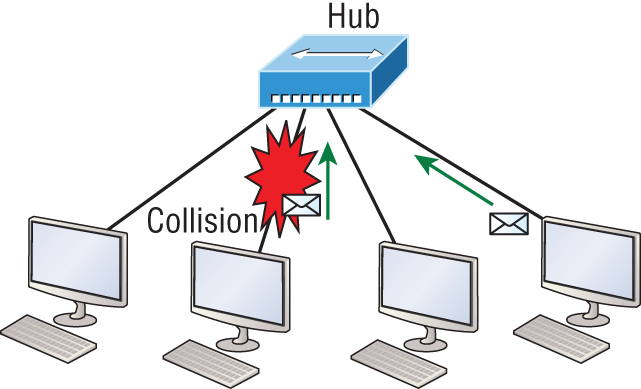
3. On which type of device could the situation shown in the diagram occur?
A. Hub
B. Switch
C. Router
D. Bridge
4. In the Ethernet II frame shown here, what is the function of the section labeled “FCS”?
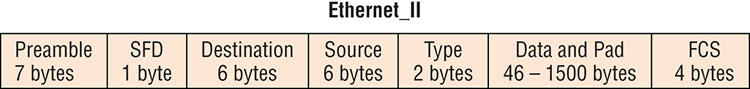
A. Allows the receiving devices to lock the incoming bit stream.
B. Error detection
C. Identifies the upper-layer protocol
D. Identifies the transmitting device
5. The contention method used by Ethernet is called ____________.
A. Token passing
B. CSMA/CD
C. Polling
D. CSMA/CA
6. In which if the following situations can you not use full-duplex?
A. With a connection from a switch to a switch
B. With a connection from a router to a router
C. With a connection from a host to a host
D. With a connection from a host to a hub
7. Between which systems could you use a cable that uses the pinout pattern shown below?
A. With a connection from a switch to a switch
B. With a connection from a router to a router
C. With a connection from a host to a host
D. With a connection from a host to a switch
8. When the I/G bit in a MAC address is set to 1 the transmission is ____________. (Choose all that apply.)
A. Unicast
B. Broadcast
C. Multicast
D. Anycast
9. What type of cable uses the pinout shown here?

A. Fiber optic
B. Crossover Gigabit Ethernet cable
C. Straight-through FastEthernet
D. Coaxial
10. When configuring a terminal emulation program which of the following is an incorrect setting?
A. Bit rate: 9600
B. Parity: None
C. Flow control: None
D. Data bits: 1
11. Which part of a MAC address indicates whether the address is a locally or globally administered address?
A. FCS
B. I/G bit
C. OUI
D. U/L bit
12. What cable type uses the pinout arrangement shown below?
A. Fiber optic
B. Rolled
C. Straight through
D. Crossover
13. Which of the following is not one of the actions taken in the operation of CSMA/CD when a collision occurs?
A. A jam signal informs all devices that a collision occurred.
B. The collision invokes a random backoff algorithm on the systems involved in the collision.
C. Each device on the Ethernet segment stops transmitting for a short time until their backoff timers expire.
D. All hosts have equal priority to transmit after the timers have expired.
14. Which of the following statements is false with regard to Ethernet?
A. There are very few collisions in full-duplex mode.
B. A dedicated switch port is required for each full-duplex node.
C. The host network card and the switch port must be capable of operating in full-duplex mode to use full-duplex.
D. The default behavior of 10Base-T and 100Base-T hosts is 10 Mbps half-duplex if the autodetect mechanism fails.
15. In the diagram below, identify the cable types required for connections A and B.
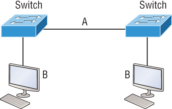
A. A crossover, B crossover
B. A crossover, B straight through
C. A straight through, B straight through
D. A straight through, B crossover
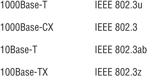
16. In the work area below match the cable type to the standard with which it goes.
17. The cable used to connect to the console port on a router or switch is called a __________ cable.
A. Crossover
B. Rollover
C. Straight-through
D. Full-duplex
18. Which of the following items comprise a socket?
A. IP address and MAC address
B. IP address and port number
C. Port number and MAC address
D. MAC address and DLCI
19. Which of the following hexadecimal numbers converts to 28 in decimal?
A. 1c
B. 12
C. 15
D. ab
20. What cable type is shown in the below graphic?
A. Fiber optic
B. Rollover
C. Coaxial
D. Full-duplex