Chapter 8
IP Routing
The following ICND1 exam topics are covered in this chapter:
- IP Routing Technologies
- Describe basic routing concepts
- CEF
- Packet forwarding
- Router lookup process
- Configure and verify routing configuration for a static or default route given specific routing requirements
- Differentiate methods of routing and routing protocols
- Static vs. Dynamic
- Link State vs. Distance Vector
- next hop
- ip routing table
- Passive interfaces
It’s time now to turn our focus toward the core topic of the ubiquitous IP routing process. It’s integral to networking because it pertains to all routers and configurations that use it, which is easily the lion’s share. IP routing is basically the process of moving packets from one network to another network using routers. And by routers I mean Cisco routers, of course! However, the terms router and layer 3 device are interchangeable, and throughout this chapter when I use the term router, I am referring to any layer 3 device.
Before jumping into this chapter, I want to make sure you understand the difference between a routing protocol and a routed protocol. Routers use routing protocols to dynamically find all networks within the greater internetwork and to ensure that all routers have the same routing table. Routing protocols are also employed to determine the best path a packet should take through an internetwork to get to its destination most efficiently. RIP, RIPv2, EIGRP, and OSPF are great examples of the most common routing protocols.
Once all routers know about all networks, a routed protocol can be used to send user data (packets) through the established enterprise. Routed protocols are assigned to an interface and determine the method of packet delivery. Examples of routed protocols are IP and IPv6.
I’m going to discuss the RIP routing protocol in this chapter even though I know that it isn’t included in any objective. We’ll cover it anyway because it will help you gain a solid understanding of the routing process before we get into a study on the much more complex OSPF protocol in the next chapter. We’ll also discuss RIP because you just never know when Cisco will toss in exam questions that include topics they haven’t bothered to list as a bona fide objective either! So even though I want you to be prepared just in case, I’ll promise to keep the RIP section reasonably short.
I’m pretty confident I don’t have to underscore how crucial it is for you have this chapter’s material down to a near instinctive level. IP routing is innately what Cisco routers do, and they do it very well, so having a firm grasp of the fundamentals and basics of this topic are vital if you want to excel during the exam and in a real-world networking environment as well!
In this chapter, I’m going to show you how to configure and verify IP routing with Cisco routers and guide you through these five key subjects:
- Routing basics
- The IP routing process
- Static routing
- Default routing
- Dynamic routing
We’ll get into more the advanced aspects of dynamic routing next in Chapter 9, “Open Shortest Path First (OSPF).” But first, I want to nail down the basics of how packets actually move through an internetwork, so let’s get started!
Routing Basics
Once you create an internetwork by connecting your WANs and LANs to a router, you’ll need to configure logical network addresses, like IP addresses, to all hosts on that internetwork for them to communicate successfully throughout it.
The term routing refers to taking a packet from one device and sending it through the network to another device on a different network. Routers don’t really care about hosts—they only care about networks and the best path to each one of them. The logical network address of the destination host is key to get packets through a routed network. It’s the hardware address of the host that’s used to deliver the packet from a router and ensure it arrives at the correct destination host.
Routing is irrelevant if your network has no routers because their job is to route traffic to all the networks in your internetwork, but this is rarely the case! So here’s an important list of the minimum factors a router must know to be able to affectively route packets:
- Destination address
- Neighbor routers from which it can learn about remote networks
- Possible routes to all remote networks
- The best route to each remote network
- How to maintain and verify routing information
The router learns about remote networks from neighboring routers or from an administrator. The router then builds a routing table, which is basically a map of the internetwork, and it describes how to find remote networks. If a network is directly connected, then the router already knows how to get to it.
But if a network isn’t directly connected to the router, the router must use one of two ways to learn how to get to the remote network. The static routing method requires someone to hand-type all network locations into the routing table, which can be a pretty daunting task when used on all but the smallest of networks!
Conversely, when dynamic routing is used, a protocol on one router communicates with the same protocol running on neighboring routers. The routers then update each other about all the networks they know about and place this information into the routing table. If a change occurs in the network, the dynamic routing protocols automatically inform all routers about the event. If static routing is used, the administrator is responsible for updating all changes by hand onto all routers. Most people usually use a combination of dynamic and static routing to administer a large network.
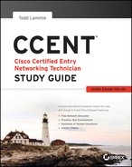
Before we jump into the IP routing process, let’s take a look at a very simple example that demonstrates how a router uses the routing table to route packets out of an interface. We’ll be going into a more detailed study of the process soon, but I want to show you something called the “longest match rule” first. With it, IP will scan a routing table to find the longest match as compared to the destination address of a packet. Let’s take a look at Figure 8-1 to get a picture of this process.
Figure 8-1: A simple routing example
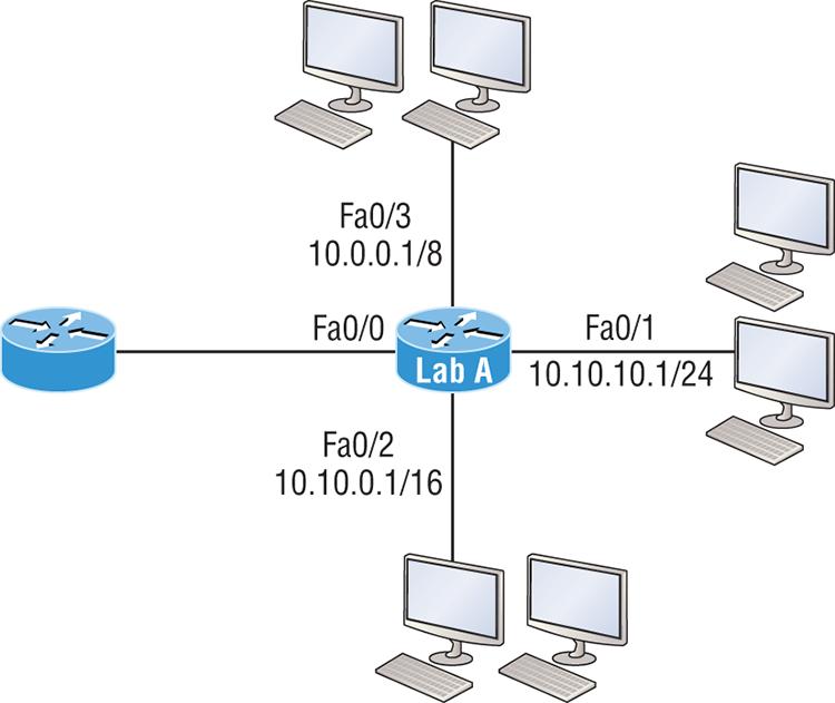
Figure 8-1 shows a simple network. Lab_A has four interfaces. Can you see which interface will be used to forward an IP datagram to a host with a destination IP address of 10.10.10.30?
By using the command show ip route on a router, we can see the routing table (map of the internetwork) that Lab_A has used to make its forwarding decisions:
Lab_A#sh ip route
Codes: L - local, C - connected, S - static,
[output cut]
        10.0.0.0/8 is variably subnetted, 6 subnets, 4 masks
C       10.0.0.0/8 is directly connected, FastEthernet0/3
L       10.0.0.1/32 is directly connected, FastEthernet0/3
C       10.10.0.0/16 is directly connected, FastEthernet0/2
L       10.10.0.1/32 is directly connected, FastEthernet0/2
C       10.10.10.0/24 is directly connected, FastEthernet0/1
L       10.10.10.1/32 is directly connected, FastEthernet0/1
S*      0.0.0.0/0 is directly connected, FastEthernet0/0
The C in the routing table output means that the networks listed are “directly connected,” and until we add a routing protocol like RIPv2, OSPF, etc. to the routers in our internetwork, or enter static routes, only directly connected networks will show up in our routing table. But wait—what about that L in the routing table—that’s new, isn’t it? Yes it is, because in the new Cisco IOS 15 code, Cisco defines a different route, called a local route. Each has a /32 prefix defining a route just for the one address. So in this example, the router has relied upon these routes that list their own local IP addresses to more efficiently forward packets to the router itself.
So let’s get back to the original question: By looking at the figure and the output of the routing table, can you determine what IP will do with a received packet that has a destination IP address of 10.10.10.30? The answer is that the router will packet-switch the packet to interface FastEthernet 0/1, which will frame the packet and then send it out on the network segment. Based upon the longest match rule, IP would look for 10.10.10.30, and if that isn’t found in the table, then IP would search for 10.10.10.0, then 10.10.0.0, and so on until a route is discovered.
Here’s another example: Based on the output of the next routing table, which interface will a packet with a destination address of 10.10.10.14 be forwarded from?
Lab_A#sh ip route
[output cut]
Gateway of last resort is not set
C      10.10.10.16/28 is directly connected, FastEthernet0/0
L      10.10.10.17/32 is directly connected, FastEthernet0/0
C      10.10.10.8/29 is directly connected, FastEthernet0/1
L      10.10.10.9/32 is directly connected, FastEthernet0/1
C      10.10.10.4/30 is directly connected, FastEthernet0/2
L      10.10.10.5/32 is directly connected, FastEthernet0/2
C      10.10.10.0/30 is directly connected, Serial 0/0
L      10.10.10.1/32 is directly connected, Serial0/0
To figure this out, look closely at the output until you see that the network is subnetted and each interface has a different mask. And I have to tell you—you just can’t answer this question if you can’t subnet! 10.10.10.14 would be a host in the 10.10.10.8/29 subnet that’s connected to the FastEthernet0/1 interface. Don’t freak if you’re struggling and don’t get this! Instead, just go back and reread Chapter 4, “Easy Subnetting,” until it becomes clear to you.
The IP Routing Process
The IP routing process is fairly simple and doesn’t change, regardless of the size of your network. For a good example of this fact, I’ll use Figure 8-2 to describe step-by-step what happens when Host_A wants to communicate with Host_B on a different network.
Figure 8-2: IP routing example using two hosts and one router
In Figure 8-2 a user on Host_A pinged Host_B’s IP address. Routing doesn’t get any simpler than this, but it still involves a lot of steps, so let’s work through them now:
C:>arp -a
Interface: 172.16.10.2 --- 0x3
  Internet Address      Physical Address      Type
172.16.10.1 00-15-05-06-31-b0 dynamicFigure 8-3: Frame used from Host_A to the Lab_A router when Host_B is pinged

- If the CRC matches, then the hardware destination address is checked to see if it matches (which, in this example, is the router’s interface Ethernet 0).
- If it’s a match, then the Ether-Type field is checked to find the protocol used at the Network layer.
Lab_A>sh ip route
C       172.16.10.0 is directly connected,    Ethernet0
L       172.16.10.1/32 is directly connected, Ethernet0
C       172.16.20.0 is directly connected,    Ethernet1
L 172.16.20.1/32 is directly connected, Ethernet1- If the hardware address of Host_B has already been resolved and is in the router’s ARP cache, then the packet and the hardware address will be handed down to the Data Link layer to be framed. Let’s take a look at the ARP cache on the Lab_A router by using the show ip arp command:
Lab_A#sh ip arp
Protocol  Address     Age(min) Hardware Addr  Type   Interface
Internet  172.16.20.1   -     00d0.58ad.05f4  ARPA   Ethernet1
Internet  172.16.20.2   3     0030.9492.a5dd  ARPA   Ethernet1
Internet  172.16.10.1   -     00d0.58ad.06aa  ARPA   Ethernet0
Internet 172.16.10.2 12 0030.9492.a4ac ARPA Ethernet0- Now if the hardware address hasn’t already been resolved, the router will send an ARP request out E1 looking for the 172.16.20.2 hardware address. Host_B responds with its hardware address, and the packet and destination hardware addresses are then both sent to the Data Link layer for framing.
- The destination and source hardware addresses
- The Ether-Type field with 0x0800 (IP) in it
- The FCS field with the CRC result in tow

You’ve just experienced Todd’s 36 easy steps to understanding IP routing. The key point here is that if you had a much larger network, the process would be the same. It’s just that the larger the internetwork, the more hops the packet goes through before it finds the destination host.
It’s super-important to remember that when Host_A sends a packet to Host_B, the destination hardware address used is the default gateway’s Ethernet interface. Why? Because frames can’t be placed on remote networks—only local networks. So packets destined for remote networks must go through the default gateway.
Let’s take a look at Host_A’s ARP cache now:
C: >arp -a
Interface: 172.16.10.2 --- 0x3
  Internet Address      Physical Address      Type
  172.16.10.1           00-15-05-06-31-b0     dynamic
  172.16.20.1           00-15-05-06-31-b0     dynamic
Did you notice that the hardware (MAC) address that Host_A uses to get to Host_B is the Lab_A E0 interface? Hardware addresses are always local, and they never pass through a router’s interface. Understanding this process is as important as air to you, so carve this into your memory!
The Cisco Router Internal Process
One more thing before we get to testing your understanding of my 36 steps of IP routing. I think it’s important to explain how a router forwards packets internally. For IP to look up a destination address in a routing table on a router, processing in the router must take place, and if there are tens of thousands of routes in that table, the amount of CPU time would be enormous. It results in a potentially overwhelming amount of overhead—think about a router at your ISP that has to calculate millions of packets per second and even subnet to find the correct exit interface! Even with the little network I’m using in this book, lots of processing would need to be done if there were actual hosts connected and sending data.
Cisco uses three types of packet-forwarding techniques.
Testing Your IP Routing Understanding
Since understanding IP routing is super-important, it’s time for that little test I talked about earlier on how well you’ve got the IP routing process down so far. I’m going to do that by having you look at a couple of figures and answer some very basic IP routing questions based upon them.
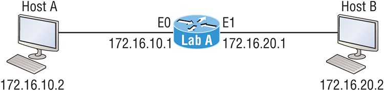
Figure 8-4 shows a LAN connected to RouterA that’s connected via a WAN link to RouterB. RouterB has a LAN connected with an HTTP server attached.
Figure 8-4: IP routing example 1
The critical information you want to obtain by looking at this figure is exactly how IP routing will occur in this example. Let’s determine the characteristics of a frame as it leaves HostA. Okay—we’ll cheat a bit. I’ll give you the answer, but then you should go back over the figure and see if you can answer example 2 without looking at my three-step answer!
That was a pretty simple, straightforward scenario. One thing to remember is that when multiple hosts are communicating to a server using HTTP, they must all use a different source port number. The source and destination IP addresses and port numbers are how the server keeps the data separated at the Transport layer.
Okay—let’s complicate matters by adding another device into the network and then see if you can find the answers. Figure 8-5 shows a network with only one router but two switches.
Figure 8-5: IP routing example 2

The key thing to understand about the IP routing process in this scenario is what happens when HostA sends data to the HTTPS server? Here’s your answer:
Did you notice that the switches weren’t used as either a default gateway or any other destination? That’s because switches have nothing to do with routing. I wonder how many of you chose the switch as the default gateway (destination) MAC address for HostA? If you did, don’t feel bad—just take another look to see where you went wrong and why. It’s very important to remember that the destination MAC address will always be the router’s interface—if your packets are destined for outside the LAN, as they were in these last two examples!
Before moving on into some of the more advanced aspects of IP routing, let’s look at another issue. Take a look at the output of this router’s routing table:
Corp#sh ip route
[output cut]
R    192.168.215.0 [120/2] via 192.168.20.2, 00:00:23, Serial0/0
R    192.168.115.0 [120/1] via 192.168.20.2, 00:00:23, Serial0/0
R    192.168.30.0 [120/1] via 192.168.20.2, 00:00:23, Serial0/0
C    192.168.20.0 is directly connected, Serial0/0
L    192.168.20.1/32 is directly connected, Serial0/0
C    192.168.214.0 is directly connected, FastEthernet0/0
L    192.168.214.1/32 is directly connected, FastEthernet0/0
What do we see here? If I were to tell you that the corporate router received an IP packet with a source IP address of 192.168.214.20 and a destination address of 192.168.22.3, what do you think the Corp router will do with this packet?
If you said, “The packet came in on the FastEthernet 0/0 interface, but because the routing table doesn’t show a route to network 192.168.22.0 (or a default route), the router will discard the packet and send an ICMP destination unreachable message back out to interface FastEthernet 0/0,” you’re a genius! The reason that’s the correct answer is because that’s the source LAN where the packet originated from.
Now, let’s check out the next figure and talk about the frames and packets in detail. We’re not really going over anything new here; I’m just making sure you totally, completely, thoroughly, fully understand basic IP routing! It is the crux of this book, and the topic the exam objectives are geared toward. It’s all about IP routing, which means you need to be all over this stuff! We’ll use Figure 8-6 for the next few scenarios.
Figure 8-6: Basic IP routing using MAC and IP addresses
Referring to Figure 8-6, here’s a list of all the answers to questions you need inscribed in your brain:
The following should probably be written in a teensy font and put upside down in another part of the book so it would be really hard for you to cheat and peek, but since I’m not that mean and you really need to have this down, here are your answers in the same order that the scenarios were just presented:
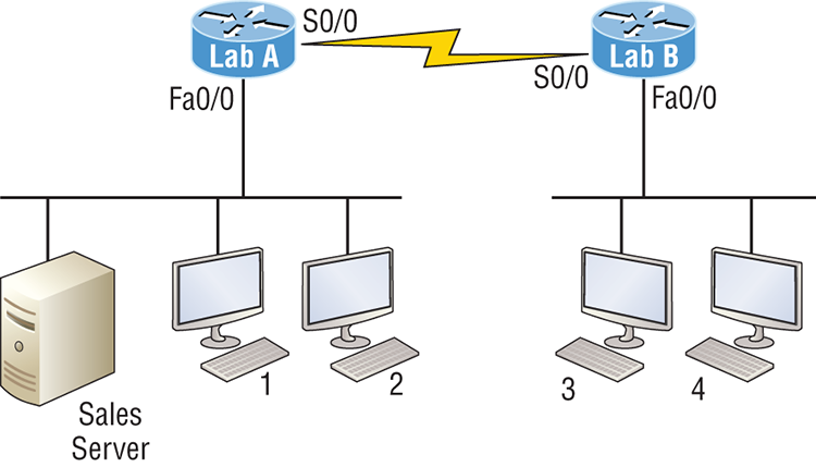
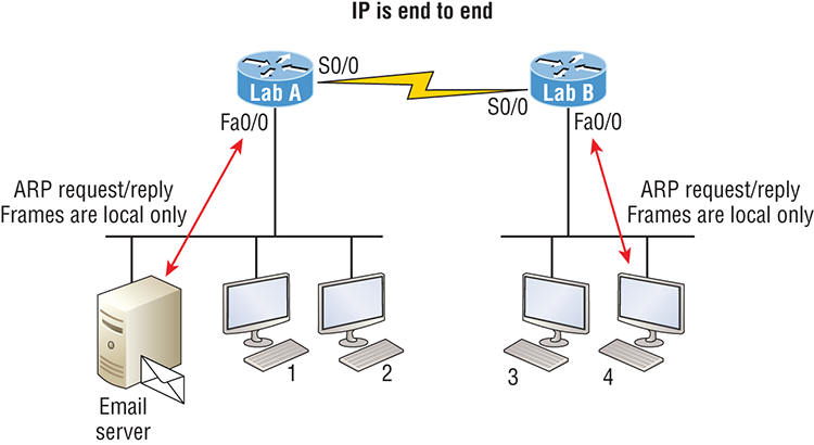
Okay—great! But we’re not quite done yet. I’ve got a few more questions for you before you actually get to configure routing in a real network. Ready? Figure 8-7 shows a basic network, and Host 4 needs to get email. Which address will be placed in the destination address field of the frame when it leaves Host 4?
Figure 8-7: Testing basic routing knowledge
The answer is that Host 4 will use the destination MAC address of the Fa0/0 interface on the Lab_B router—you knew that, right? Look at Figure 8-7 again: What if Host 4 needs to communicate with Host 1—not the server, but with Host 1. Which OSI layer 3 source address will be found in the packet header when it reaches Host 1?
Hopefully you’ve got this: At layer 3, the source IP address will be Host 4 and the destination address in the packet will be the IP address of Host 1. Of course, the destination MAC address from Host 4 will always be the Fa0/0 address of the Lab_B router, right? And since we have more than one router, we’ll need a routing protocol that communicates between both of them so that traffic can be forwarded in the right direction to reach the network that Host 1 is connected to.
Okay—one more scenario and you’re on your way to being an IP routing machine! Again, using Figure 8-7, Host 4 is transferring a file to the email server connected to the Lab_A router. What would be the layer 2 destination address leaving Host 4? Yes, I’ve asked this question more than once. But not this one: What will be the source MAC address when the frame is received at the email server?
Hopefully, you answered that the layer 2 destination address leaving Host 4 is the MAC address of the Fa0/0 interface on the Lab_B router and that the source layer 2 address that the email server will receive is the Fa0/0 interface of the Lab_A router.
If you did, you’re ready to discover how IP routing is handled in a larger network environment!
Configuring IP Routing
It’s time to get serious and configure a real network. Figure 8-8 shows three routers: Corp, SF, and LA. Remember that, by default, these routers only know about networks that are directly connected to them. I’ll continue to use this figure and network throughout the rest of the chapters in this book. As I progress through this book, I’ll add more routers and switches as needed.
As you might guess, I’ve got quite a nice collection of routers for us to play with. But you don’t need a closet full of devices to perform most, if not all, of the commands we’ll use in this book. You can get by nicely with pretty much any router or even with a good router simulator.
Getting back to business, the Corp router has two serial interfaces, which will provide a WAN connection to the SF and LA router and two Fast Ethernet interfaces as well. The two remote routers have two serial interfaces and two Fast Ethernet interfaces.
The first step for this project is to correctly configure each router with an IP address on each interface. The following list shows the IP address scheme I’m going to use to configure the network. After we go over how the network is configured, I’ll cover how to configure IP routing. Pay attention to the subnet masks—they’re important! The LANs all use a /24 mask, but the WANs are using a /30.
Figure 8-8: Configuring IP routing
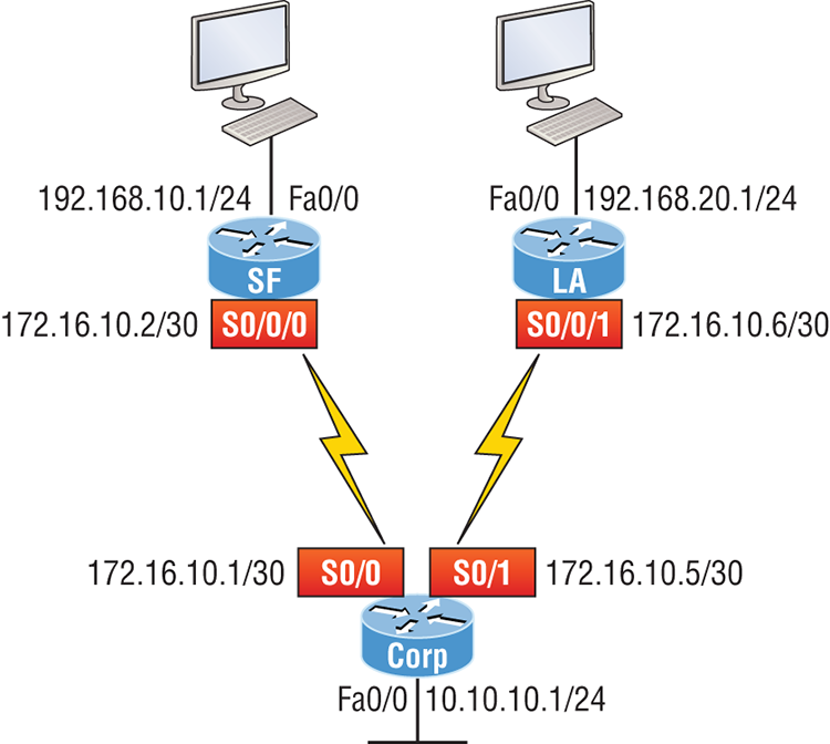
Corp
- Serial 0/0: 172.16.10.1/30
- Serial 0/1: 172.16.10.5/30
- Fa0/0: 10.10.10.1/24
SF
- S0/0/0: 172.16.10.2/30
- Fa0/0: 192.168.10.1/24
LA
- S0/0/0: 172.16.10.6/30
- Fa0/0: 192.168.20.1/24
The router configuration is really a pretty straightforward process since you just need to add IP addresses to your interfaces and then perform a no shutdown on those same interfaces. It gets a tad more complex later on, but for right now, let’s configure the IP addresses in the network.
Corp Configuration
We need to configure three interfaces to configure the Corp router. And configuring the hostnames of each router will make identification much easier. While we’re at it, let’s set the interface descriptions, banner, and router passwords too because it’s a really good idea to make a habit of configuring these commands on every router!
To get started, I performed an erase startup-config on the router and reloaded, so we’ll start in setup mode. I chose no when prompted to enter setup mode, which will get us straight to the username prompt of the console. I’m going to configure all my routers this same way.
Here’s how what I just did looks:
--- System Configuration Dialog ---
Would you like to enter the initial configuration dialog? [yes/no]: n
Press RETURN to get started!
Router>en
Router#config t
Router(config)#hostname Corp
Corp(config)#enable secret GlobalNet
Corp(config)#no ip domain-lookup
Corp(config)#int f0/0
Corp(config-if)#desc Connection to LAN BackBone
Corp(config-if)#ip address 10.10.10.1 255.255.255.0
Corp(config-if)#no shut
Corp(config-if)#int s0/0
Corp(config-if)#desc WAN connection to SF
Corp(config-if)#ip address 172.16.10.1 255.255.255.252
Corp(config-if)#no shut
Corp(config-if)#int s0/1
Corp(config-if)#desc WAN connection to LA
Corp(config-if)#ip address 172.16.10.5 255.255.255.252
Corp(config-if)#no shut
Corp(config-if)#line con 0
Corp(config-line)#password console
Corp(config-line)#login
Corp(config-line)#loggin sync
Corp(config-line)#exit
Corp(config)#line vty 0 ?
  <1-181>  Last Line number
  <cr>
Corp(config)#line vty 0 181
Corp(config-line)#password telnet
Corp(config-line)#login
Corp(config-line)#exit
Corp(config)#banner motd # This is my Corp Router #
Corp(config)#^Z
Corp#copy run start
Destination filename [startup-config]?
Building configuration...
[OK]
Corp# [OK]
Let’s talk about the configuration of the Corp router. First, I set the hostname and enable secret, but what is that no ip domain-lookup command? That command stops the router from trying to resolve hostnames, which is an annoying feature unless you’ve configured a host table or DNS. Next, I configured the three interfaces with descriptions and IP addresses and enabled them with the no shutdown command. The console and VTY passwords came next, but what is that logging sync command under the console line? The logging synchronous command stops console messages from writing over what you are typing in, meaning it’s a sanity-saving command that you’ll come to love! Last, I set my banner and then saved my configs.
To view the IP routing tables created on a Cisco router, use the command show ip route. Here’s the command’s output:
Corp#sh ip route
Codes: L - local, C - connected, S - static, R - RIP, M - mobile, B - BGP
   D - EIGRP, EX - EIGRP external, O - OSPF, IA - OSPF inter area
   N1 - OSPF NSSA external type 1, N2 - OSPF NSSA external type 2
   E1 - OSPF external type 1, E2 - OSPF external type 2
   i - IS-IS, su - IS-IS summary, L1 - IS-IS level-1, L2 - IS-IS level-2
   ia - IS-IS inter area, * - candidate default, U - per-user static route
   o - ODR, P - periodic downloaded static route, H - NHRP, l - LISP
   + - replicated route, % - next hop override
Gateway of last resort is not set
     10.0.0.0/24 is subnetted, 1 subnets
C       10.10.10.0 is directly connected, FastEthernet0/0
L       10.10.10.1/32 is directly connected, FastEthernet0/0
Corp#
It’s important to remember that only configured, directly connected networks are going to show up in the routing table. So why is it that only the FastEthernet 0/0 interface shows up in the table? No worries—that’s just because you won’t see the serial interfaces come up until the other side of the links are operational. As soon as we configure our SF and NY routers, those interfaces should pop right up!
But did you notice the C on the left side of the output of the routing table? When you see that there, it means that the network is directly connected. The codes for each type of connection are listed at the top of the show ip route command, along with their descriptions.
SF Configuration
Now we’re ready to configure the next router—SF. To make that happen correctly, keep in mind that we have two interfaces to deal with: serial 0/0/0 and FastEthernet 0/0. So let’s make sure we don’t forget to add the hostname, passwords, interface descriptions, and banners to the router configuration. As I did with the Corp router, I erased the configuration and reloaded since this router had already been configured before.
Here’s the configuration I used:
R1#erase start
% Incomplete command.
R1#erase startup-config
Erasing the nvram filesystem will remove all configuration files!
   Continue? [confirm][enter]
[OK]
Erase of nvram: complete
R1#reload
Proceed with reload? [confirm][enter]
[output cut]
%Error opening tftp://255.255.255.255/network-confg (Timed out)
%Error opening tftp://255.255.255.255/cisconet.cfg (Timed out)
--- System Configuration Dialog ---
Would you like to enter the initial configuration dialog? [yes/no]: nBefore we move on, let’s talk about this output for a second. First, notice that beginning with IOS 12.4, ISR routers will no longer take the command erase start. The router has only one command after erase that starts with s, as shown here:
Router#erase s?
startup-config
I know, you’d think that the IOS would continue to accept the command, but nope—sorry! The second thing I want to point out is that the output tells us the router is looking for a TFTP host to see if it can download a configuration. When that fails, it goes straight into setup mode. This gives you a great picture of the Cisco router default boot sequence we talked about in Chapter 7, “Managing and Troubleshooting a Cisco Internetwork.”
Okay, let’s get back to configuring our router:
Press RETURN to get started!
Router#config t
Router(config)#hostname SF
SF(config)#enable secret GlobalNet
SF(config)#no ip domain-lookup
SF(config)#int s0/0/0
SF(config-if)#desc WAN Connection to Corp
SF(config-if)#ip address 172.16.10.2 255.255.255.252
SF(config-if)#no shut
SF(config-if)#clock rate 1000000
SF(config-if)#int f0/0
SF(config-if)#desc SF LAN
SF(config-if)#ip address 192.168.10.1 255.255.255.0
SF(config-if)#no shut
SF(config-if)#line con 0
SF(config-line)#password console
SF(config-line)#login
SF(config-line)#logging sync
SF(config-line)#exit
SF(config)#line vty 0 ?
  <1-1180>  Last Line number
  <cr>
SF(config)#line vty 0 1180
SF(config-line)#password telnet
SF(config-line)#login
SF(config-line)#banner motd #This is the SF Branch router#
SF(config)#exit
SF#copy run start
Destination filename [startup-config]?
Building configuration...
 [OK]
Let’s take a look at our configuration of the interfaces with the following two commands:
SF#sh run | begin int
interface FastEthernet0/0
 description SF LAN
 ip address 192.168.10.1 255.255.255.0
 duplex auto
 speed auto
!
interface FastEthernet0/1
 no ip address
 shutdown
 duplex auto
 speed auto
!
interface Serial0/0/0
 description WAN Connection to Corp
 ip address 172.16.10.2 255.255.255.252
 clock rate 1000000
!
SF#sh ip int brief
Interface             IP-Address      OK? Method Status                Protocol
FastEthernet0/0       192.168.10.1    YES manual up                    up
FastEthernet0/1       unassigned      YES unset  administratively down down
Serial0/0/0           172.16.10.2     YES manual up                    up
Serial0/0/1           unassigned      YES unset  administratively down down
SF#
Now that both ends of the serial link are configured, the link comes up. Remember, the up/up status for the interfaces are Physical/Data Link layer status indicators that don’t reflect the layer 3 status! I ask students in my classes, “If the link shows up/up, can you ping the directly connected network?” And they say, “Yes!” The correct answer is, “I don’t know,” because we can’t see the layer 3 status with this command. We only see layers 1 and 2 and verify that the IP addresses don’t have a typo. This is really important to understand!
The show ip route command for the SF router reveals the following:
SF#sh ip route
C    192.168.10.0/24 is directly connected, FastEthernet0/0
L    192.168.10.1/32 is directly connected, FastEthernet0/0
     172.16.0.0/30 is subnetted, 1 subnets
C       172.16.10.0 is directly connected, Serial0/0/0
L       172.16.10.2/32 is directly connected, Serial0/0/0
Notice that router SF knows how to get to networks 172.16.10.0/30 and 192.168.10.0/24; we can now ping to the Corp router from SF:
SF#ping 172.16.10.1
Type escape sequence to abort.
Sending 5, 100-byte ICMP Echos to 172.16.10.1, timeout is 2 seconds:
!!!!!
Success rate is 100 percent (5/5), round-trip min/avg/max = 1/3/4 ms
Okay—now let’s head back to the Corp router and check out the routing table:
Corp>sh ip route
     172.16.0.0/30 is subnetted, 1 subnets
C       172.16.10.0 is directly connected, Serial0/0
L       172.16.10.1/32 is directly connected, Serial0/0
     10.0.0.0/24 is subnetted, 1 subnets
C       10.10.10.0 is directly connected, FastEthernet0/0
L       10.10.10.1/32 is directly connected, FastEthernet0/0
On the SF router’s serial interface 0/0/0 is a DCE connection, which means a clock rate needs to be set on the interface. Remember that you don’t need to use the clock rate command in production. While true, it’s still imperative that you know how/when you can use it and that you understand it really well when studying for your CCNA exam!
We can see our clocking with the show controllers command:
SF#sh controllers s0/0/0
Interface Serial0/0/0
Hardware is GT96K
DCE V.35, clock rate 1000000
Corp>sh controllers s0/0
Interface Serial0/0
Hardware is PowerQUICC MPC860
DTE V.35 TX and RX clocks detected.
Since the SF router has a DCE cable connection, I needed to add clock rate to this interface because DTE receives clock. Keep in mind that the new ISR routers will autodetect this and set the clock rate to 2000000. And you still need to make sure you’re able to find an interface that is DCE and set clocking to meet the objectives.
Since the serial links are showing up, we can now see both networks in the Corp routing table. And once we configure LA, we’ll see one more network in the routing table of the Corp router. The Corp router can’t see the 192.168.10.0 network because we don’t have any routing configured yet—routers see only directly connected networks by default.
LA Configuration
To configure LA, we’re going to do pretty much the same thing we did with the other two routers. There are two interfaces to deal with, serial 0/0/1 and FastEthernet 0/0, and again, we’ll be sure to add the hostname, passwords, interface descriptions, and a banner to the router configuration:
Router(config)#hostname LA
LA(config)#enable secret GlobalNet
LA(config)#no ip domain-lookup
LA(config)#int s0/0/1
LA(config-if)#ip address 172.16.10.6 255.255.255.252
LA(config-if)#no shut
LA(config-if)#clock rate 1000000
LA(config-if)#description WAN To Corporate
LA(config-if)#int f0/0
LA(config-if)#ip address 192.168.20.1 255.255.255.0
LA(config-if)#no shut
LA(config-if)#description LA LAN
LA(config-if)#line con 0
LA(config-line)#password console
LA(config-line)#login
LA(config-line)#loggin sync
LA(config-line)#exit
LA(config)#line vty 0 ?
  <1-1180>  Last Line number
  <cr>
LA(config)#line vty 0 1180
LA(config-line)#password telnet
LA(config-line)#login
LA(config-line)#exit
LA(config)#banner motd #This is my LA Router#
LA(config)#exit
LA#copy run start
Destination filename [startup-config]?
Building configuration...
[OK]
Nice—everything was pretty straightforward. The output below, which I gained via the show ip route command, displays the directly connected networks of 192.168.20.0 and 172.16.10.0:
LA#sh ip route
     172.16.0.0/30 is subnetted, 1 subnets
C       172.16.10.4 is directly connected, Serial0/0/1
L       172.16.10.6/32 is directly connected, Serial0/0/1
C    192.168.20.0/24 is directly connected, FastEthernet0/0
L    192.168.20.1/32 is directly connected, FastEthernet0/0
Okay, so now that we’ve configured all three routers with IP addresses and administrative functions, we can move on to deal with routing. But I want to do one more thing on the SF and LA routers—since this is a very small network, let’s build a DHCP server on the Corp router for each LAN.
Configuring DHCP on Our Corp Router
While it’s true that I could approach this task by going to each remote router and creating a pool, why bother with all that when I can easily create two pools on the Corp router and have the remote routers forward requests to the Corp router? Of course, you remember how to do this from Chapter 7!
Let’s give it a shot:
Corp#config t
Corp(config)#ip dhcp excluded-address 192.168.10.1
Corp(config)#ip dhcp excluded-address 192.168.20.1
Corp(config)#ip dhcp pool SF_LAN
Corp(dhcp-config)#network 192.168.10.0 255.255.255.0
Corp(dhcp-config)#default-router 192.168.10.1
Corp(dhcp-config)#dns-server 4.4.4.4
Corp(dhcp-config)#exit
Corp(config)#ip dhcp pool LA_LAN
Corp(dhcp-config)#network 192.168.20.0 255.255.255.0
Corp(dhcp-config)#default-router 192.168.20.1
Corp(dhcp-config)#dns-server 4.4.4.4
Corp(dhcp-config)#exit
Corp(config)#exit
Corp#copy run start
Destination filename [startup-config]?
Building configuration...
Creating DHCP pools on a router is actually a simple process, and you would go about the configuration the same way on any router you wish to add a DHCP pool to. To designate a router as a DHCP server, you just create the pool name, add the network/subnet and the default gateway, and then exclude any addresses that you don’t want handed out. You definitely want to make sure you’ve excluded the default gateway address, and you’d usually add a DNS server as well. I always add any exclusions first, and remember that you can conveniently exclude a range of addresses on a single line. Soon, I’ll demonstrate those verification commands I promised I’d show you back in Chapter 7, but first, we need to figure out why the Corp router still can’t get to the remote networks by default!
Now I’m pretty sure I configured DHCP correctly, but I just have this nagging feeling I forgot something important. What could that be? Well, the hosts are remote across a router, so what would I need to do that would allow them to get an address from a DHCP server? If you concluded that I’ve got to configure the SF and LA F0/0 interfaces to forward the DHCP client requests to the server, you got it!
Here’s how we’d go about doing that:
LA#config t
LA(config)#int f0/0
LA(config-if)#ip helper-address 172.16.10.5
SF#config t
SF(config)#int f0/0
SF(config-if)#ip helper-address 172.16.10.1
I’m pretty sure I did this correctly, but we won’t know until I have some type of routing configured and working. So let’s get to that next!
Configuring IP Routing in Our Network
So is our network really good to go? After all, I’ve configured it with IP addressing, administrative functions, and even clocking that will automatically occur with the ISR routers. But how will our routers send packets to remote networks when they get their destination information by looking into their tables that only include directions about directly connected networks? And you know routers promptly discard packets they receive with addresses for networks that aren’t listed in their routing table!
So we’re not exactly ready to rock after all. But we will be soon because there are several ways to configure the routing tables to include all the networks in our little internetwork so that packets will be properly forwarded. As usual, one size fits all rarely fits at all, and what’s best for one network isn’t necessarily what’s best for another. That’s why understanding the different types of routing will be really helpful when choosing the best solution for your specific environment and business requirements.
These are the three routing methods I’m going to cover with you:
- Static routing
- Default routing
- Dynamic routing
We’re going to start with the first way and implement static routing on our network, because if you can implement static routing and make it work, you’ve demonstrated that you definitely have a solid understanding of the internetwork. So let’s get started.
Static Routing
Static routing is the process that ensues when you manually add routes in each router’s routing table. Predictably, there are pros and cons to static routing, but that’s true for all routing approaches.
Here are the pros:
- There is no overhead on the router CPU, which means you could probably make do with a cheaper router than you would need for dynamic routing.
- There is no bandwidth usage between routers, saving you money on WAN links as well as minimizing overhead on the router since you’re not using a routing protocol.
- It adds security because you, the administrator, can be very exclusive and choose to allow routing access to certain networks only.
And here are the cons:
- Whoever the administrator is must have a vault-tight knowledge of the internetwork and how each router is connected in order to configure routes correctly. If you don’t have a good, accurate map of your internetwork, things will get very messy quickly!
- If you add a network to the internetwork, you have to tediously add a route to it on all routers by hand, which only gets increasingly insane as the network grows.
- Due to the last point, it’s just not feasible to use it in most large networks because maintaining it would be a full-time job in itself.
But that list of cons doesn’t mean you get to skip learning all about it mainly because of that first disadvantage I listed—the fact that you must have such a solid understanding of a network to configure it properly and that your administrative knowledge has to practically verge on the supernatural! So let’s dive in and develop those skills. Starting at the beginning, here’s the command syntax you use to add a static route to a routing table from global config:
ip route [destination_network] [mask] [next-hop_address or
  exitinterface] [administrative_distance] [permanent]
This list describes each command in the string:
Before I guide you through configuring static routes, let’s take a look at a sample static route to see what we can find out about it:
Router(config)#ip route 172.16.3.0 255.255.255.0 192.168.2.4- The ip route command tells us simply that it’s a static route.
- 172.16.3.0 is the remote network we want to send packets to.
- 255.255.255.0 is the mask of the remote network.
- 192.168.2.4 is the next hop, or router, that packets will be sent to.
But what if the static route looked like this instead?
Router(config)#ip route 172.16.3.0 255.255.255.0 192.168.2.4 150That 150 at the end changes the default administrative distance (AD) of 1 to 150. As said, I’ll talk much more about AD when we get into dynamic routing, but for now, just remember that the AD is the trustworthiness of a route, where 0 is best and 255 is worst.
One more example, then we’ll start configuring:
Router(config)#ip route 172.16.3.0 255.255.255.0 s0/0/0Instead of using a next-hop address, we can use an exit interface that will make the route show up as a directly connected network. Functionally, the next hop and exit interface work exactly the same.
To help you understand how static routes work, I’ll demonstrate the configuration on the internetwork shown previously in Figure 8-8. Here it is again in Figure 8-9 to save you the trouble of having to go back and forth to view the same figure.
Corp
Each routing table automatically includes directly connected networks. To be able to route to all indirectly connected networks within the internetwork, the routing table must include information that describes where these other networks are located and how to get to them.
The Corp router is connected to three networks. For the Corp router to be able to route to all networks, the following networks have to be configured into its routing table:
- 192.168.10.0
- 192.168.20.0
Figure 8-9: Our internetwork

The following router output shows the static routes on the Corp router and the routing table after the configuration. For the Corp router to find the remote networks, I had to place an entry into the routing table describing the remote network, the remote mask, and where to send the packets. I am going to add a 150 at the end of each line to raise the administrative distance. You’ll see why soon when we get to dynamic routing. Here’s the output:
Corp#config t
Corp(config)#ip route 192.168.10.0 255.255.255.0 172.16.10.2 150
Corp(config)#ip route 192.168.20.0 255.255.255.0 s0/1 150
Corp(config)#do show run | begin ip route
ip route 192.168.10.0 255.255.255.0 172.16.10.2 150
ip route 192.168.20.0 255.255.255.0 Serial0/1 150
I needed to use different paths for networks 192.168.10.0 and 192.168.20.0, so I used a next-hop address for the SF router and an exit interface for the LA router. After the router has been configured, you can just typeshow ip route to see the static routes:
Corp(config)#do show ip route
S    192.168.10.0/24 [150/0] via 172.16.10.2
     172.16.0.0/30 is subnetted, 2 subnets
C       172.16.10.4 is directly connected, Serial0/1
L       172.16.10.5/32 is directly connected, Serial0/1
C       172.16.10.0 is directly connected, Serial0/0
L       172.16.10.1/32 is directly connected, Serial0/0
S    192.168.20.0/24 is directly connected, Serial0/1
     10.0.0.0/24 is subnetted, 1 subnets
C       10.10.10.0 is directly connected, FastEthernet0/0
L       10.10.10.1/32 is directly connected, FastEthernet0/0
The Corp router is configured to route and know all routes to all networks. But can you see a difference in the routing table for the routes to SF and LA? That’s right! The next-hop configuration showed up as via, and the route configured with an exit interface configuration shows up as static but also as directly connected! This demonstrates how they are functionally the same but will display differently in the routing table.
Understand that if the routes don’t appear in the routing table, it’s because the router can’t communicate with the next-hop address you’ve configured. But you can still use the permanent parameter to keep the route in the routing table even if the next-hop device can’t be contacted.
The S in the first routing table entry means that the route is a static entry. The [150/0] stands for the administrative distance and metric to the remote network, respectively.
Okay—we’re good. The Corp router now has all the information it needs to communicate with the other remote networks. Still, keep in mind that if the SF and LA routers aren’t configured with all the same information, the packets will be discarded. We can fix this by configuring static routes.
SF
The SF router is directly connected to networks 172.16.10.0/30 and 192.168.10.0/24, which means I’ve got to configure the following static routes on the SF router:
- 10.10.10.0/24
- 192.168.20.0/24
- 172.16.10.4/30
The configuration for the SF router is revealed in the output below. Remember that we’ll never create a static route to any network we’re directly connected to as well as the fact that we must use the next hop of 172.16.10.1 since that’s our only router connection. Let’s check out the commands:
SF(config)#ip route 10.10.10.0 255.255.255.0 172.16.10.1 150
SF(config)#ip route 172.16.10.4 255.255.255.252 172.16.10.1 150
SF(config)#ip route 192.168.20.0 255.255.255.0 172.16.10.1 150
SF(config)#do show run | begin ip route
ip route 10.10.10.0 255.255.255.0 172.16.10.1 150
ip route 172.16.10.4 255.255.255.252 172.16.10.1 150
ip route 192.168.20.0 255.255.255.0 172.16.10.1 150
By looking at the routing table, you can see that the SF router now understands how to find each network:
SF(config)#do show ip route
C    192.168.10.0/24 is directly connected, FastEthernet0/0
L    192.168.10.1/32 is directly connected, FastEthernet0/0
     172.16.0.0/30 is subnetted, 3 subnets
S       172.16.10.4 [150/0] via 172.16.10.1
C       172.16.10.0 is directly connected, Serial0/0/0
L       172.16.10.2/32 is directly connected, Serial0/0
S    192.168.20.0/24 [150/0] via 172.16.10.1
     10.0.0.0/24 is subnetted, 1 subnets
S       10.10.10.0 [150/0] via 172.16.10.1
And we now can rest assured that the SF router has a complete routing table as well. As soon as the LA router has all the networks in its routing table, SF will be able to communicate with all remote networks!
LA
The LA router is directly connected to 192.168.20.0/24 and 172.16.10.4/30, so these are the routes that must be added:
- 10.10.10.0/24
- 172.16.10.0/30
- 192.168.10.0/24
And here’s the LA router’s configuration:
LA#config t
LA(config)#ip route 10.10.10.0 255.255.255.0 172.16.10.5 150
LA(config)#ip route 172.16.10.0 255.255.255.252 172.16.10.5 150
LA(config)#ip route 192.168.10.0 255.255.255.0 172.16.10.5 150
LA(config)#do show run | begin ip route
ip route 10.10.10.0 255.255.255.0 172.16.10.5 150
ip route 172.16.10.0 255.255.255.252 172.16.10.5 150
ip route 192.168.10.0 255.255.255.0 172.16.10.5 150
This output displays the routing table on the LA router:
LA(config)#do sho ip route
S    192.168.10.0/24 [150/0] via 172.16.10.5
     172.16.0.0/30 is subnetted, 3 subnets
C       172.16.10.4 is directly connected, Serial0/0/1
L       172.16.10.6/32 is directly connected, Serial0/0/1
S       172.16.10.0 [150/0] via 172.16.10.5
C    192.168.20.0/24 is directly connected, FastEthernet0/0
L    192.168.20.1/32 is directly connected, FastEthernet0/0
     10.0.0.0/24 is subnetted, 1 subnets
S       10.10.10.0 [150/0] via 172.16.10.5
LA now shows all five networks in the internetwork, so it too can now communicate with all routers and networks. But before we test our little network, as well as our DHCP server, let’s cover one more topic.
Default Routing
The SF and LA routers that I’ve connected to the Corp router are considered stub routers. A stub indicates that the networks in this design have only one way out to reach all other networks, which means that instead of creating multiple static routes, we can just use a single default route. This default route is used by IP to forward any packet with a destination not found in the routing table, which is why it is also called a gateway of last resort. Here’s the configuration I could have done on the LA router instead of typing in the static routes due to its stub status:
LA#config t
LA(config)#no ip route 10.10.10.0 255.255.255.0 172.16.10.5 150
LA(config)#no ip route 172.16.10.0 255.255.255.252 172.16.10.5 150
LA(config)#no ip route 192.168.10.0 255.255.255.0 172.16.10.5 150
LA(config)#ip route 0.0.0.0 0.0.0.0 172.16.10.5
LA(config)#do sho ip route
[output cut]
Gateway of last resort is 172.16.10.5 to network 0.0.0.0
172.16.0.0/30 is subnetted, 1 subnets
C       172.16.10.4 is directly connected, Serial0/0/1
L       172.16.10.6/32 is directly connected, Serial0/0/1
C    192.168.20.0/24 is directly connected, FastEthernet0/0
L    192.168.20.0/32 is directly connected, FastEthernet0/0
S*   0.0.0.0/0 [1/0] via 172.16.10.5
Okay—I’ve removed all the initial static routes I had configured and adding a default route is a lot easier than typing a bunch of static routes! Can you see the default route listed last in the routing table? The S* shows that as a candidate for the default route. And I really want you to notice that the gateway of last resort is now set too. Everything the router receives with a destination not found in the routing table will be forwarded to 172.16.10.5. You need to be careful where you place default routes because you can easily create a network loop!
So we’re there—we’ve configured all our routing tables! All the routers have the correct routing table, so all routers and hosts should be able to communicate without a hitch—for now. But if you add even one more network or another router to the internetwork, you’ll have to update each and every router’s routing tables by hand—ugh! Not really a problem at all if you’ve got a small network like we do, but it would be a time-consuming monster if you’re dealing with a large internetwork!
Verifying Your Configuration
We’re still not done yet—once all the routers’ routing tables are configured, they must be verified. The best way to do this, besides using the show ip route command, is via Ping. I’ll start by pinging from the Corp router to the SF router.
Here’s the output I got:
Corp#ping 192.168.10.1Type escape sequence to abort.
Sending 5, 100-byte ICMP Echos to 192.168.10.1, timeout is 2 seconds:
!!!!!
Success rate is 100 percent (5/5), round-trip min/avg/max = 4/4/4 ms
Corp#Here you can see that I pinged from the Corp router to the remote interface of the SF router. Now let’s ping the remote network on the LA router, and after that, we’ll test our DHCP server and see if that is working too!
Corp#ping 192.168.20.1
Type escape sequence to abort.
Sending 5, 100-byte ICMP Echos to 192.168.20.1, timeout is 2 seconds:
!!!!!
Success rate is 100 percent (5/5), round-trip min/avg/max = 1/2/4 ms
Corp#
And why not test my configuration of the DHCP server on the Corp router while we’re at it? I’m going to go to each host on the SF and LA routers and make them DHCP clients. By the way, I’m using an old router to represent “hosts,” which just happens to work great for studying purposes. Here’s how I did that:
SF_PC(config)#int e0
SF_PC(config-if)#ip address dhcp
SF_PC(config-if)#no shut
Interface Ethernet0 assigned DHCP address 192.168.10.8, mask 255.255.255.0
LA_PC(config)#int e0
LA_PC(config-if)#ip addr dhcp
LA_PC(config-if)#no shut
Interface Ethernet0 assigned DHCP address 192.168.20.4, mask 255.255.255.0
Nice! Don’t you love it when things just work the first time? Sadly, this just isn’t exactly a realistic expectation in the networking world, so we must be able to troubleshoot and verify our networks. Let’s verify our DHCP server with a few of the commands you learned back in Chapter 7:
Corp#sh ip dhcp binding
Bindings from all pools not associated with VRF:
IP address          Client-ID/              Lease expiration        Type
                    Hardware address/
                    User name
192.168.10.8        0063.6973.636f.2d30.    Sept 16 2013 10:34 AM    Automatic
                    3035.302e.3062.6330.
                    2e30.3063.632d.4574.
                    30
192.168.20.4        0063.6973.636f.2d30.    Sept 16 2013 10:46 AM    Automatic
                    3030.322e.3137.3632.
                    2e64.3032.372d.4574.
                    30
We can see from above that our little DHCP server is working! Let’s try another couple of commands:
Corp#sh ip dhcp pool SF_LANPool SF_LAN :
Utilization mark (high/low) : 100 / 0
Subnet size (first/next) : 0 / 0
Total addresses : 254
Leased addresses : 3
Pending event : none
1 subnet is currently in the pool :
Current index IP address range Leased addresses
192.168.10.9 192.168.10.1 - 192.168.10.254 3
Corp#sh ip dhcp conflict
IP address        Detection method   Detection time          VRF
The last command would tell us if we had two hosts with the same IP address, so it’s good news because there are no conflicts reported! Two detection methods are used to confirm this:
- Ping from the DHCP server to make sure no other host responds before handing out an address.
- A gratuitous ARP from a host that receives a DHCP address from the server.
The DHCP client will send an ARP request with its new IP address looking to see if anyone responds, and if so, it will report the conflict to the server.
Okay, since we can communicate from end to end and to each host without a problem while receiving DHCP addresses from our server, I’d say our static and default route configurations have been a success—cheers!
Dynamic Routing
Dynamic routing is when protocols are used to find networks and update routing tables on routers. This is whole lot easier than using static or default routing, but it will cost you in terms of router CPU processing and bandwidth on network links. A routing protocol defines the set of rules used by a router when it communicates routing information between neighboring routers.
The routing protocol I’m going to talk about in this chapter is Routing Information Protocol (RIP) versions 1 and 2.
Two types of routing protocols are used in internetworks: interior gateway protocols (IGPs) and exterior gateway protocols (EGPs). IGPs are used to exchange routing information with routers in the same autonomous system (AS). An AS is either a single network or a collection of networks under a common administrative domain, which basically means that all routers sharing the same routing-table information are in the same AS. EGPs are used to communicate between ASs. An example of an EGP is Border Gateway Protocol (BGP), which we’re not going to bother with because it’s beyond the scope of this book.
Since routing protocols are so essential to dynamic routing, I’m going to give you the basic information you need to know about them next. Later on in this chapter, we’ll focus on configuration.
Routing Protocol Basics
There are some important things you should know about routing protocols before we get deeper into them. Being familiar with administrative distances, the three different kinds of routing protocols, and routing loops are three of the most important.
Administrative Distances
The administrative distance (AD) is used to rate the trustworthiness of routing information received on a router from a neighbor router. An administrative distance is an integer from 0 to 255, where 0 is the most trusted and 255 means no traffic will be passed via this route.
If a router receives two updates listing the same remote network, the first thing the router checks is the AD. If one of the advertised routes has a lower AD than the other, then the route with the lowest AD will be chosen and placed in the routing table.
If both advertised routes to the same network have the same AD, then routing protocol metrics like hop count and/or the bandwidth of the lines will be used to find the best path to the remote network. The advertised route with the lowest metric will be placed in the routing table, but if both advertised routes have the same AD as well as the same metrics, then the routing protocol will load-balance to the remote network, meaning the protocol will send data down each link.
Table 8-1 shows the default administrative distances that a Cisco router uses to decide which route to take to a remote network.
Table 8-1: Default administrative distances
| Route Source | Default AD |
| Connected interface | 0 |
| Static route | 1 |
| EIGRP | 90 |
| OSPF | 110 |
| RIP | 120 |
| External EIGRP | 170 |
| Unknown | 255 (This route will never be used.) |
If a network is directly connected, the router will always use the interface connected to the network. If you configure a static route, the router will then believe that route over any other ones it learns about. You can change the administrative distance of static routes, but by default, they have an AD of 1. In our previous static route configuration, the AD of each route is set at 150. This AD allows us to configure routing protocols without having to remove the static routes because it’s nice to have them there for backup in case the routing protocol experiences some kind of failure.
If you have a static route, an RIP-advertised route, and an EIGRP-advertised route listing the same network, which route will the router go with? That’s right—by default, the router will always use the static route unless you change its AD—which we did!
Routing Protocols
There are three classes of routing protocols:
There’s no set of rules to follow that dictate exactly how to broadly configure routing protocols for every situation. It’s a task that really must be undertaken on a case-by-case basis, with an eye on specific requirements of each one. If you understand how the different routing protocols work, you can make good, solid decisions that will solidly meet the individual needs of any business!
Routing Information Protocol (RIP)
Routing Information Protocol (RIP) is a true distance-vector routing protocol. RIP sends the complete routing table out of all active interfaces every 30 seconds. It relies on hop count to determine the best way to a remote network, but it has a maximum allowable hop count of 15 by default, so a destination of 16 would be considered unreachable. RIP works okay in very small networks, but it’s super inefficient on large networks with slow WAN links or on networks with a large number of routers installed and completely useless on networks that have links with variable bandwidths!
RIP version 1 uses only classful routing, which means that all devices in the network must use the same subnet mask. This is because RIP version 1 doesn’t send updates with subnet mask information in tow. RIP version 2 provides something called prefix routing and does send subnet mask information with its route updates. This is called classless routing. You’ll rarely see RIPv1 used in today’s networks, and it’s not considered in any CCENT and CCNA objective. Even RIPv2 doesn’t get much attention in the objectives. So why am I even telling you about them? Because it helps me explain routing protocols a little better before we get into the much more advanced, and very much focused upon, OSPF protocol.
So, with that let’s configure our current network with RIPv2, before we move onto OSPF in the next chapter.
Configuring RIP Routing
To configure RIP routing, just turn on the protocol with the router rip command and tell the RIP routing protocol the networks to advertise. Remember that with static routing, we always configured remote networks and never typed a route to our directly connected networks? Well, dynamic routing is carried out the complete opposite way. You would never type a remote network under your routing protocol—only enter your directly connected networks! Let’s configure our three-router internetwork, revisited in Figure 8-9, with RIP routing.
Corp
RIP has an administrative distance of 120. Static routes have an administrative distance of 1 by default, and since we currently have static routes configured, the routing tables won’t be populated with RIP information. We’re still good though because I added the 150 to the end of each static route!
You can add the RIP routing protocol by using the router rip command and the network command. The network command tells the routing protocol which classful network to advertise. By doing this, you’re activating the RIP routing process on the interfaces whose addressing falls within the specified classful networks configured with the network command under the RIP routing process.
Look at the Corp router configuration to see how easy this is. Oh wait—first, I want to verify my directly connected networks so I know what to configure RIP with:
Corp#sh ip int brief
Interface        IP-Address      OK? Method Status                Protocol
FastEthernet0/0  10.10.10.1      YES manual up                    up
Serial0/0        172.16.10.1     YES manual up                    up
FastEthernet0/1  unassigned      YES unset  administratively down down
Serial0/1        172.16.10.5     YES manual up                    up
Corp#config t
Corp(config)#router rip
Corp(config-router)#network 10.0.0.0
Corp(config-router)#network 172.16.0.0
Corp(config-router)#version 2
Corp(config-router)#no auto-summary
That’s it—really! Typically just two or three commands and you’re done, which sure makes your job a lot easier than dealing with static routes, doesn’t it? Be sure to keep in mind the extra router CPU process and bandwidth that you’re consuming.
Anyway, so what exactly did I do here? I enabled the RIP routing protocol, added my directly connected networks, made sure I was only running RIPv2, which is a classless routing protocol, and then I disabled auto-summary. We typically don’t want our routing protocols summarizing for us because it’s better to do that manually and both RIP and EIGRP auto-summarize by default. So a general rule of thumb is to disable auto-summary, which allows them to advertise subnets.
Notice I didn’t type in subnets, only the classful network address, which is betrayed by the fact that all subnet bits and host bits are off! That’s because with dynamic routing, it’s not my job and it’s up to the routing protocol to find the subnets and populate the routing tables. And since we have no router buddies running RIP, we won’t see any RIP routes in the routing table yet.
SF
Okay, let’s configure our SF router now, which is connected to two networks. We need to configure both directly connected classful networks, not subnets:
SF#sh ip int brief
Interface         IP-Address      OK? Method Status             Protocol
FastEthernet0/0   192.168.10.1    YES manual up                    up
FastEthernet0/1   unassigned      YES unset  administratively down down
Serial0/0/0       172.16.10.2     YES manual up                    up
Serial0/0/1       unassigned      YES unset  administratively down down
SF#config
SF(config)#router rip
SF(config-router)#network 192.168.10.0
SF(config-router)#network 172.16.0.0
SF(config-router)#version 2
SF(config-router)#no auto-summary
SF(config-router)#do show ip route
C    192.168.10.0/24 is directly connected, FastEthernet0/0
L    192.168.10.1/32 is directly connected, FastEthernet0/0
     172.16.0.0/30 is subnetted, 3 subnets
R       172.16.10.4 [120/1] via 172.16.10.1, 00:00:08, Serial0/0/0
C       172.16.10.0 is directly connected, Serial0/0/0
L       172.16.10.2/32 is directly connected, Serial0/0
S    192.168.20.0/24 [150/0] via 172.16.10.1
     10.0.0.0/24 is subnetted, 1 subnets
R       10.10.10.0 [120/1] via 172.16.10.1, 00:00:08, Serial0/0/0
That was pretty straightforward. Let’s talk about this routing table. Since we have one RIP buddy out there whom we are exchanging routing tables with, we can see the RIP networks coming from the Corp router. All the other routes still show up as static and local. RIP also found both connections through the Corp router to networks 10.10.10.0 and 172.16.10.4. But we’re not done yet!
LA
Let’s configure our LA router with RIP, only I’m going to remove the default route first, even though I don’t have to. You’ll see why soon:
LA#config t
LA(config)#no ip route 0.0.0.0 0.0.0.0
LA(config)#router rip
LA(config-router)#network 192.168.20.0
LA(config-router)#network 172.16.0.0
LA(config-router)#no auto
LA(config-router)#vers 2
LA(config-router)#do show ip route
R    192.168.10.0/24 [120/2] via 172.16.10.5, 00:00:10, Serial0/0/1
     172.16.0.0/30 is subnetted, 3 subnets
C       172.16.10.4 is directly connected, Serial0/0/1
L       172.16.10.6/32 is directly connected, Serial0/0/1
R       172.16.10.0 [120/1] via 172.16.10.5, 00:00:10, Serial0/0/1
C    192.168.20.0/24 is directly connected, FastEthernet0/0
L    192.168.20.1/32 is directly connected, FastEthernet0/0
     10.0.0.0/24 is subnetted, 1 subnets
R       10.10.10.0 [120/1] via 172.16.10.5, 00:00:10, Serial0/0/1
The routing table is sprouting new Rs as we add RIP buddies! We can still see that all routes are in the routing table.
This output shows us basically the same routing table and the same entries that it had when we were using static routes—except for those Rs. An R indicates that the networks were added dynamically using the RIP routing protocol. The [120/1] is the administrative distance of the route (120) along with the metric, which for RIP is the number of hops to that remote network (1). From the Corp router, all networks are one hop away.
So, while yes, it’s true that RIP has worked in our little internetwork, it’s just not a great solution for most enterprises. Its maximum hop count of only 15 is a highly limiting factor. And it performs full routing-table updates every 30 seconds, which would bring a larger internetwork to a painful crawl in no time!
There’s still one more thing I want to show you about RIP routing tables and the parameters used to advertise remote networks. Using a different router on a different network as an example for a second, look into the output below. Can you spot where the following routing table shows [120/15] in the 10.1.3.0 network metric? This means that the administrative distance is 120, the default for RIP, but the hop count is 15. Remember that each time a router sends out an update to a neighbor router, the hop count goes up by one incrementally for each route! Here’s that output now:
Router#sh ip route
     10.0.0.0/24 is subnetted, 12 subnets
C       10.1.11.0 is directly connected, FastEthernet0/1
L       10.1.11.1/32 is directly connected, FastEthernet0/1
C       10.1.10.0 is directly connected, FastEthernet0/0
L       10.1.10.1/32 is directly connected, FastEthernet/0/0
R       10.1.9.0 [120/2] via 10.1.5.1, 00:00:15, Serial0/0/1
R       10.1.8.0 [120/2] via 10.1.5.1, 00:00:15, Serial0/0/1
R       10.1.12.0 [120/1] via 10.1.11.2, 00:00:00, FastEthernet0/1
R       10.1.3.0 [120/15] via 10.1.5.1, 00:00:15, Serial0/0/1
R       10.1.2.0 [120/1] via 10.1.5.1, 00:00:15, Serial0/0/1
R       10.1.1.0 [120/1] via 10.1.5.1, 00:00:15, Serial0/0/1
R       10.1.7.0 [120/2] via 10.1.5.1, 00:00:15, Serial0/0/1
R       10.1.6.0 [120/2] via 10.1.5.1, 00:00:15, Serial0/0/1
C       10.1.5.0 is directly connected, Serial0/0/1
L       10.1.5.1/32 is directly connected, Serial0/0/1
R       10.1.4.0 [120/1] via 10.1.5.1, 00:00:15, Serial0/0/1
So this [120/15] is really bad. We’re basically doomed because the next router that receives the table from this router will just discard the route to network 10.1.3.0 since the hop count would rise to 16, which is invalid!
Holding Down RIP Propagations
You probably don’t want your RIP network advertised everywhere on your LAN and WAN. There’s enough stress in networking already and not a whole lot to be gained by advertising your RIP network to the Internet!
There are a few different ways to stop unwanted RIP updates from propagating across your LANs and WANs, and the easiest one is through the passive-interface command. This command prevents RIP update broadcasts from being sent out of a specified interface but still allows that same interface to receive RIP updates.
Here’s an example of how to configure a passive-interface on the Corp routers Fa0/1 interface, which we will pretend is connected to a LAN that we don’t want RIP on:
Corp#config t
Corp(config)#router rip
Corp(config-router)#passive-interface FastEthernet 0/1
This command will stop RIP updates from being propagated out of FastEthernet interface 0/0, but this can still receive RIP updates.
Advertising a Default Route Using RIP
Okay, now I’m going to guide you through how to advertise a way out of your autonomous system to other routers, and you’ll see this is completed the same way with OSPF. Imagine that our Corp router’s Fa0/0 interface is connected to some type of Metro-Ethernet as a connection to the Internet. This is a pretty common configuration today that uses a LAN interface to connect to the ISP instead of a serial interface.
If we do add an Internet connection to Corp, all routers in our AS (SF and LA) must know where to send packets destined for networks on the Internet or they’ll just drop the packets when they get a remote request. One solution to this little hitch would be to place a default route on every router and funnel the information to Corp, which in turn would have a default route to the ISP. Most people do this type of configuration in small- to medium-size networks because it actually works pretty well!
But since I’m running RIPv2 on all routers, I’ll just add a default route on the Corp router to our ISP, as I would normally. I’ll then add another command to advertise my network to the other routers in the AS as the default route to show them where to send packets destined for the Internet.
Here’s my new Corp configuration:
Corp(config)#ip route 0.0.0.0 0.0.0.0 fa0/0
Corp(config)#router rip
Corp(config-router)#default-information originate
Now, let’s take a look at the last entry found in the Corp routing table:
S* 0.0.0.0/0 is directly connected, FastEthernet0/0Let’s see if the LA router can see this same entry:
LA#sh ip route
Gateway of last resort is 172.16.10.5 to network 0.0.0.0
R    192.168.10.0/24 [120/2] via 172.16.10.5, 00:00:04, Serial0/0/1
     172.16.0.0/30 is subnetted, 2 subnets
C       172.16.10.4 is directly connected, Serial0/0/1
L       172.16.10.5/32 is directly connected, Serial0/0/1
R       172.16.10.0 [120/1] via 172.16.10.5, 00:00:04, Serial0/0/1
C    192.168.20.0/24 is directly connected, FastEthernet0/0
L    192.168.20.1/32 is directly connected, FastEthernet0/0
     10.0.0.0/24 is subnetted, 1 subnets
R       10.10.10.0 [120/1] via 172.16.10.5, 00:00:04, Serial0/0/1
R    192.168.218.0/24 [120/3] via 172.16.10.5, 00:00:04, Serial0/0/1
R    192.168.118.0/24 [120/2] via 172.16.10.5, 00:00:05, Serial0/0/1
R*   0.0.0.0/0 [120/1] via 172.16.10.5, 00:00:05, Serial0/0/1R2#
Can you see that last entry? It screams that it’s an RIP injected route, but it’s also a default route so our default-information originate command is working! Last, notice that the gateway of last resort is now set as well.
If all of what you’ve learned is clear and understood, congratulations—you’re ready to move on to the next chapter right after you go through the written and hands-on labs, and while you’re at it, don’t forget the review questions!
Summary
This chapter covered IP routing in detail. Again, it’s extremely important to fully understand the basics we covered in this chapter because everything that’s done on a Cisco router will typically have some kind of IP routing configured and running.
You learned how IP routing uses frames to transport packets between routers and to the destination host. From there, we configured static routing on our routers and discussed the administrative distance used by IP to determine the best route to a destination network. You found out that if you have a stub network, you can configure default routing, which sets the gateway of last resort on a router.
We then discussed dynamic routing, specifically RIP and how it works on an internetwork, which is not very well!
Exam Essentials
Written Lab 8
The answers to this lab can be found in Appendix A, “Answers to Written Labs.”
Write the answers to the following questions:
Hands-on Labs
In the following hands-on labs, you will configure a network with three routers. These exercises assume all the same setup requirements as the labs found in earlier chapters.
This chapter includes the following labs:
The internetwork shown in the following graphic will be used to configure all routers.
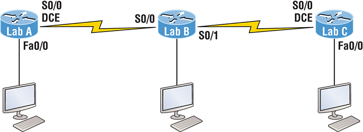
Table 8-2 shows our IP addresses for each router (each interface uses a /24 mask).
Table 8-2: Our IP addresses
| Router | Interface | IP Address |
| Lab_A | Fa0/0 | 172.16.10.1 |
| Lab_A | S0/0 | 172.16.20.1 |
| Lab_B | S0/0 | 172.16.20.2 |
| Lab_B | S0/1 | 172.16.30.1 |
| Lab_C | S0/0 | 172.16.30.2 |
| Lab_C | Fa0/0 | 172.16.40.1 |
These labs were written without using the LAN interface on the Lab_B router. You can choose to add that LAN into the labs if necessary. Also, if you have enough LAN interfaces, then you don’t need to add the serial interfaces into this lab. Using all LAN interfaces is fine.
Hands-on Lab 8.1: Creating Static Routes
In this lab, you will create a static route in all three routers so that the routers see all networks. Verify with the Ping program when complete.
Lab_A#config t
Lab_A(config)#ip route 172.16.30.0 255.255.255.0
  172.16.20.2
Lab_A(config)#ip route 172.16.40.0 255.255.255.0
172.16.20.2Lab_B#config t
Lab_B(config)#ip route 172.16.10.0 255.255.255.0
172.16.20.1
Lab_B(config)#ip route 172.16.40.0 255.255.255.0
172.16.30.2Lab_C#config t
Lab_C(config)#ip route 172.16.10.0 255.255.255.0
172.16.30.1
Lab_C(config)#ip route 172.16.20.0 255.255.255.0
172.16.30.1Hands-on Lab 8.2: Configuring RIP Routing
In this lab, we will use the dynamic routing protocol RIP instead of static routing.
Lab_A#config t
Lab_A(config)#no ip route 172.16.30.0 255.255.255.0
  172.16.20.2
Lab_A(config)#no ip route 172.16.40.0 255.255.255.0
172.16.20.2config t
router ripConfig t
Router rip
network 172.16.0.0show ip protocolsshow ip routeshow running-config or show runReview Questions
The answers to these questions can be found in Appendix B, “Answers to Chapter Review Questions.”
1. What command was used to generate the following output?
Codes: L - local, C - connected, S - static,
[output cut]
        10.0.0.0/8 is variably subnetted, 6 subnets, 4 masks
C       10.0.0.0/8 is directly connected, FastEthernet0/3
L       10.0.0.1/32 is directly connected, FastEthernet0/3
C       10.10.0.0/16 is directly connected, FastEthernet0/2
L       10.10.0.1/32 is directly connected, FastEthernet0/2
C       10.10.10.0/24 is directly connected, FastEthernet0/1
L       10.10.10.1/32 is directly connected, FastEthernet0/1
S*      0.0.0.0/0 is directly connected, FastEthernet0/0
2. You are viewing the routing table and you see an entry 10.1.1.1/32. What legend code would you expect to see next to this route?
A. C
B. L
C. S
D. D
3. Which of the following statements are true regarding the command ip route 172.16.4.0 255.255.255.0 192.168.4.2? (Choose two.)
A. The command is used to establish a static route.
B. The default administrative distance is used.
C. The command is used to configure the default route.
D. The subnet mask for the source address is 255.255.255.0.
E. The command is used to establish a stub network.
4. What destination addresses will be used by HostA to send data to the HTTPS server as shown in the following network? (Choose two.)
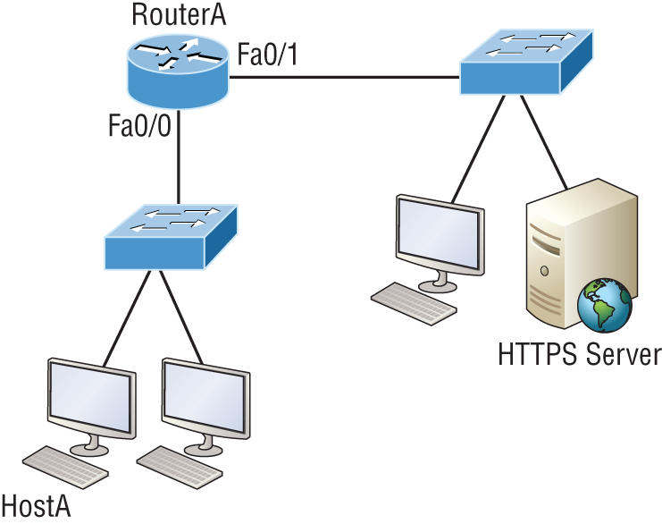
A. The IP address of the switch
B. The MAC address of the remote switch
C. The IP address of the HTTPS server
D. The MAC address of the HTTPS server
E. The IP address of RouterA’s Fa0/0 interface
F. The MAC address of RouterA’s Fa0/0 interface
5. Using the output shown, what protocol was used to learn the MAC address for 172.16.10.1?
Interface: 172.16.10.2 --- 0x3
  Internet Address      Physical Address      Type
  172.16.10.1          00-15-05-06-31-b0     dynamic
A. ICMP
B. ARP
C. TCP
D. UDP
6. Which of the following is called an advanced distance-vector routing protocol?
A. OSPF
B. EIGRP
C. BGP
D. RIP
7. When a packet is routed across a network, the ______________ in the packet changes at every hop while the ____ does not.
A. MAC address, IP address
B. IP address, MAC address
C. Port number, IP address
D. IP address, port number
8. Which statement is true regarding classless routing protocols? (Choose two.)
A. The use of discontiguous networks is not allowed.
B. The use of variable length subnet masks is permitted.
C. RIPv1 is a classless routing protocol.
D. IGRP supports classless routing within the same autonomous system.
E. RIPv2 supports classless routing.
9. Which two of the following are true regarding the distance-vector and link-state routing protocols? (Choose two.)
A. Link state sends its complete routing table out of all active interfaces at periodic time intervals.
B. Distance vector sends its complete routing table out of all active interfaces at periodic time intervals.
C. Link state sends updates containing the state of its own links to all routers in the internetwork.
D. Distance vector sends updates containing the state of its own links to all routers in the internetwork.
10. When a router looks up the destination in the routing table for every single packet it is called _____________ .
A. dynamic switching
B. fast switching
C. process switching
D. Cisco Express Forwarding
11. What type(s) of route is the following? Choose all that apply.
S* 0.0.0.0/0 [1/0] via 172.16.10.5
A. Default
B. Subnetted
C. Static
D. Local
12. A network administrator views the output from the show ip route command. A network that is advertised by both RIP and EIGRP appears in the routing table flagged as an EIGRP route. Why is the RIP route to this network not used in the routing table?
A. EIGRP has a faster update timer.
B. EIGRP has a lower administrative distance.
C. RIP has a higher metric value for that route.
D. The EIGRP route has fewer hops.
E. The RIP path has a routing loop.
13. Which of the following is NOT an advantage of static routing?
A. Less overhead on the router CPU
B. No bandwidth usage between routers
C. Adds security
D. Recovers automatically from lost routes
14. What metric does RIPv2 use to find the best path to a remote network?
A. Hop count
B. MTU
C. Cumulative interface delay
D. Load
E. Path bandwidth value
15. The Corporate router receives an IP packet with a source IP address of 192.168.214.20 and a destination address of 192.168.22.3. Looking at the output from the Corp router, what will the router do with this packet?
Corp#sh ip route
[output cut]
R    192.168.215.0 [120/2] via 192.168.20.2, 00:00:23, Serial0/0
R    192.168.115.0 [120/1] via 192.168.20.2, 00:00:23, Serial0/0
R    192.168.30.0 [120/1] via 192.168.20.2, 00:00:23, Serial0/0
C    192.168.20.0 is directly connected, Serial0/0
C    192.168.214.0 is directly connected, FastEthernet0/0
A. The packet will be discarded.
B. The packet will be routed out of the S0/0 interface.
C. The router will broadcast looking for the destination.
D. The packet will be routed out of the Fa0/0 interface.
16. If your routing table has a static, an RIP, and an EIGRP route to the same network, which route will be used to route packets by default?
A. Any available route
B. RIP route
C. Static route
D. EIGRP route
E. They will all load-balance.
17. Which of the following is an EGP?
A. RIPv2
B. EIGRP
C. BGP
D. RIP
18. Which of the following is an advantage of static routing?
A. Less overhead on the router CPU
B. No bandwidth usage between routers
C. Adds security
D. Recovers automatically from lost routes
19. What command produced the following output?
Interface         IP-Address      OK? Method Status             Protocol
FastEthernet0/0   192.168.10.1    YES manual up                    up
FastEthernet0/1   unassigned      YES unset  administratively down down
Serial0/0/0       172.16.10.2     YES manual up                    up
Serial0/0/1       unassigned      YES unset  administratively down down
A. show ip route
B. show interfaces
C. show ip interface brief
D. show ip arp
20. In the following command what does the 150 at the end of the command mean?
Router(config)#ip route 172.16.3.0 255.255.255.0 192.168.2.4 150
A. Metric
B. Administrative distance
C. Hop count
D. Cost