Chapter 9
Open Shortest Path First (OSPF)
The following ICND1 exam topics are covered in this chapter:
- IP Routing Technologies
- Configure and verify OSPF (single area)
- Benefit of single area
- Configure OSPF v2
- Router ID
- Passive interface
Open Shortest Path First (OSPF) is by far the most popular and important routing protocol in use today—so important, I’m devoting this entire chapter to it! Sticking with the same approach we’ve adhered to throughout this book, we’ll begin with the basics by completely familiarizing you with key OSPF terminology. Once we’ve covered that thoroughly, I’ll guide you through OSPF’s internal operation and then move on to tell you all about OSPF’s many advantages over RIP.
This chapter is going to be more than chock full of vitally important information and it’s also going to be really exciting because together, we’ll explore some seriously critical factors and issues innate to implementing OSPF! I’ll walk you through exactly how to implement single-area OSPF in a variety of networking environments and then demonstrate some great techniques you’ll need to verify that everything is configured correctly and running smoothly.
Open Shortest Path First (OSPF) Basics
Open Shortest Path First is an open standard routing protocol that’s been implemented by a wide variety of network vendors, including Cisco. And it’s that open standard characteristic that’s the key to OSPF’s flexibility and popularity.
Most people opt for OSPF, which works by using the Dijkstra algorithm to initially construct a shortest path tree and follows that by populating the routing table with the resulting best paths. EIGRP’s convergence time may be blindingly fast, but OSPF isn’t that far behind, and its quick convergence is another reason it’s a favorite. Another two great advantages OSPF offers are that it supports multiple, equal-cost routes to the same destination, and like EIGRP, it also supports both IP and IPv6 routed protocols.
Here’s a list that summarizes some of OSPF’s best features:
- Allows for the creation of areas and autonomous systems
- Minimizes routing update traffic
- Is highly flexible, versatile, and scalable
- Supports VLSM/CIDR
- Offers an unlimited hop count
- Is open standard and supports multi-vendor deployment
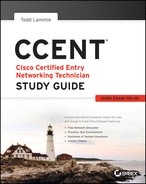
Because OSPF is the first link-state routing protocol that most people run into, it’s a good idea to size it up against more traditional distance-vector protocols like RIPv2 and RIPv1. Table 9-1 presents a nice comparison of all three of these common protocols.
Table 9-1: OSPF and RIP comparison
I want you know that OSPF has many features beyond the few I’ve listed in Table 9-1 and all of them combine to produce a fast, scalable, robust protocol that’s also flexible enough to be actively deployed in a vast array of production networks!
One of OSPF’s most useful traits is that its design is intended to be hierarchical in use, meaning that it allows us to subdivide the larger internetwork into smaller internetworks called areas. It’s a really powerful feature that I recommend using, and I promise to show you how to do that later in the chapter.
Here are three of the biggest reasons to implement OSPF in a way that makes full use of its intentional, hierarchical design:
- To decrease routing overhead
- To speed up convergence
- To confine network instability to single areas of the network
Because free lunches are invariably hard to come by, all this wonderful functionality predictably comes at a price and doesn’t exactly make configuring OSPF any easier. But no worries—we’ll crush it!
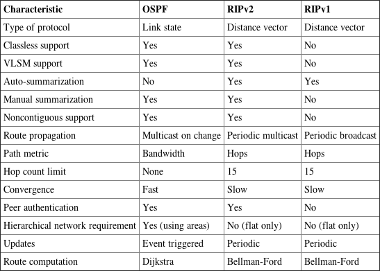
Let’s start by checking out Figure 9-1, which shows a very typical, yet simple OSPF design. I really want to point out the fact that some routers connect to the backbone—called area 0—the backbone area. OSPF absolutely must have an area 0, and all other areas should connect to it except for those connected via virtual links, which are beyond the scope of this book. A router that connects other areas to the backbone area within an AS is called an area border router (ABR), and even these must have at least one of their interfaces connected to area 0.
Figure 9-1: OSPF design example. An OSPF hierarchical design minimizes routing table entries and keeps the impact of any topology changes contained within a specific area.
OSPF runs great inside an autonomous system, but it can also connect multiple autonomous systems together. The router that connects these ASs is called an autonomous system boundary router (ASBR). Ideally, your aim is to create other areas of networks to help keep route updates to a minimum, especially in larger networks. Doing this also keeps problems from propagating throughout the network, affectively isolating them to a single area.
But let’s pause here to cover some key OSPF terms that are really essential for you to nail down before we move on any further.
OSPF Terminology
Imagine being given a map and compass with no prior concept of east, west, north or south—not even what rivers, mountains, lakes, or deserts are. I’m guessing that without any ability to orient yourself in a basic way, your cool, new tools wouldn’t help you get anywhere but completely lost, right? This is exactly why we’re going to begin exploring OSPF by getting you solidly acquainted with a fairly long list of terms before setting out from base camp into the great unknown! Here are those vital terms to commit to memory now:
- Area ID
- Stub area flag
- Authentication password (if using one)
- Hello and Dead intervals
All of these terms play a critical role when you’re trying to understand how OSPF actually works, so again, make sure you’re familiar with each of them. Having these terms down will enable you to confidently place them in their proper context as we progress on our journey through the rest of this chapter!
OSPF Operation
Fully equipped with your newly acquired knowledge of the terms and technologies we just covered, it’s now time to delve into how OSPF discovers, propagates, and ultimately chooses routes. Once you know how OSPF achieves these tasks, you’ll understand how OSPF operates internally really well.
OSPF operation is basically divided into these three categories:
- Neighbor and adjacency initialization
- LSA flooding
- SPF tree calculation
The beginning neighbor/adjacency formation stage is a very big part of OSPF operation. When OSPF is initialized on a router, the router allocates memory for it, as well as for the maintenance of both neighbor and topology tables. Once the router determines which interfaces have been configured for OSPF, it will then check to see if they’re active and begin sending Hello packets.
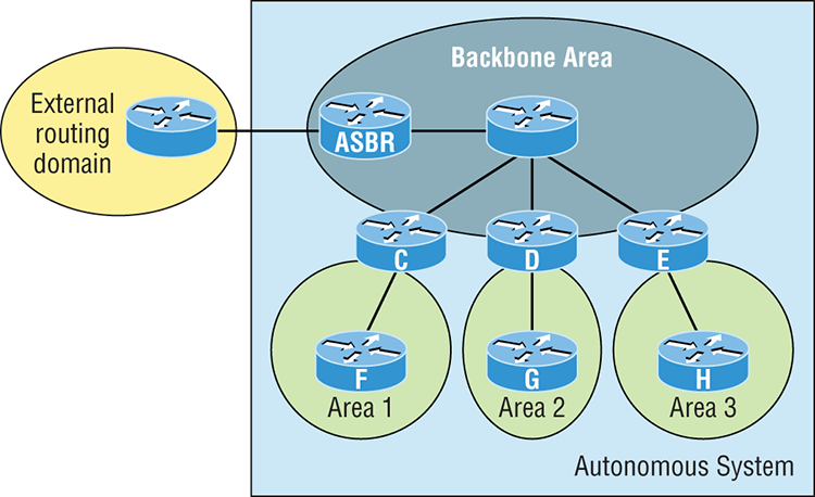
Figure 9-2: The Hello protocol
The Hello protocol is used to discover neighbors, establish adjacencies, and maintain relationships with other OSPF routers. Hello packets are periodically sent out of each enabled OSPF interface and in environments that support multicast.
The address used for this is 224.0.0.5, and the frequency with which Hello packets are sent out depends upon the network type and topology. Broadcast and point-to-point networks send Hellos every 10 seconds, whereas non-broadcast and point-to-multipoint networks send them every 30 seconds.
LSA Flooding
LSA flooding is the method OSPF uses to share routing information. Via LSU packets, LSA information containing link-state data is shared with all OSPF routers within an area. The network topology is created from the LSA updates, and flooding is used so that all OSPF routers have the same topology map to make SPF calculations with.
Efficient flooding is achieved through the use of a reserved multicast address: 224.0.0.5 (AllSPFRouters). LSA updates, which indicate that something in the topology has changed, are handled a bit differently. The network type determines the multicast address used for sending updates. Table 9-2 contains the multicast addresses associated with LSA flooding. Point-to-multipoint networks use the adjacent router’s unicast IP address.
Table 9-2: LSA update multicast addresses
| Network Type | Multicast Address | Description |
| Point-to-point | 224.0.0.5 | AllSPFRouters |
| Broadcast | 224.0.0.6 | AllDRouters |
| Point-to-multipoint | NA | NA |
Once the LSA updates have been flooded throughout the network, each recipient must acknowledge that the flooded update has been received. It’s also important for recipients to validate the LSA update.
SPF Tree Calculation
Within an area, each router calculates the best/shortest path to every network in that same area. This calculation is based upon the information collected in the topology database and an algorithm called shortest path first (SPF). Picture each router in an area constructing a tree—much like a family tree—where the router is the root and all other networks are arranged along the branches and leaves. This is the shortest path tree used by the router to insert OSPF routes into the routing table.
It’s important to understand that this tree contains only networks that exist in the same area as the router itself does. If a router has interfaces in multiple areas, then separate trees will be constructed for each area. One of the key criteria considered during the route selection process of the SPF algorithm is the metric or cost of each potential path to a network. But this SPF calculation doesn’t apply to routes from other areas.
OSPF Metrics
OSPF uses a metric referred to as cost. A cost is associated with every outgoing interface included in an SPF tree. The cost of the entire path is the sum of the costs of the outgoing interfaces along the path. Because cost is an arbitrary value as defined in RFC 2338, Cisco had to implement its own method of calculating the cost for each OSPF-enabled interface. Cisco uses a simple equation of 108/bandwidth, where bandwidth is the configured bandwidth for the interface. Using this rule, a 100 Mbps Fast Ethernet interface would have a default OSPF cost of 1 and a 1,000 Mbps Ethernet interface would have a cost of 1.
Important to note is that this value can be overridden with the ip ospf cost command. The cost is manipulated by changing the value to a number within the range of 1 to 65,535. Because the cost is assigned to each link, the value must be changed on the specific interface you want to change the cost on.
Configuring OSPF
Configuring basic OSPF isn’t as simple as configuring RIP and EIGRP, and it can get really complex once the many options that are allowed within OSPF are factored in. But that’s okay because you really only need to focus on basic, single-area OSPF configuration at this point. Coming up, I’ll show you how to configure single-area OSPF.
The two factors that are foundational to OSPF configuration are enabling OSPF and configuring OSPF areas.
Enabling OSPF
The easiest and also least scalable way to configure OSPF is to just use a single area. Doing this requires a minimum of two commands.
The first command used to activate the OSPF routing process is as follows:
Router(config)#router ospf ?
<1-65535> Process ID
A value in the range from 1 to 65,535 identifies the OSPF process ID. It’s a unique number on this router that groups a series of OSPF configuration commands under a specific running process. Different OSPF routers don’t have to use the same process ID to communicate. It’s a purely local value that doesn’t mean a lot, but you still need to remember that it cannot start at 0; it has to start at a minimum of 1.
You can have more than one OSPF process running simultaneously on the same router if you want, but this isn’t the same as running multi-area OSPF. The second process will maintain an entirely separate copy of its topology table and manage its communications independently of the first one and you use it when you want OSPF to connect multiple ASs together. Also, because the Cisco exam objectives only cover single-area OSPF with each router running a single OSPF process, that’s what we’ll focus on in this book.
Configuring OSPF Areas
After identifying the OSPF process, you need to identify the interfaces that you want to activate OSPF communications on as well as the area in which each resides. This will also configure the networks you’re going to advertise to others. OSPF uses wildcards in the configuration, which are also used in the access list configurations that we’ll cover in Chapter 12, “Security.”
Here’s an example of a basic OSPF configuration for you, showing our second minimum command needed, the network command:
Router#config t
Router(config)#router ospf 1
Router(config-router)#network 10.0.0.0 0.255.255.255 area ?
  <0-4294967295>  OSPF area ID as a decimal value
  A.B.C.D         OSPF area ID in IP address format
Router(config-router)#network 10.0.0.0 0.255.255.255 area 0Remember, the OSPF process ID number is irrelevant. It can be the same on every router on the network, or it can be different—doesn’t matter. It’s locally significant and just enables the OSPF routing on the router.
The arguments of the network command are the network number (10.0.0.0) and the wildcard mask (0.255.255.255). The combination of these two numbers identifies the interfaces that OSPF will operate on and will also be included in its OSPF LSA advertisements. Based on my sample configuration, OSPF will use this command to find any interface on the router configured in the 10.0.0.0 network and will place any interface it finds into area 0. Notice that you can create about 4.2 billion areas! In reality, a router wouldn’t let you create that many, but you can certainly name them using the numbers up to 4.2 billion. You can also label an area using an IP address format.
Let me stop here a minute to give you a quick explanation of wildcards: A 0 octet in the wildcard mask indicates that the corresponding octet in the network must match exactly. On the other hand, a 255 indicates that you don’t care what the corresponding octet is in the network number. A network and wildcard mask combination of 1.1.1.1 0.0.0.0 would match an interface configured exactly with 1.1.1.1 only, and nothing else. This is really useful if you want to activate OSPF on a specific interface in a very clear and simple way. If you insist on matching a range of networks, the network and wildcard mask combination of 1.1.0.0 0.0.255.255 would match any interface in the range of 1.1.0.0 to 1.1.255.255. Because of this, it’s simpler and safer to stick to using wildcard masks of 0.0.0.0 and identify each OSPF interface individually. Once configured, they’ll function exactly the same—one way is really isn’t better than the other.
The final argument is the area number. It indicates the area to which the interfaces identified in the network and wildcard mask portion belong. Remember that OSPF routers will become neighbors only if their interfaces share a network that’s configured to belong to the same area number. The format of the area number is either a decimal value from the range 1 to 4,294,967,295 or a value represented in standard dotted-decimal notation. For example, area 0.0.0.0 is a legitimate area and is identical to area 0.
Wildcard Example
Before getting down to configuring our network, let’s take a quick peek at a more complex OSPF network configuration to find out what our OSPF network statements would be if we were using subnets and wildcards.
In this scenario, you have a router with these four subnets connected to four different interfaces:
- 192.168.10.64/28
- 192.168.10.80/28
- 192.168.10.96/28
- 192.168.10.8/30
All interfaces need to be in area 0, so it seems to me the easiest configuration would look like this:
Test#config t
Test(config)#router ospf 1
Test(config-router)#network 192.168.10.0 0.0.0.255 area 0
Okay—I’ll admit that preceding example is actually pretty simple, but easy isn’t always best—especially when dealing with OSPF! So even though this is an easy-button way to configure OSPF, it doesn’t make good use of its capabilities and what fun is that? Worse yet, the objectives aren’t very likely to present something this simple for you! So let’s create a separate network statement for each interface using the subnet numbers and wildcards. Doing that would look something like this:
Test#config t
Test(config)#router ospf 1
Test(config-router)#network 192.168.10.64 0.0.0.15 area 0
Test(config-router)#network 192.168.10.80 0.0.0.15 area 0
Test(config-router)#network 192.168.10.96 0.0.0.15 area 0
Test(config-router)#network 192.168.10.8 0.0.0.3 area 0
Wow, now that’s a different looking config! Truthfully, OSPF would work exactly the same way as it would with the easy configuration I showed you first—but unlike the easy configuration, this one covers the objectives!
And although this looks a bit complicated, trust me, it really isn’t. All you need for clarity is to fully understand your block sizes! Just remember that when configuring wildcards, they’re always one less than the block size. A /28 is a block size of 16, so we would add our network statement using the subnet number and then add a wildcard of 15 in the interesting octet. For the /30, which is a block size of 4, we would go with a wildcard of 3. Once you practice this a few times, it gets really easy. And do practice because we’ll deal with them again when we get to access lists later on!
Let’s use Figure 9-3 as an example and configure that network with OSPF using wildcards to make sure you have a solid grip on this. The figure shows a three-router network with the IP addresses of each interface.
Figure 9-3: Sample OSPF wildcard configuration
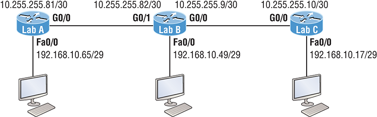
The very first thing you need to be able to do is to look at each interface and determine the subnet that the addresses are in. Hold on, I know what you’re thinking: “Why don’t I just use the exact IP addresses of the interface with the 0.0.0.0 wildcard?” Well, you can, but we’re paying attention to Cisco exam objectives here, not just what’s easiest, remember?
The IP addresses for each interface are shown in the figure. The Lab_A router has two directly connected subnets: 192.168.10.64/29 and 10.255.255.80/30. Here’s the OSPF configuration using wildcards:
Lab_A#config t
Lab_A(config)#router ospf 1
Lab_A(config-router)#network 192.168.10.64 0.0.0.7 area 0
Lab_A(config-router)#network 10.255.255.80 0.0.0.3 area 0
The Lab_A router is using a /29, or 255.255.255.248, mask on the Fa0/0 interface. This is a block size of 8, which is a wildcard of 7. The G0/0 interface is a mask of 255.255.255.252—block size of 4, with a wildcard of 3. Notice that I typed in the network number, not the interface number. You can’t configure OSPF this way if you can’t look at the IP address and slash notation and then figure out the subnet, mask, and wildcard, can you? So don’t take your exam until you can do this.
Here are other two configurations to help you practice:
Lab_B#config t
Lab_B(config)#router ospf 1
Lab_B(config-router)#network 192.168.10.48 0.0.0.7 area 0
Lab_B(config-router)#network 10.255.255.80 0.0.0.3 area 0
Lab_B(config-router)#network 10.255.255.8 0.0.0.3 area 0
Lab_C#config t
Lab_C(config)#router ospf 1
Lab_C(config-router)#network 192.168.10.16 0.0.0.7 area 0
Lab_C(config-router)#network 10.255.255.8 0.0.0.3 area 0
As I mentioned with the Lab_A configuration, you’ve got to be able to determine the subnet, mask, and wildcard just by looking at the IP address and mask of an interface. If you can’t do that, you won’t be able to configure OSPF using wildcards as I just demonstrated. So go over this until you’re really comfortable with it!
Configuring Our Network with OSPF
Okay—now we get to have some fun! Let’s configure our internetwork with OSPF using just area 0. OSPF has an administrative distance of 110, but let’s remove RIP while we’re at it because I don’t want you to get in the habit of having RIP running on your network.
There’s a bunch of different ways to configure OSPF, and as I said, the simplest and easiest is to use the wildcard mask 0.0.0.0. But I want to demonstrate that we can configure each router differently with OSPF and still come up with the exact same result. This is one reason why OSPF is more fun and challenging than other routing protocols—it gives us all a lot more ways to screw things up, which automatically provides a troubleshooting opportunity! We’ll use our network as shown in Figure 9-4 to configure OSPF and by the way, notice I added a new router!
Figure 9-4: Our new network layout
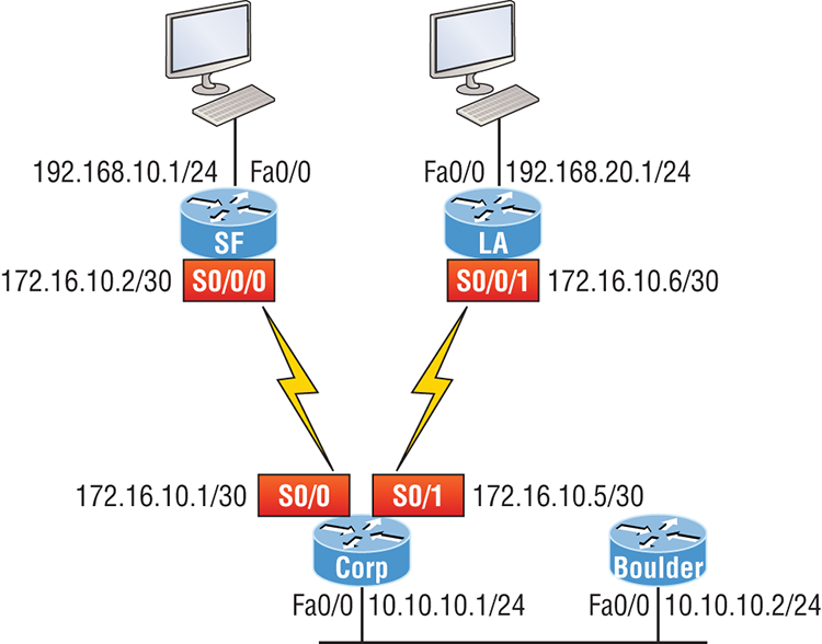
Corp
Here’s the Corp router’s configuration:
Corp#sh ip int brief
Interface        IP-Address      OK? Method Status                Protocol
FastEthernet0/0  10.10.10.1      YES manual up                    up
Serial0/0        172.16.10.1     YES manual up                    up
FastEthernet0/1  unassigned      YES unset  administratively down down
Serial0/1        172.16.10.5     YES manual up                    up
Corp#config t
Corp(config)#no router rip
Corp(config)#router ospf 132
Corp(config-router)#network 10.10.10.1 0.0.0.0 area 0
Corp(config-router)#network 172.16.10.1 0.0.0.0 area 0
Corp(config-router)#network 172.16.10.5 0.0.0.0 area 0
Alright—it looks like we have a few things to talk about here. First, I removed RIP and then added OSPF. Why did I use OSPF 132? It really doesn’t matter—the number is irrelevant. I guess it just felt good to use 132. But notice that I started with the show ip int brief command, just like when I was configuring RIP. I did this because it’s always important to verify exactly what you are directly connected to. Doing this really helps prevent typos!
The network commands are pretty straightforward. I typed in the IP address of each interface and used the wildcard mask of 0.0.0.0, which means that the IP address must precisely match each octet. This is actually one of those times where easier is better, so just do this:
Corp(config)#router ospf 132
Corp(config-router)#network 172.16.10.0 0.0.0.255 area 0
Nice—there’s only one line instead of two for the 172.16.10.0 network! I really want you to understand that OSPF will work the same here no matter which way you configure the network statement. Now, let’s move on to SF. To simplify things, we’re going to use our same sample configuration.
SF
The SF router has two directly connected networks. I’ll use the IP addresses on each interface to configure this router.
SF#sh ip int brief
Interface    IP-Address      OK? Method Status                Protocol
FastEthernet0/0  192.168.10.1    YES manual up                    up
FastEthernet0/1  unassigned      YES unset  administratively down down
Serial0/0/0      172.16.10.2     YES manual up                    up
Serial0/0/1      unassigned      YES unset  administratively down down
SF#config t
SF(config)#no router rip
SF(config)#router ospf 300
SF(config-router)#network 192.168.10.1 0.0.0.0 area 0
SF(config-router)#network 172.16.10.2 0.0.0.0 area 0
*Apr 30 00:25:43.810: %OSPF-5-ADJCHG: Process 300, Nbr 172.16.10.5 on Serial0/0/0 from LOADING to FULL, Loading Done
Here, all I did was to first disable RIP, turn on OSPF routing process 300, and then I added my two directly connected networks. Now let’s move on to LA!
LA
We’re going to give some attention to the LA router that’s directly connected to two networks:
LA#sh ip int brief
Interface    IP-Address      OK? Method Status                Protocol
FastEthernet0/0 192.168.20.1    YES manual up                    up
FastEthernet0/1 unassigned      YES unset  administratively down down
Serial0/0/0     unassigned      YES unset  administratively down down
Serial0/0/1     172.16.10.6     YES manual up                    up
LA#config t
LA(config)#router ospf 100
LA(config-router)#network 192.168.20.0 0.0.0.255 area 0
LA(config-router)#network 172.16.0.0 0.0.255.255 area 0
*Apr 30 00:56:37.090: %OSPF-5-ADJCHG: Process 100, Nbr 172.16.10.5 on Serial0/0/1 from LOADING to FULL, Loading Done
Remember that when you’re configuring dynamic routing, using the show ip int brief command first will make it all so much easier!
And don’t forget, I can use any process ID I want, as long as it’s a value from 1 to 65,535, because it doesn’t matter if all routers use the same process ID. Also, notice that I used different wildcards in this example. Doing this works really well too.
Okay, I want you to think about something for a second before we move onto more advanced OSPF topics: What if the Fa0/1 interface of the LA router was connected to a link that we didn’t want, or need to have on in order to have OSPF working, as shown in Figure 9-5?
Figure 9-5: Adding a non-OSPF network to LA router
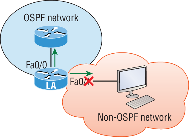
You’ve seen this before because I demonstrated this already back in Chapter 8, in the RIP section. We can use the same command that we did under that routing process here as well! Take a look:
LA(config)#router ospf 100
LA(config-router)#passive-interface fastEthernet 0/1
Even though this is pretty simple, you’ve really got to be careful before you configure this command on your router! I added this command as an example on interface Fa0/1, which happens to be an interface we’re not using in this network because I want OSPF to work on my other router’s interfaces.
Now it’s time to configure our Corp router to advertise a default route to the SF and LA routers because doing so will make our lives a lot easier. Instead of having to configure all our routers with a default route, we’ll only configure one router and then advertise that this router is the one that holds the default route—elegant!
In Figure 9-4, keep in mind that, for now, the corporate router is connected to the Internet off of Fa0/0. We’ll create a default route toward this imaginary Internet and then tell the other routers that this is the route they’ll use to get to the Internet. Here is the configuration:
Corp#config t
Corp(config)#ip route 0.0.0.0 0.0.0.0 Fa0/0
Corp(config)#router ospf 1
Corp(config-router)#default-information originate
Now, let’s check and see if our other routers have received this default route from the Corp router:
SF#show ip route
[output cut]
E1 - OSPF external type 1, E2 - OSPF external type 2
[output cut]
O*E2 0.0.0.0/0 [110/1] via 172.16.10.1, 00:01:54, Serial0/0/0
SF#
Sure enough—the last line in the SF router shows that it received the advertisement from the Corp router regarding the fact that the corporate router is the one holding the default route out of the AS.
But hold on a second! I need to configure our new router into my lab to create the example network we’ll use from here on. Here’s the configuration of the new router that I connected to the same network that the Corp router is connected to via the Fa0/0 interface:
Router#config t
Router(config)#hostname Boulder
Boulder(config)#int f0/0
Boulder(config-if)#ip address 10.10.10.2 255.255.255.0
Boulder(config-if)#no shut
*Apr  6 18:01:38.007: %LINEPROTO-5-UPDOWN: Line protocol on Interface FastEthernet0/0, changed state to up
Boulder(config-if)#router ospf 2
Boulder(config-router)#network 10.0.0.0 0.255.255.255 area 0
*Apr  6 18:03:27.267: %OSPF-5-ADJCHG: Process 2, Nbr 223.255.255.254 on FastEthernet0/0 from LOADING to FULL, Loading Done
This is all good, but I need to make sure that you don’t follow my example to a tee because here, I just quickly brought a router up without setting my passwords first. I can get away with this only because I am in a nonproduction network, so don’t do this in the real world where security is key!
Anyway, now that I have my new router nicely connected with a basic configuration, we’re going to move on to cover loopback interfaces, how to set the router ID (RID) used with OSPF, and finally, how to verify OSPF.
OSPF and Loopback Interfaces
It’s really vital to configure loopback interfaces when using OSPF. In fact, Cisco suggests using them whenever you configure OSPF on a router for stability purposes.
Loopback interfaces are logical interfaces, which means they’re virtual, software-only interfaces, not actual, physical router interfaces. A big reason we use loopback interfaces with OSPF configurations is because they ensure that an interface is always active and available for OSPF processes.
Loopback interfaces also come in very handy for diagnostic purposes as well as for OSPF configuration. Understand that if you don’t configure a loopback interface on a router, the highest active IP address on a router will become that router’s RID during bootup! Figure 9-6 illustrates how routers know each other by their router ID.
Figure 9-6: OSPF router ID (RID)
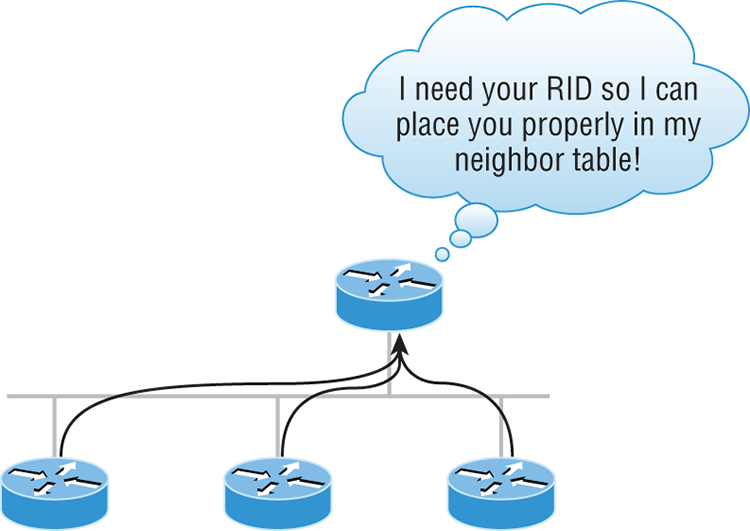
The RID is not only used to advertise routes, it’s also used to elect the designated router (DR) and the backup designated router (BDR). These designated routers create adjacencies when a new router comes up and exchanges LSAs to build topological databases.
Now it’s time to show you how to configure these logical loopback interfaces and how to verify them, as well as verify RIDs.
Configuring Loopback Interfaces
Configuring loopback interfaces rocks mostly because it’s the easiest part of OSPF configuration, and we all need a break about now—right? So hang on—we’re in the home stretch!
First, let’s see what the RID is on the Corp router with the show ip ospf command:
Corp#sh ip ospf
 Routing Process "ospf 1" with ID 172.16.10.5
[output cut]
Okay—we can see that the RID is 172.16.10.5—the Serial0/0 interface of the router. So let’s configure a loopback interface using a completely different IP addressing scheme:
Corp(config)#int loopback 0
*Mar 22 01:23:14.206: %LINEPROTO-5-UPDOWN: Line protocol on Interface
   Loopback0, changed state to up
Corp(config-if)#ip address 172.31.1.1 255.255.255.255
The IP scheme really doesn’t matter here, but each one being in a separate subnet does! By using the /32 mask, we can use any IP address we want as long as the addresses are never the same on any two routers.
Let’s configure the other routers now:
SF#config t
SF(config)#int loopback 0
*Mar 22 01:25:11.206: %LINEPROTO-5-UPDOWN: Line protocol on Interface
   Loopback0, changed state to up
SF(config-if)#ip address 172.31.1.2 255.255.255.255
Here’s the configuration of the loopback interface on LA:
LA#config t
LA(config)#int loopback 0
*Mar 22 02:21:59.686: %LINEPROTO-5-UPDOWN: Line protocol on Interface
   Loopback0, changed state to up
LA(config-if)#ip address 172.31.1.3 255.255.255.255
I’m pretty sure you’re wondering what the IP address mask of 255.255.255.255 (/32) means and why we don’t just use 255.255.255.0 instead. While it’s true that either mask works, the /32 mask is called a host mask and works fine for loopback interfaces. It also allows us to save subnets. Notice how I was able to use 172.31.1.1, .2, .3, and .4? If I didn’t use the /32, I’d have to use a separate subnet for each and every router—not good!
One important question to answer before we move on is did we actually change the RIDs of our router by setting the loopback interfaces? Let’s find out by taking a look at the Corp’s RID:
Corp#sh ip ospf
 Routing Process "ospf 1" with ID 172.16.10.5
Okay—what happened here? You would think that because we set logical interfaces, the IP addresses under them would automatically become the RID of the router, right? Well, sort of, but only if you do one of two things: either reboot the router or delete OSPF and re-create the database on your router. Neither is all that great an option, so try to remember to create your logical interfaces before you start OSPF routing. That way, the loopback interface would always become your RID straight away!
With all this in mind, I’m going with rebooting the Corp router because it’s the easier of the two options I have right now.
Now let’s look and see what our RID is:
Corp#sh ip ospf
 Routing Process "ospf 1" with ID 172.31.1.1
Okay, that did the trick! The Corp router now has a new RID, so I guess I’ll just go ahead and reboot all my routers to get their RIDs reset to our logical addresses. But should I really do that?
Maybe not because there is one other way. What do you think about adding a new RID for the router right under the router ospf process-id command instead? Sounds good, so I’d say let’s give that a shot! Here’s an example of doing that on the Corp router:
Corp#config t
Corp(config)#router ospf 1
Corp(config-router)#router-id 223.255.255.254
Reload or use "clear ip ospf process" command, for this to take effect
Corp(config-router)#do clear ip ospf process
Reset ALL OSPF processes? [no]: yes
*Jan 16 14:20:36.906: %OSPF-5-ADJCHG: Process 1, Nbr 192.168.20.1
on Serial0/1 from FULL to DOWN, Neighbor Down: Interface down
or detached
*Jan 16 14:20:36.906: %OSPF-5-ADJCHG: Process 1, Nbr 192.168.10.1
on Serial0/0 from FULL to DOWN, Neighbor Down: Interface down
or detached
*Jan 16 14:20:36.982: %OSPF-5-ADJCHG: Process 1, Nbr 192.168.20.1
on Serial0/1 from LOADING to FULL, Loading Done
*Jan 16 14:20:36.982: %OSPF-5-ADJCHG: Process 1, Nbr 192.168.10.1
on Serial0/0 from LOADING to FULL, Loading Done
Corp(config-router)#do sh ip ospf
 Routing Process "ospf 1" with ID 223.255.255.254
Now look at that—it worked! We changed the RID without reloading the router! But wait—remember, we set a logical loopback interface earlier. Does that mean the loopback interface will win over the router-id command? Well, we can see our answer… A loopback interface will not override the router-id command, and we don’t have to reboot the router to make it take effect as the RID!
So this process follows this hierarchy:
The only thing left now is to decide whether you want to advertise the loopback interfaces under OSPF. There are pros and cons to using an address that won’t be advertised versus using an address that will be. Using an unadvertised address saves on real IP address space, but the address won’t appear in the OSPF table, which means you can’t ping it.
So basically, what you’re faced with here is a choice that equals a trade-off between the ease of debugging the network and conservation of address space—what to do? A really tight strategy is to use a private IP address scheme as I did. Do this and all will be well!
Now that we’ve configured all the routers with OSPF, what’s next? Miller time? Nope—not yet. It’s that verification thing again. We still have to make sure that OSPF is really working, and that’s exactly what we’re going to do next.
Verifying OSPF Configuration
There are several ways to verify proper OSPF configuration and operation, so next, I’m going to demonstrate the various OSPF show commands you need to know in order to achieve this. We’re going to start by taking a quick look at the routing table of the Corp router.
First, let’s issue a show ip route command on the Corp router:
O    192.168.10.0/24 [110/65] via 172.16.10.2, 1d17h, Serial0/0
     172.131.0.0/32 is subnetted, 1 subnets
    172.131.0.0/32 is subnetted, 1 subnets
C        172.131.1.1 is directly connected, Loopback0
     172.16.0.0/30 is subnetted, 4 subnets
C       172.16.10.4 is directly connected, Serial0/1
L       172.16.10.5/32 is directly connected, Serial0/1
C       172.16.10.0 is directly connected, Serial0/0
L       172.16.10.1/32 is directly connected, Serial0/0
O    192.168.20.0/24 [110/65] via 172.16.10.6, 1d17h, Serial0/1
     10.0.0.0/24 is subnetted, 2 subnets
C       10.10.10.0 is directly connected, FastEthernet0/0
L       10.10.10.1/32 is directly connected, FastEthernet0/0
The Corp router shows only two dynamic routes for the internetwork, with the O representing OSPF internal routes. The Cs are clearly our directly connected networks, and our two remote networks are showing up too—nice! Notice the 110/65, which is our administrative distance/metric.
Now that’s a really sweet-looking OSPF routing table! It’s important to make it easier to troubleshoot and fix an OSPF network, which is why I always use the show ip int brief command when configuring my routing protocols. It’s very easy to make little mistakes with OSPF, so keep your eyes on the details!
It’s time to show you all the OSPF verification commands that you need in your toolbox for now.
The show ip ospf Command
The show ip ospf command is what you’ll need to display OSPF information for one or all OSPF processes running on the router. Information contained therein includes the router ID, area information, SPF statistics, and LSA timer information. Let’s check out the output from the Corp router:
Corp#sh ip ospf
 Routing Process "ospf 1" with ID 223.255.255.254
 Start time: 00:08:41.724, Time elapsed: 2d16h
 Supports only single TOS(TOS0) routes
 Supports opaque LSA
 Supports Link-local Signaling (LLS)
 Supports area transit capability
 Router is not originating router-LSAs with maximum metric
 Initial SPF schedule delay 5000 msecs
 Minimum hold time between two consecutive SPFs 10000 msecs
 Maximum wait time between two consecutive SPFs 10000 msecs
 Incremental-SPF disabled
 Minimum LSA interval 5 secs
 Minimum LSA arrival 1000 msecs
 LSA group pacing timer 240 secs
 Interface flood pacing timer 33 msecs
 Retransmission pacing timer 66 msecs
 Number of external LSA 0. Checksum Sum 0x000000
 Number of opaque AS LSA 0. Checksum Sum 0x000000
 Number of DCbitless external and opaque AS LSA 0
 Number of DoNotAge external and opaque AS LSA 0
 Number of areas in this router is 1. 1 normal 0 stub 0 nssa
 Number of areas transit capable is 0
 External flood list length 0
 IETF NSF helper support enabled
 Cisco NSF helper support enabled
    Area BACKBONE(0)
        Number of interfaces in this area is 3
        Area has no authentication
        SPF algorithm last executed 00:11:08.760 ago
        SPF algorithm executed 5 times
        Area ranges are
        Number of LSA 6. Checksum Sum 0x03B054
        Number of opaque link LSA 0. Checksum Sum 0x000000
        Number of DCbitless LSA 0
        Number of indication LSA 0
        Number of DoNotAge LSA 0
        Flood list length 0
Notice the router ID (RID) of 223.255.255.254, which is the highest IP address configured on the router. Hopefully, you also noticed that I set the RID of the corporate router to the highest available IP address available with IPv4.
The show ip ospf database Command
Using the show ip ospf database command will give you information about the number of routers in the internetwork (AS) plus the neighboring router’s ID—the topology database I mentioned earlier. Unlike the show ip eigrp topology command, this command reveals the OSPF routers, but not each and every link in the AS like EIGRP does.
The output is broken down by area. Here’s a sample output, again from Corp:
Corp#sh ip ospf database
                OSPF Router with ID (223.255.255.254) (Process ID 1)
Router Link States (Area 0)
Link ID         ADV Router      Age         Seq#       Checksum Link count
10.10.10.2      10.10.10.2      966         0x80000001 0x007162 1
172.31.1.4      172.31.1.4      885         0x80000002 0x00D27E 1
192.168.10.1    192.168.10.1    886         0x8000007A 0x00BC95 3
192.168.20.1    192.168.20.1    1133        0x8000007A 0x00E348 3
223.255.255.254 223.255.255.254 925         0x8000004D 0x000B90 5
Net Link States (Area 0)
Link ID         ADV Router      Age         Seq#       Checksum
10.10.10.1      223.255.255.254 884         0x80000002 0x008CFE
You can see all the routers and the RID of each router—the highest IP address on each of them. For example, the Link ID and ADV Router of my new Boulder router shows up twice: once with the directly connected IP address (10.10.10.2) and as the RID that I set under the OSPF process (172.31.1.4).
The router output shows the link ID—remember that an interface is also a link—and the RID of the router on that link under the ADV router, or advertising router.
The show ip ospf interface Command
The show ip ospf interface command reveals all interface-related OSPF information. Data is displayed about OSPF information for all OSPF-enabled interfaces or for specified interfaces. I’ll highlight some of the more important factors for you. Check it out:
Corp#sh ip ospf int f0/0
FastEthernet0/0 is up, line protocol is up
  Internet Address 10.10.10.1/24, Area 0
Process ID 1, Router ID 223.255.255.254, Network Type BROADCAST, Cost: 1
  Transmit Delay is 1 sec, State DR, Priority 1
Designated Router (ID) 223.255.255.254, Interface address 10.10.10.1
Backup Designated router (ID) 172.31.1.4, Interface address 10.10.10.2
  Timer intervals configured, Hello 10, Dead 40, Wait 40, Retransmit 5
    oob-resync timeout 40
    Hello due in 00:00:08
  Supports Link-local Signaling (LLS)
  Cisco NSF helper support enabled
  IETF NSF helper support enabled
  Index 3/3, flood queue length 0
  Next 0x0(0)/0x0(0)
  Last flood scan length is 1, maximum is 1
  Last flood scan time is 0 msec, maximum is 0 msec
  Neighbor Count is 1, Adjacent neighbor count is 1
    Adjacent with neighbor 172.31.1.  Suppress hello for 0 neighbor(s)
Okay—so this command has given us the following information:
- Interface IP address
- Area assignment
- Process ID
- Router ID
- Network type
- Cost
- Priority
- DR/BDR election information (if applicable)
- Hello and Dead timer intervals
- Adjacent neighbor information
The reason I used the show ip ospf interface f0/0 command is because I knew that there would be a designated router elected on the FastEthernet broadcast multi-access network between our Corp and Boulder routers. The information that I highlighted is all very important, so make sure you’ve noted it! A good question to ask you here is what are the Hello and Dead timers set to by default?
Type in the show ip ospf interface command and receive this response:
Corp#sh ip ospf int f0/0
%OSPF: OSPF not enabled on FastEthernet0/0
This error occurs when OSPF is enabled on the router, but not the interface. When this happens, you need to check your network statements because it means that the interface you’re trying to verify is not in your OSPF process!
The show ip ospf neighbor Command
The show ip ospf neighbor command is super-useful because it summarizes the pertinent OSPF information regarding neighbors and the adjacency state. If a DR or BDR exists, that information will also be displayed. Here’s a sample:
Corp#sh ip ospf neighbor
Neighbor ID     Pri   State      Dead Time   Address         Interface
172.31.1.4        1   FULL/BDR   00:00:34    10.10.10.2     FastEthernet0/0
192.168.20.1      0   FULL/  -   00:00:31    172.16.10.6     Serial0/1
192.168.10.1 0 FULL/ - 00:00:32 172.16.10.2 Serial0/0This is a critical command to understand because it’s extremely useful in production networks. Let’s take a look at the Boulder router output:
Boulder>sh ip ospf neighbor
Neighbor ID     Pri   State    Dead Time   Address         Interface
223.255.255.254   1   FULL/DR  00:00:31    10.10.10.1      FastEthernet0/0
Okay—here we can see that since there’s an Ethernet link (broadcast multi-access) on the link between the Boulder and the Corp router, there’s going to be an election to determine who will be the designated router (DR) and who will be the backup designated router (BDR). We can see that the Corp became the designated router, and it won because it had the highest IP address on the network—the highest RID.
Now the reason that the Corp connections to SF and LA don’t have a DR or BDR listed in the output is that by default, elections don’t happen on point-to-point links and they show FULL/ - . But we can still determine that the Corp router is fully adjacent to all three routers from its output.
The show ip protocols Command
The show ip protocols command is also highly useful, whether you’re running OSPF, EIGRP, RIP, BGP, IS-IS, or any other routing protocol that can be configured on your router. It provides an excellent overview of the actual operation of all currently running protocols!
Check out the output from the Corp router:
Corp#sh ip protocols
Routing Protocol is "ospf 1"
  Outgoing update filter list for all interfaces is not set
  Incoming update filter list for all interfaces is not set
Router ID 223.255.255.254
  Number of areas in this router is 1. 1 normal 0 stub 0 nssa
  Maximum path: 4
  Routing for Networks:
10.10.10.1 0.0.0.0 area 0
    172.16.10.1 0.0.0.0 area 0
    172.16.10.5 0.0.0.0 area 0
 Reference bandwidth unit is 100 mbps
  Routing Information Sources:
    Gateway         Distance      Last Update
    192.168.10.1         110      00:21:53
    192.168.20.1         110      00:21:53
  Distance: (default is 110) Distance: (default is 110)
From looking at this output, you can determine the OSPF process ID, OSPF router ID, type of OSPF area, networks and areas configured for OSPF, and the OSPF router IDs of neighbors—that’s a lot. It’s super-efficient!
Summary
This chapter gave you a great deal of information about OSPF. It’s really difficult to include everything about OSPF because so much of it falls outside the scope of this chapter and book, but I’ve given you a few tips here and there, so you’re good to go—as long as you make sure you’ve got what I presented to you dialed in, that is!
I talked about a lot of OSPF topics, including terminology, operations, and configuration as well as verification and monitoring.
Each of these topics encompasses quite a bit of information—the terminology section just scratched the surface of OSPF. But you’ve got the goods you really need for your studies. Finally, I gave you a tight survey of commands highly useful for observing the operation of OSPF so you can verify that things are moving along as they should. So eat it all up, and you’re set!
Exam Essentials
Written Lab 9
The answers to this lab can be found in Appendix A, “Answers to Written Labs.”
Hands-on Labs
In this section, you will use the following network and add OSPF routing.
The first lab (Lab 9.1) requires you to configure three routers for OSPF and then view the configuration. Note that the labs in this chapter were written to be used with real equipment—but they can be used with any router simulator. You can replace the WAN links with Ethernet links if you want to.
The labs in this chapter are as follows:
Table 9-5 shows our IP addresses for each router (each interface uses a /24 mask).
Table 9-5: Our IP addresses
| Router | Interface | IP address |
| Lab_A | Fa0/0 | 172.16.10.1 |
| Lab_A | S0/0 | 172.16.20.1 |
| Lab_B | S0/2 | 172.16.20.2 |
| Lab_B | S0/1 | 172.16.30.1 |
| Lab_C | S0/0 | 172.16.30.2 |
| Lab_C | Fa0/0 | 172.16.40.1 |
Hands-on Lab 9.1: Enabling the OSPF Process
This is the first mandatory step in OSPF configuration.
Lab_A#conf t
Enter configuration commands, one per line.
  End with CNTL/Z.
Lab_A (config)#router ospf 100
Lab_A (config-router)#^ZLab_B#conf t
Enter configuration commands, one per line.
End with CNTL/Z.
Lab_B (config)#router ospf 101
Lab_B (config-router)#^ZLab_C#conf t
Enter configuration commands, one per line.
End with CNTL/Z.
Lab_C (config)#router ospf 102
Lab_C (config-router)#^ZHands-on Lab 9.2: Configuring OSPF Interfaces
The second mandatory step in OSPF is adding your network statements.
Lab_A#conf t
Enter configuration commands, one per line.
  End with CNTL/Z.
Lab_A (config)#router ospf 100
Lab_A (config-router)#network 172.16.10.1 0.0.0.0 area 0
Lab_A (config-router)#network 172.16.20.1 0.0.0.0 area 0
Lab_A (config-router)#^Z
Lab_A #Lab_B#conf t
Enter configuration commands, one per line.
End with CNTL/Z.
Lab_B(config)#router ospf 101
Lab_B(config-router)#network 172.16.20.2 0.0.0.0 area 0
Lab_B(config-router)#network 172.16.30.1 0.0.0.0 area 0
Lab_B(config-router)#^Z
Lab_B #Lab_C#conf t
Enter configuration commands, one per line.
End with CNTL/Z.
Lab_C(config)#router ospf 102
Lab_C(config-router)#network 172.16.30.2 0.0.0.0 area 0
Lab_C(config-router)#network 172.16.40.1 0.0.0.0 area 0
Lab_C(config-router)#^Z
Lab_C#Hands-on Lab 9.3: Verifying OSPF Operation
You need to be able to verify what you configure.
Lab_A#sho ip ospf neigLab_A#sho ip routeLab_A#sho ip protocolsLab_A#sho ip ospfLab_A#sho ip ospf int f0/0Review Questions
The answers to these questions can be found in Appendix B, “Answers to Chapter Review Questions.”
1. There are three possible routes for a router to reach a destination network. The first route is from OSPF with a metric of 782. The second route is from RIPv2 with a metric of 4. The third is from EIGRP with a composite metric of 20514560. Which route will be installed by the router in its routing table?
A. RIPv2
B. EIGRP
C. OSPF
D. All three
2. In the accompanying diagram, which of the routers must be ABRs? (Choose all that apply.)
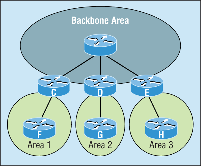
A. C
B. D
C. E
D. F
E. G
F. H
3. Which of the following describe the process identifier that is used to run OSPF on a router? (Choose two.)
A. It is locally significant.
B. It is globally significant.
C. It is needed to identify a unique instance of an OSPF database.
D. It is an optional parameter required only if multiple OSPF processes are running on the router.
E. All routes in the same OSPF area must have the same process ID if they are to exchange routing information.
4. All of the following must match for two OSPF routers to become neighbors except which?
A. Area ID
B. Router ID
C. Stub area flag
D. Authentication password if using one
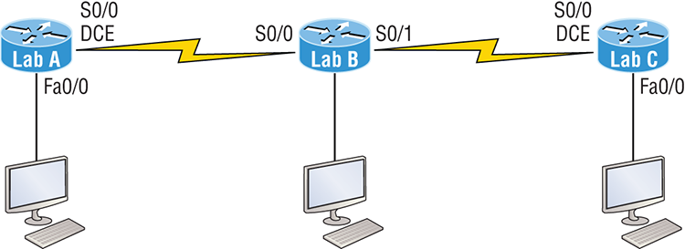
5. In the diagram, by default what will be the router ID of Lab_B?

A. 10.255.255.82
B. 10.255.255.9
C. 192.168.10.49
D. 10.255.255.81
6. You get a call from a network administrator who tells you that he typed the following into his router:
Router(config)#router ospf 1
Router(config-router)#network 10.0.0.0 255.0.0.0 area 0
He tells you he still can’t see any routes in the routing table. What configuration error did the administrator make?
A. The wildcard mask is incorrect.
B. The OSPF area is wrong.
C. The OSPF process ID is incorrect.
D. The AS configuration is wrong.
7. Which of the following statements is true with regard to the output shown?
Corp#sh ip ospf neighborNeighbor ID Pri State Dead Time Address Interface
172.31.1.4        1   FULL/BDR   00:00:34    10.10.10.2     FastEthernet0/0
192.168.20.1      0   FULL/  -   00:00:31    172.16.10.6     Serial0/1
192.168.10.1      0   FULL/  -   00:00:32    172.16.10.2     Serial0/0
A. There is no DR on the link to 192.168.20.1.
B. The Corp router is the BDR on the link to 172.31.1.4.
C. The Corp router is the DR on the link to 192.168.20.1.
D. The link to 192.168.10.1 is Active.
8. What is the administrative distance of OSPF?
A. 90
B. 100
C. 120
D. 110
9. In OSPF, Hellos are sent to what IP address?
A. 224.0.0.5
B. 224.0.0.9
C. 224.0.0.10
D. 224.0.0.1
10. What command generated the following output?
172.31.1.4 1 FULL/BDR 00:00:34 10.10.10.2 FastEthernet0/0
192.168.20.1 0 FULL/ - 00:00:31 172.16.10.6 Serial0/1
192.168.10.1 0 FULL/ - 00:00:32 172.16.10.2 Serial0/0A. show ip ospf neighbor
B. show ip ospf database
C. show ip route
D. show ip ospf interface
11. Updates addressed to 224.0.0.6 are destined for which type of OSPF router?
A. DR
B. ASBR
C. ABR
D. All OSPF routers
12. For some reason, you cannot establish an adjacency relationship on a common Ethernet link between two routers. Looking at this output, what is the cause of the problem?
RouterA#
Ethernet0/0 is up, line protocol is up
  Internet Address 172.16.1.2/16, Area 0
  Process ID 2, Router ID 172.126.1.2, Network Type BROADCAST, Cost: 10
  Transmit Delay is 1 sec, State DR, Priority 1
  Designated Router (ID) 172.16.1.2, interface address 172.16.1.1
  No backup designated router on this network
  Timer intervals configured, Hello 5, Dead 20, Wait 20, Retransmit 5
RouterB#
Ethernet0/0 is up, line protocol is up
  Internet Address 172.16.1.1/16, Area 0
  Process ID 2, Router ID 172.126.1.1, Network Type BROADCAST, Cost: 10
  Transmit Delay is 1 sec, State DR, Priority 1
  Designated Router (ID) 172.16.1.1, interface address 172.16.1.2
  No backup designated router on this network
  Timer intervals configured, Hello 10, Dead 40, Wait 40, Retransmit 5
A. The OSPF area is not configured properly.
B. The priority on RouterA should be set higher.
C. The cost on RouterA should be set higher.
D. The Hello and Dead timers are not configured properly.
E. A backup designated router needs to be added to the network.
F. The OSPF process ID numbers must match.
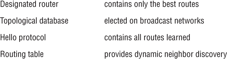
13. In the work area match each OSPF term (by line) to its definition.
14. Type the command that will disable OSPF on the Fa0/1 interface under the routing process. Write only the command and not the prompt.
15. Which two of the following commands will place network 10.2.3.0/24 into area 0? (Choose two.)
A. router eigrp 10
B. router ospf 10
C. router rip
D. network 10.0.0.0
E. network 10.2.3.0 255.255.255.0 area 0
F. network 10.2.3.0 0.0.0.255 area0
G. network 10.2.3.0 0.0.0.255 area 0
16. Given the following output, which statement or statements can be determined to be true? (Choose all that apply.)
RouterA2# show ip ospf neighbor
Neighbor ID Pri State Dead Time Address Interface
192.168.23.2 1 FULL/BDR 00:00:29 10.24.4.2 FastEthernet1/0
192.168.45.2 2 FULL/BDR 00:00:24 10.1.0.5 FastEthernet0/0
192.168.85.1 1 FULL/- 00:00:33 10.6.4.10 Serial0/1
192.168.90.3 1 FULL/DR 00:00:32 10.5.5.2 FastEthernet0/1
192.168.67.3 1 FULL/DR 00:00:20 10.4.9.20 FastEthernet0/2
192.168.90.1 1 FULL/BDR 00:00:23 10.5.5.4 FastEthernet0/1
<<output omitted>>
A. The DR for the network connected to Fa0/0 has an interface priority higher than 2.
B. This router (A2) is the BDR for subnet 10.1.0.0.
C. The DR for the network connected to Fa0/1 has a router ID of 10.5.5.2.
D. The DR for the serial subnet is 192.168.85.1.
17. What are three reasons for creating OSPF in a hierarchical design? (Choose three.)
A. To decrease routing overhead
B. To speed up convergence
C. To confine network instability to single areas of the network
D. To make configuring OSPF easier
18. Type the command that produced the following output. Write only the command and not the prompt.
FastEthernet0/0 is up, line protocol is up
  Internet Address 10.10.10.1/24, Area 0
  Process ID 1, Router ID 223.255.255.254, Network Type BROADCAST, Cost: 1 Transmit Delay is 1 sec, State DR, Priority 1
  Designated Router (ID) 223.255.255.254, Interface address 10.10.10.1
Backup Designated router (ID) 172.31.1.4, Interface address 10.10.10.2
Timer intervals configured, Hello 10, Dead 40, Wait 40, Retransmit 5
    oob-resync timeout 40
    Hello due in 00:00:08
  Supports Link-local Signaling (LLS)
  Cisco NSF helper support enabled
  IETF NSF helper support enabled
  Index 3/3, flood queue length 0
  Next 0x0(0)/0x0(0)
  Last flood scan length is 1, maximum is 1
  Last flood scan time is 0 msec, maximum is 0 msec
  Neighbor Count is 1, Adjacent neighbor count is 1
    Adjacent with neighbor 172.31.1.  Suppress hello for 0 neighbor(s)
19. A(n) ____________is an OSPF data packet containing link-state and routing information that are shared among OSPF routers.
A. LSA
B. TSA
C. Hello
D. SPF
20. If routers in a single area are configured with the same priority value, what value does a router use for the OSPF router ID in the absence of a loopback interface?
A. The lowest IP address of any physical interface
B. The highest IP address of any physical interface
C. The lowest IP address of any logical interface
D. The highest IP address of any logical interface