This chapter covers the following Cisco-specified objectives for the “Implement a small routed network” section of the 640-822 ICND1 exam:
<objective>Access and utilize the router CLI to set basic parameters
</objective> <objective>Connect, configure, and verify operation status of a device interface
</objective> <objective>Verify device configuration and network connectivity using ping, traceroute, telnet, SSH, or other utilities
</objective> <objective>Manage IOS configuration files (including: save, edit, upgrade, restore)
</objective> <objective>Manage Cisco IOS
</objective> <objective>Implement password and physical security
</objective> <objective>Verify network status and router operation using basic utilities (including: ping, traceroute, telnet, SSH, arp, ipconfig), SHOW & DEBUG commands
</objective> <objective>Configure, verify, and troubleshoot DHCP and DNS operation on a router (including: CLI/SDM)
</objective> <objective>Implement static and dynamic addressing services for hosts in a LAN environment
</objective> </feature><feature><title>Outline</title>242 | |||
242 | |||
242 | |||
244 | |||
244 | |||
245 | |||
246 | |||
247 | |||
248 | |||
248 | |||
250 | |||
250 | |||
253 | |||
254 | |||
255 | |||
255 | |||
256 | |||
256 | |||
258 | |||
259 | |||
260 | |||
261 | |||
263 | |||
263 | |||
264 | |||
266 | |||
269 | |||
272 | |||
276 | |||
277 | |||
278 | |||
281 | |||
282 | |||
284 | |||
284 | |||
285 | |||
286 | |||
289 | |||
290 | |||
291 | |||
Read the information presented in the chapter, paying special attention to tables, Notes, and Exam Alerts.
As you are reading through each section, keep in mind on which level of Cisco IOS Software these commands exist.
If possible, practice the syntax of every command discussed throughout this chapter (and book) with real or simulated Cisco equipment.
Pay close attention to the functionality associated with these commands. It is tempting to focus too hard on the command syntax itself, which ultimately makes you lose focus on the reason you are learning about the command in the first place. The ICND1 exam tests you on both why you are typing the command and how to type it.
Complete the Challenge Exercises throughout the chapter and the Exercises at the end of the chapter. The exercises will solidify the concepts that you have learned in the previous sections.
Complete the Exam Questions at the end of the chapter. They are designed to simulate the type of questions you will be asked in the ICND1 exam.
Now that you have a firm understanding how to navigate Cisco IOS Software, it is time to put that knowledge to the test by exposing yourself to the huge number of commands that are available for configuration and verification. This chapter is specifically arranged to ensure that you understand on which layer of Cisco IOS navigation hierarchy each command resides. With the chapter divided into these sections, you will learn to apply these commands correctly if presented with a Cisco configuration objective for the exam and the real world. Additionally, you should notice similarities and form an association between the syntax and functionality of the commands and the level of IOS to which they can be applied and utilized. Having this knowledge at your fingertips will prove invaluable when configuring simulations or eliminating distracting answers on the ICND1 exam.
Objective:
Access and utilize the router CLI to set basic parameters
Manage Cisco IOS
As mentioned in the Chapter 7, “Foundation Cisco IOS Operations,” Global Configuration commands affect the entire router or switch’s operations. Recall also that you enter Global Configuration by typing configure terminal from Privileged EXEC, which changes the prompt to Router(config)# or Switch(config)#. This section looks at the syntax and functions of some basic Global Configuration parameters that you can configure in a switch or a router.
Note
The majority of configuration command discussed throughout this entire book can be negated or removed if you type the keyword no, followed by the command again. The same syntax rules must apply when removing the command (you must type the command correctly and you must be in the correct level of the IOS hierarchy where the original command exists).
The previous chapter discussed two means of altering the default boot sequence of a router. Namely, you learned that by changing certain fields in the configuration register, you can force the Cisco device to perform actions such as booting from ROM and ignoring the startup configuration. In Global Configuration, the config-register command enables you to manipulate those fields and ultimately change the normal default operations of the router or switch.
For example, if you wanted to manipulate the configuration register to enter ROMmon on the next reboot, the Global Configuration command would look like this on a router:
Router(config)#config-register 0x2100On the next boot, this router instructs the bootstrap to immediately boot into ROMMon in ROM. The prompt displays rommon 1 >, signifying that the manipulation was successful and you are indeed in the mini-IOS.
Caution
Don’t Change Configuration Register Fields Unless Necessary In this book, we mention only a couple of the boot field values and the configuration field values. Do not randomly experiment with the configuration register to see the outcome. You could very well change a configuration parameter that will cause the router or switch to boot abnormally, change the console speed (leaving you guessing what speed you need to use to get terminal connectivity), or not boot at all.
If you accidentally change these settings, you can try to change the configuration register back by forcing the device to go directly to ROMmon mode on boot-up. From a console connection, turn on the device and send a break sequence (Ctrl+Break Key in HyperTerminal) from your terminal window in the first 60 seconds. You see the rommon 1 > prompt, indicating that you are in ROM Monitor. From here, enter the following command:
rommon 1 >confreg 0x2102You should see a response similar to the following:
You must reset or power cycle for new config to take effect
rommon 2 >
At this point, you can recycle the power on the device or type the ROMmon-specific command, reset, to reboot the device because you have restored the default configuration register to ensure normal operations.
The second Global Configuration command to globally affect the startup sequence that was mentioned in the previous chapter is the boot system command. With this command, you can optionally instruct the bootstrap to boot from specific locations, and even tell it which file to load if there are multiple IOS files at that location. Two different examples of the boot system commands are as follows:
Router(config)#boot system tftp c2600-do3s-mz.120-5.T1 172.16.1.1
Router(config)#boot system flash c2600-do3s-mz.120-5.T1
The first command instructs the bootstrap to locate the IOS on the TFTP server located at 172.16.1.1. The second boot system command configures the bootstrap to specifically load the IOS file c2600-do3s-mz.120-5.T1 in the possible event that Flash has multiple IOS image files on it. In examples where you have multiple boot system commands in a sequence, such as the example just given, the bootstrap tests each command in successive order until it successfully locates and loads an IOS.
Throughout this and the last chapter, you saw that the default prompt for a router starts with the hostname Router. You should change the hostname to uniquely identify the Cisco device in your internetwork. This is especially useful if you are using Telnet to remotely manage multiple devices and you need to identify to which device you are connected. The syntax for the command to change the hostname of the Cisco device is hostname, followed by the name you have chosen (up to 25 characters) as illustrated here:
Router(config)#hostname CCNA2811
CCNA2811(config)#
Notice that once we type the hostname command, the prompt immediately is changed to its new hostname (in this case, CCNA2811).
It is advisable to display a login banner as a means to provide notice of acceptable use or as a warning to anyone attempting to gain unauthorized access to your Cisco device. In Cisco terms, this is known as the message of the day. This message is displayed to any user attempting to gain an EXEC session on all terminal lines in the IOS. An example configuration for the message of the day is as follows:
CCNA2811(config)#banner motd # This is a private system and may be accessed only by
authorized users.  Unauthorized access is strictly prohibited and will be enforced to the
 full extent of the law.#
authorized users. Unauthorized access is strictly prohibited and will be enforced to the
full extent of the law.#Notice that the banner motd (message of the day) command example contains a # character before and after the message. This is known as a delimiting character and is used to inform the IOS where your banner begins and ends. This can be any character, so it makes sense to use a character that is not present in the banner itself. For instance, if the delimiting character were “v”, the banner would be displayed as This is a pri.
Caution
No Need for a Warm Welcome Be extremely careful of the message that you choose in your login banner. A login banner can be useful if you need to seek legal action against an intruder to your Cisco device. On the flip side, however, the wrong login banner can work against you. For example, if your login contains the word “welcome” or similar inviting words, this can be used as grounds for defense for an unauthorized user to gain access because it can be considered as invitation to your device.
Implement password and physical security
Gaining access to Privileged EXEC essentially means you have access to all the functionality of the IOS, including those commands that can detrimentally affect the router or switch. With that being said, it makes sense to secure access to Privileged EXEC to ensure those who gain access are indeed skilled and authorized to do so. This is achieved in Global Configuration with the creation of an enable password, which prompts anyone attempting to access Privileged EXEC with a password that is known only by those who truly are privileged.
The command to assign a password to gain access to Privileged EXEC can be achieved with one of the following two commands:
CCNA2811(config)#enable password myenablepassword
CCNA2811(config)#enable secret mysecretpassword
Tip
Be careful not to accidentally put the additional keyword password after the enable secret command. Otherwise, your secret password would be “password,” followed by your actual password. In addition, the commands are case sensitive, so make sure you don’t accidentally put the wrong case in the command.
So what is the difference between the two commands? The enable secret password is secure because it utilizes a non-reversible one-way MD5 (Message Digest 5) cryptographic hash of the password so it cannot be deciphered by anybody who can see the configuration. On the other hand, the enable password command is in clear text and can be seen by anyone that gains access to that configuration. In practice, it is customary to utilize the enable secret command for the security that it provides over the enable password command. The following configuration demonstrates a secure enable password configuration, and the resulting prompt that occurs when you try to re-enter Privileged EXEC:
CCNA1841>enable
CCNA1841#configure terminal
Enter configuration commands, one per line.  End with CNTL/Z.
CCNA1841(config)#enable secret giforgot
CCNA1841(config)#end
CCNA1841#
*Aug 12 21:46:38.055: %SYS-5-CONFIG_I: Configured from console by console
CCNA1841#disable
CCNA1841>enable
Password:
Exam Alert
When the enable password command and the enable secret password command are used in the same configuration, the enable secret command overrides the enable password command. For example, using the preceding configuration examples, the password would be “mysecretpassword” to enter Privileged EXEC.
It is possible to encrypt the password used in the enable password command by using the following Global Configuration command:
CCNA2811(config)#service password-encryptionThis command actually encrypts all clear text passwords in your configuration, including passwords you assign to the EXEC lines (discussed later). This is useful in case anyone happens to actually see your configuration because the password cannot be distinguished visually upon initial sight. Be advised, however, that the encryption used is a Cisco proprietary encryption, which is easily broken to reveal the actual password. When choosing between this method and the enable secret method for secure Privileged EXEC, use enable secret because its encryption is exponentially stronger.
Objective:
Configure, verify, and troubleshoot DHCP and DNS operation on a router (including: CLI/SDM)
Quite often, you have to test connectivity or connect to a multitude of devices from your router or switch. Unless you have all their IP addresses memorized or you have a trusty topology map with you wherever you go, you might find it difficult to accurately recall their IP address information. To assist you when such challenges arise, the Cisco IOS can statically or dynamically support domain name resolution on the Cisco device. This way, you can refer to the devices by a recognizable hostname versus an IP address.
The command to create a static entry in the IOS configuration file is ip host. For example, given the following command:
CCNA2811(config)#ip host corerouter 172.16.1.1The IOS automatically forms a name-to-IP association in a host table so that every time you refer to corerouter, it translates that hostname to the IP of 172.16.1.1.
In instances where there are far too many devices to create individual static host entries, you might be better suited to have a DNS server keep the hostname-to-IP records. With that infrastructure in place, you can have your Cisco device use these servers for the name translation. The command to specify the DNS Server(s) (up to six) is the ip name-server command as shown here:
CCNA2811(config)#ip name-server 172.16.1.254 172.16.1.100 172.16.1.2Given the previous ip name-server command, when referencing a device by its hostname, the router will query the DNS servers with the IP addresses of 172.16.1.254, 172.16.1.100, and 172.16.1.2 to resolve that hostname to an IP address.
Domain resolution is automatically enabled on your Cisco device. If you have not configured a DNS server, it tries to resolve hostnames by sending a broadcast out all its active interfaces. This can be irksome when you accidentally type a command in User or Privileged EXEC and the IOS attempts to resolve the command thinking that it is a hostname. To disable this feature, use the following command:
CCNA2811(config)#no ip domain lookupOne final domain-specific command is to assign your Cisco device to an IP domain. This command has several purposes in a Cisco networking environment; however for our purposes, it will be crucial in enabling SSH connectivity to our Cisco device as discussed in the next section. The command to assign a default domain name to a Cisco device is ip domain-name, as demonstrated here:
CCNA2811(config)#ip domain-name examprep.comAs mentioned in Chapter 7, SSH is a secure (and Cisco preferred) method of remote access to Cisco devices because the terminal connection which uses RSA public key cryptography for authentication and encryption of the data sent over the terminal connection. Because this terminal connection utilizes encryption, two prerequisites for configuring SSH is to have IPsec (DES or 3DES) IOS feature-set on the Cisco device and have an SSH-supported terminal client such as Putty and SecureCRT.
Assuming your Cisco device meets the prerequisites for SSH, the first step in enabling SSH connectivity to the Cisco IOS is to configure a hostname (other than its default) and assign the device to a domain as previously discussed. The only remaining step in the SSH process is to generate an RSA key for the encryption. The default key length is 512 bits, however, it is recommended to have a key of at least 1024 bits in length for additional security strength. The command to generate this key is crypto key generate rsa as demonstrated here:
CCNA2811(config)#crypto key generate rsa The name for the keys will be: CCNA2811.examprep.com Choose the size of the key modulus in the range of 360 to 2048 for your General Purpose
Notice how the key generating process uses the hostname and domain name of the device when generating the key; therefore, those configuration steps must be performed first. Also notice that at the completion of the key generation, SSH is automatically enabled.
Note
Starting with Cisco IOS Software Release 12.3(4)T, Cisco IOS devices support SSH version 2. Version 2 is more flexible and addressed some active attack vulnerabilities from version 1.
One final element to the SSH configuration is to define a username and password for authentication. This username/password pair will be used when you configure your SSH client to connect to IOS. The command to define this username and password pair is username username password password in Global Configuration. For instance, if you want to use SSHusername as your username and SSHpassword as your password, the configuration would look like the following:
CCNA2811(config)#username SSHusername password SSHpasswordThis chapter previously discussed how to secure access to Privileged EXEC by using the enable password or enable secret command. However, this assumes that any administrators can still gain User EXEC to the Cisco device. The problem with this configuration is that you can send excessive pings or Telnet to another device from your router or switch in User EXEC. Because the ping and Telnet traffic are coming from your private router or switch, they might not be blocked by a security device such as a firewall. This section looks into how to secure access to the User EXEC by assigning a password on the EXEC lines into the Cisco device.
Objective:
Implement password and physical security
Console access necessitates that an admin have physical access to the device itself. If your Cisco router or switch is physically accessible to non-authorized personnel (not highly recommended), you should take preventative measures to add another level of security by having the devices prompt anybody trying to get to User EXEC via the console port for a password. The following three commands ultimately achieve that goal:
CCNA2811(config)#line console 0
CCNA2811(config-line)#login
CCNA2811(config-line)#password myconsolepassword
The first command navigates the IOS to a sub-configuration mode for the console port. The second command instructs the IOS to prompt anybody connecting to this EXEC line for a login, using the password chosen in the third command.
Tip
It does not matter if you type the password command before the login command. The important factor is that both commands are configured.
To add yet another additional level of security comfort, it is also advisable to have the IOS close the console session after so much time of inactivity (no typing) in the session. After the EXEC session is closed, the admin has to enter the console password (assuming the above console configuration was in place) to get into User EXEC again. This is generally useful for those emergency bathroom breaks that arise after a couple cups of coffee or those unscheduled fire drills.
By default, the console session closes after 10 minutes of inactivity which, unfortunately, is plenty of time for someone to jump on to your terminal and change passwords and lock you out if you are not present. To change that setting, use the exec-timeout command followed by the number of minutes and seconds the IOS should wait to time out. For example, if you want the console to close after 1 minute and 30 seconds of inactivity, the command should reflect the following:
CCNA2811(config-line)#exec-timeout 1 30Exam Alert
The exec-timeout command identifies how long the EXEC terminal session will remain active when no commands are being typed. The syntax specifies the minutes followed by the seconds.
Tip
The IOS sends all alerts and notification messages to the console port by default. Unfortunately, this sometimes interrupts the command you are typing. To make your Cisco device more polite and stop interrupting you, use the logging synchronous command. After it is configured, IOS still send a notification to the terminal session, but returns a new line to the user with the information already entered.
Implement password and physical security
If your organization has decided to allow remote terminal access to your Cisco device through an external modem or terminal server connected to the auxiliary port, you have added another means of getting to User EXEC that you must secure. The auxiliary port is slightly easier to connect than the console port because physical access is no longer a mandate. As long as you know the phone number to dial into the modem, you can gain access to a User EXEC session. This ease of access should be counterbalanced with security measures to ensure authorized users are connecting to this EXEC line.
Conveniently, the commands are practically identical to those used to secure a console connection. The only major difference is the navigation to the auxiliary port as opposed to the console:
CCNA2811(config)#line auxiliary 0
CCNA2811(config-line)#login
CCNA2811(config-line)#password myauxpassword
CCNA2811(config-line)#exec-timeout 1 30
Objectives:
Implement password and physical security
Verify device configuration and network connectivity using ping, traceroute, telnet, SSH, or other utilities
Telnet and SSH are by far the most insecure methods of establishing an EXEC session because any user with IP connectivity to the device can initiate a Telnet or SSH session to it. For this reason, the default state of these lines is to require that a vty password be set for anyone to achieve access to User EXEC. Otherwise, you will receive an error similar to the following:
Password required, but none set
In addition, if you do not have an enable password set on the device, you are not able to enter Privileged EXEC mode. The error you receive in this situation is the following:
% No password set
Exam Alert
Remember, by default a password must be set on the vty lines to give SSH and Telnet access to this device. An enable password must be set to access Privileged EXEC over a Telnet or SSH session.
Once again, the configuration is similar to those of the console and the auxiliary port; however, the navigation of the Telnet lines is slightly different than what you find with the rest. To assign a login password to all the vty lines into the device, you must specify the range of those vty lines in your navigation. For instance, most routers allow five Telnet or SSH sessions into them. To encompass all the vty lines, you have to identify them starting with the first line (remembering that numbering begins with 0), followed by the last (0-4 is a total of 5 lines), as shown here:
CCNA2811(config)#line vty 0 4
CCNA2811(config-line)#login
CCNA2811(config-line)#password mytelnetpassword
CCNA2811(config-line)#exec-timeout 1 30
The question usually begs, “What would happen if you configured only line vty 0 or you put a different password on each vty line?” To answer the first part of the question, if you configure only line vty 0, the router prompts the first user for a password. If another user tries to connect with that first Telnet session still running, he cannot log in to the router (remembering that the default state is that a password must be set as mentioned in the earlier Exam Tip).
On the other hand, if you assign different passwords to each of the vty lines, you can connect on all the lines; however, you have no means of choosing or knowing to which vty line you are connected. You would have to guess the password within three tries (IOS only allows three attempts).
Exam Alert
Be sure you are easily able to supply a configuration to any number of the EXEC lines depending on the scenario given.
Your configuration should look like the following (with possible variation on the abbreviation of the commands):
! Step 1 Router>enable Router#configure terminal Enter configuration commands, one per line. End with CNTL/Z ! Step 2 Router(config)#line console 0 Router(config-line)#login Router(config-line)#password captnstubing ! Step 3 Router(config-line)#exec-timeout 2 10 Router(config-line)#exit ! Step 4 Router(config)#line aux 0 Router(config-line)#login Router(config-line)#password bartenderisaac ! Step 5 Router(config-line)#exec-timeout 3 0 Router(config-line)#exit ! Step 6 Router(config)#line vty 0 4 Router(config-line)#login Router(config-line)#password yeomangopher Router(config-line)#exit ! Step 7 Router(config)#hostname TheLoveRouter ! Step 8 TheLoveRouter(config)#ip domain-name comeaboard.com ! Step 9 TheLoveRouter(config)#crypto key generate rsa The name for the keys will be: TheLoveRouter.comeaboard.com Choose the size of the key modulus in the range of 360 to 2048 for your General Purpose
In this configuration, anyone connecting to the console port needs to enter the password captnstubing before gaining an EXEC session via the console port. After 2 minutes and 10 seconds of inactivity, the sessions close and users have to enter in the password again to return to User EXEC. Likewise, anyone accessing the router from the auxiliary port needs to enter the password bartenderisaac at the login prompt and has to re-enter that password after 3 minutes of inactivity. Up to five administrators can Telnet or SSH into this router, at which point they all have to enter the password yeomangopher at the login prompt. RSA was enabled by using the crypto key generate rsa command and specifying the key length as 1024. The key generated used our configured IP domain, comeaboard.com, and the default hostname of Router (since that was unchanged).
Because the enable password command and the enable secret command are used in this configuration, the password something4every1 inevitably will be used to enter Privileged EXEC because the enable secret command overrides the enable password. The final command, service password-encryption, encrypts the enable, vty, aux, and console passwords so they are not visible to anyone who can see the configuration.
Objective:
Connect, configure, and verify operation status of a device interface
Because a primary purpose of Cisco routers and switches is to transfer data between their interfaces, the configuration parameters that you apply to these interfaces dramatically affect how these devices operate in an internetwork. These interface configurations vary depending on the type of interface you are configuring and even which Layer 2 frame encapsulation you are utilizing for WAN interfaces. This section looks specifically at some of the basic configurations that you can apply to LAN and WAN interfaces on a router.
Recall from Chapter 1, “Standard Internetworking Models,” that the basic functionality of a router is to forward packets from one network to another, using logical addressing. If you configure an IP address on an interface, that router systematically assumes that all packets that are destined for that IP address’s network should be routed out that specific interface. For instance, if you assign the IP address of 192.168.1.1 with a subnet mask of 255.255.255.0 on a serial interface, the router automatically assumes when that interface is enabled that all packets destined for 192.168.1.x are to be sent out the WAN serial interface.
As you can see, assigning an IP address to an interface plays a pivotal role in a router’s primary routing operation. The command to help fulfill that role on a given interface is ip address, followed by the assigned IP address for that interface and the subnet mask. For instance, if you wanted to assign the IP address of 192.168.1.1 with a subnet mask of 255.255.255.0 to the serial 0/0 interface of the 2600 modular router, the configuration would look like this:
Router(config)#interface serial 0/0
Router(config-if)#ip address 192.168.1.1 255.255.255.0
Note
Remember, if this was a router with a fixed interface (not modular), the command might look something like this:
Router(config)#interface serial 0
Router(config-if)#ip address 192.168.1.1 255.255.255.0
The first line in the configuration navigates you to the appropriate interface that you wish to configure. In this case, it is the first serial interface in the first module on the 2600 router (serial 0/0). The second command assigns the IP address of 192.168.1.1 to this interface. After this interface is enabled (discussed in next section), this router forwards any packets destined for 192.168.1.x 255.255.255.0 out its serial 0/0 interface.
Note
Because a router needs to forward packets between networks, you cannot configure two interfaces with IP addresses that are part of the same subnet. For example, you cannot configure serial 0 for 192.168.1.1 255.255.255.0 and interface ethernet 0 with an IP of 192.168.1.2 255.255.255.0. Because both IPs exist on the 192.168.1.0 network, the router cannot distinguish to which interface to send packets destined for 192.168.1.x. When a configuration error such as this is attempted, the router informs you that the IP network overlaps with another interface and does not let you assign the second IP address.
For documentation and reference, you can assign a description to this interface by using the description command on the interface:
Router(config-if)#description This is my first interface description.All router interfaces are in a disabled (shutdown) state by default. It is the duty of the configuring administrator to enable the interface by using the no shutdown command. If properly configured and connected to the network, the interface comes up and begins routing data in and out that interface. An example of administratively enabling the interface with the no shutdown command is as follows:
Router(config)#interface serial 0/0
Router(config-if)#no shutdown
Exam Alert
You should be able to seamlessly assign an IP address on any interface and administratively enable it for the exam.
Tip
If your interface is not connected to any other devices to communicate at Layer 2, you can use the no keepalives command on the interface to keep your interface active. A keepalive is a mechanism that the IOS uses to send messages to itself or to the other end to ensure a network interface is alive.
Many of the LAN interfaces on a router have auto-sensing capabilities such as duplex and speed. For instance, a Fast Ethernet interface can run at speeds of 10mbps or 100mbps at half- or full-duplex. It is generally a good idea to manually assign an interface’s duplex and speed in case your connected device does not support auto negotiation. The configuration to manually set the speed and duplex on an interface is fairly straightforward, as follows:
Router(config)#interface FastEthernet 0/0
Router(config-if)#speed 100
Router(config-if)#duplex full
When configuring synchronous serial interfaces, you may discover that you have to configure some additional parameters to ensure proper functionality of your Wide Area Network (WAN) interfaces. For instance, when you have a serial cross-over cable between two routers’ serial interfaces in a lab environment, the serial interface with the DCE cable attached to it has to provide timing for the network for data to be recognized on this link. The command to provide this synchronous timing on the network is clock rate, followed by the speed in bits per second.
Additionally, WAN serial interfaces automatically assume that the circuit connected to them is of T1 speed (1.54mbps). In instances where you have set a lower clock rate or you are connecting to a WAN service that is using sub-T1 speeds or virtual circuits (discussed later in Chapter 15, “Wide Area Network Connections”), it is imperative to redefine the bandwidth that is connected to the interface for accurate operation of routing decisions. You can achieve this redefinition by using the bandwidth command followed by the speed of the circuit in kilobits per second.
The following configuration demonstrates both of these commands in action for a router in a lab simulating a 64kbps circuit:
Router(config)#interface Serial 0/0
Router(config-if)#clock rate 64000
Router(config-if)#bandwidth 64
Objective:
Manage IOS configuration files (including: save, edit, upgrade, restore)
If you are like me, you like living on the edge by configuring your devices during scheduled brown-outs in a room full of people with size 15 feet who are prone to accidentally kick the power cord out of your Cisco device. The problem with that lifestyle is that when the power returns to your router or switch, the hard work you put into your configuration is gone because all your configurations were made to the running configuration stored in volatile RAM. This is unfortunately true, unless of course, you save your configuration file into NVRAM and make that your startup configuration.
The versatile command that deserves all this credit for saving your hides is the copy command. With this command, you are telling the IOS to copy a file from one file system to another. Some options you have after the copy command are running-config, startup-config, flash, and tftp. The last two are discussed later in this chapter; the Global Configuration command to save the configuration in a switch or router IOS is as follows:
Router(config)#copy running-config startup-configExam Alert
Cisco advises that you do not need to save the configuration in a simulation. Despite my danger-seeking lifestyle, I highly recommend you err on the safe side by saving your configuration in case this policy changes in the future.
Tip
After performing the copy running-config startup-config, later IOSs ask you for the filename that you want to call the configuration file with [startup-config] in brackets. If you hit the Enter key, it saves it as the startup-config that will be loaded on next reboot. Saving it with a different filename saves the configuration, but that configuration will not be the one that is loaded.
Exam Alert
If you want to return your router or switch to its default configuration, you can use the Privileged EXEC command, erase startup-config, and reboot the device with the reload command. After the router or switch reboots, you should enter into Setup Mode because the configuration in NVRAM was erased.
The result should look similar the following:
! Step 1
Router>enable
! Step 2
Router# configure terminal
Enter configuration commands, one per line. End with CNTL/Z
! Step 3
Router(config)# interface fastethernet 0/0
Router(config-if)# ip address 172.16.1.1 255.255.0.0
! Step 4
Router(config-if)# no shutdown
! Step 5
Router(config-if) #exit
Router(config)# interface serial 0/0
Router(config-if)# ip address 192.168.1.1 255.255.255.0
! Step 6
Router(config-if)# no shutdown
! Step 7
Router(config-if)# Router(config-if)#end
00:04:48: %SYS-5-CONFIG_I: Configured from console by console
Router# copy running-config startup-config
Destination filename [startup-config]?
Verify network status and router operation using basic utilities (including: ping, traceroute, telnet, SSH, arp, ipconfig), SHOW & DEBUG commands
As an administrator of Cisco routers and switches, it is inevitable that you will have to get information and statistics to verify the functionality of those devices and the networks that are connected to them. The crux of every command to view these statistics is the show keyword. This section explains what information you can gain from several of these show commands and tells you how to interpret outputs of those commands.
Tip
Some of the show commands will have quite a lot of extraneous output that may not be pertinent to what you are trying to discover. In some extreme cases, this can go on for pages and pages of output and you could spend quite a bit of time weeding through all the information. To assist you finding specific information, the Cisco IOS now gives you the ability to filter the output by adding a pipe symbol (|) followed by the keyword include, exclude, or begin and the expression you want to filter. Include will only show you outputs that include the expression that you define in the command. Exclude provides the exact opposite service in that it will show you all the output except for the expression you specify. Finally, begin will show you the full output beginning at the point the expression is found.
Without a doubt, verifying your configurations is one of the most widely used show functions in the Cisco IOS. What better way to double-check or troubleshoot your configuration could there be besides seeing it displayed right in front of you? One caveat to these particular show commands, however, is that you must be in Privileged EXEC to see the configurations. This makes logical sense because you don’t want anybody from User EXEC to see your passwords in the configurations.
To see the active configuration that is running in RAM (that is, running-config), simply type show running-config. Similarly, the command show startup-config displays the configuration that will be loaded after you reboot the router or switch. The following example shows the show running-config command, and the output of some of the router configurations discussed in this chapter, performed on an 1720 router with a fixed Fast Ethernet interface:
CCNA1720#show running-config
Building configuration...
Current configuration:
!
version 12.4
service timestamps debug uptime
service timestamps log uptime
service password-encryption
!
hostname CCNA1720
!
enable secret 5 $1$nLCr$gNidpLSZvMnm2wFW6ACLm0
enable password 7 14120A0A0107382A29
!
boot-start-marker
boot-end-marker
!
!
memory-size iomem 15
no aaa new-model
ip subnet-zero
ip host corerouter 172.16.1.1
ip name-server 172.16.1.254
!
!
ip cef
!
interface FastEthernet0
 ip address 172.16.1.1 255.255.0.0
 no ip directed-broadcast
 full-duplex
!
interface Serial0/0
 bandwidth 64
 ip address 192.168.1.1 255.255.255.0
 no ip directed-broadcast
 no fair-queue
!
ip classless
ip http server
!
banner motd ^C This is a private system and may be accessed only by authorized users.
 Unauthorized access is strictly prohibited and will be enforced to the full
 extent of the law.^C
!
line con 0
 exec-timeout 1 30
 password 7 045802150C2E
 login
line vty 0 4
 exec-timeout 1 30
 password 7 02050D480809
 login
!
End
Note
Notice that in the output of the show running-config command there are commands such as service timestamps debug uptime, ip subnet-zero, and so on that have not been discussed. These are all configurations that are created by default by the IOS, and may vary depending on the version of the IOS that is loaded. On that same note, some configurations do not even show up in the IOS configuration even though they are configured on the router or switch. For instance, both interfaces were administratively enabled in this configuration despite the lack of the command no shutdown being displayed on each interface configuration.
Exam Alert
One of your best resources on a simulation that has a troubleshooting scenario is the show running-config command. By looking at the configuration and recognizing incorrect or missing entries, you can determine what items must be fixed in a particular device to regain connectivity in the simulated network.
Beyond a doubt, the next four show commands will serve as the most useful tools in determining interface functionality and the performance of the network connected to those interfaces. Some of the outputs for these interface-specific show commands display similar statistics; nevertheless, each command serves a unique purpose depending on what facet of the interfaces you are trying to investigate.
The most detailed show command that displays statistics about the status of the interfaces and the network traffic for that interface is the show interfaces command. This command shows you statistics for all interfaces on the router or switch; however, if you wish to view information about only a single interface, you can specify that interface in the command (for example, show interfaces serial 0/0). The output that follows illustrates the show interface output for a Fast Ethernet interface:
Router#show interfaces FastEthernet 0/0
FastEthernet0/0 is up, line protocol is up
  Hardware is Gt96k FE, address is 001a.2f66.fa1a (bia 001a.2f66.fa1a)
  Internet address is 172.16.0.1/16
  MTU 1500 bytes, BW 100000 Kbit, DLY 100 usec,
     reliability 255/255, txload 1/255, rxload 1/255
  Encapsulation ARPA, loopback not set
  Keepalive not set
  Full-duplex, 100Mb/s, 100BaseTX/FX
  ARP type: ARPA, ARP Timeout 04:00:00
  Last input 00:00:10, output 00:00:10, output hang never
  Last clearing of "show interface" counters never
  Input queue: 0/75/0/0 (size/max/drops/flushes); Total output drops: 0
  Queueing strategy: fifo
  Output queue: 0/40 (size/max)
  5 minute input rate 0 bits/sec, 0 packets/sec
  5 minute output rate 0 bits/sec, 0 packets/sec
     322 packets input, 70336 bytes
     Received 322 broadcasts, 0 runts, 0 giants, 0 throttles
     0 input errors, 0 CRC, 0 frame, 0 overrun, 0 ignored
     0 watchdog
     0 input packets with dribble condition detected
     343 packets output, 72188 bytes, 0 underruns
     0 output errors, 0 collisions, 3 interface resets
     0 babbles, 0 late collision, 0 deferred
     0 lost carrier, 0 no carrier
     0 output buffer failures, 0 output buffers swapped out
A common statistic of most of the interface show commands is the actual status of the interface itself. This is identified in the first line of output of the show interfaces commands. The first part of the status identifies the Layer 1 information of the interface, followed by the Layer 2 line protocol status.
If you understand the interface statuses you are ultimately building a solid foundation to accurately troubleshoot any malfunctioning interface. For example, if your interface is in an “up/line protocol up” state, you have eliminated Layer 1 and Layer 2 malfunctions for that interface. From this point, you can determine whether the problem on the interface is perhaps a Layer 3 problem (IP addressing, routing, and so on). Table 8.1 lists the possible values of this command.
Table 8.1. Interface Status Values
Layer 1 | Layer 2 (line protocol) | Possible Symptoms |
|---|---|---|
Up | Up | None. Interface is functional. |
Up | Down | Encapsulation mismatch, lack of clocking on serial interfaces, missing keepalives. |
Down | Down | Cable is disconnected or attached to a shut down interface on the far-end device. |
Administratively Down | Down | Local interface was not enabled with the |
Exam Alert
Be able to recognize the interface status meanings and determine the possible reasons for that status.
The rest of the output of the show interfaces command is also extremely useful for gaining information about the interface and the network. Of course, you won’t be expected to know all the elements listed in this output; however, Table 8.2 displays some of the valuable common statistics descriptions.
Table 8.2. Show Interface Output Descriptions
Output | Description |
|---|---|
| The MAC address of the ethernet interface. |
| Assigned IP address. |
| The Maximum Transmission Unit (frame size) for this interface, logical bandwidth (default or set with |
| Layer 2 frame encapsulation on interface. |
| Duplex and speed of interface. |
| The number of broadcasts, runts (below minimum frame size), and giants (above maximum frame size). |
| The number of collisions that occurred on that segment. |
| Late collisions occur when your interface is set for half-duplex and you are connected to a full-duplex interface. |
Exam Alert
You may be presented with the output of a show interface command with the intention of testing your knowledge of being able to identify problematic elements in the output. For instance, a high load value is evidence of a saturated link, a large number of late collisions is a duplex mismatch, excessive collisions might be indicative of being plugged into a hub, and so on.
If the goal of your show command is to get a condensed output of the interfaces’ status and their IP addresses, the show ip interface brief command conveniently shows you a minimal display of these statistics as illustrated here:
Router#show ip interface brief
Interface                  IP-Address      OK? Method Status                Protocol
FastEthernet0/0            192.168.100.154 YES DHCP   up                    up
FastEthernet0/1            unassigned      YES unset  administratively down down
Serial0/0 unassigned YES unset administratively down downAlthough the output of the show controller command is unintelligible to everyone except for the Cisco TAC (Technical Assistance Center), one particularly useful extract from this output is in the show controller serial command. The needle in this haystack of statistics is the line of output that identifies whether a DTE or a DCE cable is attached to the serial interface. This is useful if you are connecting to your router remotely and you are not sure whether your router should be providing the clocking (if you are the DCE interface). The following excerpt example illustrates this useful output:
Router>show controller serial 0/1
Interface Serial0/1
Hardware is PowerQUICC MPC860
V.35 DCE cable, clockrate 64000
...output omitted...The following section discusses how to back up your IOS to a TFTP server or download a new version of the IOS to your router or switch. Tasks of this magnitude, however, cannot be performed unless you do some initial legwork. Namely, you must perform some essential steps such as identifying the amount of Flash memory, the IOS filename located in Flash, and the current IOS version that is running on the device.
Different Cisco IOS versions and feature sets will ultimately dictate the size of the IOS file and the amount of Flash and DRAM memory required to run the IOS. If you are planning to upgrade to a new IOS, you must make sure that you have enough memory (the more, the better) in your device. To see the amount of Flash you have and the current IOS file stored in Flash memory, utilize the show flash command as follows:
Router>show flash
System flash directory:
File  Length   Name/status
  1   5510192  c2600-is-mz.120-3.T3.bin
[5510256 bytes used, 2878352 available, 8388608 total]
8192K bytes of processor board System flash (Read/Write)
Typically, the filename of the IOS file in Flash correctly reflects the actual IOS version running currently on the device. However, an administrator can easily change the filename to his or her own purposes, or there could be multiple IOS files stored on the Flash and you are not sure which one is running currently. To ensure the correct version of IOS, use the widely practical show version command.
As the following output demonstrates, the show version command displays a plethora of information well beyond the version of IOS running. Table 8.3 explains some of the useful output of this multifaceted command.
Table 8.3. Show Version Output Descriptions
Output | Description |
|---|---|
| The IOS feature set, version, and release. |
| The version of the bootstrap code in ROM. |
| The length of time the device has been running. |
| How the device was started. |
| The name of the IOS file that was loaded and the location of that file. |
| The amount of RAM in the system allocated to the devices processor, followed by memory allocated for packets. The total RAM is calculated by adding the two values together |
| The amount of NVRAM for the startup-config. |
| Total amount of Flash memory. |
| The current configuration register. |
Router#show version Cisco IOS Software, 1841 Software (C1841-ADVIPSERVICESK9-M), Version 12.4(3g), RELEASE
Objectives:
Verify network status and router operation using basic utilities (including: ping, traceroute, telnet, SSH, arp, ipconfig), SHOW & DEBUG commands
Verify device configuration and network connectivity using ping, traceroute, telnet, SSH, or other utilities
Troubleshooting a Cisco device and the networks to which it is connected is an integral part of being a Cisco administrator. Most of your troubleshooting can be solved by verifying your configurations and the device’s operations, using the show commands mentioned in the previous section. However, at times you may need to use additional commands to help identify and troubleshoot faults in the network.
Specifically, the clear command in Privileged EXEC resets statistical information that is being stored for the outputs of your show commands. For example, if you saw that the output of the show interfaces serial 0/0 command and noticed excessive late collisions, how do you know whether those are recent statistics or collisions that occurred last week? Using the clear counters command resets those statistics so you can view up-to-date information from the show interfaces output.
One of the most widely utilized commands for troubleshooting is the ping command. ping uses ICMP echo and echo reply messages to verify connectivity to IP devices. To ping a specific device from User EXEC or Privileged EXEC, enter ping followed by the IP address or hostname of the device you are trying to verify, as follows:
Router#ping 192.168.1.1
Type escape sequence to abort.
Sending 5, 100-byte ICMP Echos to 192.168.1.1, timeout is 2 seconds:
.!!!!
Success rate is 80 percent (4/5)
Notice that the ping response contains a period (.) followed by four exclamation marks (!). An exclamation mark character is indicative of a successful receipt of a reply to the ping. The period character indicates that a timeout has occurred for that particular ICMP echo packet. In some instances, you may receive a U character, which signifies a Destination Unreachable ICMP message. These messages are indicative that a router along the packet’s path to the destination did not know how to reach the destination network. When this occurs, the router sends a Destination Unreachable message back to the packet’s source.
Exam Alert
ICMP Destination Unreachable messages are sent by a routing device when it does not know how to reach the destination network. The router sends this ICMP message back to the packet’s source.
Exam Alert
Notice that in the output of the ping command, the first ping packet timed out. This actually is quite normal when pinging a device on a LAN because the router or switch might have to resolve the MAC address on the data link segment with an ARP request. Any successive pings shortly after should receive 100% of replies.
Similar to other operating systems, you can manipulate some of the options in a ping echo request, such as the datagram size and the timeout period in the Cisco IOS. To specify these options, you need to use an extended ping command. This command requires you to be in Privileged EXEC and is used by typing ping followed by the Enter key (no IP address). From there, you can change the default parameters such as the datagram sizes, timeout, and the number of packets sent, as shown in the following example:
Router#ping
Target IP address: 192.168.1.1
Repeat count [5]: 10
Datagram size [100]: 200
Timeout in seconds [2]: 5
Extended commands [n]: y
Source address or interface:
Type of service [0]:
Set DF bit in IP header? [no]:
Validate reply data? [no]:
Data pattern [0xABCD]:
Loose, Strict, Record, Timestamp, Verbose[none]:
Sweep range of sizes [n]:
Type escape sequence to abort 192.168.1.1, timeout is 5 seconds:
!!!!!!!!!
Success rate is 100 percent (10/10)
Exam Alert
The extended ping must be entered in Privileged EXEC. The command is ping followed by the Enter key.
Another useful ICMP utility is the traceroute command. As the name states, traceroute sends ICMP messages and receives a reply from every routing device along the path to the destination. This is useful in situations where you suspect a router on the route to an unreachable network is failing. The command syntax for traceroute is similar to the ping command. In fact, you can also perform an extended traceroute by using the traceroute command in lieu of the ping keyword.
Router#trace 192.168.1.1
Tracing the route to 192.168.1.1
1 192.168.100.1 4 msec 0 msec 4 msec
2 10.1.1.3 4 msec 4 msec 0 msec
3 192.168.1.1 0 msec 0 msec 4 msec
Exam Alert
traceroute is an ICMP utility that tests the connectivity to a device by receiving responses from each routing device along the path to the destination. It is especially useful when you suspect a router on the route to an unreachable network is failing.
The final troubleshooting command (for now) is another exclusive Privileged EXEC command that should be used only when all other troubleshooting has failed. The debug command displays real-time information on such things as routing updates, packet forwarding, and interface keepalives, to name a few. The reason behind the cautionary tone of this explanation is because the debug command is very processor intensive and can generate a lot of information on your terminal screen. For this reason, it is highly recommended that you use these commands only in emergency situations or in a lab environment. If you must troubleshoot on a production router, be sure to issue the show processes command as follows:
RouterA#show processes
CPU utilization for five seconds: 0%/0%; one minute: 0%; five minutes: 0%
...Output Omitted...
The majority of the output will not make sense; however, the top of the output lists the CPU utilization up to the last 5 minutes. If any of these values exceeds 60%, do not use the debug commands. If you do, your router is likely to seize up from over-utilization.
Exam Alert
It is recommended to use the show processes command before using any debug commands to verify the router’s current CPU utilization.
When you are finished troubleshooting, you can turn off debugging by putting a no in front of the command, or you can turn off all debugging by typing no debug all or undebug all. Specific debugging commands are discussed throughout the course of this book.
Exam Alert
If your device is seizing up from too much debug processing, turn it off by using the no debug all or undebug all commands.
Tip
To see accurate timestamps for your debug messages, it is highly recommended that you configure the clock to reflect the correct date and time by using the clock command in Privileged EXEC. In addition, to add a timestamp to the debug output, use the service timestamp command in Global Configuration.
Objective:
Manage IOS configuration files (including: save, edit, upgrade, restore)
Recall from the “Saving Configurations” section that you used the copy command to copy the running config in RAM to the startup config in NVRAM. By using this command, you are basically copying this configuration file from one filesystem component to another. Such is the case if you want to back up and restore configurations and IOSs to and from a TFTP server.
A fair amount of setup and preparation is required to achieve this functionality, but the rewards of being able to back up and restore these files are well worth it. Specifically, the following preparations need to be in place for your switch or router to transfer these files to and from a TFTP server:
The TFTP server must have the TFTP service running. You can search the Internet for evaluation TFTP servers from companies such as SolarWinds and FutureSoft.
Your device must be cabled correctly. If you’re using a switch, plug the TFTP server into the switch with a straight-through ethernet cable. If you’re going directly between a router and the TFTP server, use a cross-over cable.
You must have IP connectivity to the server. In other words, your interface should be on the same subnet as the server.
There must be enough room on the TFTP server and your device’s memory to store these files. If your Flash memory cannot store two files, the IOS erases the old file from Flash memory before copying the new one.
After all the preparations are in place, and you have verified connectivity between the TFTP server and your Cisco router or switch, you can use the copy command again to transfer files. Remember, the copy command instructs the IOS to copy from somewhere to somewhere. The available keywords, once again, are startup-config, running-config, tftp, and flash. When the tftp keyword is used, the IOS follows up with a few subsequent questions to help the IOS identify the IP address of the server, and the filenames of the source and destination files.
For example, to copy the IOS from a TFTP server to the Flash memory of the router, your command would look something like the following:
Router#copy tftp flash
Address or name of remote host []? 172.16.1.254
Source filename []? c2600-is-mz.120-3.T3.bin
Destination filename [c2800-is-mz.123-3.T3.bin]?
Copy 'c2800-is-mz.123-3.T3.bin' from Flash to server
as 'c2800-is-mz.123-3.T3.bin'? [yes/no]y
!!!!!!!!!!!!!!!!!!!!!!!!!!!!!!!!!!!!!!!!!!!!!!!!!!!!!!!!!!!!!!!!!!!!!!!!!!!
...output omitted...
Upload to server done
Flash device copy took 00:01:24 [hh:mm:ss]
Note
Similar to utilities such as ping and traceroute, successful copying of files to and from a TFTP server is displayed with an exclamation mark (!).
Similarly, if you wanted to upgrade your IOS to a new version or you want to restore a previously backed up IOS from your TFTP server, the command would be copy tftp flash. Remember, if your flash memory does not have enough space for your current IOS file and the new one, the process erases your old IOS file to make room for the new one. If you accidentally lose power during the file transfer, you inevitably end up in ROMmon. At that point, you can download the IOS again from the TFTP server or copy the image over the console.
After the IOS image is loaded to your Flash memory, you have to reboot the device for that IOS to run (because your current IOS is still decompressed and running in RAM). To reboot a Cisco device, use the reload command from Privileged EXEC. Do not forget to save any configuration changes that you made with the copy running-config startup-config command before rebooting the device because the router or switch uses the contents of your startup configuration when it reinitializes. In many current IOS versions, the IOS reminds you that your configuration has modified and asks you whether you want to save it. Answering “yes” to this prompt saves your configuration to NVRAM:
Router#reload
System configuration has been modified. Save? [yes/no]: yes
Building configuration...
[OK]
Proceed with reload? [confirm]
04:31:02: %SYS-5-RELOAD: Reload requested
Exam Alert
The reload Privileged EXEC command reinitializes the router or switch. The content in the startup configuration is loaded on boot-up.
The copy command can also be used to back up and restore your configurations. For example, to back up your current configuration, you can type copy running-config flash. Alternatively, you can always save your configuration to a text file by capturing the text output of your terminal program and doing the show running-config command. If you want to paste the configuration back into the Cisco device, just go into Global Configuration and paste the text back into the terminal program window.
Exam Alert
The show running-config command does not show commands such as no shutdown. If you paste the configuration into a new configuration, the interfaces remain shut down unless you edit the text file and place the no shutdown command in the interface configurations or enter the commands in the configuration afterward.
Cisco Integrated File System
With DOS and UNIX command navigation in mind, the Cisco IOS has adopted a command structure that can be used regardless of what router platform you are on. These Integrated File System (IFS) commands use URL syntax to specify files in either the device’s local memory or on network servers that you would like to see or copy. The commands such as show and copy are still the same; however, when specifying file locations, you use a URL to indicate the location and file name. This syntax also helps you perform commands like in our TFTP section without requiring the IOS to ask us questions because we are indicate all the information in the command line. For instance, in the previous section, we used the copy tftp flash command to download a new IOS to our router. This was followed by a subset of questions to identify the file names and IP address of the TFP server. With the IFS, we could do all that in one command such as the following:
Router# copy tftp://172.16.1.254/c2600-is-mz.120-3.T3.bin flash:
c2600-is-mz.120-3.T3.bin
Table 8.5 shows some of the keywords we recently learned and showing what they would be using the IFS.
Imagine it is your first day at work and your boss wants you to create a topology map of the network, including model numbers, IPs, and IOS versions of all the Cisco equipment. Eager to impress the boss, you want to get this task done as soon as possible. The problem is that the equipment isn’t allocated in the same building and your security badge won’t allow you into other buildings. Thus, console access isn’t possible and you don’t know the IP addresses of the other devices to use SSH or Telnet into them. Instead of spending that free time looking in the want ads because you are afraid you are going to get fired, you can call upon a very useful protocol called Cisco Discovery Protocol (CDP) to gather information of directly connected Cisco neighbors.
As the name indicates, CDP is a Cisco proprietary protocol that operates at the Data Link layer. One unique feature about operating at Layer 2 is that CDP functions regardless of what Physical layer media you are using (UTP, fiber, and so on) and what Network layer routed protocols you are running (IP, IPX, AppleTalk, and so on). CDP is enabled on all Cisco devices by default, and is multicast every 60 seconds out of all functioning interfaces, enabling neighbor Cisco devices to collect information about each other. Although this is a multicast message, Cisco switches do not flood that out to all their neighbors as they do a normal multicast or broadcast.
Exam Alert
Remember the defining characteristics of CDP are that it is a proprietary Layer 2 protocol that can run regardless of the Layer 1 and Layer 3 configuration. It also is enabled by default and sent as a multicast to directly connected Cisco neighbors only.
The amount of information you can display ultimately depends on the command you use. For instance, the following example illustrates the output of the show cdp neighbors command:
CCNA2811>show cdp neighbors
Capability Codes: R - Router, T - Trans Bridge, B - Source Route Bridge
                  S - Switch, H - Host, I - IGMP, r - Repeater
Device ID        Local Intrfce     Holdtme    Capability  Platform  Port ID
Bldg1-3550       Fas 0             128         S I       WS-C3550-2 Fas 0/22
Engineering1801  Ser 0/1            134          R        1801      Ser 0/0
Table 8.6 explains the output depicted in the preceding example.
Table 8.6. show cdp neighbors Output Explanation
Output | Explanation |
|---|---|
| Neighbor’s configured hostname. |
| Local interface in which you received this information. |
| CDP hold-down timer to keep track of how long it has been since you received information from that neighbor and how many seconds to wait until you consider that neighbor dead. |
| The capabilities of the Cisco devices as explained in the legend at the top of the output. |
| The model number of the Cisco device. |
| The interface in which the neighbor device sent out this CDP information. |
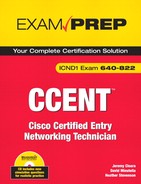
By using the show cdp neighbors detail command or the show cdp entry * command, you can gain even more information about your neighbor Cisco devices. Specifically, you can see all the information from the show cdp neighbors output in addition to the Layer 3 information and the IOS version of your directly connected neighbors. Figure 8.1 illustrates the detailed output of these commands.
Based upon this information, you can already begin to see the topology layout of these three devices, as illustrated in Figure 8.2.
At this point, I am sure you are completely in awe of the wonders that CDP can bring to your administrative duties; however, there are times you may wish to disable CDP. As mentioned before, CDP is a Cisco proprietary protocol enabled by default on all Cisco devices. So what happens when you are not connected to a Cisco device? Although the bandwidth usage is minimal, it still serves no purpose to continue sending CDP advertisements to non-Cisco devices that cannot interpret this protocol. In addition, it is a good idea to disable CDP for security reasons because you can gain so much useful information that could prove fatal in the wrong hands.
You can disable CDP in one of two ways: globally on the Cisco device or on an interface-by-interface basis. To disable CDP for the entire device, you have to configure the no cdp run command in Global Configuration. Otherwise, you can specify on which interfaces to disable CDP advertisement by navigating to those specific interfaces and using the no cdp enable command in the interface configuration.
Verify device configuration and network connectivity using ping, traceroute, telnet, SSH, or other utilities
Telnet is widely used as an in-band management protocol today for remotely administering Cisco devices. As long as you have IP connectivity to the Cisco device and have configured a password on the vty lines, you can remotely administer your Cisco switches and routers.
In User EXEC and Privilege EXEC of the IOS, it is possible to Telnet from your Cisco device to another device. By typing telnet followed by the IP address that you are trying to reach, you initiate a Telnet session from your local router or switch. In all actuality, you do not even need to use the telnet keyword. If you just type an IP address or a hostname (assuming name resolution), the IOS automatically assumes you are attempting to Telnet to that host.
For example, if you Telnet from the 28111 router to the remote 1801, the output would look similar to the following:
CCNA2811>telnet 192.168.100.5
Trying 192.168.100.5 ... Open
User Access Verification
Password:
Engineering1801>
At this point, you can configure the Engineering1801 router as if you were directly consoled into it. However, there may be a time where you need to jump back to your original router to incorporate additional configurations, verify connectivity, or Telnet into other devices. While connected to the remote device, you can suspend your Telnet session temporarily and return to the origin of the Telnet session (CCNA2811 in our example). The useful, but strangely awkward keystroke to suspend a Telnet session in Ctrl+Shift+6 followed by hitting the x key. Keep in mind that this only suspends the Telnet session; the session is still connected and running in a background process.
Exam Alert
Know that the keystroke combination Ctrl+Shift+6, x suspends a Telnet session.
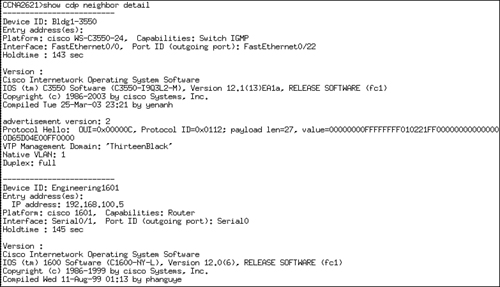
As shown in Figure 8.3, you can verify the Telnet sessions that have originated from the local device by using the show sessions command. This example initiates and suspends two separate Telnet sessions from the CCNA2811 router.
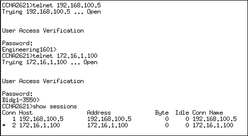
Notice that each session connection is numbered and there is an asterisk next to connection 2. This is the last Telnet session that was suspended and it is the session that will be resumed if you hit the Enter key without typing a command. You can also choose which Telnet session to resume by typing resume, followed by the connection number.
Ctrl+Shift+6, x suspends the Telnet session, but how do you actually close the Telnet session when you are finished? The answer is twofold. You can close a Telnet session from the originating local device by typing the keyword disconnect followed by the connection number. From the device into which you are Telnetted, you can also type exit or logout from User EXEC or Privileged EXEC.
By default, your Cisco devices send their notification messages such as debug outputs, interface alerts, and system error messages to the console port. This means that you cannot see these notifications over a Telnet session to another device by default.
To have these messages copied to the vty lines, you need to use the terminal monitor command in Privileged EXEC mode of the device to which you are telnetted. For instance, in the configuration shown, Router A Telnets into Router B and enters Privileged EXEC mode to type the terminal monitor command. debug outputs, notifications, and errors messages are then sent over the vty lines to be viewed by the remote terminal.
RouterA>telnet 10.1.1.1
Trying 10.1.1.1 ... Open
User Access Verification
Password:
RouterB>enable
Password:
Router#terminal monitor
Objectives:
Configure, verify, and troubleshoot DHCP and DNS operation on a router (including: CLI/SDM)
Implement static and dynamic addressing services for hosts in a LAN environment
One of Cisco’s many goals is to make their routers more versatile than simply just routing packets. Case in point, Cisco has incorporated security, switching, wireless, and/or voice in their line of Integrated Service Routers to provide multi-functionality out of a single device. In that same vein, the Cisco IOS has some convenient features that can provide services to small-to-medium size businesses minimizing the reliance on other devices and servers. One of those services that the Cisco router can provide is to act as DHCP server for a LAN to assign DHCP-enabled devices an IP address, address of the default gateway, domain name, and the DNS server address.
To start the configuration for this service, you have to configure your ethernet interface and make sure that it is up, administratively enabled, and an assigned an IP address as described in this chapter. This makes logical sense since this is the interface that is connected to the DHCP-enabled clients. The next step is to logically define the DHCP address pool using the ip dhcp pool poolname command. Once you enter this command, the router prompt will indicate that you have entered a DHCP sub-configuration mode that looks like the following:
CCNA2811(config)#ip dhcp pool examprep
CCNA2811(dhcp-config)#
Exam Alert
Make sure the interface is enabled and has an IP address assigned for DHCP to work properly.
Once in dhcp-config, you can specify the parameters that will be passed to the requesting clients. For instance, to define the IP network scope that the router will use when leasing IPs, you use the network command followed by the subnet (not single IP) and the subnet mask in decimal form:
CCNA2811(dhcp-config)#network 172.16.0.0 255.255.0.0You can also use CIDR notation for the subnet mask as demonstrated here:
CCNA2811(dhcp-config)#network 172.16.0.0 /16Now, when devices with DCHP enabled come online and send a DHCP request for an IP, the Cisco router will receive that information and respond with an IP from the 172.16.0.0 network. In addition it can also be configured to assign the default gateway (which is probably the router), the address of the DNS server, the domain name of the LAN, and specify the length of time the IP is leased by the client. The configurations for these parameters are as follows:
CCNA2811(dhcp-config)#default-router 172.16.100.1
CCNA2811(dhcp-config)#dns-server 172.16.100.50
CCNA2811(dhcp-config)#domain-name examprep.com
CCNA2811(dhcp-config)#lease 7 2 45
CCNA2811(dhcp-config)#exit
Given the preceding configuration, DHCP-enabled clients will be assigned to the examprep.com domain and have a default gateway of 172.16.100.1, use 172.16.100.50 as a DNS server to resolve domain names to IP, and DHCP lease of this information will last for 7 days, 2 hours, and 45 minutes.
Since we already statically assigned the IP address of 172.16.100.1 to our default gateway and 172.16.100.50 to our DNS server, we want to make sure the router does not assign these IP addresses to device or else it would cause an IP conflict in our network. To exclude an IP address or an IP address range, use the ip dhcp excluded-address ip-address in Global Configuration for a single IP or define a range of IPs using the same command but defining a start IP and end IP.
In our example, we want to exclude the IP’s 172.16.100.1 and 172.16.100.50, so our configuration would look like:
CCNA2811(config)#ip dhcp excluded-address 172.16.100.1
CCNA2811(config)#ip dhcp excluded-address 172.16.100.50
If we used that 172.16.100.x range for other statically assigned devices, we could simply just exclude all IP addresses from 172.16.100.1 through 172.16.100.254 like this:
CCNA2811(config)#ip dhcp excluded-address 172.16.100.1 172.16.100.254To verify what devices are assigned IP’s from our router’s address scope, use the show ip dhcp binding command:
CCNA2811#show ip dhcp binding
Bindings from all pools not associated with VRF:
IP address       Client-ID/            Lease expiration      Type
                 Hardware address/
                 User name
172.16.100.2     01e0.041f.a632.a2     Dec 27 2007 11:59 PM  Automatic
Caution
DHCP Can Cause Router Amnesia When I say router amnesia, I am referring to the loss of memory that can occur when you enable DHCP, especially in larger networks. Since this service requires maintaining all the IP leases it administers, it is possible to consume all of your router’s memory resources if your network is too large and you have a lengthy lease time. In other words, use this service sparingly if your network fits the small-to-medium sized mold. In addition, if you have not done so already, upgrade the router’s memory to whatever level or whatever budget you can afford to help unburden some of the information it will need to retain when DHCP is enabled.
Some of you may be reading this DHCP functionality and realize that you do not need it because you already have a configured and fully functional DHCP server. The Cisco IOS also give you the option to configure your router’s interfaces to be a DHCP client as well; allowing you to use your existing DHCP server and have it assign an IP address to your interface. The command to do this is similar to statically assigning an IP address to your interface, except you specify the keyword dhcp instead of an actual IP address:
CCNA2811(config)# interface FastEthernet 0/0
CCNA2811(config-if)# ip address dhcp
The address that is assigned to the router’s interface cannot be seen by using the show running-config command since it is a temporary address. Instead, you can verify it by using the show dhcp lease command:
CCNA2811#show dhcp lease
Temp IP addr: 172.16.100.2 for peer on Interface: FastEthernet0
Temp  sub net mask: 255.255.0.0
   DHCP Lease server: 172.16.1.1, state: 3 Bound
   DHCP transaction id: 1967
   Lease: 16000 secs,  Renewal: 3000 secs,  Rebind: 16000 secs
Temp default-gateway addr: 172.16.1.1
   Next timer fires after: 00:00:32
   Retry count: 0   Client-ID: cisco-0019.e86a.6fc0-Vl1
Hostname: CCNA2811This chapter dealt with a plethora of commands and their respective syntaxes and outputs. In Global Configuration, you learned how to manipulate the startup process using either the config-register or boot system commands. Additionally, you saw how to use the hostname command to name your router or switch and how to create a message-of-the-day login banner with the banner motd command. To secure Privileged EXEC, you saw that the enable password command displays the password in clear text; however, the enable secret command encrypts the password using a one-way MD5 hash and overrides the enable password command if both are configured. For DNS-specific functions, you discovered that you can create static DNS entries with the ip host command or specify DNS servers using the ip name-server command.
In the line configuration for console, Telnet, and the aux port, you saw that you can configure a layer of security by having administrators enter a password to get into User EXEC. This was achieved by using the login and the password combo in the line configuration of each EXEC line. Additionally, you saw the utility of the exec-timeout command for changing the default timeout for an inactive EXEC session. Because these passwords are all in clear text, you can encrypt them in Global Configuration, using the service password-encryption command.
The configuration of interfaces entails assigning an IP address to a physical interface in a using the ip address command followed by the IP address and subnet mask or the keyword dhcp for dynamically assigned IP’s by a DHCP server. One final imperative interface configuration step entails using the no shutdown command to administratively enable the interface.
You know from this chapter that the copy command can be used to meet several objectives such as saving the configuration, backing up and upgrading your IOS from a TFTP server, and backing up and restoring your configurations. You learned that the syntax of the copy command is copy from a source to a destination. The keywords you can use to identify the source and destination are startup-config, running-config, tftp, and flash.
To see your configurations, you now know that the show running-config command can show you the active configuration in RAM, and that show startup-config displays the configuration booted from NVRAM that you saved with the copy running-config startup-config command. For verification and viewing statistics of interfaces, you discovered that the show interfaces or the show ip interface brief command show you that the interface statues can be one of the following: up/line protocol up (active), up/line protocol down (Layer 2 down), down/line protocol down (Layer 1 down), administratively down/line protocol down (interface requires no shutdown command). What’s more, the show controller serial command can show you whether the interface has the DTE or the DCE cable connected to it in a lab environment with a cross-over serial cable.
You can sleep better at night knowing now that your Cisco devices, by default, receive Layer 2 proprietary CDP multicast messages from directly connected Cisco devices that advertise the hostname, local and remote interfaces, capabilities, device model, and its hold-down time.
You saw these statistics by using the show cdp neighbors command; however, you also saw the IOS revision and the Layer 3 address of your neighbors by using the show cdp neighbors detail or show cdp entry * command. Disabling this useful utility was demonstrated with the no cdp run command in Global Configuration or no cdp enable in the interface configuration.
In this chapter, you also learned that you can Telnet into other devices from your Cisco router or switch. You suspended the Telnet session by using the Ctrl+Shift+6, x keystroke and verified that Telnet session by typing show sessions. Closing the Telnet session was achieved by typing exit or logout while in the active Telnet session, or disconnect followed by the connection number in the device where the Telnet originated.
Finally, we saw how Cisco routers have expanded their functionality beyond routing packets to include providing DHCP services for small-to-medium sized LANs. When DHCP-enabled clients send a DHCP request to the router, it responds with an IP address from its configured scope of IPs. In addition, the router can provide the address of the DNS server, default gateway, and the domain name of the LAN. To configure these parameters, you have to define the logical DHCP pool using the ip dhcp pool pool_name command, which will take you into a dhcp-config mode where you define the network and other parameters that will be passed to the clients.
ip domain-lookup
You are now onsite at the customer’s location and it is time to prove your configuration skills by setting up their router with the following parameters. This exercise assumes you have a router that is not in production to utilize.
Estimated Time: 25 minutes
In Global Configuration, assign the hostname, CstmrARtr, create an appropriate login banner, and use the strongest encryption for access to Privileged EXEC with the password, giforgot.
In line configuration, secure Telnet and console access by using the password imnotsure.
For the LAN interface, assign the IP address of 172.16.31.17 /28 and enable the interface.
For the serial interface, assign the IP address of 192.168.1.17 /30 and enable the interface.
Verify the status of your interfaces by using the
show interfacesandshow ip int brief.Verify your active configuration and save it to NVRAM.
That configuration should look similar to the following 2811 configuration:
Current configuration:
!
version 12.3
service timestamps debug uptime
service timestamps log uptime
no service password-encryption
!
hostname CstmrARtr
!
enable secret 5 $1$PHvQ$Gouu3MIDqY9G5d9hq9tr7/
!
boot-start-marker
boot-end-marker
!
memory-size iomem 15
no aaa new-model
ip subnet-zero
!
!
ip cef
!
!
interface FastEthernet0
 description /28 is 255.255.255.240 in decimal notation
 ip address 172.16.31.17 255.255.255.240
 no ip directed-broadcast
!
interface FastEthernet1
 no ip address
 no ip directed-broadcast
 shutdown
!
interface Serial0/0
 description /30 is 255.255.255.252 in decimal notation
 ip address 192.168.1.17 255.255.255.252
 no ip directed-broadcast
 no fair-queue
!
ip classless
!
banner motd ^C This is a private system and may be accessed only by authorized users.
? Unauthorized access is strictly prohibited and will be enforced to the full
? extent of the law.^C
!
line con 0
 exec-timeout 0 0
 password imnotsure
 login
 transport input none
line vty 0 4
 password imnotsure
 login
!
end
The password configurations on the terminal lines serve as a way to protect your router or switch from anyone gaining access to User EXEC. | |
The | |
CDP enables Cisco administrators to gain information from directly connected Cisco devices without requiring that they be connected with a terminal session. The | |
| |
Given the |
D. To assign a login prompt and password for only the first vty line, you have to navigate to line vty 0. Answer A is incorrect because | |
C. The first part of the | |
A, B. The | |
C. The configuration was saved to Notepad through the use of the | |
A. | |
B. If the | |
C. Ctrl+Shift+6, x suspends the Telnet session. Answers A, B, and D are incorrect because those commands will actually disconnect the Telnet session. | |
D. Because the interface configuration is configured in a shutdown state, the interface status should report the fast ethernet interface as administratively down/line protocol is down. Answers A, B, and C are incorrect because a shutdown interface does not have the Physical layer or the Data Link layer in an up state. | |
A, D. Because there is an excessive number of late collisions in the output, it is safe to assume that there is a duplex mismatch. Also, the link is 92% congested as indicated by the load statements (235/255). B is incorrect because the interface status is up/line protocol is up. C is incorrect because the bandwidth is accurate for a FastEthernet interface. | |
B, D. You can resume the suspended Telnet sessions in this device by hitting the Enter key or typing the keyword, | |
B. If connecting directly to a TFTP server from a router, you must use a cross-over cable. Answers A, C, and D are necessary steps to copy files to and from a TFTP server. | |
E. With a /29 or 255.255.255.248 subnet, the increment of these subnets is 8. Starting with 0, counting 10 networks gives you a Network/Subnet identifier of 192.168.100.72 (0,8,16,24,32,40,48,56,64,72). The last IP address in that subnet is 192.168.100.78. Answer A is a network ID and the wrong subnet mask. Answer B is the broadcast address for that subnet. Answer C is that last IP address in ninth subnet with the wrong subnet mask. D is the first valid IP address in that subnet. | |
C. The command to upload your IOS from a TFTP server is |
Odom, Wendell. CCENT/CCNA ICND1 Official Exam Certification Guide (CCENT Exam 640-822 and CCNA Exam 640-802), 2nd Edition, Cisco Press Publishing, 2007.
Boney, James. Cisco IOS in a Nutshell, O’Reilly Publishing, 2001.
“Configuration Fundamentals Command Reference,” www.cisco.com.