Chapter 1 Physical Topology
This book focuses on the commands and methodologies necessary to deploy technologies in a Cisco Routing and Switching environment. This means that if you want to follow along on a task-by-task basis, you will need a lab environment that supports the commands and verification mechanisms this book provides. I consider this an invaluable part of the learning process. All procedural tasks in this book are performed against a specific arrangement of equipment. This chapter illustrates exactly how this equipment will be connected (using both Ethernet and serial interconnections) so that you can create your own training environment.
It should be noted that the CCIE Lab Exam employs two variations of Cisco IOS. Those two versions are relative to routers and switches. In the actual lab, the routers run the 15.3T Universal Software release; this version can be supported on the ISR 2900 Series routers. If you have the ability to acquire access to physical devices, this version of the IOS will support all possible technologies and features that can be seen in the lab. Additionally, the switching environment runs IOS 15.0SE Universal (IP Services). This is supported on the Catalyst 3560X Series switches. It is understood and expected that the majority of readers will not have access to these physical devices. If this is the case for you, it is suggested that you do as much as possible via emulation/virtualization (which may or may not support the IOS versions just listed) using the tools mentioned in this chapter. This leaves you with just a small subset of protocols and features that require rack rental or access to physical equipment.
Physical Layout of Switching Devices
In keeping with how most networks are designed, we will turn our attention to the Layer 2 switching environment we will use to perform all labs found in this book. We begin with a specific arrangement of four Cisco switches. The switches used in this book have Fast Ethernet ports, although switches with Gigabit Ethernet ports can also be used. If you use switches with Gigabit Ethernet ports, you have to keep in mind that when the book asks you to configure interface fastethernet0/1, you will have to configure interface gigabitethernet0/1 instead. These switches will be connected by a series of Ethernet connections, as illustrated in Figure 1-1.
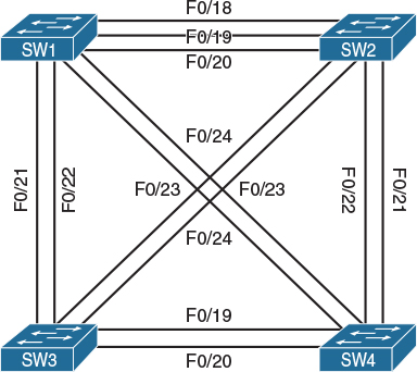
Figure 1-1 Physical Topology—Switches
This arrangement of devices provides a full mesh of redundant connects that support both basic and advanced switching features such as trunks and Ether-channels, while simultaneously providing serviceable links that can be employed to create a wide range of logical topologies. We explore logical topologies verses physical topologies in Chapter 2, “Physical and Logical Topologies.”
Whereas Figure 1-1 outlines the core switching infrastructure used in this book, Figure 1-2 illustrates how the routing—or Layer 3 components—will be connected to this Layer 2 core.

As you can see in Figure 1-2, we have 10 routers that will be physically connected via Ethernet cables to each of the four switches illustrated in Figure 1-1. All routers will be connected to Switch-1 via their FastEthernet0/0 interfaces. However, to facilitate the creation of more diverse Layer 3 topologies, the FastEthernet0/1 interfaces of each router will connect to different switches. Figure 1-2 illustrates how these connections are dispersed between the remaining physical switches.
Serial Interconnections Between Routers
Serial interfaces are slow by comparison to the various types of Ethernet connections available. As a direct result of this, many organizations are moving away from them. However, many technologies and features specific to serial interconnections are still part of the CCIE Routing and Switching blueprint. In order for you to see and experiment with these technologies, I have specified that several groups of routers be linked by individual connections and some multiple connections. Table 1-1 illustrates what devices share these connections and how many.


Lab Options
It is important to note that this book was written using a rack of actual Cisco switches and routers; however, I recognize that many readers might not have access to this type of lab environment. Therefore, this book contains labs that can be run on many different software emulators. Whether you opt to use live equipment, Cisco Virtual Internet Routing Lab (VIRL), or some other emulation package, my intent is to provide you with as much directed hands-on experience as possible. Whereas actual hardware supports every lab included in this book, many emulators do not support features such as serial connections. In these situations, I suggest that you leverage an emulator (such as VIRL) to practice as many labs as possible, and then it may be necessary to get access to live equipment. Another suggestion would be to use Cisco’s Lab Builder offering, which will support all the labs included in this book.
Summary
Hands-on experience working with technologies is the best way to learn and to demonstrate your learning. I cannot emphasis enough how important practical exercises, like those included in this book, will be to your success. So whether you have a lab of real equipment or use an emulator platform, I suggest you practice these labs many times. This will help you learn new things as well as help you retain what you learn longer as you progress through your studies.