Chapter 13 IPSec VPN
VPN tunnels are used to connect physically isolated networks that are more often than not separated by nonsecure internetworks. To protect these connections, we employ the IP Security (IPSec) protocol to make secure the transmission of data, voice, and video between sites. These secure tunnels over the Internet public network are encrypted using a number of advanced algorithms to provide confidentiality of data that is transmitted between multiple sites. This chapter explores how to configure routers to create a permanent secure site-to-site VPN tunnel.
Encryption will be provided by IPSec in concert with VPN tunnels. The Internet Security Association and Key Management Protocol (ISAKMP) and IPSec are essential to building and encrypting VPN tunnels. ISAKMP, also called IKE (Internet Key Exchange), is the negotiation protocol that allows hosts to agree on how to build an IPSec security association.
ISAKMP negotiation consists of two phases:
![]() Phase 1 creates the first tunnel, which protects later ISAKMP negotiation messages.
Phase 1 creates the first tunnel, which protects later ISAKMP negotiation messages.
![]() Phase 2 creates the tunnel that protects data.
Phase 2 creates the tunnel that protects data.
IPSec then encrypts exchanged data by employing encryption algorithms that result in authentication, encryption, and critical anti-replay services.
Lab 13-1: Basic Site-to-Site IPSec VPN
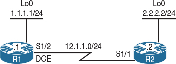
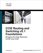
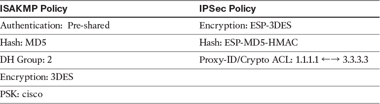
Figure 13-1 Configuring Basic Site-to-Site IPSec VPN (Main Mode)
Figure 13-1 illustrates the topology that will be used in the following lab.
Task 1
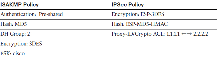
Configure a basic site-to-site IPSec VPN to protect traffic between IP addresses 1.1.1.1 and 2.2.2.2 using the policy shown in Table 13-1.
Table 13-1 Policy Guidelines for Configuring Task 1
Reachability to the loopback0 interfaces is provided in the initial configuration.
ISAKMP, originally defined in RFC 7296, covers the following:
![]() Procedures to authenticate a communicating peer
Procedures to authenticate a communicating peer
![]() How to create and manage security associations (SAs)
How to create and manage security associations (SAs)
![]() Key-generation techniques
Key-generation techniques
![]() Threat mitigation, such as denial-of-service (DoS) and replay attacks
Threat mitigation, such as denial-of-service (DoS) and replay attacks
IKE does not specify any details of key management or key exchange, and it’s not bound to any key-generation techniques. Inside IKE, Cisco uses OAKLEY for the key exchange protocol.
OAKLEY enables you to choose between different well-known Diffie-Hellman (DH) groups. RFC 2412 describes the OAKLEY protocol and covers DH groups 1 through 5. Of these groups, Cisco supports DH groups 1, 2, and 5. RFC 3526 describes DH group 5 and groups 14 through 18. Cisco supports DH groups 5, 14, 15, and 16. RFC 5114 covers DH groups 19 through 26. Of these DH groups, Cisco supports 19, 20, 21, and 24. The following is a list of the DH groups supported by Cisco:
![]() 1: Diffie-Hellman group 1 (768 bit)
1: Diffie-Hellman group 1 (768 bit)
![]() 2: Diffie-Hellman group 2 (1024 bit)
2: Diffie-Hellman group 2 (1024 bit)
![]() 5: Diffie-Hellman group 5 (1536 bit)
5: Diffie-Hellman group 5 (1536 bit)
![]() 14: Diffie-Hellman group 14 (2048 bit)
14: Diffie-Hellman group 14 (2048 bit)
![]() 15: Diffie-Hellman group 15 (3072 bit)
15: Diffie-Hellman group 15 (3072 bit)
![]() 16: Diffie-Hellman group 16 (4096 bit)
16: Diffie-Hellman group 16 (4096 bit)
![]() 19: Diffie-Hellman group 19 (256-bit ECP)
19: Diffie-Hellman group 19 (256-bit ECP)
![]() 20: Diffie-Hellman group 20 (384-bit ECP)
20: Diffie-Hellman group 20 (384-bit ECP)
![]() 21: Diffie-Hellman group 21 (521-bit ECP)
21: Diffie-Hellman group 21 (521-bit ECP)
![]() 24: Diffie-Hellman group 24 (2048 bit, 256-bit subgroup)
24: Diffie-Hellman group 24 (2048 bit, 256-bit subgroup)
ISAKMP and OAKLEY create an authenticated, secure tunnel between two entities, and then negotiate the SA for IPSec. Both peers must authenticate each other and establish a shared key.
Three authentication methods are available: RSA signatures (PKI), RSA encrypted pseudorandom numbers (nonces), and preshared keys (PSK). The DH protocol is used to agree on a common session key.
IPSec uses a different shared key from ISAKMP and OAKLEY. The IPSec shared key can be derived by using DH again to ensure Perfect Forward Secrecy (PFS) or by refreshing the shared secret derived from the original DH exchange.
IKE is a hybrid protocol that establishes a shared security policy and authenticated keys for services that require keys, such as IPSec. Before an IPSec tunnel is established, each device must be able to identify its peer. ISAKMP and IKE are both used interchangeably; however, these two items are somewhat different. IKE was originally defined by RFC 2409. IKE version 2 is currently described by RFC 7296.
IKE Phase 1: The two ISAKMP peers establish a secure and an authenticated channel. This channel is known as the ISAKMP SA. There are two modes defined by ISAKMP: Main Mode and Aggressive Mode.
IKE Phase 2: SAs are negotiated on behalf of services such as IPSec that need keying material. This phase is called Quick Mode.
To configure IKE Phase 1, you need to configure ISAKMP policies. It is possible to configure multiple policies with different configuration statements and then let the two hosts negotiate the policies. The first matched policy on the responder will be used.
Let’s start configuring Phase 1 on both routers:
On R1:
R1(config)# crypto isakmp policy 10
R1(config-isakmp)# hash md5
R1(config-isakmp)# authentication pre-share
R1(config-isakmp)# group 2
R1(config-isakmp)# encryption 3des
R1(config-isakmp)# exit
The IP address of a loopback interface can be used when there are multiple paths to reach the peer’s IP address:
R1(config)# crypto isakmp key cisco address 12.1.1.2
On R2:
R2(config)# crypto isakmp policy 10
R2(config-isakmp)# hash md5
R2(config-isakmp)# authentication pre-share
R2(config-isakmp)# group 2
R2(config-isakmp)# encryption 3des
R2(config-isakmp)# exit
R2(config)# crypto isakmp key cisco address 12.1.1.1
To configure the Phase 2, we need to define the transform-set, which specifies the hashing, the security protocol, and the encryption used for Phase 2:
On Both Routers:
Rx(config)# crypto ipsec transform-set TSET esp-3des esp-md5-hmac
Rx(cfg-config-trans)# exit
Next, we need to define the crypto ACL/proxy ID, which defines the interesting traffic:
On R1:
R1(config)# access-list 100 permit ip host 1.1.1.1 host 2.2.2.2
On R2:
R2(config)# access-list 100 permit ip host 2.2.2.2 host 1.1.1.1
In the last step, a crypto map is configured to specify the peer, crypto ACL, and the transform set. There are three choices when configuring the following crypto map:
![]() IPSec-ISAKMP: This is the best option. It states that we are using ISAKMP to encrypt and decrypt the key.
IPSec-ISAKMP: This is the best option. It states that we are using ISAKMP to encrypt and decrypt the key.
![]() IPSec-manual: This is the worst choice. It means that the key needs to be entered manually. (Can you imagine entering a 512-bit key manually?)
IPSec-manual: This is the worst choice. It means that the key needs to be entered manually. (Can you imagine entering a 512-bit key manually?)
![]() GDOI: This choice is used for GETVPN configuration. It stands for group domain of interpretation.
GDOI: This choice is used for GETVPN configuration. It stands for group domain of interpretation.
On R1:
R1(config)# crypto map TST 10 ipsec-isakmp
You should see the following console message:
% NOTE: This new crypto map will remain disabled until a peer
and a valid access list have been configured.
R1(config-crypto-map)# set peer 12.1.1.2
R1(config-crypto-map)# match address 100
R1(config-crypto-map)# set transform-set TSET
R1(config-crypto-map)# exit
On R2:
R2(config)# crypto map TST 10 ipsec-isakmp
R2(config-crypto-map)# set peer 12.1.1.1
R2(config-crypto-map)# match address 100
R2(config-crypto-map)# set transform-set TSET
R2(config-crypto-map)# exit
The final step applies the crypto map to the interface facing the other peer:
On R1:
R1(config)# interface Serial 1/2
R1(config-if)# crypto map TST
You should see the following console message:
%CRYPTO-6-ISAKMP_ON_OFF: ISAKMP is ON
On R2:
R2(config)# interface Serial 1/1
R2(config-if)# crypto map TST
Let’s verify the configuration before testing:
On R1:
R1# show crypto isakmp policy
Global IKE policy
Protection suite of priority 10
encryption algorithm: Three key triple DES
hash algorithm: Message Digest 5
authentication method: Pre-Shared Key
Diffie-Hellman group: # 2 (1024 bit)
lifetime: 86400 seconds, no volume limit
R1# show crypto isakmp key
Keyring Hostname/Address Preshared Key
default 12.1.1.2 cisco
Now we can test the configuration:
On R1:
R1# debug crypto isakmp
Crypto ISAKMP debugging is on
R1# debug crypto ipsec
Crypto IPSEC debugging is on
R1# ping 2.2.2.2 source loopback0
Type escape sequence to abort.
Sending 5, 100-byte ICMP Echos to 2.2.2.2, timeout is 2 seconds:
Packet sent with a source address of 1.1.1.1
The first ICMP packet triggers the ISAKMP process, as this is our interesting traffic matching the configured crypto ACL.
Before we actually start sending IKE packets to the peer, the router first checks whether there is a local SA (security association) matching that traffic. This check is against the IPSec SA and not an IKE SA.
We can see the outbound and remote IP addresses, port number, local proxy, and remote proxy. The protocol used is ESP, and the transform-set is the default mode of tunnel.
IPSEC(sa_request): ,
(key eng. msg.) OUTBOUND local= 12.1.1.1:500, remote= 12.1.1.2:500,
local_proxy= 1.1.1.1/255.255.255.255/0/0 (type=1),
remote_proxy= 2.2.2.2/255.255.255.255/0/0 (type=1),
protocol= ESP, transform= esp-3des esp-md5-hmac (Tunnel),
lifedur= 3600s and 4608000kb,
spi= 0x0(0), conn_id= 0, keysize= 0, flags= 0x0
The following highlighted line specifies that no SA was found. The router first tried to find an IPSec SA matching the outgoing connection, but it failed to find one.
ISAKMP:(0): SA request profile is (NULL)
ISAKMP: Created a peer struct for 12.1.1.2, peer port 500
ISAKMP: New peer created peer = 0x4B24E100 peer_handle = 0x80000003
ISAKMP: Locking peer struct 0x4B24E100, refcount 1 for isakmp_initiator
ISAKMP: local port 500, remote port 500
ISAKMP: set new node 0 to QM_IDLE
ISAKMP: Find a dup sa in the avl tree during calling isadb_insert sa = 4B331BEC
IKE Phase 1 (Main Mode) Message 1
By default, IKE Main Mode is used, so we should expect six packets for Phase 1. The following highlighted message states that the Aggressive Mode cannot start. However, this does not mean that we are experiencing errors; it just means that Aggressive Mode is not configured on the local router.
ISAKMP:(0):Can not start Aggressive mode, trying Main mode.
The router checks for the configured ISAKMP policy and sees that pre-shared key (PSK) authentication is configured. It has to check whether there is a key for the configured peer as well. After that, the first IKE packet is sent out to the peer’s IP address on port UDP 500.
The packet contains locally configured ISAKMP policies to be negotiated by the peer. The pre-shared key for the remote peer is found, which means that ISAKMP is going to use it to authenticate the peer. This will happen in the last stage of IKE Phase 1.
ISAKMP:(0):found peer pre-shared key matching 12.1.1.2
ISAKMP:(0): constructed NAT-T vendor-rfc3947 ID
ISAKMP:(0): constructed NAT-T vendor-07 ID
ISAKMP:(0): constructed NAT-T vendor-03 ID
ISAKMP:(0): constructed NAT-T vendor-02 ID
ISAKMP:(0):Input = IKE_MESG_FROM_IPSEC, IKE_SA_REQ_MM
ISAKMP:(0):Old State = IKE_READY New State = IKE_I_MM1
ISAKMP:(0): beginning Main Mode exchange
ISAKMP:(0): sending packet to 12.1.1.2 my_port 500 peer_port 500 (I) MM_NO_STATE
The router initiating the IKE exchange is called the initiator, and the router responding to IKE request is called the responder. The initiator (R1) has sent the ISAKMP policy along with vendor-specific IDs that are part of the IKE packet payload. MM_NO_STATE indicates that ISAKMP SA has been created, but nothing else has happened yet.
IKE Phase 1 (Main Mode) Message 2
It looks like everything is going smoothly. We received a response packet from the peer. However, this is one area where things can typically go wrong.
The received packet contains the SA chosen by the peer and some other useful information, such as vendor IDs. Those vendor-specific payloads are used to discover network address translation (NAT) along the path and to maintain keepalives. The router matches the ISAKMP policy from the packet to one that’s locally configured. If there is a match, the tunnel-establishment process continues. If the policy configured on both routers is not the same, the crosscheck process fails and the tunnel is down.
ISAKMP:(0):Sending an IKE IPv4 Packet.
ISAKMP (0): received packet from 12.1.1.2 dport 500 sport 500 Global (I) MM_NO_STATE
ISAKMP:(0):Input = IKE_MESG_FROM_PEER, IKE_MM_EXCH
ISAKMP:(0):Old State = IKE_I_MM1 New State = IKE_I_MM2
ISAKMP:(0): processing SA payload. message ID = 0
ISAKMP:(0): processing vendor id payload
ISAKMP:(0): vendor ID seems Unity/DPD but major 69 mismatch
ISAKMP (0): vendor ID is NAT-T RFC 3947
ISAKMP:(0):found peer pre-shared key matching 12.1.1.2
ISAKMP:(0): local preshared key found
ISAKMP : Scanning profiles for xauth ...
IS.!!!!
Success rate is 80 percent (4/5), round-trip min/avg/max = 44/45/48 ms
The router is processing ISAKMP parameters that have been sent as the reply. The vendor IDs are processed to determine whether the peer supports the NAT-Traversal, Dead Peer Detection feature. ISAKMP policy is checked against policies defined locally. The atts are acceptable message indicates that the ISAKMP policy matches with remote peer:
R1# AKMP:(0):Checking ISAKMP transform 1 against priority 10 policy
ISAKMP: encryption 3DES-CBC
ISAKMP: hash MD5
ISAKMP: default group 2
ISAKMP: auth pre-share
ISAKMP: life type in seconds
ISAKMP: life duration (VPI) of 0x0 0x1 0x51 0x80
ISAKMP:(0):atts are acceptable. Next payload is 0
The lifetime timer has been started. Note that default value is used (86,400 seconds). This is the lifetime for ISAKMP SA. Note that IPSec SAs have their own lifetime parameters, which may be defined as number of seconds or kilobytes of transmitted traffic.
ISAKMP:(0):Acceptable atts:actual life: 0
ISAKMP:(0):Acceptable atts:life: 0
ISAKMP:(0):Fill atts in sa vpi_length:4
ISAKMP:(0):Fill atts in sa life_in_seconds:86400
ISAKMP:(0):Returning Actual lifetime: 86400
ISAKMP:(0)::Started lifetime timer: 86400.
ISAKMP:(0): processing vendor id payload
ISAKMP:(0): vendor ID seems Unity/DPD but major 69 mismatch
ISAKMP (0): vendor ID is NAT-T RFC 3947
ISAKMP:(0):Input = IKE_MESG_INTERNAL, IKE_PROCESS_MAIN_MODE
ISAKMP:(0):Old State = IKE_I_MM2 New State = IKE_I_MM2
IKE Phase 1 (Main Mode) Message 3
The third message is sent out containing key-exchange (KE) information for the Diffie-Hellman (DH) secure key-exchange process:
ISAKMP:(0): sending packet to 12.1.1.2 my_port 500 peer_port 500 (I) MM_SA_SETUP
ISAKMP:(0):Sending an IKE IPv4 Packet.
ISAKMP:(0):Input = IKE_MESG_INTERNAL, IKE_PROCESS_COMPLETE
ISAKMP:(0):Old State = IKE_I_MM2 New State = IKE_I_MM3
IKE Phase 1 (Main Mode) Message 4
The fourth message has been received from the peer. This message contains the KE payload, and based on that information, both peers can generate a common session key to be used in securing further communication. The pre-shared key configured locally for the peer is used in this calculation.
After receiving this message, peers can determine whether there is NAT along the path.
ISAKMP (0): received packet from 12.1.1.2 dport 500 sport 500 Global (I) MM_SA_SETUP
ISAKMP:(0):Input = IKE_MESG_FROM_PEER, IKE_MM_EXCH
ISAKMP:(0):Old State = IKE_I_MM3 New State = IKE_I_MM4
ISAKMP:(0): processing KE payload. message ID = 0
ISAKMP:(0): processing NONCE payload. message ID = 0
ISAKMP:(0):found peer pre-shared key matching 12.1.1.2
ISAKMP:(1002): processing vendor id payload
ISAKMP:(1002): vendor ID is Unity
ISAKMP:(1002): processing vendor id payload
ISAKMP:(1002): vendor ID is DPD
ISAKMP:(1002): processing vendor id payload
ISAKMP:(1002): speaking to another IOS box!
ISAKMP:received payload type 20
ISAKMP (1002): His hash no match - this node outside NAT
ISAKMP:received payload type 20
ISAKMP (1002): No NAT Found for self or peer
ISAKMP:(1002):Input = IKE_MESG_INTERNAL, IKE_PROCESS_MAIN_MODE
ISAKMP:(1002):Old State = IKE_I_MM4 New State = IKE_I_MM4
IKE Phase 1 (Main Mode) Message 5
The fifth message is used for sending out authentication information to the peer. This information is transmitted under the protection of the common shared secret.
ISAKMP:(1002):Send initial contact
ISAKMP:(1002):SA is doing pre-shared key authentication using id type ID_IPV4_ADDR
ISAKMP (1002): ID payload
next-payload : 8
type : 1
address : 12.1.1.1
protocol : 17
port : 500
length : 12
ISAKMP:(1002):Total payload length: 12
ISAKMP:(1002): sending packet to 12.1.1.2 my_port 500 peer_port 500 (I) MM_KEY_EXCH
MM_KEY_EXCH indicates that the peers have exchanged Diffie-Hellman public keys and have generated a shared secret. The ISAKMP SA remains unauthenticated. Note that the process of authentication has just been started.
ISAKMP:(1002):Sending an IKE IPv4 Packet.
ISAKMP:(1002):Input = IKE_MESG_INTERNAL, IKE_PROCESS_COMPLETE
ISAKMP:(1002):Old State = IKE_I_MM4 New State = IKE_I_MM5
IKE Phase 1 (Main Mode) Message 6
The peer identity is verified by the local router and the SA is established. This message finishes ISAKMP Main Mode (Phase I), and the status is changed to IKE_P1_COMPLETE.
ISAKMP (1002): received packet from 12.1.1.2 dport 500 sport 500 Global (I) MM_KEY_EXCH
ISAKMP:(1002): processing ID payload. message ID = 0
ISAKMP (1002): ID payload
next-payload : 8
type : 1
address : 12.1.1.2
protocol : 17
port : 500
length : 12
ISAKMP:(0):: peer matches *none* of the profiles
ISAKMP:(1002): processing HASH payload. message ID = 0
ISAKMP:(1002):SA authentication status:
authenticated
ISAKMP:(1002):SA has been authenticated with 12.1.1.2
ISAKMP: Trying to insert a peer 12.1.1.1/12.1.1.2/500/, and inserted successfully 4B24E100.
ISAKMP:(1002):Input = IKE_MESG_FROM_PEER, IKE_MM_EXCH
ISAKMP:(1002):Old State = IKE_I_MM5 New State = IKE_I_MM6
ISAKMP:(1002):Input = IKE_MESG_INTERNAL, IKE_PROCESS_MAIN_MODE
ISAKMP:(1002):Old State = IKE_I_MM6 New State = IKE_I_MM6
ISAKMP:(1002):Input = IKE_MESG_INTERNAL, IKE_PROCESS_COMPLETE
ISAKMP:(1002):Old State = IKE_I_MM6 New State = IKE_P1_COMPLETE
IKE Phase 2 (Quick Mode) Message 1
Now it’s time for Phase 2, which is Quick Mode (QM). The router sends out the packet containing local proxy IDs (network/host addresses to be protected by the IPSec tunnel) and the security policy defined by the transform set.
The state of IKE is QM_IDLE. This indicates that the ISAKMP SA is idle. It remains authenticated with its peer and may be used for subsequent Quick Mode exchanges. It is in a quiescent state.
ISAKMP:(1002):beginning Quick Mode exchange, M-ID of 623921701
ISAKMP:(1002):QM Initiator gets spi
ISAKMP:(1002): sending packet to 12.1.1.2 my_port 500 peer_port 500 (I) QM_IDLE
ISAKMP:(1002):Sending an IKE IPv4 Packet.
ISAKMP:(1002):Node 623921701, Input = IKE_MESG_INTERNAL, IKE_INIT_QM
ISAKMP:(1002):Old State = IKE_QM_READY New State = IKE_QM_I_QM1
ISAKMP:(1002):Input = IKE_MESG_INTERNAL, IKE_PHASE1_COMPLETE
ISAKMP:(1002):Old State = IKE_P1_COMPLETE New State = IKE_P1_COMPLETE
ISAKMP (1002): received packet from 12.1.1.2 dport 500 sport 500 Global (I) QM_IDLE
The routers are negotiating the parameters for the IPSec tunnel that will be used for traffic transmission. These parameters are defined by the crypto ipsec transform-set command.
Note that lifetime values of the IPSec SA are visible at this moment. You are able to set this both globally and in the crypto map entry. The attr are acceptable message indicates that the IPSec parameters defined as the IPSec transform-set match on both sides.
ISAKMP:(1002): processing HASH payload. message ID = 623921701
ISAKMP:(1002): processing SA payload. message ID = 623921701
ISAKMP:(1002):Checking IPSec proposal 1
ISAKMP: transform 1, ESP_3DES
ISAKMP: attributes in transform:
ISAKMP: encaps is 1 (Tunnel)
ISAKMP: SA life type in seconds
ISAKMP: SA life duration (basic) of 3600
ISAKMP: SA life type in kilobytes
ISAKMP: SA life duration (VPI) of 0x0 0x46 0x50 0x0
ISAKMP: authenticator is HMAC-MD5
ISAKMP:(1002):atts are acceptable.
IPSEC(validate_proposal_request): proposal part # 1
IPSEC(validate_proposal_request): proposal part # 1,
(key eng. msg.) INBOUND local= 12.1.1.1:0, remote= 12.1.1.2:0,
local_proxy= 1.1.1.1/255.255.255.255/0/0 (type=1),
remote_proxy= 2.2.2.2/255.255.255.255/0/0 (type=1),
protocol= ESP, transform= NONE (Tunnel),
lifedur= 0s and 0kb,
spi= 0x0(0), conn_id= 0, keysize= 0, flags= 0x0
Crypto mapdb : proxy_match
src addr : 1.1.1.1
dst addr : 2.2.2.2
protocol : 0
src port : 0
dst port : 0
ISAKMP:(1002): processing NONCE payload. message ID = 623921701
ISAKMP:(1002): processing ID payload. message ID = 623921701
ISAKMP:(1002): processing ID payload. message ID = 623921701
The local and remote proxies are defined. This indicates the sources and destinations set in crypto ACL, which defines the interesting traffic for the IPSec tunnel. Remember that it is enough when only one entry is mirrored. If not, you may get the following entry in the debug output: PSEC(initialize_sas): invalid proxy IDs.
ISAKMP:(1002): Creating IPSec SAs
inbound SA from 12.1.1.2 to 12.1.1.1 (f/i) 0/ 0
(proxy 2.2.2.2 to 1.1.1.1)
has spi 0x2E5593AE and conn_id 0
lifetime of 3600 seconds
lifetime of 4608000 kilobytes
outbound SA from 12.1.1.1 to 12.1.1.2 (f/i) 0/0
(proxy 1.1.1.1 to 2.2.2.2)
has spi 0x5AEFD96D and conn_id 0
lifetime of 3600 seconds
lifetime of 4608000 kilobytes
The IPSec SAs have been created and inserted into the router’s security associations database (SADB). SAs are distinguished by Security Parameter Index (SPI) values, which are also used to differentiate many tunnels terminated on the same router. Note that two SPI values are generated for one tunnel: one SPI for the inbound SA and one SPI for the outbound SA.
The SPI value is inserted in the ESP header of the packet leaving the router. At the other side of the tunnel, the SPI value inserted into the ESP header enables the router to reach parameters and keys that have been dynamically agreed upon during IKE negotiations, or session key refreshment in case of lifetime timeout.
ISAKMP:(1002): sending packet to 12.1.1.2 my_port 500 peer_port 500 (I) QM_IDLE
ISAKMP:(1002):Sending an IKE IPv4 Packet.
ISAKMP:(1002):deleting node 623921701 error FALSE reason "No Error"
ISAKMP:(1002):Node 623921701, Input = IKE_MESG_FROM_PEER, IKE_QM_EXCH
ISAKMP:(1002):Old State = IKE_QM_I_QM1 New State = IKE_QM_PHASE2_COMPLETE
IPSEC(key_engine): got a queue event with 1 KMI message(s)
Crypto mapdb : proxy_match
src addr : 1.1.1.1
dst addr : 2.2.2.2
protocol : 0
src port : 0
dst port : 0
IPSEC(crypto_ipsec_sa_find_ident_head): reconnecting with the same proxies and peer 12.1.1.2
IPSEC(policy_db_add_ident): src 1.1.1.1, dest 2.2.2.2, dest_port 0
IPSEC(create_sa): sa created,
(sa) sa_dest= 12.1.1.1, sa_proto= 50,
sa_spi= 0x2E5593AE(777360302),
sa_trans= esp-3des esp-md5-hmac , sa_conn_id= 2003
sa_lifetime(k/sec)= (4571378/3600)
IPSEC(create_sa): sa created,
(sa) sa_dest= 12.1.1.2, sa_proto= 50,
sa_spi= 0x5AEFD96D(1525668205),
sa_trans= esp-3des esp-md5-hmac , sa_conn_id= 2004
sa_lifetime(k/sec)= (4571378/3600)
IPSEC(update_current_outbound_sa): get enable SA peer 12.1.1.2 current outbound sa to SPI 5AEFD96D
IPSEC(update_current_outbound_sa): updated peer 12.1.1.2 current outbound sa to SPI 5AEFD96D
ISAKMP:(1001):purging SA., sa=4B23D6D0, delme=4B23D6D0
R1# show crypto isakmp sa
IPv4 Crypto ISAKMP SA
dst src state conn-id status
12.1.1.2 12.1.1.1 QM_IDLE 1002 ACTIVE
IPv6 Crypto ISAKMP SA
R1# show crypto ipsec sa
interface: Serial1/2
Crypto map tag: TST, local addr 12.1.1.1
protected vrf: (none)
local ident (addr/mask/prot/port): (1.1.1.1/255.255.255.255/0/0)
remote ident (addr/mask/prot/port): (2.2.2.2/255.255.255.255/0/0)
current_peer 12.1.1.2 port 500
PERMIT, flags={origin_is_acl,}
# pkts encaps: 4, # pkts encrypt: 4, # pkts digest: 4
# pkts decaps: 4, # pkts decrypt: 4, # pkts verify: 4
# pkts compressed: 0, # pkts decompressed: 0
# pkts not compressed: 0, # pkts compr. failed: 0
# pkts not decompressed: 0, # pkts decompress failed: 0
# send errors 1, # recv errors 0
local crypto endpt.: 12.1.1.1, remote crypto endpt.: 12.1.1.2
path mtu 1500, ip mtu 1500, ip mtu idb Serial1/2
current outbound spi: 0xE53B1D2(240366034)
PFS (Y/N): N, DH group: none
inbound esp sas:
spi: 0xBDAF9A28(3182402088)
transform: esp-3des esp-md5-hmac ,
in use settings ={Tunnel, }
conn id: 2005, flow_id: NETGX:5, sibling_flags 80000046, crypto map: TST
sa timing: remaining key lifetime (k/sec): (4405715/2686)
IV size: 8 bytes
replay detection support: Y
Status: ACTIVE
inbound ah sas:
inbound pcp sas:
outbound esp sas:
spi: 0xE53B1D2(240366034)
transform: esp-3des esp-md5-hmac ,
in use settings ={Tunnel, }
conn id: 2006, flow_id: NETGX:6, sibling_flags 80000046, crypto map: TST
sa timing: remaining key lifetime (k/sec): (4405715/2686)
IV size: 8 bytes
replay detection support: Y
Status: ACTIVE
outbound ah sas:
outbound pcp sas:
Task 2
Erase the startup configuration of the routers and reload them before proceeding to the next lab.
Lab 13-2: Basic Site-to-Site IPSec VPN and NAT
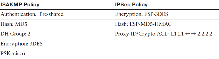
Figure 13-2 Configuring Basic Site-to-Site IPSec VPN and NAT
Figure 13-2 illustrates the topology that will be used in the following lab.
Task 1
Reachability to the loopback interfaces of R1 and R3 should be provided using static routes based on the following policy:
![]() R1 and R3 should be configured with a static default route pointing to R2.
R1 and R3 should be configured with a static default route pointing to R2.
![]() R2 should be configured with two static routes: one for network 1.1.1.0/24 through R1, and the second for 3.3.3.0/24 through R3.
R2 should be configured with two static routes: one for network 1.1.1.0/24 through R1, and the second for 3.3.3.0/24 through R3.
On R1:
R1(config)# ip route 0.0.0.0 0.0.0.0 12.1.1.2
On R3:
R3(config)# ip route 0.0.0.0 0.0.0.0 23.1.1.2
On R2:
R2(config)# ip route 1.1.1.0 255.255.255.0 12.1.1.1
R2(config)# ip route 3.3.3.0 255.255.255.0 23.1.1.3
Let’s test the configuration:
On R1:
R1# ping 3.3.3.3 source loopback0
Type escape sequence to abort.
Sending 5, 100-byte ICMP Echos to 3.3.3.3, timeout is 2 seconds:
Packet sent with a source address of 1.1.1.1
!!!!!
Success rate is 100 percent (5/5), round-trip min/avg/max = 56/56/60 ms
Task 2
Configure static network address translation (NAT) on R2 so that R1’s S1/2 IP address is seen on R3 as 23.1.1.1:
On R2:
R2(config)# interface Serial1/1
R2(config-if)# ip nat inside
R2(config)# interface Serial1/3
R2(config-if)# ip nat outside
R2(config-if)# exit
R2(config)# ip nat inside source static 12.1.1.1 23.1.1.1
Let’s verify the configuration:
On R2:
R2# show ip nat translations
Pro Inside global Inside local Outside local Outside global
--- 23.1.1.1 12.1.1.1 --- ---
Task 3
Configure a basic site-to-site IPSec VPN to protect traffic between 1.1.1.1 and 3.3.3.3 networks using the policy shown in Table 13-2.
Table 13-2 Policy Guidelines for Configuring Task 3
By now we have a step-by-step process for IPSec configuration that we can use:
Step 1. Configure ISAKMP using pre-shared authentication, MD5 hashing, DH group 2, and a PSK of “cisco” on both R1 and R3:
On R1:
R1(config)# crypto isakmp policy 10
R1(config-isakmp)# hash md5
R1(config-isakmp)# authentication pre-share
R1(config-isakmp)# group 2
R1(config-isakmp)# encryption 3des
R1(config-isakmp)# exit
On R3:
R3(config)# crypto isakmp policy 10
R3(config-isakmp)# hash md5
R3(config-isakmp)# authentication pre-share
R3(config-isakmp)# group 2
R3(config-isakmp)# encryption 3des
R3(config-isakmp)# exit
Step 2. Configure the ISAKMP key and identify the peer:
On R1:
R1(config)# crypto isakmp key cisco address 23.1.1.3
Note R3 has to use the translated IP address because, from its perspective, it’s establishing an IPSec tunnel with 23.1.1.1:
On R3:
R3(config)# crypto isakmp key cisco address 23.1.1.1
Step 3. Configure the IPSec transform set to use DES for encryption and MD5 for hashing:
On R1 and R3:
Rx(config)# crypto ipsec transform-set TSET esp-des esp-md5-hmac
Rx(cfg-config-trans)# exit
Step 4. Define interesting traffic:
On R1:
R1(config)# access-list 100 permit ip host 1.1.1.1 host 3.3.3.3
On R3:
R1(config)# access-list 100 permit ip host 3.3.3.3 host 1.1.1.1
Step 5. Configure a crypto map and reference the peer, the crypto ACL, and the transform set configured in the previous steps:
On R1:
R1(config)# crypto map TST 10 ipsec-isakmp
R1(config-crypto-map)# set peer 23.1.1.3
R1(config-crypto-map)# match address 100
R1(config-crypto-map)# set transform-set TSET
R1(config-crypto-map)# exit
On R3:
R3(config)# crypto map TST 10 ipsec-isakmp
The peer IP address should be the translated IP address:
R3(config-crypto-map)# set peer 23.1.1.1
R3(config-crypto-map)# match address 100
R3(config-crypto-map)# set transform-set TSET
R3(config-crypto-map)# exit
Step 6. Apply the crypto map to the outside interface:
On R1:
R1(config)# interface Serial1/2
R1(config-if)# crypto map TST
On R3:
R3(config)# interface Serial1/2
R3(config-if)# crypto map TST
Now let’s test the configuration:
On R1:
R1# ping 3.3.3.3 source 1.1.1.1
Type escape sequence to abort.
Sending 5, 100-byte ICMP Echos to 3.3.3.3, timeout is 2 seconds:
Packet sent with a source address of 1.1.1.1
.!!!!
Success rate is 80 percent (4/5), round-trip min/avg/max = 88/91/92 ms
R1# show crypto isakmp sa
IPv4 Crypto ISAKMP SA
dst src state conn-id status
23.1.1.3 12.1.1.1 QM_IDLE 1001 ACTIVE
IPv6 Crypto ISAKMP SA
R1# show crypto ipsec sa | include #pkts
# pkts encaps: 4, # pkts encrypt: 4, # pkts digest: 4
# pkts decaps: 4, # pkts decrypt: 4, # pkts verify: 4
# pkts compressed: 0, # pkts decompressed: 0
# pkts not compressed: 0, # pkts compr. failed: 0
# pkts not decompressed: 0, # pkts decompress failed: 0
R1# show crypto engine connections active
Crypto Engine Connections
ID Type Algorithm Encrypt Decrypt LastSeqN IP-Address
1001 IKE MD5+3DES 0 0 0 12.1.1.1
2001 IPsec DES+MD5 0 4 4 12.1.1.1
2002 IPsec DES+MD5 4 0 0 12.1.1.1
Erase the startup configuration of the routers and reload them before proceeding to the next lab.
Lab 13-3: Configuring GRE/IPSec Tunnel Mode, Transport Mode, and S-VTI
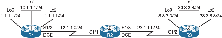
Figure 13-3 Configuring GRE/IPSec Tunnel Mode, Transport Mode, and S-VTI
Figure 13-3 illustrates the topology that will be used in the following lab.
Task 1
Configure a basic site-to-site IPSec VPN to protect traffic between the 1.1.1.0/24, 11.1.1.0/24, 2.2.2.0/24, and 22.2.2.0/24 networks using the policies shown in Table 13-3.
Table 13-3 Policy Guidelines for Configuring Task 1
Reachability is provided in the initial configuration.
Step 1. Configure ISAKMP using pre-shared authentication, MD5 hashing, DH group 2, and a PSK of “cisco” on both R1 and R3:
On R1:
R1(config)# crypto isakmp policy 10
R1(config-isakmp)# hash md5
R1(config-isakmp)# authentication pre-share
R1(config-isakmp)# group 2
R1(config-isakmp)# encryption 3des
R1(config-isakmp)# exit
On R3:
R3(config)# crypto isakmp policy 10
R3(config-isakmp)# hash md5
R3(config-isakmp)# authentication pre-share
R3(config-isakmp)# group 2
R3(config-isakmp)# encryption 3des
R3(config-isakmp)# exit
Step 2. Configure the ISAKMP key and identify the peer:
On R1:
R1(config)# crypto isakmp key cisco address 23.1.1.3
On R3:
R3(config)# crypto isakmp key cisco address 12.1.1.1
Step 3. Configure the IPSec transform set to use DES for encryption and MD5 for hashing:
On R1 and R3:
Rx(config)# crypto ipsec transform-set TSET esp-des esp-md5-hmac
Rx(cfg-config-trans)# exit
Step 4. Define interesting traffic. You can see how the crypto ACL can grow and grow. Can you imagine having 500 subnets trying to communicate with another 500 or more networks in a secure manner? The crypto ACL must be configured in a full mesh manner.
On R1:
R1(config)# access-list 100 permit ip host 1.1.1.1 host 3.3.3.3
R1(config)# access-list 100 permit ip host 1.1.1.1 host 30.3.3.3
R1(config)# access-list 100 permit ip host 1.1.1.1 host 33.3.3.3
R1(config)# access-list 100 permit ip host 10.1.1.1 host 3.3.3.3
R1(config)# access-list 100 permit ip host 10.1.1.1 host 30.3.3.3
R1(config)# access-list 100 permit ip host 10.1.1.1 host 33.3.3.3
R1(config)# access-list 100 permit ip host 11.1.1.1 host 3.3.3.3
R1(config)# access-list 100 permit ip host 11.1.1.1 host 30.3.3.3
R1(config)# access-list 100 permit ip host 11.1.1.1 host 33.3.3.3
On R3:
R3(config)# access-list 100 permit ip host 3.3.3.3 host 1.1.1.1
R3(config)# access-list 100 permit ip host 30.3.3.3 host 1.1.1.1
R3(config)# access-list 100 permit ip host 33.3.3.3 host 1.1.1.1
R3(config)# access-list 100 permit ip host 3.3.3.3 host 10.1.1.1
R3(config)# access-list 100 permit ip host 30.3.3.3 host 10.1.1.1
R3(config)# access-list 100 permit ip host 33.3.3.3 host 10.1.1.1
R3(config)# access-list 100 permit ip host 3.3.3.3 host 11.1.1.1
R3(config)# access-list 100 permit ip host 30.3.3.3 host 11.1.1.1
R3(config)# access-list 100 permit ip host 33.3.3.3 host 11.1.1.1
Step 5. Configure the crypto map and reference the peer, the crypto ACL, and the transform set configured in the previous steps:
On R1:
R1(config)# crypto map TST 10 ipsec-isakmp
R1(config-crypto-map)# set peer 23.1.1.3
R1(config-crypto-map)# match address 100
R1(config-crypto-map)# set transform-set TSET
On R3:
R3(config)# crypto map TST 10 ipsec-isakmp
R3(config-crypto-map)# set peer 12.1.1.1
R3(config-crypto-map)# match address 100
R3(config-crypto-map)# set transform-set TSET
Step 6. Apply the crypto map to the outside interface:
On R1:
R1(config)# interface Serial1/2
R1(config-if)# crypto map TST
On R3:
R3(config)# interface Serial1/2
R3(config-if)# crypto map TST
Let’s test the configuration:
On R1:
R1# ping 3.3.3.3 source loopback0
Type escape sequence to abort.
Sending 5, 100-byte ICMP Echos to 3.3.3.3, timeout is 2 seconds:
Packet sent with a source address of 1.1.1.1
.!!!!
Success rate is 80 percent (4/5), round-trip min/avg/max = 84/87/88 ms
R1# ping 3.3.3.3 source loopback1
Type escape sequence to abort.
Sending 5, 100-byte ICMP Echos to 3.3.3.3, timeout is 2 seconds:
Packet sent with a source address of 10.1.1.1
.!!!!
Success rate is 80 percent (4/5), round-trip min/avg/max = 84/87/88 ms
R1# ping 3.3.3.3 source loopback2
Type escape sequence to abort.
Sending 5, 100-byte ICMP Echos to 3.3.3.3, timeout is 2 seconds:
Packet sent with a source address of 11.1.1.1
.!!!!
Success rate is 80 percent (4/5), round-trip min/avg/max = 84/87/88 ms
R1# ping 30.3.3.3 source loopback0
Type escape sequence to abort.
Sending 5, 100-byte ICMP Echos to 30.3.3.3, timeout is 2 seconds:
Packet sent with a source address of 1.1.1.1
.!!!!
Success rate is 80 percent (4/5), round-trip min/avg/max = 84/87/88 ms
R1# ping 30.3.3.3 source loopback1
Type escape sequence to abort.
Sending 5, 100-byte ICMP Echos to 30.3.3.3, timeout is 2 seconds:
Packet sent with a source address of 10.1.1.1
.!!!!
Success rate is 80 percent (4/5), round-trip min/avg/max = 84/87/88 ms
R1# ping 30.3.3.3 source loopback2
Type escape sequence to abort.
Sending 5, 100-byte ICMP Echos to 30.3.3.3, timeout is 2 seconds:
Packet sent with a source address of 11.1.1.1
.!!!!
Success rate is 80 percent (4/5), round-trip min/avg/max = 84/87/88 ms
R1# ping 33.3.3.3 source loopback0
Type escape sequence to abort.
Sending 5, 100-byte ICMP Echos to 33.3.3.3, timeout is 2 seconds:
Packet sent with a source address of 1.1.1.1
.!!!!
Success rate is 80 percent (4/5), round-trip min/avg/max = 84/87/88 ms
R1# ping 33.3.3.3 source loopback1
Type escape sequence to abort.
Sending 5, 100-byte ICMP Echos to 33.3.3.3, timeout is 2 seconds:
Packet sent with a source address of 10.1.1.1
.!!!!
Success rate is 80 percent (4/5), round-trip min/avg/max = 84/87/88 ms
R1# ping 33.3.3.3 source loopback2
Type escape sequence to abort.
Sending 5, 100-byte ICMP Echos to 33.3.3.3, timeout is 2 seconds:
Packet sent with a source address of 11.1.1.1
.!!!!
Success rate is 80 percent (4/5), round-trip min/avg/max = 84/87/88 ms
R1# show crypto isakmp sa
IPv4 Crypto ISAKMP SA
dst src state conn-id status
23.1.1.3 12.1.1.1 QM_IDLE 1001 ACTIVE
IPv6 Crypto ISAKMP SA
R1# show crypto ipsec sa | include local|remote|#pkts
Crypto map tag: TST, local addr 12.1.1.1
local ident (addr/mask/prot/port): (1.1.1.1/255.255.255.255/0/0)
remote ident (addr/mask/prot/port): (3.3.3.3/255.255.255.255/0/0)
# pkts encaps: 4, # pkts encrypt: 4, # pkts digest: 4
# pkts decaps: 4, # pkts decrypt: 4, # pkts verify: 4
# pkts compressed: 0, # pkts decompressed: 0
# pkts not compressed: 0, # pkts compr. failed: 0
# pkts not decompressed: 0, # pkts decompress failed: 0
local crypto endpt.: 12.1.1.1, remote crypto endpt.: 23.1.1.3
local ident (addr/mask/prot/port): (10.1.1.1/255.255.255.255/0/0)
remote ident (addr/mask/prot/port): (3.3.3.3/255.255.255.255/0/0)
# pkts encaps: 4, # pkts encrypt: 4, # pkts digest: 4
# pkts decaps: 4, # pkts decrypt: 4, # pkts verify: 4
# pkts compressed: 0, # pkts decompressed: 0
# pkts not compressed: 0, # pkts compr. failed: 0
# pkts not decompressed: 0, # pkts decompress failed: 0
local crypto endpt.: 12.1.1.1, remote crypto endpt.: 23.1.1.3
local ident (addr/mask/prot/port): (11.1.1.1/255.255.255.255/0/0)
remote ident (addr/mask/prot/port): (3.3.3.3/255.255.255.255/0/0)
# pkts encaps: 4, # pkts encrypt: 4, # pkts digest: 4
# pkts decaps: 4, # pkts decrypt: 4, # pkts verify: 4
# pkts compressed: 0, # pkts decompressed: 0
# pkts not compressed: 0, # pkts compr. failed: 0
# pkts not decompressed: 0, # pkts decompress failed: 0
local crypto endpt.: 12.1.1.1, remote crypto endpt.: 23.1.1.3
local ident (addr/mask/prot/port): (1.1.1.1/255.255.255.255/0/0)
remote ident (addr/mask/prot/port): (30.3.3.3/255.255.255.255/0/0)
# pkts encaps: 4, # pkts encrypt: 4, # pkts digest: 4
# pkts decaps: 4, # pkts decrypt: 4, # pkts verify: 4
# pkts compressed: 0, # pkts decompressed: 0
# pkts not compressed: 0, # pkts compr. failed: 0
# pkts not decompressed: 0, # pkts decompress failed: 0
local crypto endpt.: 12.1.1.1, remote crypto endpt.: 23.1.1.3
local ident (addr/mask/prot/port): (1.1.1.1/255.255.255.255/0/0)
remote ident (addr/mask/prot/port): (33.3.3.3/255.255.255.255/0/0)
# pkts encaps: 4, # pkts encrypt: 4, # pkts digest: 4
# pkts decaps: 4, # pkts decrypt: 4, # pkts verify: 4
# pkts compressed: 0, # pkts decompressed: 0
# pkts not compressed: 0, # pkts compr. failed: 0
# pkts not decompressed: 0, # pkts decompress failed: 0
local crypto endpt.: 12.1.1.1, remote crypto endpt.: 23.1.1.3
local ident (addr/mask/prot/port): (10.1.1.1/255.255.255.255/0/0)
remote ident (addr/mask/prot/port): (30.3.3.3/255.255.255.255/0/0)
# pkts encaps: 4, # pkts encrypt: 4, # pkts digest: 4
# pkts decaps: 4, # pkts decrypt: 4, # pkts verify: 4
# pkts compressed: 0, # pkts decompressed: 0
# pkts not compressed: 0, # pkts compr. failed: 0
# pkts not decompressed: 0, # pkts decompress failed: 0
local crypto endpt.: 12.1.1.1, remote crypto endpt.: 23.1.1.3
local ident (addr/mask/prot/port): (11.1.1.1/255.255.255.255/0/0)
remote ident (addr/mask/prot/port): (30.3.3.3/255.255.255.255/0/0)
# pkts encaps: 4, # pkts encrypt: 4, # pkts digest: 4
# pkts decaps: 4, # pkts decrypt: 4, # pkts verify: 4
# pkts compressed: 0, # pkts decompressed: 0
# pkts not compressed: 0, # pkts compr. failed: 0
# pkts not decompressed: 0, # pkts decompress failed: 0
local crypto endpt.: 12.1.1.1, remote crypto endpt.: 23.1.1.3
local ident (addr/mask/prot/port): (10.1.1.1/255.255.255.255/0/0)
remote ident (addr/mask/prot/port): (33.3.3.3/255.255.255.255/0/0)
# pkts encaps: 4, # pkts encrypt: 4, # pkts digest: 4
# pkts decaps: 4, # pkts decrypt: 4, # pkts verify: 4
# pkts compressed: 0, # pkts decompressed: 0
# pkts not compressed: 0, # pkts compr. failed: 0
# pkts not decompressed: 0, # pkts decompress failed: 0
local crypto endpt.: 12.1.1.1, remote crypto endpt.: 23.1.1.3
local ident (addr/mask/prot/port): (11.1.1.1/255.255.255.255/0/0)
remote ident (addr/mask/prot/port): (33.3.3.3/255.255.255.255/0/0)
# pkts encaps: 4, # pkts encrypt: 4, # pkts digest: 4
# pkts decaps: 4, # pkts decrypt: 4, # pkts verify: 4
# pkts compressed: 0, # pkts decompressed: 0
# pkts not compressed: 0, # pkts compr. failed: 0
# pkts not decompressed: 0, # pkts decompress failed: 0
local crypto endpt.: 12.1.1.1, remote crypto endpt.: 23.1.1.3
This is definitely not scalable.
R1# show crypto engine connections active
Crypto Engine Connections
ID Type Algorithm Encrypt Decrypt LastSeqN IP-Address
1001 IKE MD5+3DES 0 0 0 12.1.1.1
2001 IPsec DES+MD5 0 4 4 12.1.1.1
2002 IPsec DES+MD5 4 0 0 12.1.1.1
2003 IPsec DES+MD5 0 4 4 12.1.1.1
2004 IPsec DES+MD5 4 0 0 12.1.1.1
2005 IPsec DES+MD5 0 4 4 12.1.1.1
2006 IPsec DES+MD5 4 0 0 12.1.1.1
2007 IPsec DES+MD5 0 4 4 12.1.1.1
2008 IPsec DES+MD5 4 0 0 12.1.1.1
2009 IPsec DES+MD5 0 4 4 12.1.1.1
2010 IPsec DES+MD5 4 0 0 12.1.1.1
2011 IPsec DES+MD5 0 4 4 12.1.1.1
2012 IPsec DES+MD5 4 0 0 12.1.1.1
2013 IPsec DES+MD5 0 4 4 12.1.1.1
2014 IPsec DES+MD5 4 0 0 12.1.1.1
2015 IPsec DES+MD5 0 4 4 12.1.1.1
2016 IPsec DES+MD5 4 0 0 12.1.1.1
2017 IPsec DES+MD5 0 4 4 12.1.1.1
2018 IPsec DES+MD5 4 0 0 12.1.1.1
You can see the number of SPIs in the output of the preceding show command. You can also see that the legacy site-to-site IPSec VPNs are not scalable when the number networks that need to communicate increases.
Task 2
You are getting ready to add 500 more subnets to R1 and 500 more subnets to R3. Therefore, you need to configure a scalable solution that does not require the need for crypto ACLs. You will use GRE/IPSEC with Tunnel Mode to accomplish this task.
Because you need to totally cross-eliminate crypto ACLs, you can configure a GRE tunnel and encrypt all traffic that traverses the tunnel. Let’s configure it:
Step 1. Configure the GRE tunnels.
When you’re configuring the GRE tunnels, the tunnel source must reference the outside interface of the local router, and the tunnel destination must be the outside interface of the peer router. Also, the tunnel IP address should be a private IP address.
On R1:
R1(config)# interface tunnel13
R1(config-if)# ip address 10.1.13.1 255.255.255.0
R1(config-if)# tunnel source 12.1.1.1
R1(config-if)# tunnel destination 23.1.1.3
On R3:
R3(config)# interface tunnel31
R3(config-if)# ip address 10.1.13.3 255.255.255.0
R3(config-if)# tunnel source 23.1.1.3
R3(config-if)# tunnel destination 12.1.1.1
Step 2. Use an Interior Gateway Protocol (IGP) to advertise the networks in through the tunnel.
In this case, EIGRP AS 100 is used, but you can use any IGP to accomplish this step.
On R1:
R1(config)# router eigrp 100
R1(config-router)# netw 10.1.13.1 0.0.0.0
On R3:
R3(config)# router eigrp 100
R3(config-router)# netw 10.1.13.3 0.0.0.0
You should see the following console message:
%DUAL-5-NBRCHANGE: EIGRP-IPv4 100: Neighbor 10.1.13.1 (Tunnel31) is up:
new adjacency
Let’s verify the configuration:
On R3:
R3# show ip route eigrp | begin Gate
Gateway of last resort is 23.1.1.2 to network 0.0.0.0
1.0.0.0/24 is subnetted, 1 subnets
D 1.1.1.0 [90/27008000] via 10.1.13.1, 00:02:15, Tunnel31
10.0.0.0/8 is variably subnetted, 3 subnets, 2 masks
D 10.1.1.0/24 [90/27008000] via 10.1.13.1, 00:02:15, Tunnel31
11.0.0.0/24 is subnetted, 1 subnets
D 11.1.1.0 [90/27008000] via 10.1.13.1, 00:02:15, Tunnel31
Step 3. We need to delete the crypto ACLs and crypto maps. To remove the crypto map we previously applied to the interfaces:
On R1 and R3:
Rx(config)# no access-list 100
Rx(config)# interface Serial1/2
Rx(config-if)# no crypto map TST
Rx(config-if)# exit
Rx(config)# no crypto map TST
Step 4. Configure a crypto IPSec profile and reference the transform set:
On R1 and R3:
Rx(config)# crypto ipsec profile ABC
Rx(ipsec-profile)# set transform-set TSET
Step 5. Apply the crypto IPSec profile to the tunnel interface:
On R1:
R1(config)# interface tunnel13
R1(config-if)# tunnel protection ipsec profile ABC
Note EIGRP adjacency will go down because you are encrypting on one end and not the other. You should also see ISAKMP being enabled in the following console message:
%CRYPTO-6-ISAKMP_ON_OFF: ISAKMP is ON
%DUAL-5-NBRCHANGE: EIGRP-IPv4 100: Neighbor 10.1.13.3 (Tunnel13) is down:
holding time expired
On R3:
R3(config)# interface tunnel31
R3(config-if)# tunnel protection ipsec profile ABC
You should see the following console messages:
%CRYPTO-6-ISAKMP_ON_OFF: ISAKMP is ON
%DUAL-5-NBRCHANGE: EIGRP-IPv4 100: Neighbor 10.1.13.1 (Tunnel31) is up:
new adjacency
The tunnel protection ipsec profile command states that any traffic that traverses the tunnel should be encrypted with the IPSec profile called ABC.
Note In the legacy configuration, the crypto map had the following commands:
![]() Set Transform-set: In the legacy configuration, this is done in the crypto ipsec profile.
Set Transform-set: In the legacy configuration, this is done in the crypto ipsec profile.
![]() Set address: This references the interesting traffic, and we saw in the previous task that this configuration is not scalable at all. In this configuration, the crypto ACLs are no longer required because any traffic that traverses the tunnel will be encrypted, and as long as the configured routing protocol is pointing to the tunnel interface, all traffic from all subnets will be affected.
Set address: This references the interesting traffic, and we saw in the previous task that this configuration is not scalable at all. In this configuration, the crypto ACLs are no longer required because any traffic that traverses the tunnel will be encrypted, and as long as the configured routing protocol is pointing to the tunnel interface, all traffic from all subnets will be affected.
![]() Set peer: In the legacy configuration, this is achieved through the tunnel destination command when the actual GRE tunnel is configured.
Set peer: In the legacy configuration, this is achieved through the tunnel destination command when the actual GRE tunnel is configured.
Step 6. Now we need to verify that GRE/IPSec are running on the tunnels and that we are using Tunnel Mode:
R3# show crypto ipsec sa | section spi
current outbound spi: 0xFA948BE8(4204039144)
spi: 0xD090B49D(3499144349)
transform: esp-des esp-md5-hmac ,
in use settings ={Tunnel, }
conn id: 2019, flow_id: NETGX:19, sibling_flags 80000046, crypto map: Tunnel31-head-0
sa timing: remaining key lifetime (k/sec): (4598347/3082)
IV size: 8 bytes
replay detection support: Y
Status: ACTIVE
spi: 0xFA948BE8(4204039144)
transform: esp-des esp-md5-hmac ,
in use settings ={Tunnel, }
conn id: 2020, flow_id: NETGX:20, sibling_flags 80000046, crypto map: Tunnel31-head-0
sa timing: remaining key lifetime (k/sec): (4598347/3082)
IV size: 8 bytes
replay detection support: Y
Status: ACTIVE
R3# show interface tunnel31 | include Tunnel protocol
Tunnel protocol/transport GRE/IP
Task 3
After implementing the previous solution, you realize that every packet has duplicate IP addresses in the header. You need to keep the GRE tunnel but eliminate the duplicate IP addresses in the header of every packet.
To resolve this task, you must change the mode to Transport. Let’s do that now:
On R1 and R3:
Rx(config)# crypto ipsec transform-set TSET esp-des esp-md5-hmac
Rx(cfg-crypto-trans)# mode transport
To verify this, you must clear crypto ipsec sas:
On Both Routers:
Rx# clear crypto sa
R1# show crypto ipsec sa
interface: Tunnel13
Crypto map tag: Tunnel13-head-0, local addr 12.1.1.1
protected vrf: (none)
local ident (addr/mask/prot/port): (12.1.1.1/255.255.255.255/47/0)
remote ident (addr/mask/prot/port): (23.1.1.3/255.255.255.255/47/0)
current_peer 23.1.1.3 port 500
PERMIT, flags={origin_is_acl,}
# pkts encaps: 9, # pkts encrypt: 9, # pkts digest: 9
# pkts decaps: 7, # pkts decrypt: 7, # pkts verify: 7
# pkts compressed: 0, # pkts decompressed: 0
# pkts not compressed: 0, # pkts compr. failed: 0
# pkts not decompressed: 0, # pkts decompress failed: 0
# send errors 0, # recv errors 0
local crypto endpt.: 12.1.1.1, remote crypto endpt.: 23.1.1.3
path mtu 1500, ip mtu 1500, ip mtu idb Serial1/2
current outbound spi: 0x58BF5B22(1488935714)
PFS (Y/N): N, DH group: none
inbound esp sas:
spi: 0x31C3E03A(834920506)
transform: esp-des esp-md5-hmac ,
in use settings ={Transport, }
conn id: 2025, flow_id: NETGX:25, sibling_flags 80000006, crypto map: Tunnel13-head-0
sa timing: remaining key lifetime (k/sec): (4430829/3568)
IV size: 8 bytes
replay detection support: Y
Status: ACTIVE
inbound ah sas:
inbound pcp sas:
outbound esp sas:
spi: 0x58BF5B22(1488935714)
transform: esp-des esp-md5-hmac ,
in use settings ={Transport, }
conn id: 2026, flow_id: NETGX:26, sibling_flags 80000006, crypto map: Tunnel13-head-0
sa timing: remaining key lifetime (k/sec): (4430829/3568)
IV size: 8 bytes
replay detection support: Y
Status: ACTIVE
outbound ah sas:
outbound pcp sas:
The transport protocol is still GRE. Let’s verify this:
On R1:
R1# show interface tunnel13 | include Tunnel protocol
Tunnel protocol/transport GRE/IP
Task 4
Reconfigure R1 and R3 so that the tunnel protocol is IPSec; this way, the extra GRE overhead is no longer there.
In order to eliminate GRE altogether, you can change the tunnel mode to IPSec. Let’s configure this and verify:
On R1:
R1(config)# interface tunnel13
R1(config-if)# tunnel mode ipsec ipv4
You should see the following console message:
%DUAL-5-NBRCHANGE: EIGRP-IPv4 100: Neighbor 10.1.13.3 (Tunnel13) is down: holding time expired
On R3:
R3(config)# interface tunnel31
R3(config-if)# tunnel mode ipsec ipv4
You should see EIGRP coming up again. This means that packets are being encrypted.
%DUAL-5-NBRCHANGE: EIGRP-IPv4 100: Neighbor 10.1.13.1 (Tunnel31) is up: new adjacency
Let’s verify the configuration:
On R1:
R1# show crypto ipsec sa
interface: Tunnel13
Crypto map tag: Tunnel13-head-0, local addr 12.1.1.1
protected vrf: (none)
local ident (addr/mask/prot/port): (0.0.0.0/0.0.0.0/0/0)
remote ident (addr/mask/prot/port): (0.0.0.0/0.0.0.0/0/0)
current_peer 23.1.1.3 port 500
PERMIT, flags={origin_is_acl,}
# pkts encaps: 26, # pkts encrypt: 26, # pkts digest: 26
# pkts decaps: 27, # pkts decrypt: 27, # pkts verify: 27
# pkts compressed: 0, # pkts decompressed: 0
# pkts not compressed: 0, # pkts compr. failed: 0
# pkts not decompressed: 0, # pkts decompress failed: 0
# send errors 8, # recv errors 0
local crypto endpt.: 12.1.1.1, remote crypto endpt.: 23.1.1.3
path mtu 1500, ip mtu 1500, ip mtu idb Serial1/2
current outbound spi: 0x653D25F9(1698506233)
PFS (Y/N): N, DH group: none
inbound esp sas:
spi: 0xF08E7802(4035868674)
transform: esp-des esp-md5-hmac ,
in use settings ={Tunnel, }
conn id: 2029, flow_id: NETGX:29, sibling_flags 80000046, crypto map: Tunnel13-head-0
sa timing: remaining key lifetime (k/sec): (4571849/3511)
IV size: 8 bytes
replay detection support: Y
Status: ACTIVE
inbound ah sas:
inbound pcp sas:
outbound esp sas:
spi: 0x653D25F9(1698506233)
transform: esp-des esp-md5-hmac ,
in use settings ={Tunnel, }
conn id: 2030, flow_id: NETGX:30, sibling_flags 80000046, crypto map: Tunnel13-head-0
sa timing: remaining key lifetime (k/sec): (4571849/3511)
IV size: 8 bytes
replay detection support: Y
Status: ACTIVE
outbound ah sas:
outbound pcp sas:
R1# show interface tunnel13 | include Tunnel protocol
Tunnel protocol/transport IPSEC/IP
Do not forget to make the following configuration on both routers in the topology.
Rx(config)# crypto ipsec transform-set TSET esp-des esp-md5-hmac
Rx(cfg-crypto-trans)# mode tunnel
Rx# clear crypto sa
You should wait for the tunnel to come up:
R1# show crypto ipsec sa
interface: Tunnel13
Crypto map tag: Tunnel13-head-0, local addr 12.1.1.1
protected vrf: (none)
local ident (addr/mask/prot/port): (0.0.0.0/0.0.0.0/0/0)
remote ident (addr/mask/prot/port): (0.0.0.0/0.0.0.0/0/0)
current_peer 23.1.1.3 port 500
PERMIT, flags={origin_is_acl,}
# pkts encaps: 14, # pkts encrypt: 14, # pkts digest: 14
# pkts decaps: 13, # pkts decrypt: 13, # pkts verify: 13
# pkts compressed: 0, # pkts decompressed: 0
# pkts not compressed: 0, # pkts compr. failed: 0
# pkts not decompressed: 0, # pkts decompress failed: 0
# send errors 0, # recv errors 0
local crypto endpt.: 12.1.1.1, remote crypto endpt.: 23.1.1.3
path mtu 1500, ip mtu 1500, ip mtu idb Serial1/2
current outbound spi: 0x8CD7122B(2362905131)
PFS (Y/N): N, DH group: none
inbound esp sas:
spi: 0xD5DFBB05(3588209413)
transform: esp-des esp-md5-hmac ,
in use settings ={Tunnel, }
conn id: 2031, flow_id: NETGX:31, sibling_flags 80000046, crypto map: Tunnel13-head-0
sa timing: remaining key lifetime (k/sec): (4580543/3568)
IV size: 8 bytes
replay detection support: Y
Status: ACTIVE
inbound ah sas:
inbound pcp sas:
outbound esp sas:
spi: 0x8CD7122B(2362905131)
transform: esp-des esp-md5-hmac ,
in use settings ={Tunnel, }
conn id: 2032, flow_id: NETGX:32, sibling_flags 80000046, crypto map: Tunnel13-head-0
sa timing: remaining key lifetime (k/sec): (4580543/3568)
IV size: 8 bytes
replay detection support: Y
Status: ACTIVE
outbound ah sas:
outbound pcp sas:
Erase the startup configuration of the routers and reload them before proceeding to the next lab.
Lab 13-4: Protecting DMVPN Tunnels
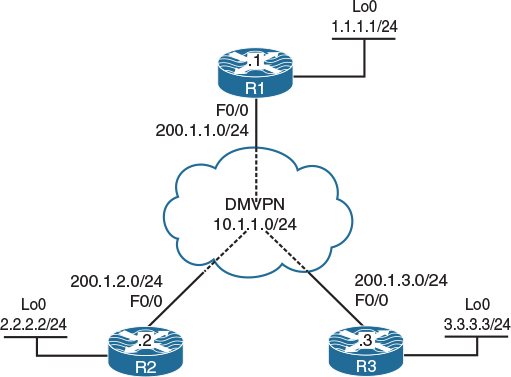
Figure 13-4 Configuring Protecting DMVPN Tunnels
Figure 13-4 illustrates the topology that will be used in the following lab.
Task 1
SW1 represents the Internet; configure the ports on the switch based on the following and then enable IP routing:
![]() F0/1: 200.1.1.10/24
F0/1: 200.1.1.10/24
![]() F0/2: 200.1.2.10/24
F0/2: 200.1.2.10/24
![]() F0/3: 200.1.3.10/24
F0/3: 200.1.3.10/24
On SW1:
SW1(config)# interface FastEthernet 0/1
SW1(config-if)# no switchport
SW1(config-if)# ip address 200.1.1.10 255.255.255.0
SW1(config-if)# no shutdown
SW1(config)# interface FastEthernet 0/2
SW1(config-if)# no switchport
SW1(config-if)# ip address 200.1.2.10 255.255.255.0
SW1(config-if)# no shutdown
SW1(config)# interface FastEthernet 0/3
SW1(config-if)# no switchport
SW1(config-if)# ip address 200.1.3.10 255.255.255.0
SW1(config-if)# no shutdown
SW1(config)# ip routing
Task 2
Configure the F0/0 and loopback0 interfaces of R1, R2, and R3 based on the configurations shown in Table 13-4.
Table 13-4 Configurations for Task 2
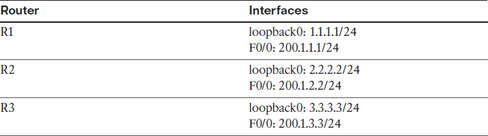
Ensure that these routers have full reachability to each other using static routes:
On R1:
R1(config)# interface loopback0
R1(config-if)# ip address 1.1.1.1 255.255.255.0
R1(config)# interface FastEthernet 0/0
R1(config-if)# ip address 200.1.1.1 255.255.255.0
R1(config-if)# no shutdown
R1(config)# ip route 200.1.2.0 255.255.255.0 200.1.1.10
R1(config)# ip route 200.1.3.0 255.255.255.0 200.1.1.10
On R2:
R2(config)# interface loopback0
R2(config-if)# ip address 2.2.2.2 255.255.255.0
R2(config)# interface FastEthernet 0/0
R2(config-if)# ip address 200.1.2.2 255.255.255.0
R2(config-if)# no shutdown
R2(config)# ip route 200.1.1.0 255.255.255.0 200.1.2.10
R2(config)# ip route 200.1.3.0 255.255.255.0 200.1.2.10
On R3:
R3(config)# interface loopback 0
R3(config-if)# ip address 3.3.3.3 255.255.255.0
R3(config)# interface FastEthernet 0/0
R3(config-if)# ip address 200.1.3.3 255.255.255.0
R3(config-if)# no shutdown
R3(config)# ip route 200.1.1.0 255.255.255.0 200.1.3.10
R3(config)# ip route 200.1.2.0 255.255.255.0 200.1.3.10
Let’s verify the configuration:
On R1:
R1# ping 200.1.2.2
Type escape sequence to abort.
Sending 5, 100-byte ICMP Echos to 200.1.2.2, timeout is 2 seconds:
!!!!!
Success rate is 100 percent (5/5), round-trip min/avg/max = 1/2/4 ms
R1# ping 200.1.3.3
Type escape sequence to abort.
Sending 5, 100-byte ICMP Echos to 200.1.3.3, timeout is 2 seconds:
!!!!!
Success rate is 100 percent (5/5), round-trip min/avg/max = 1/2/4 ms
On R2:
R2# ping 200.1.3.3
Type escape sequence to abort.
Sending 5, 100-byte ICMP Echos to 200.1.3.3, timeout is 2 seconds:
!!!!!
Success rate is 100 percent (5/5), round-trip min/avg/max = 1/2/4 ms
Task 3
Configure DMVPN Phase 2 such that R1 is the hub. R2 and R3 should be configured as the spokes. You should use 10.1.1.x/24, where x is the router number. If this configuration is performed correctly, these routers should have full reachability to all loopback interfaces and tunnel endpoints. You should not configure static mappings on the hub router to accomplish this task. Use EIGRP to provide reachability.
On R1:
R1(config)# interface tunnel123
R1(config-if)# ip address 10.1.1.1 255.255.255.0
R1(config-if)# tunnel source FastEthernet 0/0
R1(config-if)# tunnel mode gre multipoint
R1(config-if)# ip nhrp network-id 111
R1(config-if)# ip nhrp map multicast dynamic
On R2:
R2(config)# interface tunnel123
R2(config-if)# ip address 10.1.1.2 255.255.255.0
R2(config-if)# tunnel source FastEthernet 0/0
R2(config-if)# tunnel mode gre multipoint
R2(config-if)# ip nhrp network-id 222
R2(config-if)# ip nhrp nhs 10.1.1.1
R2(config-if)# ip nhrp map 10.1.1.1 200.1.1.1
On R3:
R3(config)# interface tunnel123
R3(config-if)# ip address 10.1.1.3 255.255.255.0
R3(config-if)# tunnel source FastEthernet 0/0
R3(config-if)# tunnel mode gre multipoint
R3(config-if)# ip nhrp network-id 333
R3(config-if)# ip nhrp nhs 10.1.1.1
R3(config-if)# ip nhrp map 10.1.1.1 200.1.1.1
Let’s verify the configuration:
On R1:
R1# show ip nhrp
10.1.1.2/32 via 10.1.1.2
Tunnel123 created 00:03:43, expire 01:56:16
Type: dynamic, Flags: unique registered
NBMA address: 200.1.2.2
10.1.1.3/32 via 10.1.1.3
Tunnel123 created 00:02:18, expire 01:57:41
Type: dynamic, Flags: unique registered
NBMA address: 200.1.3.3
R1# show dmvpn detail
Legend: Attrb --> S - Static, D - Dynamic, I - Incomplete
N - NATed, L - Local, X - No Socket
# Ent --> Number of NHRP entries with same NBMA peer
NHS Status: E --> Expecting Replies, R --> Responding, W --> Waiting
UpDn Time --> Up or Down Time for a Tunnel
==========================================================================
Interface Tunnel123 is up/up, Addr. is 10.1.1.1, VRF ""
Tunnel Src./Dest. addr: 200.1.1.1/MGRE, Tunnel VRF ""
Protocol/Transport: "multi-GRE/IP", Protect ""
Interface State Control: Disabled
Type:Hub, Total NBMA Peers (v4/v6): 2
# Ent Peer NBMA Addr Peer Tunnel Add State UpDn Tm Attrb Target Network
----- --------------- --------------- ----- -------- ----- ---------------
1 200.1.2.2 10.1.1.2 UP 00:04:47 D 10.1.1.2/32
1 200.1.3.3 10.1.1.3 UP 00:03:22 D 10.1.1.3/32
Crypto Session Details:
-------------------------------------------------------------------
Pending DMVPN Sessions:
R1# ping 10.1.1.2
Type escape sequence to abort.
Sending 5, 100-byte ICMP Echos to 10.1.1.2, timeout is 2 seconds:
!!!!!
Success rate is 100 percent (5/5), round-trip min/avg/max = 1/3/4 ms
R1# ping 10.1.1.3
Type escape sequence to abort.
Sending 5, 100-byte ICMP Echos to 10.1.1.3, timeout is 2 seconds:
!!!!!
Success rate is 100 percent (5/5), round-trip min/avg/max = 1/2/4 ms
R1(config)# router eigrp 100
R1(config-router)# network 1.1.1.1 0.0.0.0
R1(config-router)# network 10.1.1.1 0.0.0.0
R1(config)# interface tunnel123
R1(config-if)# no ip split-horizon eigrp 100
R1(config-if)# no ip next-hop-self eigrp 100
On R2:
R2(config)# router eigrp 100
R2(config-router)# network 2.2.2.2 0.0.0.0
R2(config-router)# network 10.1.1.2 0.0.0.0
You should see the following console message:
%DUAL-5-NBRCHANGE: EIGRP-IPv4 100: Neighbor 10.1.1.1 (Tunnel123) is up:
new adjacency
R2(config)# interface tunne123
R2(config-if)# ip nhrp map multicast 200.1.1.1
On R3:
R3(config)# router eigrp 100
R3(config-router)# network 3.3.3.3 0.0.0.0
R3(config-router)# network 10.1.1.3 0.0.0.0
You should also see this console message:
%DUAL-5-NBRCHANGE: EIGRP-IPv4 100: Neighbor 10.1.1.1 (Tunnel123) is up: new adjacency
R3(config)# interface tunnel123
R3(config-if)# ip nhrp map multicast 200.1.1.1
Let’s verify the configuration:
On R2:
R2# show ip route eigrp | begin Gate
Gateway of last resort is not set
1.0.0.0/24 is subnetted, 1 subnets
D 1.1.1.0 [90/27008000] via 10.1.1.1, 00:02:19, Tunnel123
3.0.0.0/24 is subnetted, 1 subnets
D 3.3.3.0 [90/28288000] via 10.1.1.3, 00:01:31, Tunnel123
R2# ping 1.1.1.1
Type escape sequence to abort.
Sending 5, 100-byte ICMP Echos to 1.1.1.1, timeout is 2 seconds:
!!!!!
Success rate is 100 percent (5/5), round-trip min/avg/max = 1/2/4 ms
R2# ping 3.3.3.3
Type escape sequence to abort.
Sending 5, 100-byte ICMP Echos to 3.3.3.3, timeout is 2 seconds:
!!!!!
Success rate is 100 percent (5/5), round-trip min/avg/max = 4/4/8 ms
Task 4
Protect the traffic between 1.1.1.0/24, 2.2.2.0/24, and 3.3.3.0/24 using an IPSec VPN based on the policy shown in Table 13-5.
Table 13-5 Policy Guidelines for Configuring Task 4
Let’s go through the steps.
First, we begin by configuring IKE Phase 1:
On R1:
R1(config)# crypto isakmp policy 10
R1(config-isakmp)# hash md5
R1(config-isakmp)# authentication pre-share
R1(config-isakmp)# group 2
R1(config-isakmp)# encryption 3des
Note The address is set to 0.0.0.0 because the edge devices may acquire different IP addresses, and/or spoke-to-spoke communication may occur between any spokes. Therefore, the IP address must be set to 0.0.0.0:
R1(config)# crypto isakmp key cisco address 0.0.0.0
Now with that done, we can create a transform set based on the requirement in the task:
R1(config)# crypto ipsec transform-set TSET esp-des esp-md5-hmac
R1(cfg-crypto-trans)# mode transport
Next, we configure crypto ipsec profile to reference the transform set:
R1(config)# crypto ipsec profile TST
R1(ipsec-profile)# set transform-set TSET
The crypto ipsec profile is configured in the tunnel to protect all traffic traversing the tunnel interface:
R1(config)# interface tunnel123
R1(config-if)# tunnel protection ipsec profile TST
Once this is configured on R1, you will see that ISAKMP is enabled. Because this is the only site configured, EIGRP neighbor adjacency will be lost to R2 and R3:
%CRYPTO-6-ISAKMP_ON_OFF: ISAKMP is ON
%DUAL-5-NBRCHANGE: EIGRP-IPv4 100: Neighbor 10.1.1.2 (Tunnel123) is down:
holding time expired
%DUAL-5-NBRCHANGE: EIGRP-IPv4 100: Neighbor 10.1.1.3 (Tunnel123) is down:
holding time expired
You will also see the following console messages stating that you are receiving packets that are not encrypted:
%CRYPTO-4-RECVD_PKT_NOT_IPSEC: Rec'd packet not an IPSEC packet. (ip)
vrf/dest_addr= /200.1.1.1, src_addr= 200.1.2.2, prot= 47
On R2:
R2(config)# crypto isakmp policy 10
R2(config-isakmp)# hash md5
R2(config-isakmp)# authentication pre-share
R2(config-isakmp)# group 2
R2(config-isakmp)# encryption 3des
R2(config)# crypto isakmp key cisco address 0.0.0.0
R2(config)# crypto ipsec transform-set TSET esp-des esp-md5-hmac
R2(cfg-crypto-trans)# mode transport
R2(config)# crypto ipsec profile TST
R2(ipsec-profile)# set transform-set TSET
R2(config)# interface tunnel 123
R2(config-if)# tunnel protection ipsec profile TST
You should see the following console message:
%CRYPTO-6-ISAKMP_ON_OFF: ISAKMP is ON
%DUAL-5-NBRCHANGE: EIGRP-IPv4 100: Neighbor 10.1.1.1 (Tunnel123) is up:
new adjacency
On R3:
R3(config)# crypto isakmp policy 10
R3(config-isakmp)# hash md5
R3(config-isakmp)# authentication pre-share
R3(config-isakmp)# group 2
R3(config-isakmp)# encryption 3des
R3(config)# crypto isakmp key cisco address 0.0.0.0
R3(config)# crypto ipsec transform-set TSET esp-des esp-md5-hmac
R3(cfg-crypto-trans)# mode transport
R3(config)# crypto ipsec profile TST
R3(ipsec-profile)# set transform-set TSET
R3(config)# interface tunnel 123
R3(config-if)# tunnel protection ipsec profile TST
%CRYPTO-6-ISAKMP_ON_OFF: ISAKMP is ON
%DUAL-5-NBRCHANGE: EIGRP-IPv4 100: Neighbor 10.1.1.1 (Tunnel123) is up:
new adjacency
Let’s verify the configuration:
On R2:
R2# show crypto ipsec sa
interface: Tunnel123
Crypto map tag: Tunnel123-head-0, local addr 200.1.2.2
protected vrf: (none)
local ident (addr/mask/prot/port): (200.1.2.2/255.255.255.255/47/0)
remote ident (addr/mask/prot/port): (200.1.1.1/255.255.255.255/47/0)
current_peer 200.1.1.1 port 500
PERMIT, flags={origin_is_acl,}
# pkts encaps: 176, # pkts encrypt: 176, # pkts digest: 176
# pkts decaps: 178, # pkts decrypt: 178, # pkts verify: 178
# pkts compressed: 0, # pkts decompressed: 0
# pkts not compressed: 0, # pkts compr. failed: 0
# pkts not decompressed: 0, # pkts decompress failed: 0
# send errors 0, # recv errors 0
local crypto endpt.: 200.1.2.2, remote crypto endpt.: 200.1.1.1
path mtu 1500, ip mtu 1500, ip mtu idb (none)
current outbound spi: 0x97BEF376(2545873782)
PFS (Y/N): N, DH group: none
inbound esp sas:
spi: 0x7AC150C4(2059489476)
transform: esp-des esp-md5-hmac ,
in use settings ={Transport, }
conn id: 2003, flow_id: NETGX:3, sibling_flags 80000006, crypto map: Tunnel123-head-0
sa timing: remaining key lifetime (k/sec): (4428305/2843)
IV size: 8 bytes
replay detection support: Y
Status: ACTIVE
inbound ah sas:
inbound pcp sas:
outbound esp sas:
spi: 0x97BEF376(2545873782)
transform: esp-des esp-md5-hmac ,
in use settings ={Transport, }
conn id: 2004, flow_id: NETGX:4, sibling_flags 80000006, crypto map: Tunnel123-head-0
sa timing: remaining key lifetime (k/sec): (4428305/2843)
IV size: 8 bytes
replay detection support: Y
Status: ACTIVE
outbound ah sas:
outbound pcp sas:
protected vrf: (none)
local ident (addr/mask/prot/port): (200.1.2.2/255.255.255.255/47/0)
remote ident (addr/mask/prot/port): (200.1.3.3/255.255.255.255/47/0)
current_peer 200.1.3.3 port 500
PERMIT, flags={origin_is_acl,}
# pkts encaps: 0, # pkts encrypt: 0, # pkts digest: 0
# pkts decaps: 0, # pkts decrypt: 0, # pkts verify: 0
# pkts compressed: 0, # pkts decompressed: 0
# pkts not compressed: 0, # pkts compr. failed: 0
# pkts not decompressed: 0, # pkts decompress failed: 0
# send errors 0, # recv errors 0
local crypto endpt.: 200.1.2.2, remote crypto endpt.: 200.1.3.3
path mtu 1500, ip mtu 1500, ip mtu idb (none)
current outbound spi: 0x539AB1EC(1402647020)
PFS (Y/N): N, DH group: none
inbound esp sas:
spi: 0xCC3D2892(3426560146)
transform: esp-des esp-md5-hmac ,
in use settings ={Transport, }
conn id: 2007, flow_id: NETGX:7, sibling_flags 80000006, crypto map: Tunnel123-head-0
sa timing: remaining key lifetime (k/sec): (4529448/2854)
IV size: 8 bytes
replay detection support: Y
Status: ACTIVE
inbound ah sas:
inbound pcp sas:
outbound esp sas:
spi: 0x539AB1EC(1402647020)
transform: esp-des esp-md5-hmac ,
in use settings ={Transport, }
conn id: 2008, flow_id: NETGX:8, sibling_flags 80000006, crypto map: Tunnel123-head-0
sa timing: remaining key lifetime (k/sec): (4529448/2854)
IV size: 8 bytes
replay detection support: Y
Status: ACTIVE
outbound ah sas:
outbound pcp sas:
R2# show crypto isakmp sa
IPv4 Crypto ISAKMP SA
dst src state conn-id status
200.1.2.2 200.1.3.3 QM_IDLE 1003 ACTIVE
200.1.2.2 200.1.1.1 QM_IDLE 1002 ACTIVE
200.1.1.1 200.1.2.2 QM_IDLE 1001 ACTIVE
200.1.3.3 200.1.2.2 QM_IDLE 1004 ACTIVE
IPv6 Crypto ISAKMP SA
R2# ping 3.3.3.3 source loopback0
Type escape sequence to abort.
Sending 5, 100-byte ICMP Echos to 3.3.3.3, timeout is 2 seconds:
Packet sent with a source address of 2.2.2.2
!!!!!
Success rate is 100 percent (5/5), round-trip min/avg/max = 4/4/4 ms
R2# show crypto ipsec sa | include local|remote|#pkts
Crypto map tag: Tunnel123-head-0, local addr 200.1.2.2
local ident (addr/mask/prot/port): (200.1.2.2/255.255.255.255/47/0)
remote ident (addr/mask/prot/port): (200.1.1.1/255.255.255.255/47/0)
# pkts encaps: 304, # pkts encrypt: 304, # pkts digest: 304
# pkts decaps: 306, # pkts decrypt: 306, # pkts verify: 306
# pkts compressed: 0, # pkts decompressed: 0
# pkts not compressed: 0, # pkts compr. failed: 0
# pkts not decompressed: 0, # pkts decompress failed: 0
local crypto endpt.: 200.1.2.2, remote crypto endpt.: 200.1.1.1
local ident (addr/mask/prot/port): (200.1.2.2/255.255.255.255/47/0)
remote ident (addr/mask/prot/port): (200.1.3.3/255.255.255.255/47/0)
# pkts encaps: 5, # pkts encrypt: 5, # pkts digest: 5
# pkts decaps: 5, # pkts decrypt: 5, # pkts verify: 5
# pkts compressed: 0, # pkts decompressed: 0
# pkts not compressed: 0, # pkts compr. failed: 0
# pkts not decompressed: 0, # pkts decompress failed: 0
local crypto endpt.: 200.1.2.2, remote crypto endpt.: 200.1.3.3
Erase the startup configuration of the routers and reload them before proceeding to the next lab.