Chapter 8 OSPF
Lab 8-1: Advertising Networks
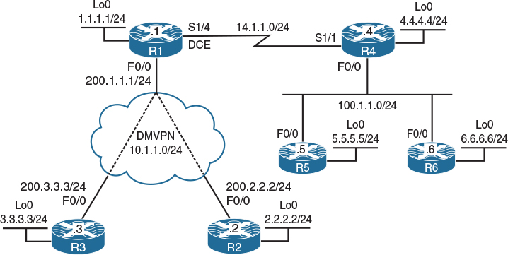
Figure 8-1 Advertising Networks
Figure 8-1 illustrates the topology that will used in the following tasks.
Task 1
Configure the connections between R4, R5, and R6 and run OSPF Area 0 on the f0/0 and the lo0 interfaces of these three routers. Configure the router IDs to be 0.0.0.x, where x is the router number. The loopback interfaces should be advertised with their correct mask.
On SW1:
SW1(config)# interface range FastEthernet0/4-6
SW1(config-if-range)# switchport
SW1(config-if-range)# switchport mode access
SW1(config-if-range)# switchport access vlan 456
SW1(config-if-range)# no shutdown
On R4:
R4(config)# interface loopback0
R4(config-if)# ip address 4.4.4.4 255.255.255.0
R4(config-if)# ip ospf network point-to-point
R4(config)# interface FastEthernet0/0
R4(config-if)# ip address 100.1.1.4 255.255.255.0
R4(config-if)# no shutdown
Let’s configure OSPF:
R4(config)# router ospf 1
In the following configuration, OSPF’s router-id is set to 0.0.0.4. In OSPF, the router ID uniquely identifies the router within the entire routing domain and must be unique within the entire OSPF routing domain.
The OSPF router ID is a 32-bit dotted decimal value, it is not an IP address. However, since IP addresses are also 32-bit dotted decimal values, a value that looks like an IP address can also be used as the OSPF router ID. If the router-id is not configured, the numerically highest IP address of any loopback interface will be chosen as the router ID; if one does not exist, then the highest IP address configured on the local router will be chosen as the OSPF router ID. It’s a good practice to always configure OSPF’s router-id, unless you are in the CCIE lab and the task states not to.
R4(config-router)# router-id 0.0.0.4
In OSPF, the network statement can be configured in different ways; the following network statement could have been configured in the following ways:
![]() network 0.0.0.0 0.0.0.0 area 0: This network statement means that the existing and future interface(s) that have an IP address will run in Area 0. Remember that if an interface is redistributed into the OSPF routing protocol, the redistributed interface will show up in the routing table as an intra-area route and not an external route, because intra-area is preferred over inter-area, which in turn is preferred over external routes.
network 0.0.0.0 0.0.0.0 area 0: This network statement means that the existing and future interface(s) that have an IP address will run in Area 0. Remember that if an interface is redistributed into the OSPF routing protocol, the redistributed interface will show up in the routing table as an intra-area route and not an external route, because intra-area is preferred over inter-area, which in turn is preferred over external routes.
![]() network 100.0.0.0 0.255.255.255 area 0: This network statement means that any subnet within the major network (100.0.0.0/8) should run in Area 0.
network 100.0.0.0 0.255.255.255 area 0: This network statement means that any subnet within the major network (100.0.0.0/8) should run in Area 0.
![]() network 100.1.1.0 0.0.0.255 area 0: This network statement means that any host within network 100.1.1.0/24 will run in area 0.
network 100.1.1.0 0.0.0.255 area 0: This network statement means that any host within network 100.1.1.0/24 will run in area 0.
![]() network 100.1.1.4 0.0.0.0 area 0: This network statement is by far the best way to go. You are being very specific and are running OSPF on that given interface only.
network 100.1.1.4 0.0.0.0 area 0: This network statement is by far the best way to go. You are being very specific and are running OSPF on that given interface only.
R4(config-router)# network 100.1.1.4 0.0.0.0 area 0
R4(config-router)# network 4.4.4.4 0.0.0.0 area 0
On R5:
R5(config)# interface FastEthernet0/0
R5(config-if)# ip address 100.1.1.5 255.255.255.0
R5(config-if)# no shutdown
R5(config)# interface loopback0
R5(config-if)# ip address 5.5.5.5 255.255.255.0
R5(config-if)# ip ospf network point-to-point
R5(config)# router ospf 1
R5(config-router)# router-id 0.0.0.5
R5(config-router)# network 5.5.5.5 0.0.0.0 area 0
R5(config-router)# network 100.1.1.5 0.0.0.0 area 0
You should see the following console message:
%OSPF-5-ADJCHG: Process 1, Nbr 0.0.0.4 on FastEthernet0/0 from LOADING to FULL,
Loading Done
When running OSPF on any Layer 2 protocol, you must know the capabilities of that protocol from OSPF’s perspective. The following list details the important aspects of an Ethernet segment:
![]() By default, OSPF’s network type is broadcast.
By default, OSPF’s network type is broadcast.
![]() By default, the timers are set to 10/40, meaning that the OSPF hellos are exchanged every 10 seconds, and the dead interval is set to 40 seconds.
By default, the timers are set to 10/40, meaning that the OSPF hellos are exchanged every 10 seconds, and the dead interval is set to 40 seconds.
![]() There must be a DR election. The router with the highest OSPF interface priority is elected as the DR, the default priority is set to 1, and the range is 0–255. A priority of 0 means that the local router will not participate in the DR/BDR election.
There must be a DR election. The router with the highest OSPF interface priority is elected as the DR, the default priority is set to 1, and the range is 0–255. A priority of 0 means that the local router will not participate in the DR/BDR election.
![]() Next hop is the IP address of the router that originated the route.
Next hop is the IP address of the router that originated the route.
![]() The routers use multicast addresses of 224.0.0.5 and 224.0.0.6.
The routers use multicast addresses of 224.0.0.5 and 224.0.0.6.
R5# show ip ospf interface FastEthernet0/0 | include Network
Internet Address 100.1.1.5/24, Area 0, Attached via Network Statement
Process ID 1, Router ID 0.0.0.5, Network Type BROADCAST, Cost: 1
R5# show ip ospf interface f0/0 | i Timer
Timer intervals configured, Hello 10, Dead 40, Wait 40, Retransmit 5
R5# Show ip ospf neighbor
Neighbor ID Pri State Dead Time Address Interface
0.0.0.4 1 FULL/DR 00:00:37 100.1.1.4 FastEthernet0/0
R5# Show ip route 4.4.4.0
Routing entry for 4.4.4.0/24
Known via "ospf 1", distance 110, metric 2, type intra area
Last update from 100.1.1.4 on FastEthernet0/0, 00:00:09 ago
Routing Descriptor Blocks:
* 100.1.1.4, from 0.0.0.4, 00:00:09 ago, via FastEthernet0/0
Route metric is 2, traffic share count is 1
R5# show ip interface FastEthernet0/0 | include 224
Multicast reserved groups joined: 224.0.0.5 224.0.0.6
Let’s configure R6:
On R6:
R6(config)# interface FastEthernet0/0
R6(config-if)# ip address 100.1.1.6 255.255.255.0
R6(config-if)# no shutdown
R6(config)# interface loopback0
R6(config-if)# ip address 6.6.6.6 255.255.255.0
R6(config-if)# ip ospf network point-to-point
R6(config)# router ospf 1
R6(config-router)# router-id 0.0.0.6
R6(config-router)# network 6.6.6.6 0.0.0.0 area 0
R6(config-router)# network 100.1.1.6 0.0.0.0 area 0
You should see the following console messages:
%OSPF-5-ADJCHG: Process 1, Nbr 0.0.0.4 on FastEthernet0/0 from LOADING to FULL,
Loading Done
%OSPF-5-ADJCHG: Process 1, Nbr 0.0.0.5 on FastEthernet0/0 from LOADING to FULL,
Loading Done
Let’s verify the configuration:
On R6:
R6# show ip route ospf | begin Gate
Gateway of last resort is not set
4.0.0.0/24 is subnetted, 1 subnets
O 4.4.4.0 [110/2] via 100.1.1.4, 00:04:54, FastEthernet0/0
5.0.0.0/24 is subnetted, 1 subnets
O 5.5.5.0 [110/2] via 100.1.1.5, 00:04:44, FastEthernet0/0
Task 2
Configure the serial connection that links R1 to R4 as well as their loopback interfaces. Configure OSPF Area 0 on the serial interfaces of R1 and R4 and their loopback0 interfaces. R1’s router-id should be configured to be 0.0.0.1. R1’s loopback interface must be advertised with its correct mask.
On R1:
R1(config)# interface serial 1/4
R1(config-if)# clock rate 64000
R1(config-if)# ip address 14.1.1.1 255.255.255.0
R1(config-if)# no shutdown
R1(config)# interface loopback0
R1(config-if)# ip address 1.1.1.1 255.255.255.0
R1(config-if)# ip ospf network point-to-point
R1(config)# router ospf 1
R1(config-router)# router-id 0.0.0.1
R1(config-router)# network 1.1.1.1 0.0.0.0 area 0
R1(config-router)# network 14.1.1.1 0.0.0.0 area 0
On R4:
R4(config)# interface serial1/1
R4(config-if)# ip address 14.1.1.4 255.255.255.0
R4(config-if)# no shutdown
R4(config)# router ospf 1
R4(config-router)# network 14.1.1.4 0.0.0.0 area 0
You should see the following console message:
%OSPF-5-ADJCHG: Process 1, Nbr 0.0.0.1 on Serial1/1 from LOADING to FULL,
Loading Done
Let’s verify the configuration:
On R1:
R1# show ip route ospf | begin Gate
Gateway of last resort is not set
4.0.0.0/24 is subnetted, 1 subnets
O 4.4.4.0 [110/782] via 14.1.1.4, 00:02:17, Serial1/4
5.0.0.0/24 is subnetted, 1 subnets
O 5.5.5.0 [110/783] via 14.1.1.4, 00:02:17, Serial1/4
6.0.0.0/24 is subnetted, 1 subnets
O 6.6.6.0 [110/783] via 14.1.1.4, 00:02:17, Serial1/4
100.0.0.0/24 is subnetted, 1 subnets
O 100.1.1.0 [110/782] via 14.1.1.4, 00:02:17, Serial1/4
R1# show ip ospf neighbor
Neighbor ID Pri State Dead Time Address Interface
0.0.0.4 0 FULL/ - 00:00:32 14.1.1.4 Serial1/4
You can see that the local router has established an adjacency with R4 (0.0.0.4).
R1# show ip ospf interface brief
Interface PID Area IP Address/Mask Cost State Nbrs F/C
Lo0 1 0 1.1.1.1/24 1 P2P 0/0
Se1/4 1 0 14.1.1.1/24 781 P2P 1/1
The output of the preceding show command reveals the following:
![]() The OSPF process ID (PID) is 1.
The OSPF process ID (PID) is 1.
![]() The local router’s Se1/4 and Lo0 interfaces are configured in Area 0.
The local router’s Se1/4 and Lo0 interfaces are configured in Area 0.
![]() The IP addresses in this area are 1.1.1.1/24 and 14.1.1.1/24.
The IP addresses in this area are 1.1.1.1/24 and 14.1.1.1/24.
![]() The OSPF cost of the Se1/4 interface is 781, and the cost of the Lo0 interface is 1.
The OSPF cost of the Se1/4 interface is 781, and the cost of the Lo0 interface is 1.
![]() The local router has two neighbors.
The local router has two neighbors.
Task 3
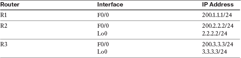
Configure the addresses shown in Table 8-1.
Table 8-1 IP Addressing
On R1:
R1(config)# interface FastEthernet0/0
R1(config-if)# ip address 200.1.1.1 255.255.255.0
R1(config-if)# no shutdown
On R2:
R2(config)# interface FastEthernet0/0
R2(config-if)# ip address 200.2.2.2 255.255.255.0
R2(config-if)# no shutdown
R2(config)# interface loopback0
R2(config-if)# ip address 2.2.2.2 255.255.255.0
On R3:
R3(config)# interface FastEthernet0/0
R3(config-if)# ip address 200.3.3.3 255.255.255.0
R3(config-if)# no shutdown
R3(config)# interface loopback0
R3(config-if)# ip address 3.3.3.3 255.255.255.0
OSPF can be configured in one of two different modes: router configuration mode or interface configuration mode. This task states that a network command cannot be used; therefore, the interface configuration mode is used to run OSPF Area 0 on the S1/2 interface of R1. When OSPF is configured directly on the interface, the IOS will automatically start the OSPF process for you.
Task 4
SW1 represents the Internet. Configure a static default route on each router pointing to the appropriate interface on SW1. If this configuration is performed correctly, these routers should be able to ping and have reachability to the F0/0 interfaces of all routers in this topology. The switch interface to which the routers are connected should have “.10” in the host portion of the IP address for that subnet.
Let’s configure SW1’s interfaces for these routers. Since in this lab SW1 represents the Internet, the IP addresses in the following configuration should be set as the default gateway on the routers.
On SW1:
SW1(config)# interface range FastEthernet0/1-3
SW1(config-if-range)# no switchport
SW1(config)# interface FastEthernet0/1
SW1(config-if)# ip address 200.1.1.10 255.255.255.0
SW1(config-if)# no shut
SW1(config)# interface FastEthernet0/2
SW1(config-if)# ip addr 200.2.2.10 255.255.255.0
SW1(config-if)# no shut
SW1(config)# interface f0/3
SW1(config-if)# ip addr 200.3.3.10 255.255.255.0
SW1(config-if)# no shut
Let’s not forget to enable ip routing; otherwise, the switch will not be able to route from one subnet to another:
SW1(config)# ip routing
Let’s configure the routers:
On R1:
R1(config)# ip route 0.0.0.0 0.0.0.0 200.1.1.10
On R3:
R3(config)# ip route 0.0.0.0 0.0.0.0 200.1.3.10
Now let’s verify the configuration:
On R1:
R1# ping 200.2.2.2
Type escape sequence to abort.
Sending 5, 100-byte ICMP Echos to 200.2.2.2, timeout is 2 seconds:
!!!!!
Success rate is 100 percent (5/5), round-trip min/avg/max = 1/2/4 ms
R1# ping 200.3.3.3
Type escape sequence to abort.
Sending 5, 100-byte ICMP Echos to 200.3.3.3, timeout is 2 seconds:
!!!!!
Success rate is 100 percent (5/5), round-trip min/avg/max = 1/2/4 ms
On R2:
R2# ping 200.3.3.3
Type escape sequence to abort.
Sending 5, 100-byte ICMP Echos to 200.3.3.3, timeout is 2 seconds:
!!!!!
Success rate is 100 percent (5/5), round-trip min/avg/max = 1/2/4 ms
Task 5
SW1 represents the Internet. Configure a static default route on each router pointing to the appropriate interface on SW1. If this configuration is performed correctly, these routers should be able to ping and have reachability to the F0/0 interfaces of all routers in this topology. The switch interface to which the routers are connected should have “.10” in the host portion of the IP address for that subnet.
Configure the dynamic multipoint virtual private network (DMVPN) based on the following policies:
![]() R1 should be the Next-Hop Resolution Protocol server (NHS), and R2 and R3 should be the spokes.
R1 should be the Next-Hop Resolution Protocol server (NHS), and R2 and R3 should be the spokes.
![]() R1 should not be configured with any static mappings.
R1 should not be configured with any static mappings.
![]() R2 and R3 should be configured in a point-to-point manner.
R2 and R3 should be configured in a point-to-point manner.
![]() The tunnel source of these routers should be based on their f0/0 interfaces.
The tunnel source of these routers should be based on their f0/0 interfaces.
![]() Provide multicast capability on the appropriate router(s).
Provide multicast capability on the appropriate router(s).
On R1:
R1(config)# interface tunnel 1
R1(config-if)# ip address 10.1.1.1 255.255.255.0
R1(config-if)# tunnel source FastEthernet0/0
R1(config-if)# tunnel mode gre multipoint
R1(config-if)# ip nhrp network-id 111
R1(config-if)# ip nhrp map multicast dynamic
On R2:
R2(config)# interface tunnel 1
R2(config-if)# ip address 10.1.1.2 255.255.255.0
R2(config-if)# tunnel source FastEthernet0/0
R2(config-if)# tunnel destination 200.1.1.1
R2(config-if)# ip nhrp network-id 222
R2(config-if)# ip nhrp nhs 10.1.1.1
R2(config-if)# ip nhrp map 10.1.1.1 200.1.1.1
Let’s verify the configuration:
On R2:
R2# ping 10.1.1.1
Type escape sequence to abort.
Sending 5, 100-byte ICMP Echos to 10.1.1.1, timeout is 2 seconds:
!!!!!
Success rate is 100 percent (5/5), round-trip min/avg/max = 1/2/4 ms
On R3:
R3(config)# interface tunnel 1
R3(config-if)# ip address 10.1.1.3 255.255.255.0
R3(config-if)# tunnel source FastEthernet0/0
R3(config-if)# tunnel destination 200.1.1.1
R3(config-if)# ip nhrp network-id 333
R3(config-if)# ip nhrp nhs 10.1.1.1
R3(config-if)# ip nhrp map 10.1.1.1 200.1.1.1
Pings will let us know if we have reachability
On R3:
R3# ping 10.1.1.1
Type escape sequence to abort.
Sending 5, 100-byte ICMP Echos to 10.1.1.1, timeout is 2 seconds:
!!!!!
Success rate is 100 percent (5/5), round-trip min/avg/max = 1/3/4 ms
R3# ping 10.1.1.2
Type escape sequence to abort.
Sending 5, 100-byte ICMP Echos to 10.1.1.2, timeout is 2 seconds:
!!!!!
Success rate is 100 percent (5/5), round-trip min/avg/max = 1/3/4 ms
Task 6
Configure OSPF Area 0 on the tunnel interfaces of R1, R2, and R3 as well as the loopback0 interfaces of R2 and R3. The loopback interfaces must be advertised with their correct mask. The OSPF router IDs of R2 and R3 should be configured to be 0.0.0.2 and 0.0.0.3, respectively. There should not be any designated router (DR) or backup designated router (BDR) on this segment.
On R1:
R1(config)# router ospf 1
R1(config-router)# network 10.1.1.1 0.0.0.0 area 0
On R2:
R2(config)# router ospf 1
R2(config-router)# router-id 0.0.0.2
R2(config-router)# network 2.2.2.2 0.0.0.0 area 0
R2(config-router)# network 10.1.1.2 0.0.0.0 area 0
On R5:
R5(config)# interface lo0
R5(config-if)# ip ospf network point-to-point
You should see the following console message:
%OSPF-5-ADJCHG: Process 1, Nbr 0.0.0.1 on Tunnel1 from LOADING to FULL,
Loading Done
On R3:
R3(config)# router ospf 1
R3(config-router)# router-id 0.0.0.3
R3(config-router)# network 3.3.3.3 0.0.0.0 area 0
R3(config-router)# network 10.1.1.3 0.0.0.0 area 0
R3(config)# interface loopback0
R3(config-if)# ip ospf network point-to-point
You should also see the following console messages:
%OSPF-5-ADJCHG: Process 1, Nbr 0.0.0.1 on Tunnel1 from LOADING to FULL,
Loading Done
%OSPF-5-ADJCHG: Process 1, Nbr 0.0.0.1 on Tunnel1 from LOADING to FULL,
Loading Done
%OSPF-5-ADJCHG: Process 1, Nbr 0.0.0.1 on Tunnel1 from LOADING to FULL,
Loading Done
It seems like the local router (R3) keeps reestablishing an OSPF adjacency with R1. Let’s see why.
Let’s look at the rules and conditions that must be met before two OSPF routers form an adjacency:
![]() Timers must match.
Timers must match.
![]() Area IDs must match.
Area IDs must match.
![]() The two routers must be on the same subnet.
The two routers must be on the same subnet.
![]() The authentication type and passwords must match.
The authentication type and passwords must match.
![]() The MTUs must match.
The MTUs must match.
Let’s verify these items.
On R1, you can see that the Tunnel 1 interface keeps on flapping: It establishes an OSPF adjacency with 0.0.0.2 and then drops the adjacency and forms an adjacency with 0.0.0.3, and then the cycle repeats. You cannot even access the console of R1 because of the messages. In order to have access to R1’s console, let’s shut down the f0/1 interface on SW1:
On SW1:
SW1(config)# interface FastEthernet0/1
SW1(config-if)# shutdown
Once the f0/1 interface is shut down, you can access the console. Let’s verify the information on the tunnel interface of R1:
On R1:
R1# show ip ospf interface tunnel 1 | inc Timer
Timer intervals configured, Hello 10, Dead 40, Wait 40, Retransmit 5
The tunnel interface is configured in a multipoint manner, but why are the hello and dead intervals set to 10 and 40 seconds, respectively?
Let’s check the network type:
R1# show ip ospf interface tunnel 1 | include Network
Internet Address 10.1.1.1/24, Area 0, Attached via Network Statement
Process ID 1, Router ID 0.0.0.1, Network Type POINT_TO_POINT, Cost: 1000
You can see the problem: OSPF does not read or process the “tunnel mode GRE multipoint.” OSPF sees a tunnel interface and assumes that it is a point-to-point tunnel; therefore, it sets the OSPF network type to point-to-point. Because you cannot have a DR/BDR (based on the task’s requirements), let’s change the network type to “point-to-multipoint” and then no shutdown the f0/1 interface on SW1 and test the adjacency again:
R1(config)# interface tunnel 1
R1(config-if)# ip ospf network point-to-multipoint
Let’s verify the neighbor adjacency on R1:
On R1:
R1# show ip ospf neighbor
Neighbor ID Pri State Dead Time Address Interface
0.0.0.4 0 FULL/ - 00:00:33 14.1.1.4 Serial1/4
Let’s see if the spoke routers have registered themselves with the hub router:
R1# show ip nhrp
Nothing in the NHRP table. There are many ways to fix this problem. One way is to configure the spoke routers to send a registration request every 5 seconds. Let’s test this:
On R2 and R3:
Rx(config)# interface tunnel 1
Rx(config-if)# ip nhrp registration timeout 5
Now let’s verify the configuration:
On R1:
R1# show ip nhrp
10.1.1.2/32 via 10.1.1.2
Tunnel1 created 00:01:01, expire 01:59:58
Type: dynamic, Flags: unique registered used
NBMA address: 200.2.2.2
10.1.1.3/32 via 10.1.1.3
Tunnel1 created 00:00:06, expire 01:59:58
Type: dynamic, Flags: unique registered used
NBMA address: 200.3.3.3
The spoke routers, R2 and R3, have successfully registered themselves with the hub router, R1. However, the routers have not formed an adjacency. Let’s verify the timers:
R1# show ip ospf interface tunnel 1 | include Timer
Timer intervals configured, Hello 30, Dead 120, Wait 120, Retransmit 5
On R2:
R2# show ip ospf interface tunnel 1 | include Timer
Timer intervals configured, Hello 10, Dead 40, Wait 40, Retransmit 5
On R3:
R3# show ip ospf interface tunnel 1 | include Timer
Timer intervals configured, Hello 10, Dead 40, Wait 40, Retransmit 5
You can see the problem: The timers do not match. Let’s configure the hello and dead intervals on R1’s tunnel interface to match R2 and R3:
On R1:
R1(config)# interface tunnel 1
R1(config-if)# ip ospf hello-interval 10
Note Once the preceding command is entered, you should see the following console messages:
%OSPF-5-ADJCHG: Process 1, Nbr 0.0.0.3 on Tunnel1 from LOADING to FULL,
Loading Done
%OSPF-5-ADJCHG: Process 1, Nbr 0.0.0.2 on Tunnel1 from LOADING to FULL,
Loading Done
However, we didn’t change the dead interval. Did the dead interval automatically adjust? Let’s verify:
R1# show ip ospf interface tunnel 1 | include Timer
Timer intervals configured, Hello 10, Dead 40, Wait 40, Retransmit 5
Yes, if the hello interval is changed, the dead interval will automatically be set to four times the hello interval.
Let’s verify the configuration:
On R3:
R3# show ip route ospf | begin Gate
Gateway of last resort is 200.3.3.10 to network 0.0.0.0
1.0.0.0/24 is subnetted, 1 subnets
O 1.1.1.0 [110/1001] via 10.1.1.1, 00:03:16, Tunnel1
2.0.0.0/24 is subnetted, 1 subnets
O 2.2.2.0 [110/2001] via 10.1.1.1, 00:03:06, Tunnel1
4.0.0.0/24 is subnetted, 1 subnets
O 4.4.4.0 [110/1782] via 10.1.1.1, 00:03:16, Tunnel1
5.0.0.0/24 is subnetted, 1 subnets
O 5.5.5.0 [110/1783] via 10.1.1.1, 00:03:16, Tunnel1
6.0.0.0/24 is subnetted, 1 subnets
O 6.6.6.0 [110/1783] via 10.1.1.1, 00:03:16, Tunnel1
10.0.0.0/8 is variably subnetted, 3 subnets, 2 masks
O 10.1.1.1/32 [110/1000] via 10.1.1.1, 00:03:16, Tunnel1
14.0.0.0/24 is subnetted, 1 subnets
O 14.1.1.0 [110/1781] via 10.1.1.1, 00:03:16, Tunnel1
100.0.0.0/24 is subnetted, 1 subnets
O 100.1.1.0 [110/1782] via 10.1.1.1, 00:03:16, Tunnel1
On R2:
R2# show ip route ospf | begin Gate
Gateway of last resort is 200.2.2.10 to network 0.0.0.0
1.0.0.0/24 is subnetted, 1 subnets
O 1.1.1.0 [110/1001] via 10.1.1.1, 00:03:41, Tunnel1
3.0.0.0/24 is subnetted, 1 subnets
O 3.3.3.0 [110/2001] via 10.1.1.1, 00:03:41, Tunnel1
4.0.0.0/24 is subnetted, 1 subnets
O 4.4.4.0 [110/1782] via 10.1.1.1, 00:03:41, Tunnel1
5.0.0.0/24 is subnetted, 1 subnets
O 5.5.5.0 [110/1783] via 10.1.1.1, 00:03:41, Tunnel1
6.0.0.0/24 is subnetted, 1 subnets
O 6.6.6.0 [110/1783] via 10.1.1.1, 00:03:41, Tunnel1
10.0.0.0/8 is variably subnetted, 3 subnets, 2 masks
O 10.1.1.1/32 [110/1000] via 10.1.1.1, 00:03:41, Tunnel1
14.0.0.0/24 is subnetted, 1 subnets
O 14.1.1.0 [110/1781] via 10.1.1.1, 00:03:41, Tunnel1
100.0.0.0/24 is subnetted, 1 subnets
O 100.1.1.0 [110/1782] via 10.1.1.1, 00:03:41, Tunnel1
Erase the startup configuration and reload the routers before proceeding to the next lab.
Lab 8-2: OSPF Broadcast Networks
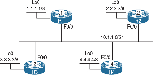
Figure 8-2 OSPF Broadcast Networks
Task 1
Configure OSPF Area 0 on the f0/0 and lo0 interfaces in Figure 8-2. Configure the loopback interfaces such that they are advertised with their correct mask. You should configure 0.0.0.1, 0.0.0.2, 0.0.0.3, and 0.0.0.4 with the router IDs of R1, R2, R3, and R4, respectively.
On R1:
R1(config)# router ospf 1
R1(config-router)# router-id 0.0.0.1
R1(config-router)# network 10.1.1.1 0.0.0.0 area 0
R1(config-router)# network 1.1.1.1 0.0.0.0 area 0
R1(config-router)# interface loopback0
R1(config-if)# ip ospf network point-to-point
On R2:
R2(config)# router ospf 1
R2(config-router)# router-id 0.0.0.2
R2(config-router)# network 10.1.1.2 0.0.0.0 area 0
R2(config-router)# network 2.2.2.2 0.0.0.0 area 0
R2(config-router)# interface loopback0
R2(config-if)# ip ospf network point-to-point
On R3:
R3(config)# router ospf 1
R3(config-router)# router-id 0.0.0.3
R3(config-router)# network 10.1.1.3 0.0.0.0 area 0
R3(config-router)# network 3.3.3.3 0.0.0.0 area 0
R3(config-router)# interface loopback0
R3(config-if)# ip ospf network point-to-point
On R4:
R4(config)# router ospf 1
R4(config-router)# router-id 0.0.0.4
R4(config-router)# network 10.1.1.4 0.0.0.0 area 0
R4(config-router)# network 4.4.4.4 0.0.0.0 area 0
R4(config-router)# interface loopback0
R4(config-if)# ip ospf network point-to-point
Let’s verify the configuration:
On R1:
R1# show ip route ospf | begin Gate
Gateway of last resort is not set
O 2.0.0.0/8 [110/2] via 10.1.1.2, 00:00:20, FastEthernet0/0
O 3.0.0.0/8 [110/2] via 10.1.1.3, 00:00:20, FastEthernet0/0
O 4.0.0.0/8 [110/2] via 10.1.1.4, 00:00:30, FastEthernet0/0
R1# show ip ospf database
OSPF router with ID (0.0.0.1) (Process ID 1)
router Link States (Area 0)
Link ID ADV router Age Seq# Checksum Link count
0.0.0.1 0.0.0.1 90 0x80000004 0x00D02E 2
0.0.0.2 0.0.0.2 91 0x80000004 0x00E119 2
0.0.0.3 0.0.0.3 91 0x80000004 0x00F204 2
0.0.0.4 0.0.0.4 91 0x80000004 0x0004EE 2
Net Link States (Area 0)
Link ID ADV router Age Seq# Checksum
10.1.1.4 0.0.0.4 90 0x80000001 0x0072A1
R1# show ip ospf database network
OSPF router with ID (0.0.0.1) (Process ID 1)
Net Link States (Area 0)
Routing Bit Set on this LSA in topology Base with MTID 0
LS age: 189
Options: (No TOS-capability, DC)
LS Type: network Links
Link State ID: 10.1.1.4 (address of Designated Router)
Advertising Router: 0.0.0.4
LS Seq Number: 80000001
Checksum: 0x72A1
Length: 40
network Mask: /24
Attached Router: 0.0.0.4
Attached Router: 0.0.0.1
Attached Router: 0.0.0.2
Attached Router: 0.0.0.3
You can see that it’s the DR that floods Type-2 LSAs, and on this segment R4 is the DR with an IP address of 10.1.1.4/24, which means 10.1.1.0/24 is the network address of this segment. This segment will not be advertised by the other routers; only the DR is responsible for this. Network LSAs or Type-2 LSAs also reveal the router IDs of the other routers that are attached to this broadcast multi-access network.
R1# show ip ospf neighbor
Neighbor ID Pri State Dead Time Address Interface
0.0.0.2 1 2WAY/DROTHER 00:00:32 10.1.1.2 FastEthernet0/0
0.0.0.3 1 FULL/BDR 00:00:37 10.1.1.3 FastEthernet0/0
0.0.0.4 1 FULL/DR 00:00:37 10.1.1.4 FastEthernet0/0
Based on the preceding output, you can see that the local router is in the 2WAY state with R2 and in the FULL state with the DR and BDR. Let’s check the routing table of R1:
R1# show ip route ospf | begin Gate
Gateway of last resort is not set
O 2.0.0.0/8 [110/2] via 10.1.1.2, 00:13:30, FastEthernet0/0
O 3.0.0.0/8 [110/2] via 10.1.1.3, 00:13:30, FastEthernet0/0
O 4.0.0.0/8 [110/2] via 10.1.1.4, 00:13:40, FastEthernet0/0
You can see the next hop to reach any network is the router that originated that particular network. Let’s see how often these routers exchange hellos:
R1# show ip ospf interface FastEthernet0/0 | include Timer
Timer intervals configured, Hello 10, Dead 40, Wait 40, Retransmit 5
Let’s see the destination address of OSPF hello messages on OSPF broadcast network types:
R1# debug ip ospf hello
OSPF hello debugging is on
OSPF-1 HELLO Fa0/0: Send hello to 224.0.0.5 area 0 from 10.1.1.1
R1# undebug all
All possible debugging has been turned off
Let’s identify the major points of an OSPF broadcast network type:
![]() Ethernet networks default to OSPF broadcast network types.
Ethernet networks default to OSPF broadcast network types.
![]() The timers are 10/40, meaning that the hello interval is 10 seconds and the dead interval is set to 40 seconds.
The timers are 10/40, meaning that the hello interval is 10 seconds and the dead interval is set to 40 seconds.
![]() The next hop does not change. In the output of the preceding show ip route ospf command, you can see that the next-hop IP address is the IP address of the f0/0 interface of the router that originated the route.
The next hop does not change. In the output of the preceding show ip route ospf command, you can see that the next-hop IP address is the IP address of the f0/0 interface of the router that originated the route.
![]() DR and BDR election will take place in broadcast multi-access networks.
DR and BDR election will take place in broadcast multi-access networks.
![]() With broadcast network types, the hellos are sent to the multicast destination of 224.0.0.5.
With broadcast network types, the hellos are sent to the multicast destination of 224.0.0.5.
Task 2
Reload the routers and configure them by copying and pasting the initial config file called Lab8-2_OSPF Broadcast Network_Task2.txt.
Figure 8-3 introduces the topology we will use to explore OSPF functionality via a non-broadcast multi-access network using DMVPN.

Figure 8-3 OSPF DMVPN Topology
Configure OSPF on the tunnel and loopback0 interfaces of all routers based on the following policies:
![]() R1 is the hub, and R2, R3, and R4 are configured as the spokes. Do not change the topology. All routers are configured in a multipoint manner.
R1 is the hub, and R2, R3, and R4 are configured as the spokes. Do not change the topology. All routers are configured in a multipoint manner.
![]() Configure the tunnel interfaces of all routers to be the OSPF broadcast network type.
Configure the tunnel interfaces of all routers to be the OSPF broadcast network type.
![]() The loopback interfaces should be advertised with their correct mask.
The loopback interfaces should be advertised with their correct mask.
![]() Configure the router IDs of 0.0.0.1, 0.0.0.2, 0.0.0.3, and 0.0.0.4 for R1, R2, R3, and R4, respectively.
Configure the router IDs of 0.0.0.1, 0.0.0.2, 0.0.0.3, and 0.0.0.4 for R1, R2, R3, and R4, respectively.
On All Routers:
Rx(config-router)# interface loopback0
Rx(config-if)# ip ospf network point-to-point
Rx(config)# interface tunnel 1234
Rx(config-if)# ip ospf network broadcast
On R1:
R1(config)# router ospf 1
R1(config-router)# router-id 0.0.0.1
R1(config-router)# network 10.1.1.1 0.0.0.0 area 0
R1(config-router)# network 1.1.1.1 0.0.0.0 area 0
On R2:
R2(config)# router ospf 1
R2(config-router)# router-id 0.0.0.2
R2(config-router)# network 2.2.2.2 0.0.0.0 area 0
R2(config-router)# network 10.1.1.2 0.0.0.0 area 0
On R3:
R3(config)# router ospf 1
R3(config-router)# router-id 0.0.0.3
R3(config-router)# network 3.3.3.3 0.0.0.0 area 0
R3(config-router)# network 10.1.1.3 0.0.0.0 area 0
On R4:
R4(config)# router ospf 1
R4(config-router)# router-id 0.0.0.4
R4(config-router)# network 4.4.4.4 0.0.0.0 area 0
R4(config-router)# network 10.1.1.4 0.0.0.0 area 0
Let’s verify the configuration:
On R1:
R1# show ip ospf neighbor
You can see that the routers did not establish an OSPF adjacency. We know that in OSPF broadcast network types, the hellos are sent to a destination multicast address of 224.0.0.5, so let’s check and see if our network allows multicast traffic through:
On R1:
R1# show run interface tunnel 1234 | begin interface
interface Tunnel1234
ip address 10.1.1.1 255.255.255.0
no ip redirects
ip nhrp map 10.1.1.4 192.1.4.4
ip nhrp map 10.1.1.3 192.1.3.3
ip nhrp map 10.1.1.2 192.1.2.2
ip nhrp network-id 111
ip ospf network broadcast
tunnel source FastEthernet0/0
tunnel mode gre multipoint
end
Based on the preceding output, you can see that multicast is not mapped. Let’s check R2:
On R2:
R2# show run interface tunnel 1234 | begin interface
interface Tunnel1234
ip address 10.1.1.2 255.255.255.0
no ip redirects
ip nhrp map 10.1.1.1 192.1.1.1
ip nhrp network-id 222
ip ospf network broadcast
tunnel source FastEthernet0/0
tunnel mode gre multipoint
end
R2 is configured the same. Let’s map multicast on R1 and R2 and see the result before we move on to the other routers:
On R2:
R2(config)# interface tunnel 1234
R2(config-if)# ip nhrp map multicast 192.1.1.1
On R1:
R1(config)# interface tunnel 1234
R1(config-if)# ip nhrp map multicast 192.1.2.2
If both ends are not configured to map multicast for each other’s tunnel IP addresses, the OSPF adjacency will be established and torn down, and you will get the following console message:
%OSPF-5-ADJCHG: Process 1, Nbr 0.0.0.2 on Tunnel1234 from LOADING to FULL,
Loading Done
%OSPF-5-ADJCHG: Process 1, Nbr 0.0.0.2 on Tunnel1234 from FULL to DOWN,
neighbor Down: Dead timer expired
Let’s verify the adjacency and see if these two routers are exchanging routes:
On R1:
R1# show ip ospf neighbor
Neighbor ID Pri State Dead Time Address Interface
0.0.0.2 1 FULL/DR 00:00:37 10.1.1.2 Tunnel1234
R1# show ip route ospf | be Gate
Gateway of last resort is not set
O 2.0.0.0/8 [110/1001] via 10.1.1.2, 00:01:08, Tunnel1234
Let’s configure the other spokes to map multicast traffic:
On R1:
R1(config)# interface tunnel 1234
R1(config-if)# ip nhrp map multicast 192.1.3.3
R1(config-if)# ip nhrp map multicast 192.1.4.4
On R3:
R3(config)# interface tunnel 1234
R3(config-if)# ip nhrp map multicast 192.1.1.1
On R4:
R4(config)# interface tunnel 1234
R4(config-if)# ip nhrp map multicast 192.1.1.1
Let’s verify the configuration:
On R1:
R1# show ip ospf neighbor
Neighbor ID Pri State Dead Time Address Interface
0.0.0.2 1 FULL/DROTHER 00:00:35 10.1.1.2 Tunnel1234
0.0.0.3 1 FULL/DROTHER 00:00:30 10.1.1.3 Tunnel1234
0.0.0.4 1 FULL/DR 00:00:31 10.1.1.4 Tunnel1234
You can see that R4, which happens to be one of the spokes, is the DR. You should always configure the hub router as the DR, so let’s configure this and verify:
On R2, R3, and R4:
Rx(config)# interface tunnel 1234
Rx(config-if)# ip ospf priority 0
On All Routers:
Rx# Clear ip ospf process
Reset ALL OSPF processes? [no]: Yes
On R1:
R1# show ip ospf neighbor
neighbor ID Pri State Dead Time Address Interface
0.0.0.2 0 FULL/DROTHER 00:00:31 10.1.1.2 Tunnel1234
0.0.0.3 0 FULL/DROTHER 00:00:32 10.1.1.3 Tunnel1234
0.0.0.4 0 FULL/DROTHER 00:00:32 10.1.1.4 Tunnel1234
R1# show ip route ospf | begin Gate
Gateway of last resort is not set
O 2.0.0.0/8 [110/1001] via 10.1.1.2, 00:01:58, Tunnel1234
O 3.0.0.0/8 [110/1001] via 10.1.1.3, 00:01:58, Tunnel1234
O 4.0.0.0/8 [110/1001] via 10.1.1.4, 00:01:58, Tunnel1234
Note We know that on broadcast network types, the next-hop IP address is set based on the originating router. From R1’s perspective, this is not a problem, but let’s check R2 and the other spokes:
On R2:
R2# show ip route ospf | begin Gate
Gateway of last resort is not set
O 1.0.0.0/8 [110/1001] via 10.1.1.1, 00:03:18, Tunnel1234
O 3.0.0.0/8 [110/1001] via 10.1.1.3, 00:03:08, Tunnel1234
O 4.0.0.0/8 [110/1001] via 10.1.1.4, 00:03:18, Tunnel1234
Does R2 have reachability to the advertised networks? Let’s verify:
R2# ping 1.1.1.1
Type escape sequence to abort.
Sending 5, 100-byte ICMP Echos to 1.1.1.1, timeout is 2 seconds:
!!!!!
Success rate is 100 percent (5/5), round-trip min/avg/max = 1/2/4 ms
R2# ping 3.3.3.3
Type escape sequence to abort.
Sending 5, 100-byte ICMP Echos to 3.3.3.3, timeout is 2 seconds:
.....
Success rate is 0 percent (0/5)
R2# ping 4.4.4.4
Type escape sequence to abort.
Sending 5, 100-byte ICMP Echos to 4.4.4.4, timeout is 2 seconds:
.....
Success rate is 0 percent (0/5)
R2 has reachability to the 1.1.1.1 prefix only. Does R2 have reachability to the next-hop IP address of the other spoke routers? Let’s verify:
R2# ping 10.1.1.3
Type escape sequence to abort.
Sending 5, 100-byte ICMP Echos to 10.1.1.3, timeout is 2 seconds:
.....
Success rate is 0 percent (0/5)
R2# ping 10.1.1.4
Type escape sequence to abort.
Sending 5, 100-byte ICMP Echos to 10.1.1.4, timeout is 2 seconds:
.....
Success rate is 0 percent (0/5)
No, it doesn’t. If the network is configured in a point-to-point manner, the routers have unicast, multicast, and/or broadcast capability. In a point-to-point network, because there can only be another node/router on the other end of the link/tunnel, as long as the destination network is in the routing table, you should be able to reach the destination.
On the other hand, if the network is configured as multipoint, you have unicast reachability, but broadcast/multicast capability is only available if it’s provided.
Because in a multipoint network there can potentially be more than one router on the other end of the tunnel, the local router must have a mapping to the next-hop IP address(es). Otherwise, Network Layer Reachability Information (NLRI) cannot be achieved.
Because the spoke routers don’t have mapping for each other’s tunnel IP address, they cannot reach the advertised networks. Let’s provide this reachability and verify:
On R2:
R2(config)# interface tunnel 1234
R2(config-if)# ip nhrp map 10.1.1.3 192.1.3.3
On R3:
R3(config)# interface tunnel 1234
R3(config-if)# ip nhrp map 10.1.1.2 192.1.2.2
Let’s verify the configuration:
On R3:
R3# ping 10.1.1.2
Type escape sequence to abort.
Sending 5, 100-byte ICMP Echos to 10.1.1.2, timeout is 2 seconds:
!!!!!
Success rate is 100 percent (5/5), round-trip min/avg/max = 1/2/4 ms
This is great. Let’s configure full mesh logical mapping between the spoke routers:
On R2:
R2(config)# interface tunnel 1234
R2(config-if)# ip nhrp map 10.1.1.4 192.1.4.4
On R3:
R3(config)# interface tunnel 1234
R3(config-if)# ip nhrp map 10.1.1.4 192.1.4.4
On R4:
R4(config)# interface tunnel 1234
R4(config-if)# ip nhrp map 10.1.1.2 192.1.2.2
R4(config-if)# ip nhrp map 10.1.1.3 192.1.3.3
Let’s verify the mappings:
On R2:
R2# show ip nhrp
10.1.1.1/32 via 10.1.1.1
Tunnel1234 created 00:50:36, never expire
Type: static, Flags: used
NBMA address: 192.1.1.1
10.1.1.3/32 via 10.1.1.3
Tunnel1234 created 00:04:57, never expire
Type: static, Flags:
NBMA address: 192.1.1.1
10.1.1.4/32 via 10.1.1.4
Tunnel1234 created 00:01:41, never expire
Type: static, Flags:
NBMA address: 192.1.1.1
On R3:
R3# show ip nhrp
10.1.1.1/32 via 10.1.1.1
Tunnel1234 created 00:50:50, never expire
Type: static, Flags: used
NBMA address: 192.1.1.1
10.1.1.2/32 via 10.1.1.2
Tunnel1234 created 00:05:11, never expire
Type: static, Flags:
NBMA address: 192.1.1.1
10.1.1.4/32 via 10.1.1.4
Tunnel1234 created 00:02:28, never expire
Type: static, Flags:
NBMA address: 192.1.1.1
On R4:
R4# show ip nhrp
10.1.1.1/32 via 10.1.1.1
Tunnel1234 created 00:50:54, never expire
Type: static, Flags: used
NBMA address: 192.1.1.1
10.1.1.2/32 via 10.1.1.2
Tunnel1234 created 00:01:33, never expire
Type: static, Flags:
NBMA address: 192.1.1.1
10.1.1.3/32 via 10.1.1.3
Tunnel1234 created 00:01:25, never expire
Type: static, Flags:
NBMA address: 192.1.1.1
Let’s test the configuration:
On R2:
R2# ping 3.3.3.3
Type escape sequence to abort.
Sending 5, 100-byte ICMP Echos to 3.3.3.3, timeout is 2 seconds:
!!!!!
Success rate is 100 percent (5/5), round-trip min/avg/max = 1/3/4 ms
R2# ping 4.4.4.4
Type escape sequence to abort.
Sending 5, 100-byte ICMP Echos to 4.4.4.4, timeout is 2 seconds:
!!!!!
Success rate is 100 percent (5/5), round-trip min/avg/max = 1/2/4 ms
R2# traceroute 3.3.3.3 numeric
Type escape sequence to abort.
Tracing the route to 3.3.3.3
VRF info: (vrf in name/id, vrf out name/id)
1 10.1.1.3 4 msec * 0 msec
On R3:
R3# ping 4.4.4.4
Type escape sequence to abort.
Sending 5, 100-byte ICMP Echos to 4.4.4.4, timeout is 2 seconds:
!!!!!
Success rate is 100 percent (5/5), round-trip min/avg/max = 1/2/4 ms
In broadcast network types, the next-hop IP address is not changed. If the network is Non-Broadcast Multi-Access (NBMA) in nature and it’s configured in a multipoint manner, you have to remember the following:
![]() Multicast capability must be provided.
Multicast capability must be provided.
![]() Spokes must have mapping to the next-hop IP address to have reachability to the networks that other spokes are advertising.
Spokes must have mapping to the next-hop IP address to have reachability to the networks that other spokes are advertising.
Erase the startup configuration of the routers as well as the config.text and vlan.dat files of the switches and reload them before proceeding to the next lab.
Lab 8-3: Non-Broadcast Networks
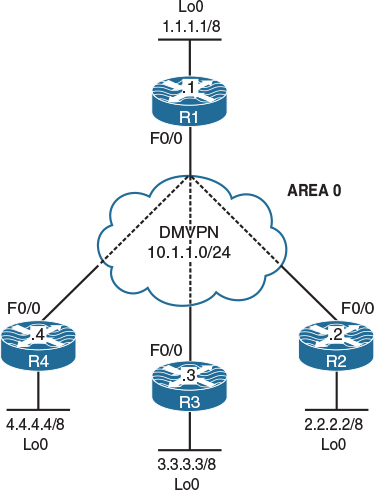
Figure 8-4 OSPF Non-Broadcast Networks
The DMVPN is configured in Phase 2 using static maps. R1 (the hub router) is configured with two static maps—one for each spoke. Routers R2 and R3 are configured with a single map for the hub.
Task 1
Configure OSPF Area 0 on the tunnel and the loopback interfaces of all routers in the topology shown in Figure 8-4. You should configure the tunnel interfaces as the OSPF non-broadcast network type. Use the following list for the router IDs:
R1: 0.0.0.1
R2: 0.0.0.2
R3: 0.0.0.3
R4: 0.0.0.4
On All Routers:
Rx(config)# interface tunnel 1234
Rx(config-if)# ip ospf network non-broadcast
On R1:
R1(config)# router ospf 1
R1(config-router)# router-id 0.0.0.1
R1(config-router)# network 10.1.1.1 0.0.0.0 area 0
R1(config-router)# network 1.1.1.1 0.0.0.0 area 0
On R2:
R2(config)# router ospf 1
R2(config-router)# router-id 0.0.0.2
R2(config-router)# network 10.1.1.2 0.0.0.0 area 0
R2(config-router)# network 2.2.2.2 0.0.0.0 area 0
On R3:
R3(config)# router ospf 1
R3(config-router)# router-id 0.0.0.3
R3(config-router)# network 3.3.3.3 0.0.0.0 area 0
R3(config-router)# network 10.1.1.3 0.0.0.0 area 0
On R4:
R4(config)# router ospf 1
R4(config-router)# router-id 0.0.0.4
R4(config-router)# network 4.4.4.4 0.0.0.0 area 0
R4(config-router)# network 10.1.1.4 0.0.0.0 area 0
Let’s verify the configuration:
On R1:
R1# show ip ospf neighbor
R1# show ip ospf interface brief
Interface PID Area IP Address/Mask Cost State Nbrs F/C
Lo0 1 0 1.1.1.1/8 1 LOOP 0/0
Tu1234 1 0 10.1.1.1/24 1000 DR 0/0
Let’s check OSPF’s configuration on the Tunnel 1234 interface:
R1# show ip ospf interface tunnel 1234
Tunnel1234 is up, line protocol is up
Internet Address 10.1.1.1/24, Area 0, Attached via network Statement
Process ID 1, router ID 0.0.0.1, network Type NON_BROADCAST, Cost: 1000
Topology-MTID Cost Disabled Shutdown Topology Name
0 1000 no no Base
Transmit Delay is 1 sec, State DR, Priority 1
Designated router (ID) 0.0.0.1, Interface address 10.1.1.1
No backup designated router on this network
Timer intervals configured, Hello 30, Dead 120, Wait 120, Retransmit 5
oob-resync timeout 120
(The rest of the output is omitted for brevity)
You can see that the network type is set to NON_BROADCAST, which means that one way to get the local router to establish an adjacency with another OSPF-speaking router is to use the neighbor command and change the multicast destination of 224.0.0.5 to unicast destinations of 10.1.1.2, 10.1.1.3, and 10.1.1.4. Thus, as you can see, the rules did not change at all; the same rules apply to all NBMA networks.
Let’s configure the neighbor commands on the routers:
On R1:
R1(config)# router ospf 1
R1(config-router)# neighbor 10.1.1.2
R1(config-router)# neighbor 10.1.1.3
R1(config-router)# neighbor 10.1.1.4
You should see the following console messages stating that the adjacencies are established with the OSPF 0.0.0.2, 0.0.0.3, and 0.0.0.4 neighbors:
%OSPF-5-ADJCHG: Process 1, Nbr 0.0.0.2 on Tunnel1234 from LOADING to FULL,
Loading Done
%OSPF-5-ADJCHG: Process 1, Nbr 0.0.0.3 on Tunnel1234 from LOADING to FULL,
Loading Done
%OSPF-5-ADJCHG: Process 1, Nbr 0.0.0.4 on Tunnel1234 from LOADING to FULL,
Loading Done
This worked, but let’s review some important points about OSPF non-broadcast networks:
![]() The neighbor command must be used because non-broadcast network types don’t have multicast capability.
The neighbor command must be used because non-broadcast network types don’t have multicast capability.
![]() The hello intervals are 30 seconds, and the dead interval is set to 120 seconds.
The hello intervals are 30 seconds, and the dead interval is set to 120 seconds.
![]() DR election is required.
DR election is required.
![]() In this network type, the next-hop IP address is based on the router that originated the route.
In this network type, the next-hop IP address is based on the router that originated the route.
Let’s go through every item and verify it.
If the routers don’t have multicast capability, then the neighbor command must be configured. In hub-and-spoke networks, the hub must be the DR, and the spokes are configured with a priority of 0 so that they don’t participate in the DR/BDR election.
On R2:
R2# show ip ospf interface tunnel 1234 | include Priority
Transmit Delay is 1 sec, State WAITING, Priority 1
On R3:
R3# show ip ospf interface tunnel 1234 | include Priority
Transmit Delay is 1 sec, State BDR, Priority 1
On R4:
R4# show ip ospf interface tunnel 1234 | include Priority
Transmit Delay is 1 sec, State BDR, Priority 1
Let’s configure the priority of the spoke routers as 0 and clear the OSPF process to implement the changes:
On R2, R3, and R4:
Rx(config)# interface tunnel 1234
Rx(config-if)# ip ospf priority 0
Rx# Clear ip ospf process
Reset ALL OSPF processes? [no]: Yes
Let’s verify the configuration:
On R1:
R1# show ip ospf neighbor
neighbor ID Pri State Dead Time Address Interface
0.0.0.2 0 FULL/DROTHER 00:01:46 10.1.1.2 Tunnel123
0.0.0.3 0 FULL/DROTHER 00:01:46 10.1.1.3 Tunnel1234
0.0.0.4 0 FULL/DROTHER 00:01:46 10.1.1.4 Tunnel1234
On All Routers:
On R1:
R1# show ip route ospf | begin Gate
Gateway of last resort is not set
2.0.0.0/32 is subnetted, 1 subnets
O 2.2.2.2 [110/1001] via 10.1.1.2, 00:03:13, Tunnel1234
3.0.0.0/32 is subnetted, 1 subnets
O 3.3.3.3 [110/1001] via 10.1.1.3, 00:03:13, Tunnel1234
4.0.0.0/32 is subnetted, 1 subnets
O 4.4.4.4 [110/1001] via 10.1.1.4, 00:03:13, Tunnel1234
Let’s check the routing table of the spokes:
On R2:
R2# show ip route ospf | begin Gate
Gateway of last resort is not set
1.0.0.0/32 is subnetted, 1 subnets
O 1.1.1.1 [110/1001] via 10.1.1.1, 00:04:16, Tunnel1234
3.0.0.0/32 is subnetted, 1 subnets
O 3.3.3.3 [110/1001] via 10.1.1.3, 00:04:06, Tunnel1234
4.0.0.0/32 is subnetted, 1 subnets
O 4.4.4.4 [110/1001] via 10.1.1.4, 00:04:06, Tunnel1234
On R3:
R3# show ip route ospf | begin Gate
Gateway of last resort is not set
1.0.0.0/32 is subnetted, 1 subnets
O 1.1.1.1 [110/1001] via 10.1.1.1, 00:05:03, Tunnel1234
2.0.0.0/32 is subnetted, 1 subnets
O 2.2.2.2 [110/1001] via 10.1.1.2, 00:05:03, Tunnel1234
4.0.0.0/32 is subnetted, 1 subnets
O 4.4.4.4 [110/1001] via 10.1.1.4, 00:04:53, Tunnel1234
On R4:
R4# show ip route ospf | begin Gate
Gateway of last resort is not set
1.0.0.0/32 is subnetted, 1 subnets
O 1.1.1.1 [110/1001] via 10.1.1.1, 00:05:12, Tunnel1234
2.0.0.0/32 is subnetted, 1 subnets
O 2.2.2.2 [110/1001] via 10.1.1.2, 00:05:12, Tunnel1234
3.0.0.0/32 is subnetted, 1 subnets
O 3.3.3.3 [110/1001] via 10.1.1.3, 00:05:02, Tunnel1234
As you can see, in OSPF non-broadcast networks, the next hop is based on the IP address of the router that originated the route. Do we have reachability to these addresses? Let’s verify:
R4# ping 10.1.1.1
Type escape sequence to abort.
Sending 5, 100-byte ICMP Echos to 10.1.1.1, timeout is 2 seconds:
!!!!!
Success rate is 100 percent (5/5), round-trip min/avg/max = 1/3/4 ms
R4# ping 10.1.1.2
Type escape sequence to abort.
Sending 5, 100-byte ICMP Echos to 10.1.1.2, timeout is 2 seconds:
.....
Success rate is 0 percent (0/5)
R4# ping 10.1.1.3
Type escape sequence to abort.
Sending 5, 100-byte ICMP Echos to 10.1.1.3, timeout is 2 seconds:
.....
Success rate is 0 percent (0/5)
As you can see, the spokes do not have reachability to the routes that are advertised by the other spokes. Let’s check their NHRP mapping (does that remind you of Frame Relay?):
R4# show ip nhrp
10.1.1.1/32 via 10.1.1.1
Tunnel1234 created 01:13:32, never expire
Type: static, Flags: used
NBMA address: 192.1.1.1
The only mapping is for the hub router, and that’s why the ping to the 1.1.1.1 prefix was successful. On R4, we should configure a mapping for R2 and another one for R3, and for the return traffic, a mapping from R2 and R3 to R4 is required. Let’s configure and verify:
On R4:
R4(config)# interface tunnel 1234
R4(config-if)# ip nhrp map 10.1.1.2 192.1.1.1
R4(config-if)# ip nhrp map 10.1.1.3 192.1.1.1
Note R4 is mapping the next-hop IP address (the tunnel IP address) to the NBMA IP address of the hub, so the topology does not change.
R4# show ip nhrp
10.1.1.1/32 via 10.1.1.1
Tunnel1234 created 00:48:05, never expire
Type: static, Flags: used
NBMA address: 192.1.1.1
10.1.1.2/32 via 10.1.1.2
Tunnel1234 created 00:01:34, never expire
Type: static, Flags:
NBMA address: 192.1.1.1
10.1.1.3/32 via 10.1.1.3
Tunnel1234 created 00:01:27, never expire
Type: static, Flags:
NBMA address: 192.1.1.1
On R2:
R2(config)# interface tunnel 1234
R2(config-if)# ip nhrp map 10.1.1.3 192.1.1.1
R2(config-if)# ip nhrp map 10.1.1.4 192.1.1.1
Let’s verify the configuration:
R2# show ip nhrp
10.1.1.1/32 via 10.1.1.1
Tunnel1234 created 00:50:07, never expire
Type: static, Flags: used
NBMA address: 192.1.1.1
10.1.1.3/32 via 10.1.1.3
Tunnel1234 created 00:00:31, never expire
Type: static, Flags:
NBMA address: 192.1.1.1
10.1.1.4/32 via 10.1.1.4
Tunnel1234 created 00:00:24, never expire
Type: static, Flags:
NBMA address: 192.1.1.1
On R3:
R3(config)# interface tunnel 1234
R3(config-if)# ip nhrp map 10.1.1.2 192.1.1.1
R3(config-if)# ip nhrp map 10.1.1.4 192.1.1.1
Another excellent verification step is to look at the show ip nhrp output below.
R3# show ip nhrp
10.1.1.1/32 via 10.1.1.1
Tunnel1234 created 00:51:19, never expire
Type: static, Flags: used
NBMA address: 192.1.1.1
10.1.1.2/32 via 10.1.1.2
Tunnel1234 created 00:00:28, never expire
Type: static, Flags:
NBMA address: 192.1.1.1
10.1.1.4/32 via 10.1.1.4
Tunnel1234 created 00:00:21, never expire
Type: static, Flags:
NBMA address: 192.1.1.1
Let’s verify the routing table and reachability on the spoke routers:
On R2:
R2# show ip route ospf | begin Gate
Gateway of last resort is not set
1.0.0.0/32 is subnetted, 1 subnets
O 1.1.1.1 [110/1001] via 10.1.1.1, 00:22:19, Tunnel1234
3.0.0.0/32 is subnetted, 1 subnets
O 3.3.3.3 [110/1001] via 10.1.1.3, 00:22:09, Tunnel1234
4.0.0.0/32 is subnetted, 1 subnets
O 4.4.4.4 [110/1001] via 10.1.1.4, 00:22:09, Tunnel1234
R2# ping 1.1.1.1
Type escape sequence to abort.
Sending 5, 100-byte ICMP Echos to 1.1.1.1, timeout is 2 seconds:
!!!!!
Success rate is 100 percent (5/5), round-trip min/avg/max = 1/2/4 ms
R2# ping 3.3.3.3
Type escape sequence to abort.
Sending 5, 100-byte ICMP Echos to 3.3.3.3, timeout is 2 seconds:
!!!!!
Success rate is 100 percent (5/5), round-trip min/avg/max = 1/2/4 ms
R2# ping 4.4.4.4
Type escape sequence to abort.
Sending 5, 100-byte ICMP Echos to 4.4.4.4, timeout is 2 seconds:
!!!!!
Success rate is 100 percent (5/5), round-trip min/avg/max = 1/2/4 ms
On R3:
R3# show ip route ospf | began Gate
Gateway of last resort is not set
1.0.0.0/32 is subnetted, 1 subnets
O 1.1.1.1 [110/1001] via 10.1.1.1, 00:32:39, Tunnel1234
2.0.0.0/32 is subnetted, 1 subnets
O 2.2.2.2 [110/1001] via 10.1.1.2, 00:32:39, Tunnel1234
4.0.0.0/32 is subnetted, 1 subnets
O 4.4.4.4 [110/1001] via 10.1.1.4, 00:32:29, Tunnel1234
R3# ping 10.1.1.1
Type escape sequence to abort.
Sending 5, 100-byte ICMP Echos to 10.1.1.1, timeout is 2 seconds:
!!!!!
Success rate is 100 percent (5/5), round-trip min/avg/max = 1/2/4 ms
R3# ping 2.2.2.2
Type escape sequence to abort.
Sending 5, 100-byte ICMP Echos to 2.2.2.2, timeout is 2 seconds:
!!!!!
Success rate is 100 percent (5/5), round-trip min/avg/max = 1/3/4 ms
R3# ping 4.4.4.4
Type escape sequence to abort.
Sending 5, 100-byte ICMP Echos to 4.4.4.4, timeout is 2 seconds:
!!!!!
Success rate is 100 percent (5/5), round-trip min/avg/max = 1/3/4 ms
On R4:
R4# show ip route ospf | begin Gate
Gateway of last resort is not set
1.0.0.0/32 is subnetted, 1 subnets
O 1.1.1.1 [110/1001] via 10.1.1.1, 00:33:16, Tunnel1234
2.0.0.0/32 is subnetted, 1 subnets
O 2.2.2.2 [110/1001] via 10.1.1.2, 00:33:16, Tunnel1234
3.0.0.0/32 is subnetted, 1 subnets
O 3.3.3.3 [110/1001] via 10.1.1.3, 00:33:06, Tunnel1234
R4# ping 1.1.1.1
Type escape sequence to abort.
Sending 5, 100-byte ICMP Echos to 1.1.1.1, timeout is 2 seconds:
!!!!!
Success rate is 100 percent (5/5), round-trip min/avg/max = 1/3/4 ms
R4# ping 2.2.2.2
Type escape sequence to abort.
Sending 5, 100-byte ICMP Echos to 2.2.2.2, timeout is 2 seconds:
!!!!!
Success rate is 100 percent (5/5), round-trip min/avg/max = 1/3/4 ms
R4# ping 3.3.3.3
Type escape sequence to abort.
Sending 5, 100-byte ICMP Echos to 3.3.3.3, timeout is 2 seconds:
!!!!!
Success rate is 100 percent (5/5), round-trip min/avg/max = 1/3/4 ms
Let’s review the important points about non-broadcast networks:
![]() They require a DR.
They require a DR.
![]() There are no broadcast/multicast capabilities; only unicast is available.
There are no broadcast/multicast capabilities; only unicast is available.
![]() The next-hop IP address does not change.
The next-hop IP address does not change.
![]() Hello intervals are 30 seconds, and the dead interval is set to 120 seconds.
Hello intervals are 30 seconds, and the dead interval is set to 120 seconds.
Erase the startup configuration of the routers as well as the config.text and vlan.dat files of the switches and then reload them before proceeding to the next lab.
Lab 8-4: OSPF Point-to-Point Networks
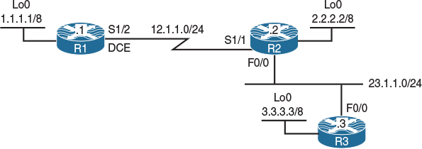
Figure 8-5 OSPF Point-to-Point Network Types
Task 1
Configure OSPF Area 0 on the routers in Figure 8-5 based on the following policies:
![]() The loopback0 interface of these routers should be advertised with their correct mask.
The loopback0 interface of these routers should be advertised with their correct mask.
![]() Use 0.0.0.1, 0.0.0.2, and 0.0.0.3 as the router IDs of R1, R2, and R3, respectively.
Use 0.0.0.1, 0.0.0.2, and 0.0.0.3 as the router IDs of R1, R2, and R3, respectively.
![]() There should not be any DR/BDR election on any of the links.
There should not be any DR/BDR election on any of the links.
![]() Do not configure “point-to-multipoint” or “point-to-multipoint non-broadcast” on any of the links.
Do not configure “point-to-multipoint” or “point-to-multipoint non-broadcast” on any of the links.
On R1:
R1(config-if)# router ospf 1
R1(config-router)# router-id 0.0.0.1
R1(config-router)# network 1.1.1.1 0.0.0.0 area 0
R1(config-router)# network 12.1.1.1 0.0.0.0 area 0
R1(config-router)# interface loopback0
R1(config-if)# ip ospf network point-to-point
On R2:
R2(config)# router ospf 1
R2(config-router)# router-id 0.0.0.2
R2(config-router)# network 2.2.2.2 0.0.0.0 area 0
R2(config-router)# network 12.1.1.2 0.0.0.0 area 0
R2(config-router)# network 23.1.1.2 0.0.0.0 area 0
R2(config-router)# interface loopback0
R2(config-if)# ip ospf network point-to-point
You should see the following console message:
%OSPF-5-ADJCHG: Process 1, Nbr 0.0.0.1 on Serial1/1 from LOADING to FULL,
Loading Done
On R3:
R3(config)# router ospf 1
R3(config-router)# router-id 0.0.0.3
R3(config-router)# network 3.3.3.3 0.0.0.0 area 0
R3(config-router)# network 23.1.1.3 0.0.0.0 area 0
R3(config-router)# interface loopback0
R3(config-if)# ip ospf network point-to-point
You should also see the following console message:
%OSPF-5-ADJCHG: Process 1, Nbr 0.0.0.2 on FastEthernet0/0 from LOADING to FULL,
Loading Done
Let’s verify the configuration:
On R1:
R1# show ip route ospf | begin Gate
Gateway of last resort is not set
O 2.0.0.0/8 [110/782] via 12.1.1.2, 00:00:17, Serial1/2
O 3.0.0.0/8 [110/783] via 12.1.1.2, 00:00:17, Serial1/2
23.0.0.0/24 is subnetted, 1 subnets
O 23.1.1.0 [110/782] via 12.1.1.2, 00:00:17, Serial1/2
On R2:
R2# show ip route ospf | begin Gate
Gateway of last resort is not set
O 1.0.0.0/8 [110/782] via 12.1.1.1, 00:01:10, Serial1/1
O 3.0.0.0/8 [110/2] via 23.1.1.3, 00:02:02, FastEthernet0/0
On R3:
R3# show ip route ospf | begin Gate
Gateway of last resort is not set
O 1.0.0.0/8 [110/783] via 23.1.1.2, 00:01:39, FastEthernet0/0
O 2.0.0.0/8 [110/2] via 23.1.1.2, 00:02:41, FastEthernet0/0
12.0.0.0/24 is subnetted, 1 subnets
O 12.1.1.0 [110/782] via 23.1.1.2, 00:01:49, FastEthernet0/0
R3# show ip ospf neighbor
neighbor ID Pri State Dead Time Address Interface
0.0.0.2 1 FULL/BDR 00:00:33 23.1.1.2 FastEthernet0/0
The task states that there should no DR/BDR election, and because the use of both point-to-multipoint and point-to-multipoint non-broadcast is prohibited, the network type of the f0/0 interfaces of R2 and R3 should be changed to point-to-point:
On R2 and R3:
Rx(config)# interface FastEthernet0/0
Rx(config-if)# ip ospf network point-to-point
Let’s verify the configuration:
On R3:
R3# show ip route ospf | begin Gate
Gateway of last resort is not set
O 1.0.0.0/8 [110/783] via 23.1.1.2, 00:00:09, FastEthernet0/0
O 2.0.0.0/8 [110/2] via 23.1.1.2, 00:00:09, FastEthernet0/0
12.0.0.0/24 is subnetted, 1 subnets
O 12.1.1.0 [110/782] via 23.1.1.2, 00:00:09, FastEthernet0/0
Let’s verify some of the parameters on the interfaces that have a point-to-point network type:
On R1:
R1# show ip ospf interface serial1/2 | include Network|Hello
Internet Address 12.1.1.1/24, Area 0, Attached via network Statement
Process ID 1, router ID 0.0.0.1, network Type POINT_TO_POINT, Cost: 781
Timer intervals configured, Hello 10, Dead 40, Wait 40, Retransmit 5
Hello due in 00:00:01
You can see that with the OSPF point-to-point network type, there are no DR/BDR elections, and the hello and dead intervals are set to 10 and 40, respectively. You can also see that we did not experience any problems forming adjacency using multicast.
Here are the important points concerning OSPF point-to-point network types:
![]() Hellos are exchanged every 10 seconds, and the dead interval is set to 40 seconds.
Hellos are exchanged every 10 seconds, and the dead interval is set to 40 seconds.
![]() There is no DR/BDR election.
There is no DR/BDR election.
![]() The routers use 224.0.0.5 to form an adjacency and send hello messages.
The routers use 224.0.0.5 to form an adjacency and send hello messages.
![]() The next hop is the router that advertised the route; this is the neighboring router.
The next hop is the router that advertised the route; this is the neighboring router.
Erase the startup configuration of the routers as well as the config.text and vlan.dat files of the switches and then reload them before proceeding to the next lab.
Lab 8-5: OSPF Point-to-Multipoint and Point-to-Multipoint Non-Broadcast Networks
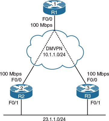
Figure 8-6 OSPF Point-to-Multipoint and Point-to-Multipoint Non-Broadcast Network
Figure 8-6 illustrates the topology that will used in the following tasks.
The DMVPN is configured in Phase 2 using static maps. R1 (the hub router) is configured with two static maps—one for each spoke. Routers R2 and R3 are configured with a single map for the hub.
Task 1
Configure OSPF Area 0 on the tunnel interfaces of these three routers. R2 and R3 should also run OSPF Area 0 on their f0/1 interface. If this configuration is performed successfully, the routers in this topology should have full reachability to every network in the topology. The tunnel interface of these routers should be configured as point-to-multipoint OSPF networks.
Use 0.0.0.1, 0.0.0.2, and 0.0.0.3 as the router IDs of R1, R2, and R3, respectively:
On All routers:
Rx(config)# interface tunnel 123
Rx(config-if)# ip ospf network point-to-multipoint
On R1:
R1(config)# router ospf 1
R1(config-router)# router-id 0.0.0.1
R1(config-router)# network 10.1.1.1 0.0.0.0 area 0
On R2:
R2(config)# router ospf 1
R2(config-router)# router-id 0.0.0.2
R2(config-router)# network 10.1.1.2 0.0.0.0 area 0
R2(config-router)# network 23.1.1.2 0.0.0.0 area 0
On R3:
R3(config)# router ospf 1
R3(config-router)# router-id 0.0.0.3
R3(config-router)# network 10.1.1.3 0.0.0.0 area 0
R3(config-router)# network 23.1.1.3 0.0.0.0 area 0
Let’s verify the configuration:
On R1:
R1# show ip ospf neighbor
The routers did not form an OSPF adjacency, so let’s look at the important points in OSPF point-to-multipoint network types:
![]() The routers use 224.0.0.5.
The routers use 224.0.0.5.
![]() There is no requirement for a DR or BDR.
There is no requirement for a DR or BDR.
![]() The next hop is the advertising router.
The next hop is the advertising router.
![]() Host routes are advertised automatically for NLRI in partial mesh topologies.
Host routes are advertised automatically for NLRI in partial mesh topologies.
Because the routers use a multicast address of 224.0.0.5, let’s see if the tunnel interfaces have multicast capability:
On R1:
R1# show run interface tunnel 123 | begin interface
interface Tunnel123
ip address 10.1.1.1 255.255.255.0
no ip redirects
ip nhrp map 10.1.1.3 192.1.3.3
ip nhrp map 10.1.1.2 192.1.2.2
ip nhrp network-id 111
ip ospf network point-to-multipoint
tunnel source FastEthernet0/0
tunnel mode gre multipoint
end
On R2:
R2# show run interface tunnel 123 | begin interface
interface Tunnel123
ip address 10.1.1.2 255.255.255.0
no ip redirects
ip nhrp map 10.1.1.1 192.1.1.1
ip nhrp network-id 222
ip ospf network point-to-multipoint
tunnel source FastEthernet0/0
tunnel mode gre multipoint
end
On R3:
R3# show run interface tunnel 123 | begin inter
interface Tunnel123
ip address 10.1.1.3 255.255.255.0
no ip redirects
ip nhrp map 10.1.1.1 192.1.1.1
ip nhrp network-id 333
ip ospf network point-to-multipoint
tunnel source FastEthernet0/0
tunnel mode gre multipoint
end
You can see the problem—the routers don’t have mapping for multicast. Let’s configure them:
On R1:
R1(config)# interface tunnel 123
R1(config-if)# ip nhrp map multicast 192.1.2.2
R1(config-if)# ip nhrp map multicast 192.1.3.3
On R3:
R3(config)# interface tunnel 123
R3(config-if)# ip nhrp map multicast 192.1.1.1
Now let’s verify the configuration:
On R1:
R1# show ip ospf neighbor
neighbor ID Pri State Dead Time Address Interface
0.0.0.2 0 FULL/ - 00:01:57 10.1.1.2 Tunnel123
0.0.0.3 0 FULL/ - 00:01:57 10.1.1.3 Tunnel123
R1# show ip route ospf | begin Gate
Gateway of last resort is not set
10.0.0.0/8 is variably subnetted, 4 subnets, 2 masks
O 10.1.1.2/32 [110/1000] via 10.1.1.2, 00:02:06, Tunnel123
O 10.1.1.3/32 [110/1000] via 10.1.1.3, 00:02:06, Tunnel123
23.0.0.0/24 is subnetted, 1 subnets
O 23.1.1.0 [110/1001] via 10.1.1.3, 00:02:06, Tunnel123
[110/1001] via 10.1.1.2, 00:02:06, Tunnel123
Here’s a summary of some of the important points in OSPF point-to-multipoint networks:
![]() The routers use 224.0.0.5.
The routers use 224.0.0.5.
![]() There is no requirement for a DR or BDR.
There is no requirement for a DR or BDR.
![]() The next hop is the advertising router.
The next hop is the advertising router.
![]() Host routes are advertised automatically for NLRI in partial Mesh topologies.
Host routes are advertised automatically for NLRI in partial Mesh topologies.
We have fixed the first point by mapping multicast. Let’s verify the second point:
R1# show ip ospf neighbor
neighbor ID Pri State Dead Time Address Interface
0.0.0.2 0 FULL/ - 00:01:54 10.1.1.2 Tunnel123
0.0.0.3 0 FULL/ - 00:01:58 10.1.1.3 Tunnel123
Now let’s verify the third and fourth points:
On R2:
R2# show ip route ospf | begin Gate
Gateway of last resort is not set
10.0.0.0/8 is variably subnetted, 4 subnets, 2 masks
O 10.1.1.1/32 [110/1000] via 10.1.1.1, 00:06:48, Tunnel123
O 10.1.1.3/32 [110/1] via 23.1.1.3, 00:20:03, FastEthernet0/1
You can see that the next-hop IP address is the IP address of the router that originated the route. You can also see the host routes that are advertised for reachability.
Task 2
Because R2’s connection to the cloud is 10 Mbps and R3’s connection is 100 Mbps, R1 should not perform equal-cost load sharing, and R1 should go through R3 to reach network 23.1.1.0/24. Do not configure Policy Based Routing (PBR) or use the ip ospf cost command to accomplish this task.
As you can see, R2’s f0/0 is configured as 10 Mbps, whereas the f0/0 interfaces of R1 and R3 are configured as 100 Mbps. Since OSPF is running on the tunnel interfaces of these routers, OSPF will not see the actual cost of the f0/0 interfaces; therefore, a suboptimal routing can result.
In order to accomplish this task, you can change the OSPF network type. If the network type is changed to point-to-multipoint non-broadcast, then neighbor commands must be configured on the hub router. In this network type, the neighbor command can be configured with a cost that can make the connection through a given neighbor more attractive. Let’s configure this.
First, let’s verify the routing table of R1:
R1# show ip route ospf | begin Gate
Gateway of last resort is not set
10.0.0.0/8 is variably subnetted, 4 subnets, 2 masks
O 10.1.1.2/32 [110/1000] via 10.1.1.2, 00:02:06, Tunnel123
O 10.1.1.3/32 [110/1000] via 10.1.1.3, 00:02:06, Tunnel123
23.0.0.0/24 is subnetted, 1 subnets
O 23.1.1.0 [110/1001] via 10.1.1.3, 00:02:06, Tunnel123
[110/1001] via 10.1.1.2, 00:02:06, Tunnel123
On All Routers:
Rx(config)# interface tunnel 123
Rx(config-if)# ip ospf network point-to-multipointerface non-broadcast
R1(config)# router ospf 1
R1(config-router)# neighbor 10.1.1.2 cost 20
R1(config-router)# neighbor 10.1.1.3 cost 1
You should see the following console messages stating that the neighbor adjacency has been established:
%OSPF-5-ADJCHG: Process 1, Nbr 0.0.0.3 on Tunnel123 from LOADING to FULL,
Loading Done
%OSPF-5-ADJCHG: Process 1, Nbr 0.0.0.2 on Tunnel123 from LOADING to FULL,
Loading Done
Let’s verify the configuration:
On R1:
R1# show ip route ospf | begin Gate
Gateway of last resort is not set
10.0.0.0/8 is variably subnetted, 4 subnets, 2 masks
O 10.1.1.2/32 [110/2] via 10.1.1.3, 00:02:55, Tunnel123
O 10.1.1.3/32 [110/1] via 10.1.1.3, 00:02:55, Tunnel123
23.0.0.0/24 is subnetted, 1 subnets
O 23.1.1.0 [110/2] via 10.1.1.3, 00:02:55, Tunnel123
Let’s summarize the important points in OSPF point-to-multipoint network types:
![]() There is no DR/BDR requirement.
There is no DR/BDR requirement.
![]() Hello and dead intervals are 30 and 120 seconds, respectively.
Hello and dead intervals are 30 and 120 seconds, respectively.
![]() The next hop is the neighboring router.
The next hop is the neighboring router.
![]() There is no multicast capability, so neighbor commands must be configured to establish OSPF adjacencies.
There is no multicast capability, so neighbor commands must be configured to establish OSPF adjacencies.
Erase the startup configuration of the routers as well as the config.text and vlan.dat files of the switches and then reload them before proceeding to the next lab.
Lab 8-6: OSPF Authentication
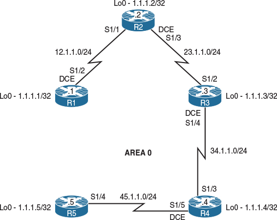
Figure 8-7 OSPF Authentication
Figure 8-7 illustrates the topology that will used in the following tasks.
Task 1
Configure the directly connected interfaces of all routers in Area 0. Configure the router IDs to be 0.0.0.x, where x is the router number:
On R1:
R1(config)# router ospf 1
R1(config-router)# router-id 0.0.0.1
R1(config-router)# network 1.1.1.1 0.0.0.0 area 0
R1(config-router)# network 12.1.1.1 0.0.0.0 area 0
On R2:
R2(config-if)# router ospf 1
R2(config-router)# router-id 0.0.0.2
R2(config-router)# network 1.1.1.2 0.0.0.0 area 0
R2(config-router)# network 12.1.1.2 0.0.0.0 area 0
R2(config-router)# network 23.1.1.2 0.0.0.0 area 0
You should see the following console message:
%OSPF-5-ADJCHG: Process 1, Nbr 0.0.0.1 on Serial1/1 from LOADING to FULL,
Loading Done
On R3:
R3(config-if)# router ospf 1
R3(config-router)# router-id 0.0.0.3
R3(config-router)# network 1.1.1.3 0.0.0.0 area 0
R3(config-router)# network 23.1.1.3 0.0.0.0 area 0
R3(config-router)# network 34.1.1.3 0.0.0.0 area 0
The peering with 0.0.0.2 will come up quickly.
%OSPF-5-ADJCHG: Process 1, Nbr 0.0.0.2 on Serial1/2 from LOADING to FULL,
Loading Done
On R4:
R4(config-if)# router ospf 1
R4(config-router)# router-id 0.0.0.4
R4(config-router)# network 1.1.1.4 0.0.0.0 area 0
R4(config-router)# network 34.1.1.4 0.0.0.0 area 0
R4(config-router)# network 45.1.1.4 0.0.0.0 area 0
Now 0.0.0.3 becomes a peer as evidenced by the console output.
%OSPF-5-ADJCHG: Process 1, Nbr 0.0.0.3 on Serial1/3 from LOADING to FULL,
Loading Done
On R5:
R5(config-if)# router ospf 1
R5(config-router)# router-id 0.0.0.5
R5(config-router)# network 45.1.1.5 0.0.0.0 area 0
R5(config-router)# network 1.1.1.5 0.0.0.0 area 0
Lastly, 0.0.0.4 joins the OSPF domain.
%OSPF-5-ADJCHG: Process 1, Nbr 0.0.0.4 on Serial1/4 from LOADING to FULL,
Loading Done
Let’s verify the configuration:
On R1:
R1# show ip route ospf | begin Gate
Gateway of last resort is not set
1.0.0.0/32 is subnetted, 5 subnets
O 1.1.1.2 [110/782] via 12.1.1.2, 00:01:52, Serial1/2
O 1.1.1.3 [110/1563] via 12.1.1.2, 00:01:19, Serial1/2
O 1.1.1.4 [110/2344] via 12.1.1.2, 00:01:03, Serial1/2
O 1.1.1.5 [110/3125] via 12.1.1.2, 00:00:39, Serial1/2
23.0.0.0/24 is subnetted, 1 subnets
O 23.1.1.0 [110/1562] via 12.1.1.2, 00:01:42, Serial1/2
34.0.0.0/24 is subnetted, 1 subnets
O 34.1.1.0 [110/2343] via 12.1.1.2, 00:01:19, Serial1/2
45.0.0.0/24 is subnetted, 1 subnets
O 45.1.1.0 [110/3124] via 12.1.1.2, 00:00:53, Serial1/2
On R5:
R5# show ip route ospf | begin Gate
Gateway of last resort is not set
1.0.0.0/32 is subnetted, 5 subnets
O 1.1.1.1 [110/3125] via 45.1.1.4, 00:01:56, Serial1/4
O 1.1.1.2 [110/2344] via 45.1.1.4, 00:01:56, Serial1/4
O 1.1.1.3 [110/1563] via 45.1.1.4, 00:01:56, Serial1/4
O 1.1.1.4 [110/782] via 45.1.1.4, 00:01:56, Serial1/4
12.0.0.0/24 is subnetted, 1 subnets
O 12.1.1.0 [110/3124] via 45.1.1.4, 00:01:56, Serial1/4
23.0.0.0/24 is subnetted, 1 subnets
O 23.1.1.0 [110/2343] via 45.1.1.4, 00:01:56, Serial1/4
34.0.0.0/24 is subnetted, 1 subnets
O 34.1.1.0 [110/1562] via 45.1.1.4, 00:01:56, Serial1/4
Task 2
Configure plaintext authentication on all routers in Area 0. You must use a router configuration command as part of the solution to this task. Use “Cisco” as the password for this authentication.
OSPF supports two types of authentication: plaintext (64-bit password) and MD5 (which consists of a key ID and 128-bit password). In OSPF, authentication must be enabled and then applied.
In OSPF, authentication can be enabled in two different ways. One way to enable OSPF authentication is to configure it in the router configuration mode, in which case authentication is enabled globally on all OSPF-enabled interfaces in the specified area. The second way is to enable authentication directly on the interface for which authentication is required.
Because this task states that a router configuration mode must be used, OSPF authentication is enabled in the router configuration mode.
So that you understand OSPF’s authentication, let’s enable debug ip ospf packet on R1:
On R1:
R1# debug ip ospf packet
OSPF packet debugging is on
You should see the following debug messages:
OSPF-1 PAK : rcv. v:2 t:1 l:48 rid:0.0.0.2 aid:0.0.0.0 chk:EC97 aut:0 auk:
from Serial1/2
The output of the preceding debug message shows the following:
![]() V:2—This indicates OSPF version 2
V:2—This indicates OSPF version 2
![]() T:1—This identifies the packet type (in this case, packet type 1, a hello message).
T:1—This identifies the packet type (in this case, packet type 1, a hello message).
![]() l:48—The length of these messages is 48 bytes.
l:48—The length of these messages is 48 bytes.
![]() rid:0.0.0.2—This is the router ID of R2, the sending router.
rid:0.0.0.2—This is the router ID of R2, the sending router.
![]() aid:0.0.0.0—This is the area ID.
aid:0.0.0.0—This is the area ID.
![]() aut:0—This means that there is no authentication.
aut:0—This means that there is no authentication.
![]() auk:—No authentication key is defined.
auk:—No authentication key is defined.
![]() from Serial1/2—The packet is received through the local router’s S1/2 interface.
from Serial1/2—The packet is received through the local router’s S1/2 interface.
On R1:
R1(config)# router ospf 1
R1(config-router)# area 0 authentication
R1(config-router)# interface serial1/2
R1(config-subif)# ip ospf authentication-key Cisco
On R2:
R2(config)# router ospf 1
R2(config-router)# area 0 authentication
R2(config-router)# interface s1/1
R2(config-subif)# ip ospf authentication-key Cisco
On R1, you should now see in the output of the OSPF debug packets that the authentication type is set to 1, which means cleartext authentication (you will see the MD5 authentication type later in this lab):
OSPF-1 PAK : rcv. v:2 t:1 l:48 rid:0.0.0.2 aid:0.0.0.0 chk:EC96 aut:1 auk:
from Serial1/2
Let’s turn off the debug packets:
R1# undebug all
All possible debugging has been turned off
Now we can continue with R2’s configuration:
On R2:
R2(config-if)# interface serial1/3
R2(config-if)# ip ospf authentication-key Cisco
Let’s verify the configuration:
On R2:
R2# show ip ospf interface serial1/1 | include auth
Simple password authentication enabled
Note the output of the preceding show command, which verifies that simple password authentication is enabled and applied to the s1/1 interface.
R2# show ip ospf neighbor
neighbor ID Pri State Dead Time Address Interface
0.0.0.1 0 FULL/ - 00:00:34 12.1.1.1 Serial1/1
R2# show ip route ospf | be Gate
Gateway of last resort is not set
1.0.0.0/32 is subnetted, 2 subnets
O 1.1.1.1 [110/782] via 12.1.1.1, 00:06:32, Serial1/1
Let’s configure R3 and R4:
On R3:
R3(config)# router ospf 1
R3(config-router)# area 0 authentication
R3(config)# interface serial1/2
R3(config-if)# ip ospf authentication-key Cisco
R3(config)# interface serial1/4
R3(config-if)# ip ospf authentication-key Cisco
You should see the following console message stating that the adjacency transitioned from FULL to DOWN (this is because authentication is not configured on R4):
%OSPF-5-ADJCHG: Process 1, Nbr 0.0.0.4 on Serial1/4 from FULL to DOWN,
Neighbor Down: Dead timer expired
Let’s verify the configuration:
On R3:
R3# show ip route ospf | begin Gate
Gateway of last resort is not set
1.0.0.0/32 is subnetted, 3 subnets
O 1.1.1.1 [110/1563] via 23.1.1.2, 00:00:29, Serial1/2
O 1.1.1.2 [110/782] via 23.1.1.2, 00:00:29, Serial1/2
12.0.0.0/24 is subnetted, 1 subnets
O 12.1.1.0 [110/1562] via 23.1.1.2, 00:00:29, Serial1/2
On R4:
R4(config)# router ospf 1
R4(config-router)# area 0 authentication
R4(config)# interface serial1/3
R4(config-if)# ip ospf authentication-key Cisco
You should see the following console message:
%OSPF-5-ADJCHG: Process 1, Nbr 0.0.0.3 on Serial1/3 from LOADING to FULL,
Loading Done
R4(config-if)# interface serial1/5
R4(config-if)# ip ospf authentication-key Cisco
Let’s verify the configuration. On R4, you should not see the 1.1.1.5/32 prefix in the routing table. If you still see this prefix in R4’s routing table, you may have to wait for the adjacency to R5 to go down before entering the following show command:
R4# show ip route ospf | begin Gate
Gateway of last resort is not set
1.0.0.0/32 is subnetted, 4 subnets
O 1.1.1.1 [110/2344] via 34.1.1.3, 00:00:41, Serial1/3
O 1.1.1.2 [110/1563] via 34.1.1.3, 00:00:41, Serial1/3
O 1.1.1.3 [110/782] via 34.1.1.3, 00:00:41, Serial1/3
12.0.0.0/24 is subnetted, 1 subnets
O 12.1.1.0 [110/2343] via 34.1.1.3, 00:00:41, Serial1/3
23.0.0.0/24 is subnetted, 1 subnets
O 23.1.1.0 [110/1562] via 34.1.1.3, 00:00:41, Serial1/3
Let’s configure R5:
On R5:
R5(config)# router ospf 1
R5(config-router)# area 0 authentication
R5(config-router)# interface serial1/4
R5(config-if)# ip ospf authentication-key Cisco
You should see the following console message:
%OSPF-5-ADJCHG: Process 1, Nbr 0.0.0.4 on Serial1/4 from LOADING to FULL,
Loading Done
Let’s verify the configuration:
On R5:
R5# show ip route ospf | begin Gate
Gateway of last resort is not set
1.0.0.0/32 is subnetted, 5 subnets
O 1.1.1.1 [110/3125] via 45.1.1.4, 00:00:10, Serial1/4
O 1.1.1.2 [110/2344] via 45.1.1.4, 00:00:10, Serial1/4
O 1.1.1.3 [110/1563] via 45.1.1.4, 00:00:10, Serial1/4
O 1.1.1.4 [110/782] via 45.1.1.4, 00:00:10, Serial1/4
12.0.0.0/24 is subnetted, 1 subnets
O 12.1.1.0 [110/3124] via 45.1.1.4, 00:00:10, Serial1/4
23.0.0.0/24 is subnetted, 1 subnets
O 23.1.1.0 [110/2343] via 45.1.1.4, 00:00:10, Serial1/4
34.0.0.0/24 is subnetted, 1 subnets
O 34.1.1.0 [110/1562] via 45.1.1.4, 00:00:10, Serial1/4
Task 3
Remove the authentication configuration from the previous task and ensure that every router sees every route advertised in Area 0:
On All Routers:
Rx(config)# router ospf 1
Rx(config-router)# no area 0 authentication
On R1:
R1(config)# interface serial1/2
R1(config-if)# no ip ospf authentication-key Cisco
On R2:
R2(config)# interface serial1/1
R2(config-if)# no ip ospf authentication-key Cisco
R2(config-if)# interface serial1/3
R2(config-if)# no ip ospf authentication-key Cisco
On R3:
R3(config-if)# interface s1/2
R3(config-if)# no ip ospf authentication-key Cisco
R3(config-if)# interface s1/4
R3(config-if)# no ip ospf authentication-key Cisco
On R4:
R4(config)# interface serial1/3
R4(config-if)# no ip ospf authentication-key Cisco
R4(config)# interface s1/5
R4(config-if)# no ip ospf authentication-key Cisco
On R5:
R5(config)# interface serial1/4
R5(config-if)# no ip ospf authentication-key Cisco
Let’s verify the configuration:
On R1:
R1# show ip route ospf | include O
Gateway of last resort is not set
1.0.0.0/32 is subnetted, 5 subnets
O 1.1.1.2 [110/782] via 12.1.1.2, 00:09:49, Serial1/2
O 1.1.1.3 [110/1563] via 12.1.1.2, 00:06:40, Serial1/2
O 1.1.1.4 [110/2344] via 12.1.1.2, 00:05:25, Serial1/2
O 1.1.1.5 [110/3125] via 12.1.1.2, 00:03:57, Serial1/2
23.0.0.0/24 is subnetted, 1 subnets
O 23.1.1.0 [110/1562] via 12.1.1.2, 00:09:49, Serial1/2
34.0.0.0/24 is subnetted, 1 subnets
O 34.1.1.0 [110/2343] via 12.1.1.2, 00:06:40, Serial1/2
45.0.0.0/24 is subnetted, 1 subnets
O 45.1.1.0 [110/3124] via 12.1.1.2, 00:05:25, Serial1/2
Task 4
Configure MD5 authentication on all the serial links in this area. You should use a router configuration command as part of the solution to this task. Use “Cisco” as the password for this authentication.
The following command enables MD5 authentication on the routers using the router configuration mode:
On All Routers:
Rx(config)# router ospf 1
Rx(config-router)# area 0 authentication message-digest
On R1:
R1(config)# interface serial1/2
R1(config-if)# ip ospf message-digest-key 1 md5 Cisco
On R2:
R2(config)# interface serial1/1
R2(config-if)# ip ospf message-digest-key 1 md5 Cisco
Let’s see the debug output and verify the authentication type and key:
On R1:
R1# debug ip ospf packet
OSPF packet debugging is on
You should see the following debug output on your console:
OSPF-1 PAK : rcv. v:2 t:1 l:48 rid:0.0.0.2 aid:0.0.0.0 chk:0 aut:2 keyid:1
seq:0x536538E9 from Serial1/2
You can clearly see aut:2. This identifies the authentication type, which is set to 2, meaning that it’s MD5 authentication. You can also see keyid:1, which means that the key value used in the configuration is 1.
On R2:
R2(config-if)# interface serial1/3
R2(config-if)# ip ospf message-digest-key 1 MD5 Cisco
Let’s verify the configuration. Before doing so, however, we need to disable the debug on R1:
On R1:
R1# undebug all
All possible debugging has been turned off
On R2:
R2# show ip ospf interface serial1/1 | begin Message
Message digest authentication enabled
Youngest key id is 1
Note The output of the preceding show command reveals that MD5 authentication is enabled and applied and that the key ID is set to 1.
R2# show ip route ospf | begin Gate
Gateway of last resort is not set
1.0.0.0/32 is subnetted, 2 subnets
O 1.1.1.1 [110/782] via 12.1.1.1, 00:18:36, Serial1/1
On R3:
R3(config)# interface serial1/2
R3(config-if)# ip ospf message-digest-key 1 md5 Cisco
R3(config)# interface serial1/4
R3(config-if)# ip ospf message-digest-key 1 md5 Cisco
Let’s verify the configuration. Once the OSPF adjacency to R2 comes up and the adjacency to R4 goes down, you should see the following output:
On R3:
R3# show ip route ospf | begin Gate
Gateway of last resort is not set
1.0.0.0/32 is subnetted, 3 subnets
O 1.1.1.1 [110/1563] via 23.1.1.2, 00:00:54, Serial1/2
O 1.1.1.2 [110/782] via 23.1.1.2, 00:00:54, Serial1/2
12.0.0.0/24 is subnetted, 1 subnets
O 12.1.1.0 [110/1562] via 23.1.1.2, 00:00:54, Serial1/2
On R4:
R4(config)# interface serial1/3
R4(config-if)# ip ospf message-digest-key 1 md5 Cisco
R4(config)# interface serial1/5
R4(config-if)# ip ospf message-digest-key 1 MD5 Cisco
Let’s verify the configuration. Once the OSPF adjacency to R3 comes up and the adjacency to R5 goes down, you should see the following output:
On R4:
R4# show ip route ospf | begin Gate
Gateway of last resort is not set
1.0.0.0/32 is subnetted, 4 subnets
O 1.1.1.1 [110/2344] via 34.1.1.3, 00:00:58, Serial1/3
O 1.1.1.2 [110/1563] via 34.1.1.3, 00:00:58, Serial1/3
O 1.1.1.3 [110/782] via 34.1.1.3, 00:00:58, Serial1/3
12.0.0.0/24 is subnetted, 1 subnets
O 12.1.1.0 [110/2343] via 34.1.1.3, 00:00:58, Serial1/3
23.0.0.0/24 is subnetted, 1 subnets
O 23.1.1.0 [110/1562] via 34.1.1.3, 00:00:58, Serial1/3
On R5:
R5(config)# interface serial1/4
R5(config-subif)# ip ospf message-digest-key 1 md5 Cisco
Let’s verify the configuration:
On R5:
R5# show ip route ospf | begin Gate
Gateway of last resort is not set
1.0.0.0/32 is subnetted, 5 subnets
O 1.1.1.1 [110/3125] via 45.1.1.4, 00:00:07, Serial1/4
O 1.1.1.2 [110/2344] via 45.1.1.4, 00:00:07, Serial1/4
O 1.1.1.3 [110/1563] via 45.1.1.4, 00:00:07, Serial1/4
O 1.1.1.4 [110/782] via 45.1.1.4, 00:00:07, Serial1/4
12.0.0.0/24 is subnetted, 1 subnets
O 12.1.1.0 [110/3124] via 45.1.1.4, 00:00:07, Serial1/4
23.0.0.0/24 is subnetted, 1 subnets
O 23.1.1.0 [110/2343] via 45.1.1.4, 00:00:07, Serial1/4
34.0.0.0/24 is subnetted, 1 subnets
O 34.1.1.0 [110/1562] via 45.1.1.4, 00:00:07, Serial1/4
Task 5
Remove the authentication configuration from the previous task and ensure that every router sees every route advertised in Area 0:
On All Routers:
Rx(config)# router ospf 1
Rx(config-router)# no area 0 authentication message-digest
On R1:
R1(config)# interface serial1/2
R1(config-if)# no ip ospf message-digest-key 1 MD5 Cisco
On R2:
R2(config)# interface serial1/1
R2(config-if)# no ip ospf message-digest-key 1 MD5 Cisco
R2(config)# interface serial1/3
R2(config-if)# no ip ospf message-digest-key 1 MD5 Cisco
On R3:
R3(config)# interface serial1/2
R3(config-if)# no ip ospf message-digest-key 1 MD5 Cisco
R3(config)# interface serial1/4
R3(config-if)# no ip ospf message-digest-key 1 MD5 Cisco
On R4:
R4(config)# interface serial1/3
R4(config-if)# no ip ospf message-digest-key 1 MD5 Cisco
R4(config)# interface serial1/5
R4(config-if)# no ip ospf message-digest-key 1 MD5 Cisco
Let’s verify the configuration:
On R5:
R5# show ip route ospf | begin Gate
Gateway of last resort is not set
1.0.0.0/32 is subnetted, 5 subnets
O 1.1.1.1 [110/3125] via 45.1.1.4, 00:04:50, Serial1/4
O 1.1.1.2 [110/2344] via 45.1.1.4, 00:04:50, Serial1/4
O 1.1.1.3 [110/1563] via 45.1.1.4, 00:04:50, Serial1/4
O 1.1.1.4 [110/782] via 45.1.1.4, 00:04:50, Serial1/4
12.0.0.0/24 is subnetted, 1 subnets
O 12.1.1.0 [110/3124] via 45.1.1.4, 00:04:50, Serial1/4
23.0.0.0/24 is subnetted, 1 subnets
O 23.1.1.0 [110/2343] via 45.1.1.4, 00:04:50, Serial1/4
34.0.0.0/24 is subnetted, 1 subnets
O 34.1.1.0 [110/1562] via 45.1.1.4, 00:04:50, Serial1/4
Task 6
Configure MD5 authentication between R1 and R2. You should use a router configuration command as part of the solution to this task. Also, use “ccie” as the password.
On Both Routers:
Rx(config)# router ospf 1
Rx(config-router)# area 0 authentication message-digest
On R1:
R1(config)# interface serial1/2
R1(config-if)# ip ospf message-digest-key 1 MD5 ccie
On R2:
R2(config)# interface serial1/1
R2(config-if)# ip ospf message-digest-key 1 MD5 ccie
You should see the following console messages:
%OSPF-5-ADJCHG: Process 1, Nbr 0.0.0.1 on Serial1/1 from LOADING to FULL,
Loading Done
Then, you should see the following console message stating that the local router no longer has an adjacency with R3 with a router ID of 0.0.0.3:
%OSPF-5-ADJCHG: Process 1, Nbr 0.0.0.3 on Serial1/3 from FULL to DOWN,
neighbor Down: Dead timer expired
Let’s verify the configuration:
On R2:
R2# show ip route ospf | begin Gate
Gateway of last resort is not set
1.0.0.0/32 is subnetted, 2 subnets
O 1.1.1.1 [110/782] via 12.1.1.1, 00:36:55, Serial1/1
Note that because authentication is enabled in the router configuration mode, it is applied to every interface that is running in Area 0; therefore, every router in Area 0 must have the area 0 authentication message-digest command configured. Because R3 does not have MD5 authentication enabled, these routers will drop their adjacency.
Let’s verify the configuration:
On R2:
R2# show ip ospf neighbors
neighbor ID Pri State Dead Time Address Interface
0.0.0.1 0 FULL/ - 00:00:39 12.1.1.1 Serial1/1
Here are two solutions to fix this problem:
![]() Enable authentication on R3. However, if authentication is enabled on R3 under router OSPF, then R4 will drop the adjacency. Therefore, if router configuration mode must be used as part of the solution (based on the task), authentication needs to be enabled on R3, R4, and R5.
Enable authentication on R3. However, if authentication is enabled on R3 under router OSPF, then R4 will drop the adjacency. Therefore, if router configuration mode must be used as part of the solution (based on the task), authentication needs to be enabled on R3, R4, and R5.
![]() Disable authentication under the S1/3 interface. If authentication is disabled on the interface facing R3, then R3, R4, and R5 won’t need to have authentication enabled.
Disable authentication under the S1/3 interface. If authentication is disabled on the interface facing R3, then R3, R4, and R5 won’t need to have authentication enabled.
Let’s configure the preceding solutions and verify them. We’ll start with Solution 1:
On R3, R4 and R5:
Rx(config)# router ospf 1
Rx(config-router)# area 0 authentication message-digest
You should see the following console message on R3:
%OSPF-5-ADJCHG: Process 1, Nbr 0.0.0.2 on Serial1/2 from LOADING to FULL,
Loading Done
Let’s verify the configuration:
On R2:
R2# show ip route ospf | begin Gate
Gateway of last resort is not set
1.0.0.0/32 is subnetted, 5 subnets
O 1.1.1.1 [110/782] via 12.1.1.1, 00:43:45, Serial1/1
O 1.1.1.3 [110/782] via 23.1.1.3, 00:00:57, Serial1/3
O 1.1.1.4 [110/1563] via 23.1.1.3, 00:00:57, Serial1/3
O 1.1.1.5 [110/2344] via 23.1.1.3, 00:00:57, Serial1/3
34.0.0.0/24 is subnetted, 1 subnets
O 34.1.1.0 [110/1562] via 23.1.1.3, 00:00:57, Serial1/3
45.0.0.0/24 is subnetted, 1 subnets
O 45.1.1.0 [110/2343] via 23.1.1.3, 00:00:57, Serial1/3
Now let’s try Solution 2:
On R3, R4 and R5:
Rx(config)# router ospf 1
Rx(config-router)# no area 0 authentication message-digest
You should see the following console message after the dead interval expires:
%OSPF-5-ADJCHG: Process 1, Nbr 0.0.0.3 on Serial1/3 from FULL to DOWN,
neighbor Down: Dead timer expired
Let’s verify the configuration:
On R2:
R2# show ip route ospf | begin Gate
Gateway of last resort is not set
1.0.0.0/32 is subnetted, 2 subnets
O 1.1.1.1 [110/782] via 12.1.1.1, 00:45:32, Serial1/1
In this solution, authentication is disabled on R2’s interface facing R3 using the ip ospf authentication null interface configuration command, meaning that there is no need to have authentication downstream to the S1/3 interface of R2. Therefore, R3, R4, and R5 do not need to have authentication enabled.
On R2:
R2(config)# interface serial1/3
R2(config-if)# ip ospf authentication null
You should see the following console message on R2:
%OSPF-5-ADJCHG: Process 1, Nbr 0.0.0.3 on Serial1/3 from LOADING to FULL,
Loading Done
Let’s verify the configuration:
On R2:
R2# show ip route ospf | include O
Gateway of last resort is not set
1.0.0.0/32 is subnetted, 5 subnets
O 1.1.1.1 [110/782] via 12.1.1.1, 00:47:16, Serial1/1
O 1.1.1.3 [110/782] via 23.1.1.3, 00:00:20, Serial1/3
O 1.1.1.4 [110/1563] via 23.1.1.3, 00:00:20, Serial1/3
O 1.1.1.5 [110/2344] via 23.1.1.3, 00:00:20, Serial1/3
34.0.0.0/24 is subnetted, 1 subnets
O 34.1.1.0 [110/1562] via 23.1.1.3, 00:00:20, Serial1/3
45.0.0.0/24 is subnetted, 1 subnets
O 45.1.1.0 [110/2343] via 23.1.1.3, 00:00:20, Serial1/3
Task 7
Reconfigure the authentication password on R1 and R2 to be “CCIE12” without interrupting the link’s operation.
Let’s view the current configuration:
On R1:
R1# show ip ospf interface serial1/2 | begin Mess
Message digest authentication enabled
Youngest key id is 1
R1# show run interface serial1/2 | include ip ospf
ip ospf message-digest-key 1 md5 ccie
On R2:
R2# show ip ospf interface serial1/1 | begin Mess
Message digest authentication enabled
Youngest key id is 1
R2# show run interface serial1/1 | include ip ospf
ip ospf message-digest-key 1 md5 ccie
R2# show ip route ospf | begin Gate
Gateway of last resort is not set
1.0.0.0/32 is subnetted, 5 subnets
O 1.1.1.1 [110/782] via 12.1.1.1, 00:50:19, Serial1/1
O 1.1.1.3 [110/782] via 23.1.1.3, 00:03:23, Serial1/3
O 1.1.1.4 [110/1563] via 23.1.1.3, 00:03:23, Serial1/3
O 1.1.1.5 [110/2344] via 23.1.1.3, 00:03:23, Serial1/3
34.0.0.0/24 is subnetted, 1 subnets
O 34.1.1.0 [110/1562] via 23.1.1.3, 00:03:23, Serial1/3
45.0.0.0/24 is subnetted, 1 subnets
O 45.1.1.0 [110/2343] via 23.1.1.3, 00:03:23, Serial1/3
In order to change the password without any interruption to the link, you need to enter the second key with the required password:
Let’s verify the configuration:
On R1:
R1# show run interface serial1/2 | include ip ospf
ip ospf message-digest-key 1 md5 ccie
ip ospf message-digest-key 2 md5 CCIE12
R1# show ip ospf inter Serial1/2 | begin Message
Message digest authentication enabled
Youngest key id is 2
Rollover in progress, 1 neighbor(s) using the old key(s):
key id 1
Even though the second key (key 2) is only configured on R1, R1 and R2 are still authenticating based on the first key (key 1). This is revealed in the second line of the preceding show command.
R1 knows that the second key is configured (the second line in the preceding display) and that the rollover is in progress (the third line), but the other end (R2) has not been configured yet.
On R2:
R2(config)# interface serial1/1
R2(config-if)# ip ospf message-digest-key 2 md5 CCIE12
Let’s verify the configuration:
On R2:
R2# show ip ospf inter serial1/1 | begin Message
Message digest authentication enabled
Youngest key id is 2
Note Once R2 is configured, both routers (R1 and R2) will switch over and use the second key for their authentication.
On R1:
R1# show ip ospf interface serial1/2 | begin Message
Message digest authentication enabled
Youngest key id is 2
Once R1 and R2’s key rollover is completed and both routers display the same youngest key without the “rollover in progress” message, you can safely remove the prior key (in this case, key ID 1). Remember that the newest key is not determined based on the numerically higher value.
On R1:
R1# show run interface serial1/2 | include ip ospf
ip ospf message-digest-key 1 md5 ccie
ip ospf message-digest-key 2 md5 CCIE12
R1(config)# interface serial1/2
R1(config-subif)# no ip ospf message-digest-key 1 md5 ccie
On R2:
R2# show run interface serial1/1 | include ip ospf
ip ospf message-digest-key 1 md5 ccie
ip ospf message-digest-key 2 md5 CCIE12
R2(config)# interface serial1/1
R2(config-subif)# no ip ospf message-digest-key 1 md5 ccie
Task 8
Reconfigure the authentication password on R4 and R5 to be “Cisco45” without interrupting the link’s operation.
On R5:
R5(config)# interface serial1/4
R5(config-if)# ip ospf authentication message-digest
R5(config-if)# ip ospf message-digest-key 1 md5 Cisco45
On R4:
R4(config)# interface serial1/5
R4(config-if)# ip ospf authentication message-digest
R4(config-if)# ip ospf message-digest-key 1 md5 Cisco45
Note The authentication is enabled and applied directly under the interface for which authentication was required. When authentication is enabled directly under a given interface, authentication is enabled on that given interface only. Therefore, only the neighbor through that interface should have authentication enabled. This is called per-interface authentication.
Let’s verify the configuration:
On R5:
R5# show ip route ospf | begin Gate
Gateway of last resort is not set
1.0.0.0/32 is subnetted, 5 subnets
O 1.1.1.1 [110/3125] via 45.1.1.4, 00:00:09, Serial1/4
O 1.1.1.2 [110/2344] via 45.1.1.4, 00:00:09, Serial1/4
O 1.1.1.3 [110/1563] via 45.1.1.4, 00:00:09, Serial1/4
O 1.1.1.4 [110/782] via 45.1.1.4, 00:00:09, Serial1/4
12.0.0.0/24 is subnetted, 1 subnets
O 12.1.1.0 [110/3124] via 45.1.1.4, 00:00:09, Serial1/4
23.0.0.0/24 is subnetted, 1 subnets
O 23.1.1.0 [110/2343] via 45.1.1.4, 00:00:09, Serial1/4
34.0.0.0/24 is subnetted, 1 subnets
O 34.1.1.0 [110/1562] via 45.1.1.4, 00:00:09, Serial1/4
Task 9
Reconfigure the OSPF areas based on Table 8-2 and remove all the authentications configured on the routers. These routers should see all the routes advertised in this routing domain.
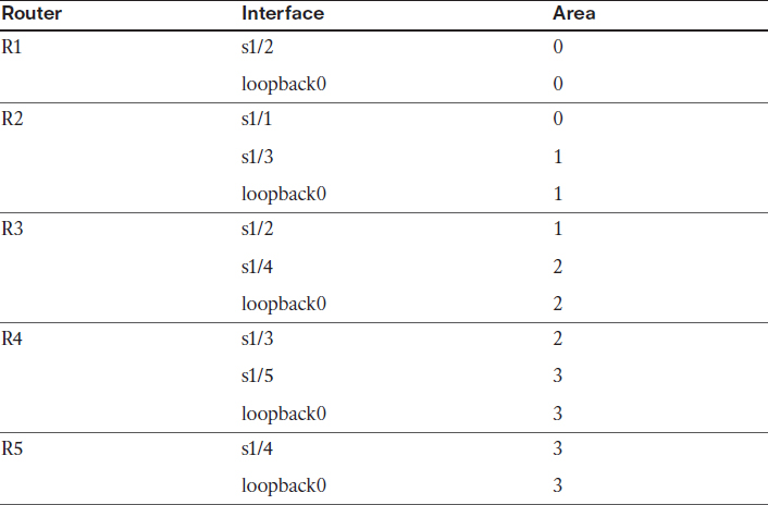
On All Routers:
Rx(config)# no router ospf 1
On R1:
R1(config)# router ospf 1
R1(config-router)# router-id 0.0.0.1
R1(config-router)# network 1.1.1.1 0.0.0.0 area 0
R1(config-router)# network 12.1.1.1 0.0.0.0 area 0
R1(config)# interface serial1/2
R1(config-subif)# no ip ospf message-digest-key 2 md5 CCIE12
On R2:
R2(config)# router ospf 1
R2(config-router)# router-id 0.0.0.2
R2(config-router)# network 12.1.1.2 0.0.0.0 area 0
R2(config-router)# network 23.1.1.2 0.0.0.0 area 1
R2(config-router)# network 1.1.1.2 0.0.0.0 area 1
R2(config)# interface serial1/1
R2(config-subif)# no ip ospf message-digest-key 2 md5 CCIE12
R2(config)# interface serial1/3
R2(config-subif)# no ip ospf authentication null
On R3:
R3(config)# router ospf 1
R3(config-router)# router-id 0.0.0.3
R3(config-router)# network 1.1.1.3 0.0.0.0 area 2
R3(config-router)# network 34.1.1.3 0.0.0.0 area 2
R3(config-router)# network 23.1.1.3 0.0.0.0 area 1
On R4:
R4(config)# router ospf 1
R4(config-router)# router-id 0.0.0.4
R4(config-router)# network 1.1.1.4 0.0.0.0 area 3
R4(config-router)# network 45.1.1.4 0.0.0.0 area 3
R4(config-router)# network 34.1.1.4 0.0.0.0 area 2
R4(config)# interface serial1/5
R4(config-if)# no ip ospf message-digest-key 1 md5 Cisco45
R4(config-if)# no ip ospf authentication message-digest
On R5:
R5(config)# router ospf 1
R5(config-router)# router-id 0.0.0.5
R5(config-router)# network 1.1.1.5 0.0.0.0 area 3
R5(config-router)# network 45.1.1.5 0.0.0.0 area 3
R5(config)# interface Serial1/4
R5(config-if)# no ip ospf message-digest-key 1 md5 Cisco45
R5(config-if)# no ip ospf authentication message-digest
In order for these routers to see all the routes advertised in this routing domain, you must configure virtual links because not all areas have connectivity to Area 0.
Area 1 has a connection to Area 0, but Areas 2 and 3 do not. Let’s begin with Area 2:
On R2:
R2(config)# router ospf 1
R2(config-router)# area 1 virtual-link 0.0.0.3
On R3:
R3(config)# router ospf 1
R3(config-router)# area 1 virtual-link 0.0.0.2
You should see the following console message:
%OSPF-5-ADJCHG: Process 1, Nbr 0.0.0.2 on OSPF_VL0 from LOADING to FULL,
Loading Done
Let’s connect Area 3 to Area 0:
On R3:
R3(config)# router ospf 1
R3(config-router)# area 2 virtual-link 0.0.0.4
On R4:
R4(config)# router ospf 1
R4(config-router)# area 2 virtual-link 0.0.0.3
You should see the following console message:
%OSPF-5-ADJCHG: Process 1, Nbr 0.0.0.3 on OSPF_VL2 from LOADING to FULL,
Loading Done
Let’s verify the configuration:
On R5:
R5# show ip route ospf | begin Gate
Gateway of last resort is not set
1.0.0.0/32 is subnetted, 5 subnets
O IA 1.1.1.1 [110/3125] via 45.1.1.4, 00:00:40, Serial1/4
O IA 1.1.1.2 [110/2344] via 45.1.1.4, 00:00:40, Serial1/4
O IA 1.1.1.3 [110/1563] via 45.1.1.4, 00:00:45, Serial1/4
O 1.1.1.4 [110/782] via 45.1.1.4, 00:03:17, Serial1/4
12.0.0.0/24 is subnetted, 1 subnets
O IA 12.1.1.0 [110/3124] via 45.1.1.4, 00:00:40, Serial1/4
23.0.0.0/24 is subnetted, 1 subnets
O IA 23.1.1.0 [110/2343] via 45.1.1.4, 00:00:40, Serial1/4
34.0.0.0/24 is subnetted, 1 subnets
O IA 34.1.1.0 [110/1562] via 45.1.1.4, 00:00:45, Serial1/4
Task 10
Configure MD5 authentication on the link between R1 and R2 in area 0. The password for this authentication should be set to “Micronics”. You should use router configuration mode to accomplish this task.
On R1 and R2:
Rx(config)# router ospf 1
Rx(config-router)# area 0 authentication message-digest
On R1:
R1(config)# interface serial1/2
R1(config-subif)# ip ospf message-digest-key 1 md5 Micronics
On R2:
R2(config)# interface serial1/1
R2(config-subif)# ip ospf message-digest-key 1 md5 Micronics
Let’s verify the configuration:
On R2:
R2# show ip route ospf | begin Gate
Gateway of last resort is not set
1.0.0.0/32 is subnetted, 5 subnets
O 1.1.1.1 [110/782] via 12.1.1.1, 00:07:10, Serial1/1
O IA 1.1.1.3 [110/782] via 23.1.1.3, 00:02:49, Serial1/3
O IA 1.1.1.4 [110/1563] via 23.1.1.3, 00:02:02, Serial1/3
O IA 1.1.1.5 [110/2344] via 23.1.1.3, 00:02:02, Serial1/3
34.0.0.0/24 is subnetted, 1 subnets
O IA 34.1.1.0 [110/1562] via 23.1.1.3, 00:02:49, Serial1/3
45.0.0.0/24 is subnetted, 1 subnets
O IA 45.1.1.0 [110/2343] via 23.1.1.3, 00:02:02, Serial1/3
Why do we see all the routes?
Let’s shut down the lo0 interface of R2, and then no shutdown the interface, and you should see the following console message within 40 seconds:
R2(config)# interface loopback 0
R2(config-if)# shutdown
Wait for the link to go down before entering the following command:
R2(config-if)# no shutdown
%OSPF-5-ADJCHG: Process 1, Nbr 0.0.0.3 on OSPF_VL0 from FULL to DOWN,
neighbor Down: Dead timer expired
R2# show ip route ospf | begin Gate
Gateway of last resort is not set
1.0.0.0/32 is subnetted, 2 subnets
O 1.1.1.1 [110/782] via 12.1.1.1, 00:24:18, Serial1/1
The reason we had to shutdown and then no shutdown an advertised route is because virtual links are demand circuits, and when a link is a demand circuit, OSPF suppresses the OSPF hello and refresh messages. Demand circuits are typically configured on switched virtual circuits (SVCs) such as ISDN, so when OSPF is enabled on a demand circuit, OSPF hello messages will keep that link up indefinitely. To handle this issue, you can configure the ip ospf demand-circuit command. With this command configured, OSPF will form an adjacency, and when the link goes down, the OSPF adjacency stays up. Because hello and refresh messages are suppressed, the link can stay down.
So when does this link ever come up? When there is a topology change. Enabling authentication is not a topology change, so this is the reason we had to shutdown and then no shutdown the interface; this triggers a topology change.
When a topology change is detected, the link comes up. When the link comes up and you have enabled authentication on one end of the link and not the other, the virtual link goes down and stays down until authentication is enabled on the other end of the link.
Note R2 does not have any other prefix in its routing table. This is because authentication is enabled directly under the router configuration mode of R1 and R2. When authentication is enabled in the router configuration mode, it is enabled on all links in the configured area—in this case, Area 0—and because virtual links are always in Area 0 (which cannot be changed), authentication must also be enabled on those links. There are three ways to fix this problem:
![]() Enable authentication on R3 and R4 in their router configuration mode. Remember R5 does not have a virtual link configured.
Enable authentication on R3 and R4 in their router configuration mode. Remember R5 does not have a virtual link configured.
![]() Enable authentication directly on the virtual links configured on R2, R3, and R4.
Enable authentication directly on the virtual links configured on R2, R3, and R4.
![]() Disable authentication on R2’s virtual link.
Disable authentication on R2’s virtual link.
Let’s implement the first solution:
On R3 and R4:
Rx(config)# router ospf 1
Rx(config-router)# area 0 authentication message-digest
Let’s verify the configuration:
On R5:
R5# show ip route ospf | begin Gate
Gateway of last resort is not set
1.0.0.0/32 is subnetted, 5 subnets
O IA 1.1.1.1 [110/3125] via 45.1.1.4, 00:00:17, Serial1/4
O IA 1.1.1.2 [110/2344] via 45.1.1.4, 00:08:25, Serial1/4
O IA 1.1.1.3 [110/1563] via 45.1.1.4, 00:08:30, Serial1/4
O 1.1.1.4 [110/782] via 45.1.1.4, 00:11:02, Serial1/4
12.0.0.0/24 is subnetted, 1 subnets
O IA 12.1.1.0 [110/3124] via 45.1.1.4, 00:00:17, Serial1/4
23.0.0.0/24 is subnetted, 1 subnets
O IA 23.1.1.0 [110/2343] via 45.1.1.4, 00:08:25, Serial1/4
34.0.0.0/24 is subnetted, 1 subnets
O IA 34.1.1.0 [110/1562] via 45.1.1.4, 00:08:30, Serial1/4
On R2:
R2# show ip route ospf | begin Gate
Gateway of last resort is not set
1.0.0.0/32 is subnetted, 5 subnets
O 1.1.1.1 [110/782] via 12.1.1.1, 00:14:03, Serial1/1
O IA 1.1.1.3 [110/782] via 23.1.1.3, 00:01:07, Serial1/3
O IA 1.1.1.4 [110/1563] via 23.1.1.3, 00:01:07, Serial1/3
O IA 1.1.1.5 [110/2344] via 23.1.1.3, 00:01:07, Serial1/3
34.0.0.0/24 is subnetted, 1 subnets
O IA 34.1.1.0 [110/1562] via 23.1.1.3, 00:01:07, Serial1/3
45.0.0.0/24 is subnetted, 1 subnets
O IA 45.1.1.0 [110/2343] via 23.1.1.3, 00:01:07, Serial1/3
Remember that when authentication is enabled in router configuration mode, authentication is enabled on all links/interfaces in the specified area. Because virtual links are always in Area 0, authentication will be enabled on all virtual links.
Let’s now implement the second solution. First, however, you need to remove the configuration from the previous solution:
On R3 and R4:
Rx(config)# router ospf 1
Rx(config-router)# no area 0 authentication message-digest
Rx# clear ip ospf process
Reset ALL OSPF processes? [no]: y
Let’s verify the configuration:
On R2:
R2# show ip route ospf | begin Gate
Gateway of last resort is not set
1.0.0.0/32 is subnetted, 2 subnets
O 1.1.1.1 [110/782] via 12.1.1.1, 00:16:26, Serial1/1
Let’s enable authentication on the virtual links:
R2(config)# router ospf 1
R2(config-router)# area 1 virtual-link 0.0.0.3 authentication message-digest
On R3:
R3(config)# router ospf 1
R3(config-router)# area 1 virtual-link 0.0.0.2 authentication message-digest
R3(config-router)# area 2 virtual-link 0.0.0.4 authentication message-digest
You should see the following console message:
%OSPF-5-ADJCHG: Process 1, Nbr 0.0.0.2 on OSPF_VL0 from LOADING to FULL,
Loading Done
On R4:
R4(config)# router ospf 1
R4(config-router)# area 2 virtual-link 0.0.0.3 authentication message-digest
Let’s verify the configuration:
On R5:
R5# show ip route ospf | begin Gate
Gateway of last resort is not set
1.0.0.0/32 is subnetted, 5 subnets
O IA 1.1.1.1 [110/3125] via 45.1.1.4, 00:01:22, Serial1/4
O IA 1.1.1.2 [110/2344] via 45.1.1.4, 00:04:19, Serial1/4
O IA 1.1.1.3 [110/1563] via 45.1.1.4, 00:04:24, Serial1/4
O 1.1.1.4 [110/782] via 45.1.1.4, 00:04:24, Serial1/4
12.0.0.0/24 is subnetted, 1 subnets
O IA 12.1.1.0 [110/3124] via 45.1.1.4, 00:01:22, Serial1/4
23.0.0.0/24 is subnetted, 1 subnets
O IA 23.1.1.0 [110/2343] via 45.1.1.4, 00:04:09, Serial1/4
34.0.0.0/24 is subnetted, 1 subnets
O IA 34.1.1.0 [110/1562] via 45.1.1.4, 00:04:24, Serial1/4
Now let’s implement the third solution. First, however, you need to remove the configuration from the previous solution:
On R2:
R2(config)# router ospf 1
R2(config-router)# no Area 1 virtual-link 0.0.0.3
R2(config-router)# area 1 virtual-link 0.0.0.3
On R3:
R3(config)# router ospf 1
R3(config-router)# no area 1 virtual-link 0.0.0.2
R3(config-router)# no area 2 virtual-link 0.0.0.4
R3(config-router)# area 1 virtual-link 0.0.0.2
R3(config-router)# area 2 virtual-link 0.0.0.4
On R4:
R4(config)# router ospf 1
R4(config-router)# no area 2 virtual-link 0.0.0.3
R4(config-router)# area 2 virtual-link 0.0.0.3
Let’s verify the configuration:
On R1:
R1# show ip route ospf | begin Gate
Gateway of last resort is not set
1.0.0.0/32 is subnetted, 2 subnets
O IA 1.1.1.2 [110/782] via 12.1.1.2, 00:15:54, Serial1/2
23.0.0.0/24 is subnetted, 1 subnets
O IA 23.1.1.0 [110/1562] via 12.1.1.2, 00:23:52, Serial1/2
Let’s implement the third solution:
On R2:
R2(config)# router ospf 1
R2(config-router)# area 1 virtual-link 0.0.0.3 authentication null
You should see the following console message:
%OSPF-5-ADJCHG: Process 1, Nbr 0.0.0.3 on OSPF_VL2 from LOADING to FULL,
Loading Done
On R2:
R2# show ip route ospf | begin Gate
Gateway of last resort is not set
1.0.0.0/32 is subnetted, 5 subnets
O 1.1.1.1 [110/782] via 12.1.1.1, 00:25:40, Serial1/1
O IA 1.1.1.3 [110/782] via 23.1.1.3, 00:00:48, Serial1/3
O IA 1.1.1.4 [110/1563] via 23.1.1.3, 00:00:48, Serial1/3
O IA 1.1.1.5 [110/2344] via 23.1.1.3, 00:00:48, Serial1/3
34.0.0.0/24 is subnetted, 1 subnets
O IA 34.1.1.0 [110/1562] via 23.1.1.3, 00:00:48, Serial1/3
45.0.0.0/24 is subnetted, 1 subnets
O IA 45.1.1.0 [110/2343] via 23.1.1.3, 00:00:48, Serial1/3
On R5:
R5# show ip route ospf | begin Gate
Gateway of last resort is not set
1.0.0.0/32 is subnetted, 5 subnets
O IA 1.1.1.1 [110/3125] via 45.1.1.4, 00:01:10, Serial1/4
O IA 1.1.1.2 [110/2344] via 45.1.1.4, 00:04:02, Serial1/4
O IA 1.1.1.3 [110/1563] via 45.1.1.4, 00:04:07, Serial1/4
O 1.1.1.4 [110/782] via 45.1.1.4, 00:10:34, Serial1/4
12.0.0.0/24 is subnetted, 1 subnets
O IA 12.1.1.0 [110/3124] via 45.1.1.4, 00:01:10, Serial1/4
23.0.0.0/24 is subnetted, 1 subnets
O IA 23.1.1.0 [110/2343] via 45.1.1.4, 00:04:02, Serial1/4
34.0.0.0/24 is subnetted, 1 subnets
O IA 34.1.1.0 [110/1562] via 45.1.1.4, 00:04:07, Serial1/4
Erase the startup configuration and reload the routers before proceeding to the next lab.
Lab 8-7: OSPF Summarization
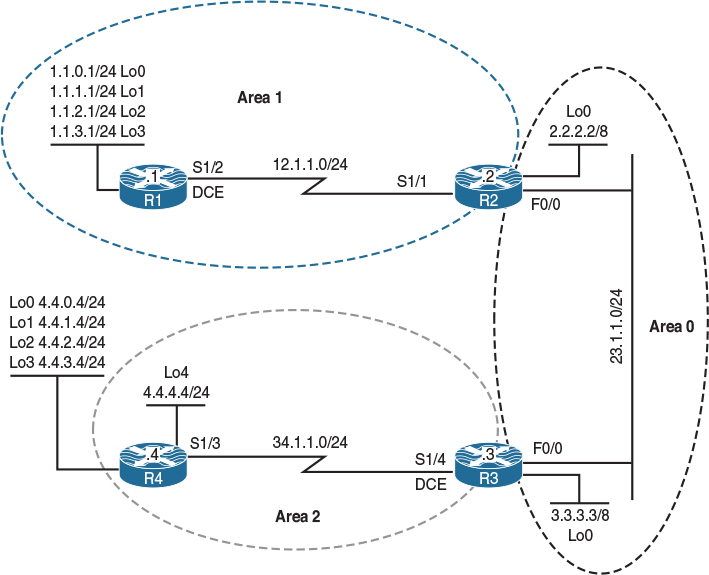
Figure 8-8 OSPF Summarization
Figure 8-8 illustrates the topology that will used in the following tasks.
Task 1
Configure R4 based on the following policy:
![]() R4 should run OSPF Area 2 on its loopback4 and s1/3 interfaces. This loopback interface should be advertised with its correct mask.
R4 should run OSPF Area 2 on its loopback4 and s1/3 interfaces. This loopback interface should be advertised with its correct mask.
![]() R4 should redistribute Lo0, Lo1, Lo2, and Lo3 in this routing domain.
R4 should redistribute Lo0, Lo1, Lo2, and Lo3 in this routing domain.
![]() R4’s router ID should be configured as 0.0.0.4.
R4’s router ID should be configured as 0.0.0.4.
On R4:
R4(config)# interface loopback 4
R4(config-if)# ip ospf network point-to-point
R4(config)# route-map tst
R4(config-route-map)# match interface lo0 lo1 lo2 lo3
R4(config)# router ospf 1
R4(config-router)# router-id 0.0.0.4
R4(config-router)# network 34.1.1.4 0.0.0.0 area 2
R4(config-router)# network 4.4.4.4 0.0.0.0 area 2
R4(config-router)# redistribute connected route-map tst subnets
Task 2
Configure R3 based on the following policy:
![]() R3 should run OSPF Area 0 on its loopback0 and f0/0 interfaces, and run OSPF Area 2 on its s1/4 interface. This loopback interface should be advertised with its correct mask.
R3 should run OSPF Area 0 on its loopback0 and f0/0 interfaces, and run OSPF Area 2 on its s1/4 interface. This loopback interface should be advertised with its correct mask.
![]() R3’s router ID should be configured as 0.0.0.3.
R3’s router ID should be configured as 0.0.0.3.
On R3:
R3(config)# interface loopback 0
R3(config-if)# ip ospf network point-to-point
R3(config)# router ospf 1
R3(config-router)# router-id 0.0.0.3
R3(config-router)# network 3.3.3.3 0.0.0.0 area 0
R3(config-router)# network 23.1.1.3 0.0.0.0 area 0
R3(config-router)# network 34.1.1.3 0.0.0.0 area 2
You should see the following console message:
%OSPF-5-ADJCHG: Process 1, Nbr 0.0.0.4 on Serial1/4 from LOADING to FULL,
Loading Done
Let’s verify the configuration:
On R3:
R3# show ip route ospf | begin Gate
Gateway of last resort is not set
4.0.0.0/24 is subnetted, 5 subnets
O E2 4.4.0.0 [110/20] via 34.1.1.4, 00:00:13, Serial1/4
O E2 4.4.1.0 [110/20] via 34.1.1.4, 00:00:13, Serial1/4
O E2 4.4.2.0 [110/20] via 34.1.1.4, 00:00:13, Serial1/4
O E2 4.4.3.0 [110/20] via 34.1.1.4, 00:00:13, Serial1/4
O 4.4.4.0 [110/782] via 34.1.1.4, 00:00:13, Serial1/4
Task 3
Configure R2 based on the following policy:
![]() R2 should advertise its loopback0 and f0/0 interfaces in Area 0 and its s1/1 interface in Area 1. This loopback interface should be advertised with its correct mask.
R2 should advertise its loopback0 and f0/0 interfaces in Area 0 and its s1/1 interface in Area 1. This loopback interface should be advertised with its correct mask.
![]() R2’s router ID should be configured as 0.0.0.2.
R2’s router ID should be configured as 0.0.0.2.
On R2:
R2(config)# interface loopback 0
R2(config-if)# ip ospf network point-to-point
R2(config)# router ospf 1
R2(config-router)# router-id 0.0.0.2
R2(config-router)# network 2.2.2.2 0.0.0.0 area 0
R2(config-router)# network 23.1.1.2 0.0.0.0 area 0
R2(config-router)# network 12.1.1.2 0.0.0.0 area 1
You should see the following console message:
%OSPF-5-ADJCHG: Process 1, Nbr 0.0.0.3 on FastEthernet0/0 from LOADING to FULL,
Loading Done
Let’s verify the configuration:
On R2:
R2# show ip route ospf | begin Gate
Gateway of last resort is not set
O 3.0.0.0/8 [110/2] via 23.1.1.3, 00:00:10, FastEthernet0/0
4.0.0.0/24 is subnetted, 5 subnets
O E2 4.4.0.0 [110/20] via 23.1.1.3, 00:00:10, FastEthernet0/0
O E2 4.4.1.0 [110/20] via 23.1.1.3, 00:00:10, FastEthernet0/0
O E2 4.4.2.0 [110/20] via 23.1.1.3, 00:00:10, FastEthernet0/0
O E2 4.4.3.0 [110/20] via 23.1.1.3, 00:00:10, FastEthernet0/0
O IA 4.4.4.0 [110/783] via 23.1.1.3, 00:00:10, FastEthernet0/0
34.0.0.0/24 is subnetted, 1 subnets
O IA 34.1.1.0 [110/782] via 23.1.1.3, 00:00:10, FastEthernet0/0
Task 4
Configure R1 based on the following policy:
![]() R1 should run OSPF Area 1 on all of its directly connected interfaces. You should use the minimum number of network statements to accomplish this task. The loopback interfaces must be advertised with their correct mask.
R1 should run OSPF Area 1 on all of its directly connected interfaces. You should use the minimum number of network statements to accomplish this task. The loopback interfaces must be advertised with their correct mask.
![]() R1’s router ID should be configured as 0.0.0.1.
R1’s router ID should be configured as 0.0.0.1.
On R1:
R1(config)# interface loopback 0
R1(config-if)# ip ospf network point-to-point
R1(config)# interface loopback 1
R1(config-if)# ip ospf network point-to-point
R1(config)# interface loopback 2
R1(config-if)# ip ospf network point-to-point
R1(config)# interface loopback 3
R1(config-if)# ip ospf network point-to-point
R1(config)# router ospf 1
R1(config-router)# router-id 0.0.0.1
R1(config-router)# network 0.0.0.0 0.0.0.0 area 1
You should see the following console message:
%OSPF-5-ADJCHG: Process 1, Nbr 0.0.0.2 on Serial1/2 from LOADING to FULL,
Loading Done
Let’s verify the configuration:
On R1:
R1# show ip route ospf | include O
Gateway of last resort is not set
O IA 2.0.0.0/8 [110/782] via 12.1.1.2, 00:00:08, Serial1/2
O IA 3.0.0.0/8 [110/783] via 12.1.1.2, 00:00:08, Serial1/2
4.0.0.0/24 is subnetted, 5 subnets
O E2 4.4.0.0 [110/20] via 12.1.1.2, 00:00:08, Serial1/2
O E2 4.4.1.0 [110/20] via 12.1.1.2, 00:00:08, Serial1/2
O E2 4.4.2.0 [110/20] via 12.1.1.2, 00:00:08, Serial1/2
O E2 4.4.3.0 [110/20] via 12.1.1.2, 00:00:08, Serial1/2
O IA 4.4.4.0 [110/1564] via 12.1.1.2, 00:00:08, Serial1/2
23.0.0.0/24 is subnetted, 1 subnets
O IA 23.1.1.0 [110/782] via 12.1.1.2, 00:00:08, Serial1/2
34.0.0.0/24 is subnetted, 1 subnets
O IA 34.1.1.0 [110/1563] via 12.1.1.2, 00:00:08, Serial1/2
On R2:
R2# show ip route ospf | begin Gate
Gateway of last resort is not set
1.0.0.0/24 is subnetted, 4 subnets
O 1.1.0.0 [110/782] via 12.1.1.1, 00:00:39, Serial1/1
O 1.1.1.0 [110/782] via 12.1.1.1, 00:00:39, Serial1/1
O 1.1.2.0 [110/782] via 12.1.1.1, 00:00:39, Serial1/1
O 1.1.3.0 [110/782] via 12.1.1.1, 00:00:39, Serial1/1
O 3.0.0.0/8 [110/2] via 23.1.1.3, 00:03:43, FastEthernet0/0
4.0.0.0/24 is subnetted, 5 subnets
O E2 4.4.0.0 [110/20] via 23.1.1.3, 00:03:43, FastEthernet0/0
O E2 4.4.1.0 [110/20] via 23.1.1.3, 00:03:43, FastEthernet0/0
O E2 4.4.2.0 [110/20] via 23.1.1.3, 00:03:43, FastEthernet0/0
O E2 4.4.3.0 [110/20] via 23.1.1.3, 00:03:43, FastEthernet0/0
O IA 4.4.4.0 [110/783] via 23.1.1.3, 00:03:43, FastEthernet0/0
34.0.0.0/24 is subnetted, 1 subnets
O IA 34.1.1.0 [110/782] via 23.1.1.3, 00:03:43, FastEthernet0/0
Task 5
Configure the appropriate router in Area 2 to summarize all the external (E2) routes.
In OSPF, summarization can be configured on two types of routers: an Area Border Router (ABR) and/or an Autonomous System Boundary Router (ASBR). OSPF intra-area routes can only be summarized on the ABRs, whereas the external (redistributed) routes can be summarized on the router that originates the external routes. This can be the ASBR or an ABR in a not-so-stubby-area (NSSA).
In an NSSA area, the ABR of that area receives the “N” routes, converts them to “E” routes, and then injects them into Area 0. In this case, because the ABR is the router that originates the E routes, the ABR can summarize the external routes (the E routes) and inject a single summary into Area 0.
When summarizing internal routes on an ABR, you must use the Area xx range command, where xx is the area ID where the specific routes were originated.
Summarization of external routes can be accomplished by using the summary-address router configuration mode command. In this case, because R4 is the router that originates Type-5 LSAs, summarization can only be performed on R4.
On R4:
R4(config)# router ospf 1
R4(config-router)# summary-address 4.4.0.0 255.255.252.0
Note Whenever summarization is performed on a given router, a discard route is auto-injected into the routing table for loop avoidance. This is a summary route pointing to the Null0 interface.
Let’s view the Null0 route for the summary:
On R4:
R4# show ip route | include Null0
O 4.4.0.0/22 is a summary, 00:09:31, Null0
Now let’s verify the configuration:
On R1:
R1# show ip route ospf | begin Gate
Gateway of last resort is not set
O IA 2.0.0.0/8 [110/782] via 12.1.1.2, 00:02:07, Serial1/2
O IA 3.0.0.0/8 [110/783] via 12.1.1.2, 00:02:07, Serial1/2
4.0.0.0/8 is variably subnetted, 2 subnets, 2 masks
O E2 4.4.0.0/22 [110/20] via 12.1.1.2, 00:00:30, Serial1/2
O IA 4.4.4.0/24 [110/1564] via 12.1.1.2, 00:02:07, Serial1/2
23.0.0.0/24 is subnetted, 1 subnets
O IA 23.1.1.0 [110/782] via 12.1.1.2, 00:02:07, Serial1/2
34.0.0.0/24 is subnetted, 1 subnets
O IA 34.1.1.0 [110/1563] via 12.1.1.2, 00:02:07, Serial1/2
Note The external routes are summarized.
Task 6
R4 should be configured to advertise the summary plus network 4.4.0.0/24.
This task can be accomplished in two different ways. First, you can add another summary-address command for network 4.4.0.0/24. Let’s test this method:
R4(config)# router ospf 1
R4(config-router)# summary-address 4.4.0.0 255.255.255.0
Now let’s verify the configuration:
On R1:
R1# show ip route ospf | begin Gate
Gateway of last resort is not set
O IA 2.0.0.0/8 [110/782] via 12.1.1.2, 00:06:39, Serial1/2
O IA 3.0.0.0/8 [110/783] via 12.1.1.2, 00:06:39, Serial1/2
4.0.0.0/8 is variably subnetted, 3 subnets, 2 masks
O E2 4.4.0.0/22 [110/20] via 12.1.1.2, 00:05:02, Serial1/2
O E2 4.4.0.0/24 [110/20] via 12.1.1.2, 00:00:46, Serial1/2
O IA 4.4.4.0/24 [110/1564] via 12.1.1.2, 00:06:39, Serial1/2
23.0.0.0/24 is subnetted, 1 subnets
O IA 23.1.1.0 [110/782] via 12.1.1.2, 00:06:39, Serial1/2
34.0.0.0/24 is subnetted, 1 subnets
O IA 34.1.1.0 [110/1563] via 12.1.1.2, 00:06:39, Serial1/2
Run the loopback0 interface in OSPF Area 2. Because the summary-address command only summarizes the external routes, if one of the specific routes is advertised as an intra-area route in Area 2, it won’t be summarized. Let’s verify this method.
First, we need to remove the second summary-address command:
On R4:
R4(config)# router ospf 1
R4(config-router)# no summary-address 4.4.0.0 255.255.255.0
Let’s run OSPF Area 2 on the loopback0 interface of R4, but we must advertise the loopback with its correct mask:
R4(config-router)# network 4.4.0.4 0.0.0.0 area 2
R4(config)# interface loopback 0
R4(config-if)# ip ospf network point-to-point
Let’s verify the configuration:
On R1:
R1# show ip route ospf | begin Gate
Gateway of last resort is not set
O IA 2.0.0.0/8 [110/782] via 12.1.1.2, 00:26:23, Serial1/2
O IA 3.0.0.0/8 [110/783] via 12.1.1.2, 00:26:23, Serial1/2
4.0.0.0/8 is variably subnetted, 3 subnets, 2 masks
O E2 4.4.0.0/22 [110/20] via 12.1.1.2, 00:24:46, Serial1/2
O IA 4.4.0.0/24 [110/1564] via 12.1.1.2, 00:02:40, Serial1/2
O IA 4.4.4.0/24 [110/1564] via 12.1.1.2, 00:26:23, Serial1/2
23.0.0.0/24 is subnetted, 1 subnets
O IA 23.1.1.0 [110/782] via 12.1.1.2, 00:26:23, Serial1/2
34.0.0.0/24 is subnetted, 1 subnets
O IA 34.1.1.0 [110/1563] via 12.1.1.2, 00:26:23, Serial1/2
Task 7
Configure the appropriate router in Area 1 to summarize networks 1.1.0.0/24, 1.1.1.0/24, 1.1.2.0/24, and 1.1.3.0/24 into the OSPF routing domain.
The routes that are identified in this task are originated by R1, and they can only be summarized by the ABR of Area 1 (in this topology, the ABR for Area 1 is R2).
On R2:
R2(config)# router ospf 1
R2(config-router)# area 1 range 1.1.0.0 255.255.252.0
Note Whenever summarization is performed on a given router, a discard route is auto-injected into the routing table for loop avoidance. This is a summary route pointing to the Null0 interface.
Let’s view the Null0 route for the summary:
On R2:
R2# show ip route ospf | include Null0
O 1.1.0.0/22 is a summary, 00:00:15, Null0
Now let’s verify the configuration:
On R3:
R3# show ip route ospf | begin Gate
Gateway of last resort is not set
1.0.0.0/22 is subnetted, 1 subnets
O IA 1.1.0.0 [110/783] via 23.1.1.2, 00:01:29, FastEthernet0/0
O 2.0.0.0/8 [110/2] via 23.1.1.2, 00:35:27, FastEthernet0/0
4.0.0.0/8 is variably subnetted, 3 subnets, 2 masks
O E2 4.4.0.0/22 [110/20] via 34.1.1.4, 00:29:45, Serial1/4
O 4.4.0.0/24 [110/782] via 34.1.1.4, 00:07:39, Serial1/4
O 4.4.4.0/24 [110/782] via 34.1.1.4, 00:37:30, Serial1/4
12.0.0.0/24 is subnetted, 1 subnets
O IA 12.1.1.0 [110/782] via 23.1.1.2, 00:34:16, FastEthernet0/0
Task 8
The routers should not install a Null 0 route in the routing table when summarization is performed. You should test two different methods to accomplish this task.
In OSPF, the discard route is installed in the routing table automatically whenever summarization is configured. There are two types of summary routes: internal and external.
When summarization is configured for intra-area routes, OSPF will auto-inject an internal discard route, and when summarization is configured for an external OSPF route, the OSPF process will create an external discard route. The discard routes are created to stop forwarding loops.
Here’s one way to remove the internal discard route:
On R2:
R2# show ip route ospf | include Null0
O 1.1.0.0/22 is a summary, 00:05:14, Null0
R2(config)# router ospf 1
R2(config-router)# no discard-route internal
Let’s verify the configuration:
On R2:
R2# show ip route ospf | include Null0
Let’s use another method, where we raise the administrative distance of this route to 255:
R2(config)# router ospf 1
R2(config-router)# discard-route internal
R2# show ip route ospf | include Null0
O 1.1.0.0/22 is a summary, 00:00:14, Null0
R2(config)# router ospf 1
R2(config-router)# discard-route internal 255
Let’s verify the configuration:
On R2:
R2# show ip route ospf | include Null0
Here’s one way to remove the external discard route:
On R4:
R4# show ip route ospf | include Null0
O 4.4.0.0/22 is a summary, 00:06:13, Null0
R4(config)# router ospf 1
R4(config-router)# no discard-route external
Let’s verify the configuration:
On R4:
R4# show ip route ospf | include Null0
To use the second method, just like we did for internal routes, we will raise the administrative distance to 255:
R4(config)# router ospf 1
R4(config-router)# discard-route external 255
Let’s verify the configuration:
On R4:
R4# show ip route ospf | include Null0
Task 9
Configure R2 to advertise 1.1.0.0/24 plus the summary route. You should demonstrate two different methods to accomplishing this task.
This task can be accomplished in two different ways. First, you can add another area range command for network 1.1.0.0/24. Let’s test this method:
Let’s verify the configuration:
On R4:
R4# show ip route ospf | begin Gate
Gateway of last resort is not set
1.0.0.0/8 is variably subnetted, 2 subnets, 2 masks
O IA 1.1.0.0/22 [110/1564] via 34.1.1.3, 00:07:37, Serial1/3
O IA 1.1.0.0/24 [110/1564] via 34.1.1.3, 00:00:34, Serial1/3
O IA 2.0.0.0/8 [110/783] via 34.1.1.3, 00:07:37, Serial1/3
O IA 3.0.0.0/8 [110/782] via 34.1.1.3, 00:07:37, Serial1/3
12.0.0.0/24 is subnetted, 1 subnets
O IA 12.1.1.0 [110/1563] via 34.1.1.3, 00:07:37, Serial1/3
23.0.0.0/24 is subnetted, 1 subnets
O IA 23.1.1.0 [110/782] via 34.1.1.3, 00:07:37, Serial1/3
Another way to accomplish the same task is to redistribute the loopback1 interface of R1.
Let’s remove the second area-range command:
R2(config)# router ospf 1
R2(config-router)# no area 1 range 1.1.0.0 255.255.255.0
Let’s verify the configuration:
On R4:
R4# show ip route ospf | begin Gate
Gateway of last resort is not set
1.0.0.0/22 is subnetted, 1 subnets
O IA 1.1.0.0 [110/1564] via 34.1.1.3, 00:12:45, Serial1/3
O IA 2.0.0.0/8 [110/783] via 34.1.1.3, 00:12:45, Serial1/3
O IA 3.0.0.0/8 [110/782] via 34.1.1.3, 00:12:45, Serial1/3
12.0.0.0/24 is subnetted, 1 subnets
O IA 12.1.1.0 [110/1563] via 34.1.1.3, 00:12:45, Serial1/3
23.0.0.0/24 is subnetted, 1 subnets
O IA 23.1.1.0 [110/782] via 34.1.1.3, 00:12:45, Serial1/3
You can see that the specific route (1.1.0.0/24) is no longer in the routing table of R4. Let’s redistribute that loopback interface into the OSPF routing domain on R1. Because the area-range command only summarizes the internal routes, if the loopback0 interface of R1 is redistributed into the OSPF routing domain, it won’t be summarized. Before this task can be accomplished, the network statement configured on R1 should be changed. The network statement of R1 states that the existing and future directly connected interfaces should be advertised in Area 1. Let’s have a look at the way OSPF is configured:
R1# Show run | section router ospf
router ospf 1
router-id 0.0.0.1
network 0.0.0.0 255.255.255.255 area 1
With the preceding configuration, even if the loopback0 interface is redistributed into the OSPF routing domain, it will still be advertised as an internal route. Let’s redistribute:
R1(config)# route-map tst
R1(config-route-map)# match interface loopback 0
R1(config)# router ospf 1
R1(config-router)# redistribute connected route-map tst subnets
Let’s verify the configuration:
On R4:
R4# show ip route ospf | begin Gate
Gateway of last resort is not set
1.0.0.0/22 is subnetted, 1 subnets
O IA 1.1.0.0 [110/1564] via 34.1.1.3, 00:22:06, Serial1/3
O IA 2.0.0.0/8 [110/783] via 34.1.1.3, 00:22:06, Serial1/3
O IA 3.0.0.0/8 [110/782] via 34.1.1.3, 00:22:06, Serial1/3
12.0.0.0/24 is subnetted, 1 subnets
O IA 12.1.1.0 [110/1563] via 34.1.1.3, 00:22:06, Serial1/3
23.0.0.0/24 is subnetted, 1 subnets
O IA 23.1.1.0 [110/782] via 34.1.1.3, 00:22:06, Serial1/3
The output of the preceding show command reveals that the loopback0 interface of R1 is summarized. Let’s reconfigure the network statement on R1 and verify again:
R1(config)# router ospf 1
R1(config-router)# network 1.1.1.1 0.0.0.0 area 1
R1(config-router)# network 1.1.2.1 0.0.0.0 area 1
R1(config-router)# network 1.1.3.1 0.0.0.0 area 1
R1(config-router)# network 12.1.1.1 0.0.0.0 area 1
Now let’s remove the original network statement:
R1(config-router)# no network 0.0.0.0 0.0.0.0 area 1
Let’s view the OSPF configuration after this change:
R1# show run | section router ospf
router ospf 1
router-id 0.0.0.1
redistribute connected subnets route-map tst
network 1.1.1.1 0.0.0.0 area 1
network 1.1.2.1 0.0.0.0 area 1
network 1.1.3.1 0.0.0.0 area 1
network 12.1.1.1 0.0.0.0 area 1
Now let’s verify the configuration:
On R4:
R4# show ip route ospf | be Gate
Gateway of last resort is not set
1.0.0.0/8 is variably subnetted, 2 subnets, 2 masks
O IA 1.1.0.0/22 [110/1564] via 34.1.1.3, 00:25:38, Serial1/3
O E2 1.1.0.0/24 [110/20] via 34.1.1.3, 00:01:12, Serial1/3
O IA 2.0.0.0/8 [110/783] via 34.1.1.3, 00:25:38, Serial1/3
O IA 3.0.0.0/8 [110/782] via 34.1.1.3, 00:25:38, Serial1/3
12.0.0.0/24 is subnetted, 1 subnets
O IA 12.1.1.0 [110/1563] via 34.1.1.3, 00:25:38, Serial1/3
23.0.0.0/24 is subnetted, 1 subnets
O IA 23.1.1.0 [110/782] via 34.1.1.3, 00:25:38, Serial1/3
Erase the startup config and reload the routers before proceeding to the next lab.
Lab 8-8: OSPF Filtering
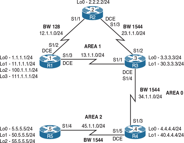
Figure 8-9 OSPF Filtering
Figure 8-9 illustrates the topology that will used in the following tasks.
Task 1
Configure R1 and R2’s directly connected interfaces, and configure R3’s serial connections to R2 and R1 in Area 1. Configure 0.0.0.1, 0.0.0.2, and 0.0.0.3 to be the OSPF RIDs of R1, R2, and R3, respectively.
On R1:
R1(config)# router ospf 1
R1(config-router)# router-id 0.0.0.1
R1(config-router)# network 12.1.1.1 0.0.0.0 area 1
R1(config-router)# network 13.1.1.1 0.0.0.0 area 1
R1(config-router)# network 1.1.1.1 0.0.0.0 area 1
R1(config-router)# network 11.1.1.1 0.0.0.0 area 1
R1(config-router)# network 100.1.1.1 0.0.0.0 area 1
R1(config-router)# network 111.1.1.1 0.0.0.0 area 1
On R2:
R2(config)# router ospf 1
R2(config-router)# router-id 0.0.0.2
R2(config-router)# network 12.1.1.2 0.0.0.0 area 1
R2(config-router)# network 23.1.1.2 0.0.0.0 area 1
R2(config-router)# network 2.2.2.2 0.0.0.0 area 1
You should see the following console message:
%OSPF-5-ADJCHG: Process 1, Nbr 0.0.0.1 on Serial1/1 from LOADING to FULL,
Loading Done
On R3:
R3(config)# router ospf 1
R3(config-router)# router-id 0.0.0.3
R3(config-router)# network 23.1.1.3 0.0.0.0 area 1
R3(config-router)# network 13.1.1.3 0.0.0.0 area 1
You should also see these console messages:
%OSPF-5-ADJCHG: Process 1, Nbr 0.0.0.2 on Serial1/2 from LOADING to FULL,
Loading Done
%OSPF-5-ADJCHG: Process 1, Nbr 0.0.0.1 on Serial1/1 from LOADING to FULL,
Loading Done
Let’s verify the configuration:
On R1:
R1# show ip route ospf | begin Gate
Gateway of last resort is not set
2.0.0.0/32 is subnetted, 1 subnets
O 2.2.2.2 [110/129] via 13.1.1.3, 00:00:29, Serial1/3
23.0.0.0/24 is subnetted, 1 subnets
O 23.1.1.0 [110/128] via 13.1.1.3, 00:00:29, Serial1/3
On R3:
R3# show ip route ospf | begin Gate
Gateway of last resort is not set
1.0.0.0/32 is subnetted, 1 subnets
O 1.1.1.1 [110/65] via 13.1.1.1, 00:01:23, Serial1/1
2.0.0.0/32 is subnetted, 1 subnets
O 2.2.2.2 [110/65] via 23.1.1.2, 00:01:33, Serial1/2
11.0.0.0/32 is subnetted, 1 subnets
O 11.1.1.1 [110/65] via 13.1.1.1, 00:01:23, Serial1/1
12.0.0.0/24 is subnetted, 1 subnets
O 12.1.1.0 [110/845] via 23.1.1.2, 00:01:33, Serial1/2
[110/845] via 13.1.1.1, 00:01:23, Serial1/1
100.0.0.0/32 is subnetted, 1 subnets
O 100.1.1.1 [110/65] via 13.1.1.1, 00:01:23, Serial1/1
111.0.0.0/32 is subnetted, 1 subnets
O 111.1.1.1 [110/65] via 13.1.1.1, 00:01:23, Serial1/1
On R2:
R2# show ip route ospf | begin Gate
Gateway of last resort is not set
1.0.0.0/32 is subnetted, 1 subnets
O 1.1.1.1 [110/129] via 23.1.1.3, 00:02:04, Serial1/3
11.0.0.0/32 is subnetted, 1 subnets
O 11.1.1.1 [110/129] via 23.1.1.3, 00:02:04, Serial1/3
13.0.0.0/24 is subnetted, 1 subnets
O 13.1.1.0 [110/128] via 23.1.1.3, 00:02:04, Serial1/3
100.0.0.0/32 is subnetted, 1 subnets
O 100.1.1.1 [110/129] via 23.1.1.3, 00:02:04, Serial1/3
111.0.0.0/32 is subnetted, 1 subnets
O 111.1.1.1 [110/129] via 23.1.1.3, 00:02:04, Serial1/3
Task 2
Configure the serial connection between R3 and R4 in Area 0. R4’s OSPF RID should be set to 0.0.0.4.
On R4:
R4(config)# router ospf 1
R4(config-router)# router-id 0.0.0.4
R4(config-router)# network 34.1.1.4 0.0.0.0 area 0
You should see the following console message:
%OSPF-5-ADJCHG: Process 1, Nbr 0.0.0.3 on Serial1/3 from LOADING to FULL,
Loading Done
Let’s verify the configuration:
On R4:
R4# show ip route ospf | begin Gate
Gateway of last resort is not set
1.0.0.0/32 is subnetted, 1 subnets
O IA 1.1.1.1 [110/129] via 34.1.1.3, 00:00:38, Serial1/3
2.0.0.0/32 is subnetted, 1 subnets
O IA 2.2.2.2 [110/129] via 34.1.1.3, 00:00:38, Serial1/3
11.0.0.0/32 is subnetted, 1 subnets
O IA 11.1.1.1 [110/129] via 34.1.1.3, 00:00:38, Serial1/3
12.0.0.0/24 is subnetted, 1 subnets
O IA 12.1.1.0 [110/909] via 34.1.1.3, 00:00:38, Serial1/3
13.0.0.0/24 is subnetted, 1 subnets
O IA 13.1.1.0 [110/128] via 34.1.1.3, 00:00:38, Serial1/3
23.0.0.0/24 is subnetted, 1 subnets
O IA 23.1.1.0 [110/128] via 34.1.1.3, 00:00:38, Serial1/3
100.0.0.0/32 is subnetted, 1 subnets
O IA 100.1.1.1 [110/129] via 34.1.1.3, 00:00:38, Serial1/3
111.0.0.0/32 is subnetted, 1 subnets
O IA 111.1.1.1 [110/129] via 34.1.1.3, 00:00:38, Serial1/3
Task 3
Configure the serial connection between R4 and R5 in Area 2. R5’s OSPF RID should be set to 0.0.0.5.
On R4:
R4(config)# router ospf 1
R4(config-router)# network 45.1.1.4 0.0.0.0 area 2
On R5:
R5(config)# router ospf 1
R5(config-router)# router-id 0.0.0.5
R5(config-router)# network 45.1.1.5 0.0.0.0 area 2
You should see the following console message:
%OSPF-5-ADJCHG: Process 1, Nbr 0.0.0.4 on Serial1/4 from LOADING to FULL,
Loading Done
Let’s verify the configuration:
On R5:
R5# show ip route ospf | begin Gate
Gateway of last resort is not set
1.0.0.0/32 is subnetted, 1 subnets
O IA 1.1.1.1 [110/193] via 45.1.1.4, 00:00:43, Serial1/4
2.0.0.0/32 is subnetted, 1 subnets
O IA 2.2.2.2 [110/193] via 45.1.1.4, 00:00:43, Serial1/4
11.0.0.0/32 is subnetted, 1 subnets
O IA 11.1.1.1 [110/193] via 45.1.1.4, 00:00:43, Serial1/4
12.0.0.0/24 is subnetted, 1 subnets
O IA 12.1.1.0 [110/973] via 45.1.1.4, 00:00:43, Serial1/4
13.0.0.0/24 is subnetted, 1 subnets
O IA 13.1.1.0 [110/192] via 45.1.1.4, 00:00:43, Serial1/4
23.0.0.0/24 is subnetted, 1 subnets
O IA 23.1.1.0 [110/192] via 45.1.1.4, 00:00:43, Serial1/4
34.0.0.0/24 is subnetted, 1 subnets
O IA 34.1.1.0 [110/128] via 45.1.1.4, 00:00:43, Serial1/4
100.0.0.0/32 is subnetted, 1 subnets
O IA 100.1.1.1 [110/193] via 45.1.1.4, 00:00:43, Serial1/4
111.0.0.0/32 is subnetted, 1 subnets
O IA 111.1.1.1 [110/193] via 45.1.1.4, 00:00:43, Serial1/4
Task 4
Configure the loopback interfaces of R1 and R2 with their correct mask.
On R1:
R1(config)# interface range loopback 0 - 3
R1(config-if)# ip ospf network point-to-point
On R2:
R2(config)# interface lo0
R2(config-if)# ip ospf network point-to-point
Let’s verify the configuration:
On R5:
R5# show ip route ospf | begin Gate
Gateway of last resort is not set
1.0.0.0/24 is subnetted, 1 subnets
O IA 1.1.1.0 [110/193] via 45.1.1.4, 00:00:37, Serial1/4
2.0.0.0/24 is subnetted, 1 subnets
O IA 2.2.2.0 [110/193] via 45.1.1.4, 00:00:20, Serial1/4
11.0.0.0/24 is subnetted, 1 subnets
O IA 11.1.1.0 [110/193] via 45.1.1.4, 00:00:37, Serial1/4
12.0.0.0/24 is subnetted, 1 subnets
O IA 12.1.1.0 [110/973] via 45.1.1.4, 00:02:26, Serial1/4
13.0.0.0/24 is subnetted, 1 subnets
O IA 13.1.1.0 [110/192] via 45.1.1.4, 00:02:26, Serial1/4
23.0.0.0/24 is subnetted, 1 subnets
O IA 23.1.1.0 [110/192] via 45.1.1.4, 00:02:26, Serial1/4
34.0.0.0/24 is subnetted, 1 subnets
O IA 34.1.1.0 [110/128] via 45.1.1.4, 00:02:26, Serial1/4
100.0.0.0/24 is subnetted, 1 subnets
O IA 100.1.1.0 [110/193] via 45.1.1.4, 00:00:37, Serial1/4
111.0.0.0/24 is subnetted, 1 subnets
O IA 111.1.1.0 [110/193] via 45.1.1.4, 00:00:37, Serial1/4
Task 5
Configure R2 to filter network 1.1.1.0/24 from its routing table. Ensure that R3, R4, and R5 have full reachability to this network. You should use an ip prefix-list to accomplish this task.
In this case, the following solution only affects the router it’s configured on:
On R2:
R2(config)# ip prefix-list TST seq 5 deny 1.1.1.0/24
R2(config)# ip prefix-list TST seq 10 permit 0.0.0.0/0 le 32
R2(config)# router ospf 1
R2(config-router)# distribute-list Prefix TST in
Let’s verify the configuration:
On R2:
R2# show ip route 1.1.1.0
% network not in table
Note that the distribute-list in router configuration mode command can be used when filtering any route on any given router. This command only filters the prefix(es) from the local router’s routing table and not the database. The output of the following show command reveals that R2 still has the prefix in its database:
R2# show ip ospf database router adv-router 0.0.0.1
OSPF router with ID (0.0.0.2) (Process ID 1)
router Link States (Area 1)
LS age: 383
Options: (No TOS-capability, DC)
LS Type: router Links
Link State ID: 0.0.0.1
Advertising Router: 0.0.0.1
LS Seq Number: 80000009
Checksum: 0xD11D
Length: 120
Number of Links: 8
Link connected to: a Stub Network
(Link ID) Network/subnet number: 1.1.1.0
(Link Data) network Mask: 255.255.255.0
Number of MTID metrics: 0
TOS 0 Metrics: 1
(The rest of the output is omitted for brevity)
Let’s verify and test the configuration:
On R3:
R3# ping 1.1.1.1
Type escape sequence to abort.
Sending 5, 100-byte ICMP Echos to 1.1.1.1, timeout is 2 seconds:
!!!!!
Success rate is 100 percent (5/5), round-trip min/avg/max = 28/28/32 ms
On R4:
R4# ping 1.1.1.1
Type escape sequence to abort.
Sending 5, 100-byte ICMP Echos to 1.1.1.1, timeout is 2 seconds:
!!!!!
Success rate is 100 percent (5/5), round-trip min/avg/max = 80/81/84 ms
On R5:
R5# ping 1.1.1.1
Type escape sequence to abort.
Sending 5, 100-byte ICMP Echos to 1.1.1.1, timeout is 2 seconds:
!!!!!
Success rate is 100 percent (5/5), round-trip min/avg/max = 128/130/132 ms
Task 6
Configure filtering on the appropriate router(s) such that the existing and future routers in Area 2 do not see network 11.1.1.0/24 in their routing table and/or database.
The following method only works for filtering Type-3 LSAs. You must remember the following two points:
![]() LSA Type-3 filtering can only be configured on the ABR(s).
LSA Type-3 filtering can only be configured on the ABR(s).
![]() You must use a prefix list.
You must use a prefix list.
The first step is to configure a prefix list to deny network 11.1.1.0/24 and permit everything else:
On R4:
R4(config)# ip prefix-list TST seq 5 deny 11.1.1.0/24
R4(config)# ip prefix-list TST seq 10 permit 0.0.0.0/0 le 32
The prefix list can reference Area 0 or Area 2. If it references Area 0, the direction must be “out,” meaning that you are filtering the prefix out of Area 0. In this case, it will affect the existing and future downstream areas that connect to Area 0.
The prefix can also reference Area 2. If it references Area 2, the direction must be “in,” meaning that you are filtering the prefix from getting into Area 2.
In this case, Area 2 is referenced in the command:
R4(config)# router ospf 1
R4(config-router)# area 2 filter-list prefix TST in
Let’s verify the configuration:
On R5:
R5# show ip route 11.1.1.0
% network not in table
The preceding show command reveals that R5 does not have the route in its routing table, and the following command verifies that R5 does not have the prefix in its database:
R5# show ip ospf database summary 11.1.1.0
OSPF router with ID (0.0.0.5) (Process ID 1)
On R4:
R4# show ip route 11.1.1.0
Routing entry for 11.1.1.0/24
Known via "ospf 1", distance 110, metric 129, type inter area
Last update from 34.1.1.3 on Serial1/3, 00:21:56 ago
Routing Descriptor Blocks:
* 34.1.1.3, from 0.0.0.3, 00:21:56 ago, via Serial1/3
Route metric is 129, traffic share count is 1
Note Even though the output of the preceding show command reveals that network 11.1.1.0/24 is in R4’s routing table, the output of the following show command clearly shows that it’s in the database of Area 0 and not in the database that belongs to Area 2:
R4# show ip ospf database summary 11.1.1.0
OSPF router with ID (0.0.0.4) (Process ID 1)
Summary Net Link States (Area 0)
Routing Bit Set on this LSA in topology Base with MTID 0
LS age: 1369
Options: (No TOS-capability, DC, Upward)
LS Type: Summary Links(Network)
Link State ID: 11.1.1.0 (summary network Number)
Advertising Router: 0.0.0.3
LS Seq Number: 80000001
Checksum: 0x5D8E
Length: 28
network Mask: /24
MTID: 0 Metric: 65
Let’s check another prefix, such as 1.1.1.0/24, and see the difference. This prefix should be in the database of Area 0 and Area 2:
R4# show ip ospf database summary 1.1.1.0
OSPF router with ID (0.0.0.4) (Process ID 1)
Summary Net Link States (Area 0)
Routing Bit Set on this LSA in topology Base with MTID 0
LS age: 1406
Options: (No TOS-capability, DC, Upward)
LS Type: Summary Links(Network)
Link State ID: 1.1.1.0 (summary network Number)
Advertising Router: 0.0.0.3
LS Seq Number: 80000001
Checksum: 0xDF16
Length: 28
network Mask: /24
MTID: 0 Metric: 65
Summary Net Link States (Area 2)
LS age: 1405
Options: (No TOS-capability, DC, Upward)
LS Type: Summary Links(Network)
Link State ID: 1.1.1.0 (summary network Number)
Advertising Router: 0.0.0.4
LS Seq Number: 80000001
Checksum: 0x5C58
Length: 28
network Mask: /24
MTID: 0 Metric: 129
You can see that from R4’s perspective, network 1.1.1.0/24 shows up in the database of Areas 0 and 2. From Area 0’s perspective, the cost is 65; from Area 2’s perspective, the cost is 129.
Task 7
Configure the appropriate router such that the routers in Area 0 do not see network 11.1.1.0/24 in their routing table or link state database. You should use the same solution as the one in the previous task, but it should be implemented in the outbound direction.
In the previous task, this network (11.1.1.0/24) was filtered from getting into Area 2. Now, you need to filter it from getting into Area 0. Once this filtering is accomplished, any existing and future area(s) downstream to Area 0 will be affected.
On R4:
R4# show ip route 11.1.1.0
Routing entry for 11.1.1.0/24
Known via "ospf 1", distance 110, metric 129, type inter area
Last update from 34.1.1.3 on Serial1/3, 00:33:58 ago
Routing Descriptor Blocks:
* 34.1.1.3, from 0.0.0.3, 00:33:58 ago, via Serial1/3
Route metric is 129, traffic share count is 1
On R3:
R3(config)# ip prefix-list TST seq 5 deny 11.1.1.0/24
R3(config)# ip prefix-list TST seq 10 permit 0.0.0.0/0 le 32
R3(config)# router ospf 1
R3(config-router)# area 1 filter-list prefix TST out
Let’s verify the configuration. The output of the following command reveals that prefix 11.1.1.0/24 is no longer in the routing table of R4:
On R4:
R4# show ip route 11.1.1.0
% network not in table
Note The prefix is still in the routing table of R3, where the filtering was performed, but the prefix is in the routing table of R3 as a route from Area 1 (an intra-area route) and not a prefix from Area 0 (from Area 0’s perspective this prefix is an inter-area route).
On R3:
R3# show ip route 11.1.1.0
Routing entry for 11.1.1.0/24
Known via "ospf 1", distance 110, metric 65, type intra area
Last update from 13.1.1.1 on Serial1/1, 00:37:55 ago
Routing Descriptor Blocks:
* 13.1.1.1, from 0.0.0.1, 00:37:55 ago, via Serial1/1
Route metric is 65, traffic share count is 1
On R3:
R3# show ip ospf database summary 11.1.1.0
OSPF router with ID (0.0.0.3) (Process ID 1)
Note that the output of the preceding show command reveals that network 11.1.1.0 /24 is not in Area 0. If it was in Area 0, it would have been in the link state database of this router as a summary LSA or Type-3 LSA. However, the following show command reveals that the prefix is in Area 1 as a router LSA or Type-1 LSA.
R3# show ip ospf database router | include Area 1|_11.1.1.0
Router Link States (Area 1)
(Link ID) Network/subnet number: 11.1.1.0
Task 8
Configure the appropriate router(s) to filter network 111.1.1.0/24 such that the routers in Area 0 or Area 2 do not have this network in their routing table or database. Use the minimum number of commands to accomplish this task.
The output of the following show command verifies that network 111.1.1.0/24 is in the database of R3 belonging to Area 1 as a router LSA or Type-1 LSA:
On R3:
R3# show ip ospf database router | Include Area 1|_111.1.1.0
router Link States (Area 1)
(Link ID) Network/subnet number: 111.1.1.0
The output of the following show command reveals that prefix 111.1.1.0/24 is also in the database of R3 as a summary LSA or Type-3 LSA, but from Area 0’s perspective:
R3# show ip ospf database summary 111.1.1.0
OSPF router with ID (0.0.0.3) (Process ID 1)
Summary Net Link States (Area 0)
LS age: 120
Options: (No TOS-capability, DC, Upward)
LS Type: Summary Links(Network)
Link State ID: 111.1.1.0 (summary network Number)
Advertising Router: 0.0.0.3
LS Seq Number: 80000003
Checksum: 0x4045
Length: 28
network Mask: /24
MTID: 0 Metric: 65
The following command reveals that prefix 111.1.1.0/24 is in the routing table of R3 as an intra-area route:
R3# show ip route ospf | include 111.1.1.0
O 111.1.1.0 [110/65] via 13.1.1.1, 01:07:30, Serial1/1
R3# show ip ospf route | Inc 111.1.1.0/24
*> 111.1.1.0/24, Intra, cost 65, area 1
The following OSPF filtering mechanism works only on intra-area routes. It instructs the router not to generate a Type-3 LSA for this prefix.
On R3:
R3(config)# router ospf 1
R3(config-router)# area 1 range 111.1.1.0 255.255.255.0 not-advertise
Note that, as stated earlier, the area range not-advertise command stops the generation of Type-3 LSAs, and this is why you see the prefix in the routing table of R3 as an intra-area route:
R3# show ip route 111.1.1.0
Routing entry for 111.1.1.0/24
Known via "ospf 1", distance 110, metric 65, type intra area
Last update from 13.1.1.1 on Serial1/1, 00:00:27 ago
Routing Descriptor Blocks:
* 13.1.1.1, from 0.0.0.1, 00:00:27 ago, via Serial1/1
Route metric is 65, traffic share count is 1
The prefix is no longer in the database of R3 as Type-3 LSAs, which means that the routers in Area 0 or any other area downstream of Area 0 will not have this prefix in their routing table or their link state database.
R3# show ip ospf database summary 111.1.1.0
OSPF router with ID (0.0.0.3) (Process ID 1)
R3# show ip ospf database router | Inc Area 1|_111.1.1.0
router Link States (Area 1)
(Link ID) Network/subnet number: 111.1.1.0
On R4 or R5:
Rx# show ip route 111.1.1.0
% network not in table
Task 9
Configure the appropriate routers such that none of the routers except R1 can see network 100.1.1.0/24 in their routing table; do not stop advertising this network. You should use a distribute list to accomplish this task.
You should always display the existing access lists and distribute lists before configuring one:
On R2:
R2# Show ip prefix-list
ip prefix-list TST: 2 entries
seq 5 deny 1.1.1.0/24
seq 10 permit 0.0.0.0/0 le 32
R2# show run | section router ospf 1
router ospf 1
router-id 0.0.0.2
log-adjacency-changes
network 2.2.2.2 0.0.0.0 area 1
network 12.1.1.2 0.0.0.0 area 1
network 23.1.1.2 0.0.0.0 area 1
distribute-list prefix TST in
Note The preceding show command verifies that there is already a distribute-list configured in the router configuration mode; therefore, you should try to modify the existing prefix-list that is applied by the existing distribute-list.
R2(config)# ip prefix-list TST seq 7 deny 100.1.1.0/24
Let’s view the prefix list after this addition:
On R2:
R2# show run | Include ip pref
ip prefix-list TST seq 5 deny 1.1.1.0/24
ip prefix-list TST seq 7 deny 100.1.1.0/24
ip prefix-list TST seq 10 permit 0.0.0.0/0 le 32
Now let’s verify the configuration:
On R2:
R2# show ip route 100.1.1.0
% network not in table
Let’s check R3:
On R3:
R3# show ip prefix-list
ip prefix-list TST: 2 entries
seq 5 deny 11.1.1.0/24
seq 10 permit 0.0.0.0/0 le 32
R3# show run | section ospf
router ospf 1
router-id 0.0.0.3
area 1 range 111.1.1.0 255.255.255.0 not-advertise
area 1 filter-list prefix TST out
network 13.1.1.3 0.0.0.0 area 1
network 23.1.1.3 0.0.0.0 area 1
network 34.1.1.3 0.0.0.0 area 0
R3# show ip route | Include 100.1.1.0
O 100.1.1.0 [110/65] via 13.1.1.1, 00:08:38, Serial1/1
Let’s configure R3:
R3(config)# ip prefix-list NET seq 5 deny 100.1.1.0/24
R3(config)# ip prefix-list NET seq 10 permit 0.0.0.0/0 LE 32
R3(config)# router ospf 1
R3(config-router)# distribute-list prefix NET in
Now let’s verify the configuration:
On R3:
R3# show ip route ospf | Include 100.1.1.0
On R4, the distance command can be used to reference network 100.1.1.0/24 in access-list 1, and the distance command sets the AD of the network referenced in access-list 1 to 255 sourcing from R3 (0.0.0.3 0.0.0.0); AD of 255 is unreachable and won’t be injected into the routing table:
On R4:
R4(config)# access-list 1 permit 100.1.1.0 0.0.0.255
R4(config)# router ospf 1
R4(config-router)# distance 255 0.0.0.3 0.0.0.0 1
On R5:
R5# show ip route 100.1.1.0 255.255.255.0
% network not in table
R5# show ip ospf database summary 100.1.1.0
OSPF router with ID (0.0.0.5) (Process ID 1)
Note that the preceding solution utilizes the behavior of OSPF when prefixes are advertised from Area 0 into a non-zero area; when inter-area prefixes are advertised from Area 0 into other areas, the behavior is like an internal redistribution. Basically, if R4 does not have the route in its routing table, it will not redistribute the route into Area 2; therefore, R5 or any other router in Area 2 will not see the prefix(es) in its routing table or database.
Task 10
Configure R5 to redistribute the loopback0, 1, and 2 interfaces into the OSPF routing domain using the default cost.
On R5:
R5(config)# route-map TST permit 10
R5(config-route-map)# match interface lo0 lo1 lo2
R5(config)# router ospf 1
R5(config-router)# redistribute connected subnets route-map TST
Let’s verify the configuration:
On R4:
R4# show ip route ospf | Include E2
E1 - OSPF external type 1, E2 - OSPF external type 2
O E2 5.5.5.0 [110/20] via 45.1.1.5, 00:00:08, Serial1/5
O E2 50.5.5.0 [110/20] via 45.1.1.5, 00:00:08, Serial1/5
O E2 55.5.5.0 [110/20] via 45.1.1.5, 00:00:08, Serial1/5
Task 11
Configure the appropriate router such that none of the routers except R5 can see network 5.5.5.0/24 in their routing table.
On R5:
R5(config)# ip prefix-list NET seq 5 deny 5.5.5.0/24
R5(config)# ip prefix-list NET seq 10 permit 0.0.0.0/0 LE 32
R5(config)# router ospf 1
R5(config-router)# distribute-list prefix NET OUT
Let’s verify the configuration:
On R4:
R4# show ip route ospf | Include E2
E1 - OSPF external type 1, E2 - OSPF external type 2
O E2 50.5.5.0 [110/20] via 45.1.1.5, 00:02:07, Serial1/5
O E2 55.5.5.0 [110/20] via 45.1.1.5, 00:02:07, Serial1/5
On R1:
R1# show ip route ospf | Include E2
E1 - OSPF external type 1, E2 - OSPF external type 2
O E2 50.5.5.0 [110/20] via 13.1.1.3, 00:02:55, Serial1/3
O E2 55.5.5.0 [110/20] via 13.1.1.3, 00:02:55, Serial1/3
Note that this is the only scenario where the distribute-list OUT command works in OSPF. This command must be configured on the ASBR; otherwise, it will not have any effect whatsoever. This command filters external routes.
R5# show ip ospf database external | Include 5
OSPF router with ID (0.0.0.5) (Process ID 1)
Type-5 AS External Link States
Link State ID: 50.5.5.0 (External network Number )
Advertising Router: 0.0.0.5
Checksum: 0xC995
Link State ID: 55.5.5.0 (External network Number )
Advertising Router: 0.0.0.5
Task 12
Configure the appropriate router such that none of the routers except R5 can see network 50.5.5.0/24 in their routing table or database. You should not use the solution that was implemented in the previous task.
The following command is used to filter the external routes (“E” and/or “N”). This command must be configured on an ASBR or the router that originated the external route(s), and when configured, it filters the specified prefix from the OSPF link state database.
On R5:
R5(config)# router ospf 1
R5(config-router)# summary-address 50.5.5.0 255.255.255.0 not-advertise
The following show command reveals that network 50.5.5.0/24 is not in the link state database of R5:
R5# show ip ospf database external | Include 5
OSPF router with ID (0.0.0.5) (Process ID 1)
Type-5 AS External Link States
Link State ID: 55.5.5.0 (External network Number )
Advertising Router: 0.0.0.5
Let’s verify the configuration:
On R4:
R4# show ip route 50.5.5.0
% network not in table
On R1:
R1# show ip route 50.5.5.0
% network not in table
Task 13
Configure the appropriate router such that R1 does not have network 55.5.5.0/24 in its routing table.
Let’s view R1’s existing routing table:
On R1:
R1# show ip route 55.5.5.0
Routing entry for 55.5.5.0/24
Known via "ospf 1", distance 110, metric 20, type extern 2, forward metric 192
Last update from 13.1.1.3 on Serial1/3, 00:10:17 ago
Routing Descriptor Blocks:
* 13.1.1.3, from 0.0.0.5, 00:10:17 ago, via Serial1/3
Route metric is 20, traffic share count is 1
Note There is no access-list or ip prefix-list configured on this router:
R1# show access-list
R1# show ip prefix-list
R1(config)# ip prefix-list NET seq 5 deny 55.5.5.0/24
R1(config)# ip prefix-list NET seq 10 permit 0.0.0.0/0 LE 32
R1(config)# router ospf 1
R1(config-router)# distribute-list prefix NET in
Let’s verify the configuration:
On R1:
R1# show ip route 55.5.5.0
% network not in table
Task 14
Remove any filtering used in the previous tasks. If this configuration is performed successfully, all the routers in this routing domain should have every route advertised and redistributed in this lab.
On R1:
R1(config)# No ip prefix NET
R1(config)# router ospf 1
R1(config-router)# No distribute-list prefix NET in
R1# Show run | section router ospf
router ospf 1
router-id 0.0.0.1
network 1.1.1.1 0.0.0.0 area 1
network 11.1.1.1 0.0.0.0 area 1
network 12.1.1.1 0.0.0.0 area 1
network 13.1.1.1 0.0.0.0 area 1
network 100.1.1.1 0.0.0.0 area 1
network 111.1.1.1 0.0.0.0 area 1
On R2:
R2(config)# No ip prefix-list TST
R2(config)# router ospf 1
R2(config-router)# No distribute-list prefix TST in
R2# show run | section ospf
ip ospf network point-to-point
router ospf 1
router-id 0.0.0.2
network 2.2.2.2 0.0.0.0 area 1
network 12.1.1.2 0.0.0.0 area 1
network 23.1.1.2 0.0.0.0 area 1
On R3:
R3(config)# No ip prefix-list NET
R3(config)# No ip prefix-list TST
R3(config)# router ospf 1
R3(config-router)# No area 1 range 111.1.1.0 255.255.255.0 not-advertise
R3(config-router)# No distribute-list prefix NET in
R3(config-router)# No area 1 filter-list prefix TST out
R3# Show run | section ospf
router ospf 1
router-id 0.0.0.3
network 13.1.1.3 0.0.0.0 area 1
network 23.1.1.3 0.0.0.0 area 1
network 34.1.1.3 0.0.0.0 area 0
On R4:
R4(config)# No ip prefix-list TST
R4(config)# No access-list 1
R4(config)# router ospf 1
R4(config-router)# No distance 255 0.0.0.3 0.0.0.0 1
R4(config-router)# No area 2 filter-list prefix TST in
R4# show run | section ospf
router ospf 1
router-id 0.0.0.4
network 34.1.1.4 0.0.0.0 area 0
network 45.1.1.4 0.0.0.0 area 2
On R5:
R5(config)# No ip prefix-list NET
R5(config)# router ospf 1
R5(config-router)# No distribute-list prefix NET out
R5(config-router)# No summary-address 50.5.5.0 255.255.255.0 not-advertise
R5# show run | section ospf
router ospf 1
router-id 0.0.0.5
summary-address 50.5.5.0 255.255.255.0
redistribute connected subnets route-map TST
network 45.1.1.5 0.0.0.0 area 2
Let’s verify the configuration:
On R4:
R4# show ip route ospf | begin Gate
Gateway of last resort is not set
1.0.0.0/24 is subnetted, 1 subnets
O IA 1.1.1.0 [110/129] via 34.1.1.3, 00:04:14, Serial1/3
2.0.0.0/24 is subnetted, 1 subnets
O IA 2.2.2.0 [110/129] via 34.1.1.3, 00:04:14, Serial1/3
5.0.0.0/24 is subnetted, 1 subnets
O E2 5.5.5.0 [110/20] via 45.1.1.5, 00:02:45, Serial1/5
11.0.0.0/24 is subnetted, 1 subnets
O IA 11.1.1.0 [110/129] via 34.1.1.3, 00:04:14, Serial1/3
12.0.0.0/24 is subnetted, 1 subnets
O IA 12.1.1.0 [110/909] via 34.1.1.3, 00:04:14, Serial1/3
13.0.0.0/24 is subnetted, 1 subnets
O IA 13.1.1.0 [110/128] via 34.1.1.3, 00:04:14, Serial1/3
23.0.0.0/24 is subnetted, 1 subnets
O IA 23.1.1.0 [110/128] via 34.1.1.3, 00:04:14, Serial1/3
50.0.0.0/24 is subnetted, 1 subnets
O E2 50.5.5.0 [110/20] via 45.1.1.5, 00:02:12, Serial1/5
55.0.0.0/24 is subnetted, 1 subnets
O E2 55.5.5.0 [110/20] via 45.1.1.5, 00:04:14, Serial1/5
100.0.0.0/24 is subnetted, 1 subnets
O IA 100.1.1.0 [110/129] via 34.1.1.3, 00:04:14, Serial1/3
111.0.0.0/24 is subnetted, 1 subnets
O IA 111.1.1.0 [110/129] via 34.1.1.3, 00:04:14, Serial1/3
On R3:
R5# show ip route ospf | begin Gate
Gateway of last resort is not set
1.0.0.0/24 is subnetted, 1 subnets
O 1.1.1.0 [110/65] via 13.1.1.1, 00:07:02, Serial1/1
2.0.0.0/24 is subnetted, 1 subnets
O 2.2.2.0 [110/65] via 23.1.1.2, 00:07:02, Serial1/2
5.0.0.0/24 is subnetted, 1 subnets
O E2 5.5.5.0 [110/20] via 34.1.1.4, 00:03:48, Serial1/4
11.0.0.0/24 is subnetted, 1 subnets
O 11.1.1.0 [110/65] via 13.1.1.1, 00:07:02, Serial1/1
12.0.0.0/24 is subnetted, 1 subnets
O 12.1.1.0 [110/845] via 23.1.1.2, 00:07:02, Serial1/2
[110/845] via 13.1.1.1, 00:07:02, Serial1/1
45.0.0.0/24 is subnetted, 1 subnets
O IA 45.1.1.0 [110/128] via 34.1.1.4, 00:07:02, Serial1/4
50.0.0.0/24 is subnetted, 1 subnets
O E2 50.5.5.0 [110/20] via 34.1.1.4, 00:03:15, Serial1/4
55.0.0.0/24 is subnetted, 1 subnets
O E2 55.5.5.0 [110/20] via 34.1.1.4, 00:07:02, Serial1/4
100.0.0.0/24 is subnetted, 1 subnets
O 100.1.1.0 [110/65] via 13.1.1.1, 00:07:02, Serial1/1
111.0.0.0/24 is subnetted, 1 subnets
O 111.1.1.0 [110/65] via 13.1.1.1, 00:07:02, Serial1/1
On R2:
R3# show ip route ospf | begin Gate
Gateway of last resort is not set
1.0.0.0/24 is subnetted, 1 subnets
O 1.1.1.0 [110/129] via 23.1.1.3, 00:10:15, Serial1/3
5.0.0.0/24 is subnetted, 1 subnets
O E2 5.5.5.0 [110/20] via 23.1.1.3, 00:04:28, Serial1/3
11.0.0.0/24 is subnetted, 1 subnets
O 11.1.1.0 [110/129] via 23.1.1.3, 00:10:15, Serial1/3
13.0.0.0/24 is subnetted, 1 subnets
O 13.1.1.0 [110/128] via 23.1.1.3, 00:10:15, Serial1/3
34.0.0.0/24 is subnetted, 1 subnets
O IA 34.1.1.0 [110/128] via 23.1.1.3, 00:10:15, Serial1/3
45.0.0.0/24 is subnetted, 1 subnets
O IA 45.1.1.0 [110/192] via 23.1.1.3, 00:10:15, Serial1/3
50.0.0.0/24 is subnetted, 1 subnets
O E2 50.5.5.0 [110/20] via 23.1.1.3, 00:03:56, Serial1/3
55.0.0.0/24 is subnetted, 1 subnets
O E2 55.5.5.0 [110/20] via 23.1.1.3, 00:10:15, Serial1/3
100.0.0.0/24 is subnetted, 1 subnets
O 100.1.1.0 [110/129] via 23.1.1.3, 00:10:15, Serial1/3
111.0.0.0/24 is subnetted, 1 subnets
O 111.1.1.0 [110/129] via 23.1.1.3, 00:10:15, Serial1/3
Task 15
Advertise the Lo0 interface of R3 in Area 1, the Lo1 interfaces of R3 and R4 in Area 0, and the Lo0 interface of R4 in Area 2. These loopback interfaces must be advertised with their correct mask.
On R3:
R3(config)# interface range loopback 0 - 1
R3(config-if-range)# ip ospf net point-to-point
R3(config-if)# router ospf 1
R3(config-router)# network 3.3.3.3 0.0.0.0 area 1
R3(config-router)# network 30.3.3.3 0.0.0.0 area 0
On R4:
R4(config)# interface range loopback 0 - 1
R4(config-if-range)# ip ospf network point-to-point
R4(config-if)# router ospf 1
R4(config-router)# network 4.4.4.4 0.0.0.0 area 2
R4(config-router)# network 40.4.4.4 0.0.0.0 area 0
Let’s verify the configuration:
On R1:
R1# show ip route ospf | begin Gate
Gateway of last resort is not set
2.0.0.0/24 is subnetted, 1 subnets
O 2.2.2.0 [110/129] via 13.1.1.3, 00:15:41, Serial1/3
3.0.0.0/24 is subnetted, 1 subnets
O 3.3.3.0 [110/65] via 13.1.1.3, 00:01:35, Serial1/3
4.0.0.0/24 is subnetted, 1 subnets
O IA 4.4.4.0 [110/129] via 13.1.1.3, 00:00:19, Serial1/3
5.0.0.0/24 is subnetted, 1 subnets
O E2 5.5.5.0 [110/20] via 13.1.1.3, 00:08:47, Serial1/3
23.0.0.0/24 is subnetted, 1 subnets
O 23.1.1.0 [110/128] via 13.1.1.3, 00:15:41, Serial1/3
30.0.0.0/24 is subnetted, 1 subnets
O IA 30.3.3.0 [110/65] via 13.1.1.3, 00:01:18, Serial1/3
34.0.0.0/24 is subnetted, 1 subnets
O IA 34.1.1.0 [110/128] via 13.1.1.3, 00:15:41, Serial1/3
40.0.0.0/24 is subnetted, 1 subnets
O IA 40.4.4.0 [110/129] via 13.1.1.3, 00:00:14, Serial1/3
45.0.0.0/24 is subnetted, 1 subnets
O IA 45.1.1.0 [110/192] via 13.1.1.3, 00:15:41, Serial1/3
50.0.0.0/24 is subnetted, 1 subnets
O E2 50.5.5.0 [110/20] via 13.1.1.3, 00:08:14, Serial1/3
55.0.0.0/24 is subnetted, 1 subnets
O E2 55.5.5.0 [110/20] via 13.1.1.3, 00:15:41, Serial1/3
Task 16
Configure the appropriate router(s) such that the routers in Area 2 do not see any of the networks advertised by any of the routers in this topology, but routers R1, R2, R3, and R4 should see all the networks advertised by the existing and future router(s) advertised in Area 2.
By default, all outgoing LSAs are flooded to the interface. The following configuration prevents flooding of all OSPF LSAs out of a given interface (in this case, R4’s S1/5 interface):
On R4:
R4(config)# interface Serial 1/5
R4(config-subif)# ip ospf database-filter all out
For this filtering mechanism to work, the OSPF process must be cleared:
On R5:
R5# Clear ip ospf proc
Reset ALL OSPF processes? [no]: y
Note R4 and R5 are still maintaining their neighbor adjacency:
R5# Sh ip ospf neighbor
neighbor ID Pri State Dead Time Address Interface
0.0.0.4 0 FULL/ - 00:00:39 45.1.1.4 Serial1/4
You can see that R5 does not have any of the routes from the other routers; this includes R4’s routes that are advertised within the same area. Remember that the filtering is done on the S1/5 interface of R4, meaning that all LSAs (regardless of their area) are filtered.
On R5:
R5# show ip route ospf | begin Gate
Gateway of last resort is not set
Note that R1 has all the routes, including the ones advertised by R5:
On R1:
R1# show ip route ospf | begin Gate
Gateway of last resort is not set
2.0.0.0/24 is subnetted, 1 subnets
O 2.2.2.0 [110/129] via 13.1.1.3, 00:20:22, Serial1/3
3.0.0.0/24 is subnetted, 1 subnets
O 3.3.3.0 [110/65] via 13.1.1.3, 00:06:16, Serial1/3
4.0.0.0/24 is subnetted, 1 subnets
O IA 4.4.4.0 [110/129] via 13.1.1.3, 00:05:00, Serial1/3
5.0.0.0/24 is subnetted, 1 subnets
O E2 5.5.5.0 [110/20] via 13.1.1.3, 00:01:59, Serial1/3
23.0.0.0/24 is subnetted, 1 subnets
O 23.1.1.0 [110/128] via 13.1.1.3, 00:20:22, Serial1/3
30.0.0.0/24 is subnetted, 1 subnets
O IA 30.3.3.0 [110/65] via 13.1.1.3, 00:05:59, Serial1/3
34.0.0.0/24 is subnetted, 1 subnets
O IA 34.1.1.0 [110/128] via 13.1.1.3, 00:20:22, Serial1/3
40.0.0.0/24 is subnetted, 1 subnets
O IA 40.4.4.0 [110/129] via 13.1.1.3, 00:04:55, Serial1/3
45.0.0.0/24 is subnetted, 1 subnets
O IA 45.1.1.0 [110/192] via 13.1.1.3, 00:20:22, Serial1/3
50.0.0.0/24 is subnetted, 1 subnets
O E2 50.5.5.0 [110/20] via 13.1.1.3, 00:01:59, Serial1/3
55.0.0.0/24 is subnetted, 1 subnets
O E2 55.5.5.0 [110/20] via 13.1.1.3, 00:01:59, Serial1/3
Erase the startup configuration of the routers and reload them before proceeding to the next lab.
Lab 8-9: Virtual Links and GRE Tunnels
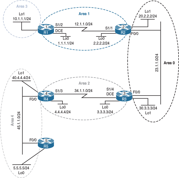
Figure 8-10 Virtual Links and GRE Tunnels
Figure 8-10 illustrates the topology that will used in the following tasks.
The same rules governing how all OSPF areas must be adjacent to Area 0 are maintained in OSPFv3. To maintain a logical capacity to support this, we have the same tools we used in OSPFv2. Virtual links are among the most efficient ways to maintain this adjacency to Area 0, even in OSPFv3. Remember that we are using the 32-bit address from a loopback interface or from a manually configured router ID, so this process will look exactly like it does on OSPFv2.
Task 1
Configure OSPF based on Table 8-3.
Table 8-3 Configure OSPF
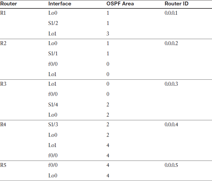
On R1:
R1(config)# router ospf 1
R1(config-router)# router-id 0.0.0.1
R1(config-router)# network 10.1.1.1 0.0.0.0 are 3
R1(config-router)# network 12.1.1.1 0.0.0.0 are 1
R1(config-router)# network 1.1.1.1 0.0.0.0 are 1
On R2:
R2(config)# router ospf 1
R2(config-router)# router-id 0.0.0.2
R2(config-router)# network 12.1.1.2 0.0.0.0 are 1
R2(config-router)# network 2.2.2.2 0.0.0.0 are 1
R2(config-router)# network 23.1.1.2 0.0.0.0 are 0
R2(config-router)# network 20.2.2.2 0.0.0.0 are 0
You should see the following console message:
%OSPF-5-ADJCHG: Process 1, Nbr 0.0.0.1 on Serial1/1 from LOADING to FULL,
Loading Done
On R3:
R3(config-if)# router ospf 1
R3(config-router)# router-id 0.0.0.3
R3(config-router)# network 23.1.1.3 0.0.0.0 are 0
R3(config-router)# network 3.3.3.3 0.0.0.0 are 2
R3(config-router)# network 34.1.1.3 0.0.0.0 are 2
R3(config-router)# network 30.3.3.3 0.0.0.0 are 0
You should see the following console message:
%OSPF-5-ADJCHG: Process 1, Nbr 0.0.0.2 on FastEthernet0/0 from LOADING to FULL,
Loading Done
On R4:
R4(config)# router ospf 1
R4(config-router)# router-id 0.0.0.4
R4(config-router)# network 34.1.1.4 0.0.0.0 area 2
R4(config-router)# network 4.4.4.4 0.0.0.0 are 2
R4(config-router)# network 45.1.1.4 0.0.0.0 are 4
R4(config-router)# network 40.4.4.4 0.0.0.0 are 4
You should also see this console message:
%OSPF-5-ADJCHG: Process 1, Nbr 0.0.0.3 on Serial1/3 from LOADING to FULL,
Loading Done
The following console message states that a virtual link is needed but it is not configured:
%OSPF-4-ERRRCV: Received invalid packet: mismatched area ID, from backbone area
must be virtual-link but not found from 23.1.1.3, FastEthernet0/0
On R5:
R5(config)# router ospf 1
R5(config-router)# router-id 0.0.0.5
R5(config-router)# network 45.1.1.5 0.0.0.0 are 4
R5(config-router)# network 5.5.5.5 0.0.0.0 are 4
Finally, you should see the following console message:
%OSPF-5-ADJCHG: Process 1, Nbr 0.0.0.4 on FastEthernet0/0 from LOADING to FULL,
Loading Done
Task 2
Ensure that the networks from Area 3 are reachable by R2, R3, and R4. Do not use a GRE tunnel to accomplish this task.
In OSPF, every non-zero area must be connected to Area 0 (the backbone area). This connection can be a physical or a logical connection. The area through which the virtual link is configured is called the transit area, and this area must have full routing information and can’t be a stub area of any kind.
When the virtual link is first configured, it is in the down state because R1 (0.0.0.1) and R2 (0.0.0.2) don’t have network layer reachability information (NLRI) to each other; therefore, all the LSAs need to be flooded and the SPF algorithm needs to be calculated so that these routers know how to reach each other through Area 1. Once the routers have NLRI for each other, they form an adjacency across the virtual link.
It is important to note that the OSPF packets between the endpoints of the virtual link are not multicast packets; they are tunneled packets from 12.1.1.1 (R1) to 12.1.1.2 (R2), or vice versa.
The virtual link configuration must be performed on the ABRs, and if one of the endpoints is not an ABR, the virtual link will not transition into the up state; to be a backbone (BB) router, there must be a minimum of one link in the BB area. Once the routers form an adjacency on the virtual link, R1 becomes a backbone router; once R1 becomes a BB router, because it has another connection to Area 3, it becomes an ABR.
Because Area 3 is not connected to Area 0, the routers in the other areas won’t be able to see the route(s) advertised by this area; therefore, a virtual link or a GRE tunnel must be configured to connect R1 (the router that connects Area 3 to Area 1) to R2 in Area 0.
Use the following steps to configure a virtual link:
Step 1. Because the virtual link is terminated on the ABRs using their router IDs, the router ID of these routers must be determined:
On R1:
R1# show ip ospf | include ID
Routing Process "ospf 1" with ID 0.0.0.1
On R2:
R2# show ip ospf | include ID
Routing Process "ospf 1" with ID 0.0.0.2
Step 2. Ensure that the router IDs are stable, meaning that they are statically configured on the routers—unless you are in the CCIE lab and are asked not to configure the router IDs. Even though in this case this can be bypassed (because the router IDs are 0.0.0.x, where x is the router number), it is still a good practice to go through so that you have a process.
On R1:
R1# show run | section router ospf
router ospf 1
router-id 0.0.0.1
network 1.1.1.1 0.0.0.0 area 1
network 10.1.1.1 0.0.0.0 area 3
network 12.1.1.1 0.0.0.0 area 1
On R2:
R2# show run | section router ospf
router ospf 1
router-id 0.0.0.2
network 2.2.2.2 0.0.0.0 area 1
network 12.1.1.2 0.0.0.0 area 1
network 20.2.2.2 0.0.0.0 area 0
network 23.1.1.2 0.0.0.0 area 0
Step 3. Ensure that the transit area is not a stub. Based on the preceding show command, you can see that the transit area, Area 1, is not a stub area.
Step 4. Configure the virtual links:
On R1:
R1(config)# router ospf 1
R1(config-router)# area 1 virtual-link 0.0.0.2
You should see the following console message every hello interval. These messages should stop once the virtual link is configured successfully:
On R2:
%OSPF-4-ERRRCV: Received invalid packet: mismatched area ID, from backbone area
must be virtual-link but not found from 12.1.1.1, Serial1/1
R2(config)# router ospf 1
R2(config-router)# area 1 virtual-link 0.0.0.1
You should see the following console message stating that an OSPF adjacency is established using the virtual link:
%OSPF-5-ADJCHG: Process 1, Nbr 0.0.0.1 on OSPF_VL0 from LOADING to FULL,
Loading Done
Step 5. The cost of the virtual link should not exceed 65534:
R2# show ip ospf virtual-links
Virtual Link OSPF_VL0 to router 0.0.0.1 is up
Run as demand circuit
DoNotAge LSA allowed.
Transit area 1, via interface Serial1/1
Topology-MTID Cost Disabled Shutdown Topology Name
0 781 no no Base
Transmit Delay is 1 sec, State POINT_TO_POINT,
Timer intervals configured, Hello 10, Dead 40, Wait 40, Retransmit 5
Hello due in 00:00:05
Adjacency State FULL (Hello suppressed)
Index 2/3, retransmission queue length 0, number of retransmission 0
First 0x0(0)/0x0(0) Next 0x0(0)/0x0(0)
Last retransmission scan length is 0, maximum is 0
Last retransmission scan time is 0 msec, maximum is 0 msec
You can see that the virtual link is up and its cost is 781. Because OSPF packets are tunneled packets from 12.1.1.1 (R1) to 12.1.1.2 (R2), the cost of the virtual link is based on the OSPF cost of all links from R1’s s1/2 interface to R2’s s1/1 interface. Let’s see the OSPF cost of the serial link between R1 and R2:
On R2:
R2# show ip ospf interface serial1/1 | include Cost
Process ID 1, router ID 0.0.0.2, network Type POINT_TO_POINT, Cost: 781
Topology-MTID Cost Disabled Shutdown Topology Name
Now let’s verify and test the configuration:
On R2:
R2# show ip route ospf | begin Gate
Gateway of last resort is not set
1.0.0.0/32 is subnetted, 1 subnets
O 1.1.1.1 [110/782] via 12.1.1.1, 00:46:58, Serial1/1
3.0.0.0/32 is subnetted, 1 subnets
O IA 3.3.3.3 [110/2] via 23.1.1.3, 00:45:18, FastEthernet0/0
4.0.0.0/32 is subnetted, 1 subnets
O IA 4.4.4.4 [110/783] via 23.1.1.3, 00:44:25, FastEthernet0/0
10.0.0.0/32 is subnetted, 1 subnets
O IA 10.1.1.1 [110/782] via 12.1.1.1, 00:00:18, Serial1/1
30.0.0.0/32 is subnetted, 1 subnets
O 30.3.3.3 [110/2] via 23.1.1.3, 00:45:18, FastEthernet0/0
34.0.0.0/24 is subnetted, 1 subnets
O IA 34.1.1.0 [110/782] via 23.1.1.3, 00:45:18, FastEthernet0/0
R2# ping 10.1.1.1
Type escape sequence to abort.
Sending 5, 100-byte ICMP Echos to 10.1.1.1, timeout is 2 seconds:
!!!!!
Success rate is 100 percent (5/5), round-trip min/avg/max = 48/50/52 ms
On R3:
R3# show ip route ospf | begin Gate
Gateway of last resort is not set
1.0.0.0/32 is subnetted, 1 subnets
O IA 1.1.1.1 [110/783] via 23.1.1.2, 00:54:56, FastEthernet0/0
2.0.0.0/32 is subnetted, 1 subnets
O IA 2.2.2.2 [110/2] via 23.1.1.2, 00:54:56, FastEthernet0/0
4.0.0.0/32 is subnetted, 1 subnets
O 4.4.4.4 [110/782] via 34.1.1.4, 00:54:01, Serial1/4
10.0.0.0/32 is subnetted, 1 subnets
O IA 10.1.1.1 [110/783] via 23.1.1.2, 00:09:53, FastEthernet0/0
12.0.0.0/24 is subnetted, 1 subnets
O IA 12.1.1.0 [110/782] via 23.1.1.2, 00:54:56, FastEthernet0/0
20.0.0.0/32 is subnetted, 1 subnets
O 20.2.2.2 [110/2] via 23.1.1.2, 00:54:56, FastEthernet0/0
R3# ping 10.1.1.1
Type escape sequence to abort.
Sending 5, 100-byte ICMP Echos to 10.1.1.1, timeout is 2 seconds:
!!!!!
Success rate is 100 percent (5/5), round-trip min/avg/max = 48/50/52 ms
Task 3
Ensure that the routers in Area 4 can see and have NLRI for all routes advertised in this routing domain. You should use loopback0 IP addresses. Do not change the area in which they are already configured. Also, do not use a virtual link to accomplish this task.
Let’s check the routing table of R5:
On R5:
R5# show ip route ospf | begin Gate
Gateway of last resort is not set
40.0.0.0/32 is subnetted, 1 subnets
O 40.4.4.4 [110/2] via 45.1.1.4, 01:00:16, FastEthernet0/0
The reason R5 only sees network 40.4.4.0/24 is because Area 4 does not have a connection (logical or physical) to Area 0. In order to rectify this problem, you must configure a virtual link. Because configuring virtual links is prohibited by the condition of this task, a GRE tunnel is configured instead. The task also states that you must use loopback0 IP addresses.
On R4:
R4(config)# interface tunnel 43
R4(config-if)# ip unnumbered loopback 0
R4(config-if)# tunnel source 34.1.1.4
R4(config-if)# tunnel destination 34.1.1.3
On R3:
R3(config)# interface tunnel 34
R3(config-if)# ip unnumbered loopback 0
R3(config-if)# tunnel source 34.1.1.3
R3(config-if)# tunnel destination 34.1.1.4
You should see the following console message:
%LINEPROTO-5-UPDOWN: Line protocol on Interface Tunnel34, changed state to up
When configuring a GRE tunnel, you must configure the IP address of the tunnel in Area 0. This can become a major problem when “IP unnumbered loopback” interface configuration commands are used, especially when the loopback interfaces are configured in different areas.
Let’s verify the configuration:
On R5:
R5# show ip route ospf | begin Gate
Gateway of last resort is not set
40.0.0.0/32 is subnetted, 1 subnets
O 40.4.4.4 [110/2] via 45.1.1.4, 01:07:31, FastEthernet0/0
R5 cannot see any routes from the other areas. Why?
The tunnel interface must be configured in Area 0. Let’s verify this:
R4# show ip ospf interface brief
Interface PID Area IP Address/Mask Cost State Nbrs F/C
Lo0 1 2 4.4.4.4/24 1 LOOP 0/0
Tu43 1 2 Unnumbered Lo0 1000 P2P 1/1
Se1/3 1 2 34.1.1.4/24 781 P2P 1/1
Lo1 1 4 40.4.4.4/24 1 LOOP 0/0
Fa0/0 1 4 45.1.1.4/24 1 DR 1/1
You can see the problem: The tunnel interface is configured based on the loopback0 interface, which is running in Area 2. Because the task states that you cannot change the area assignment of any interface, you’ll need to go to the tunnel interface and configure OSPF directly under the tunnel interface:
On R4:
R4(config)# interface tunnel 43
R4(config-if)# ip ospf 1 area 0
On R3:
R3(config)# interface tunnel 34
R3(config-if)# ip ospf 1 area 0
You should see the following console message:
%OSPF-5-ADJCHG: Process 1, Nbr 0.0.0.4 on Tunnel34 from LOADING to FULL,
Loading Done
Let’s verify and test the configuration:
On R5:
R5# show ip route ospf | begin Gate
Gateway of last resort is not set
1.0.0.0/32 is subnetted, 1 subnets
O IA 1.1.1.1 [110/1784] via 45.1.1.4, 00:00:50, FastEthernet0/0
2.0.0.0/32 is subnetted, 1 subnets
O IA 2.2.2.2 [110/1003] via 45.1.1.4, 00:00:50, FastEthernet0/0
3.0.0.0/32 is subnetted, 1 subnets
O IA 3.3.3.3 [110/783] via 45.1.1.4, 00:01:15, FastEthernet0/0
4.0.0.0/32 is subnetted, 1 subnets
O IA 4.4.4.4 [110/2] via 45.1.1.4, 00:01:15, FastEthernet0/0
10.0.0.0/32 is subnetted, 1 subnets
O IA 10.1.1.1 [110/1784] via 45.1.1.4, 00:00:50, FastEthernet0/0
12.0.0.0/24 is subnetted, 1 subnets
O IA 12.1.1.0 [110/1783] via 45.1.1.4, 00:00:50, FastEthernet0/0
20.0.0.0/32 is subnetted, 1 subnets
O IA 20.2.2.2 [110/1003] via 45.1.1.4, 00:00:50, FastEthernet0/0
23.0.0.0/24 is subnetted, 1 subnets
O IA 23.1.1.0 [110/1002] via 45.1.1.4, 00:00:50, FastEthernet0/0
30.0.0.0/32 is subnetted, 1 subnets
O IA 30.3.3.3 [110/1002] via 45.1.1.4, 00:00:50, FastEthernet0/0
34.0.0.0/24 is subnetted, 1 subnets
O IA 34.1.1.0 [110/782] via 45.1.1.4, 00:01:15, FastEthernet0/0
40.0.0.0/32 is subnetted, 1 subnets
O 40.4.4.4 [110/2] via 45.1.1.4, 01:13:26, FastEthernet0/0
R5# ping 10.1.1.1
Type escape sequence to abort.
Sending 5, 100-byte ICMP Echos to 10.1.1.1, timeout is 2 seconds:
!!!!!
Success rate is 100 percent (5/5), round-trip min/avg/max = 64/64/64 ms
R4# show ip ospf interface brief
Interface PID Area IP Address/Mask Cost State Nbrs F/C
Tu43 1 0 Unnumbered Lo0 1000 P2P 1/1
Lo0 1 2 4.4.4.4/24 1 LOOP 0/0
Se1/3 1 2 34.1.1.4/24 781 P2P 1/1
Lo1 1 4 40.4.4.4/24 1 LOOP 0/0
Fa0/0 1 4 45.1.1.4/24 1 DR 1/1
Unlike virtual links, whose cost is based on the OSPF cost of all links between the ABRs, the cost of the GRE tunnel is not based on the cost of all links between the endpoints of the tunnel. Let’s verify:
On R4:
R4# show ip ospf interface tunnel 43 | Include Cost
Process ID 1, router ID 0.0.0.4, network Type POINT_TO_POINT, Cost: 1000
Topology-MTID Cost Disabled Shutdown Topology Name
Erase the startup config and reload the routers before proceeding to the next lab.
Lab 8-10: OSPF Stub, Totally Stubby, and NSSA Areas
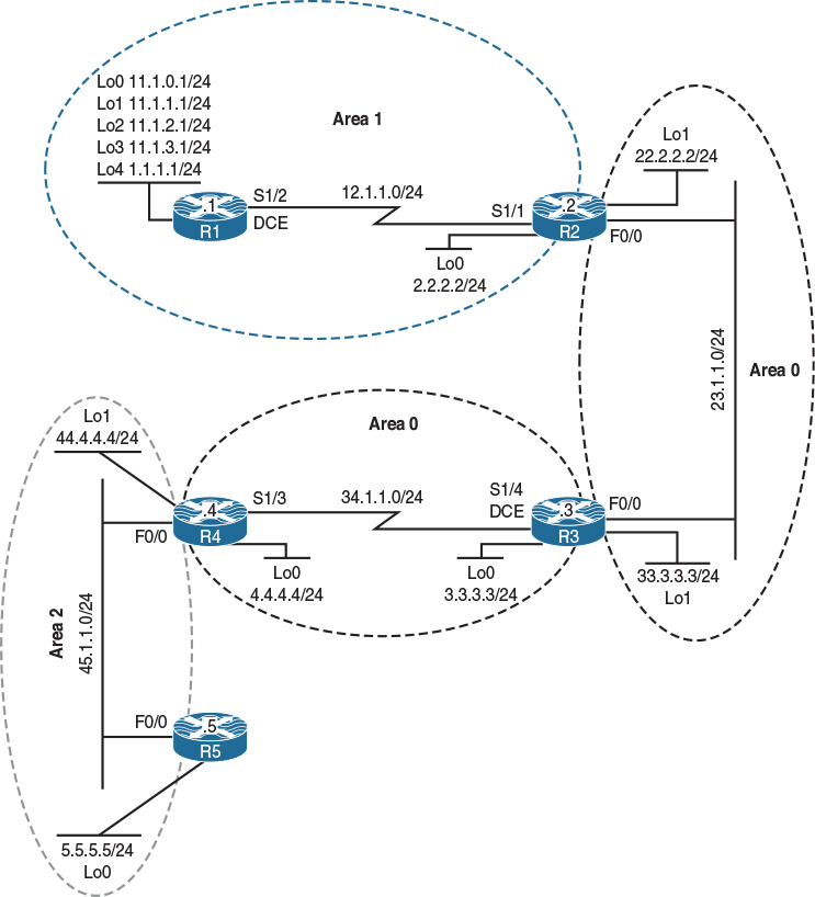
Figure 8-11 OSPF Stub, Totally Stubby, and NSSA Areas
Figure 8-11 illustrates the topology that will used in the following tasks.
The router IDSs in this lab should be configured as follows:
R1: 0.0.0.1
R2: 0.0.0.2
R3: 0.0.0.3
R4: 0.0.0.4
R5: 0.0.0.5
Task 1
Configure OSPF Area 1 on all directly connected interfaces of R1. The loopback interfaces should be advertised with their correct mask.
Let’s see R1’s directly connected interfaces:
On R1:
R1# show ip interface brief | exclude unassigned
Interface IP-Address OK? Method Status Protocol
Serial1/2 12.1.1.1 YES manual up up
Loopback0 11.1.0.1 YES manual up up
Loopback1 11.1.1.1 YES manual up up
Loopback2 11.1.2.1 YES manual up up
Loopback3 11.1.3.1 YES manual up up
Loopback4 1.1.1.1 YES manual up up
R1(config)# interface range lo0 - 4
R1(config-if-range)# ip ospf network point-to-point
R1(config)# router ospf 1
R1(config-router)# router-id 0.0.0.1
R1(config-router)# network 11.1.0.1 0.0.0.0 area 1
R1(config-router)# network 11.1.1.1 0.0.0.0 area 1
R1(config-router)# network 11.1.2.1 0.0.0.0 area 1
R1(config-router)# network 11.1.3.1 0.0.0.0 area 1
R1(config-router)# network 1.1.1.1 0.0.0.0 area 1
R1(config-router)# network 12.1.1.1 0.0.0.0 area 1
Task 2
Configure R2’s s1/1 and loopback0 interfaces in OSPF Area 1 and then configure R2’s f0/0 and loopback1 interfaces in Area 0. The loopback interfaces should be advertised with their correct mask.
Let’s see R2’s directly connected interfaces:
On R2:
R2# show ip interface brief | exclude unassigned
Interface IP-Address OK? Method Status Protocol
FastEthernet0/0 23.1.1.2 YES manual up up
Serial1/1 12.1.1.2 YES manual up up
Loopback0 2.2.2.2 YES manual up up
Loopback1 22.2.2.2 YES manual up up
R2(config)# interface range lo 0 - 1
R2(config-if-range)# ip ospf network point-to-point
R2(config)# router ospf 1
R2(config-router)# router-id 0.0.0.2
R2(config-router)# network 12.1.1.2 0.0.0.0 area 1
R2(config-router)# network 2.2.2.2 0.0.0.0 area 1
R2(config-router)# network 22.2.2.2 0.0.0.0 area 0
R2(config-router)# network 23.1.1.2 0.0.0.0 area 0
You should see the following console message:
%OSPF-5-ADJCHG: Process 1, Nbr 0.0.0.1 on Serial1/1 from LOADING to FULL,
Loading Done
Let’s verify the configuration:
R2# show ip route ospf | begin Gate
Gateway of last resort is not set
1.0.0.0/24 is subnetted, 1 subnets
O 1.1.1.0 [110/782] via 12.1.1.1, 00:06:32, Serial1/1
11.0.0.0/24 is subnetted, 4 subnets
O 11.1.0.0 [110/782] via 12.1.1.1, 00:06:32, Serial1/1
O 11.1.1.0 [110/782] via 12.1.1.1, 00:06:32, Serial1/1
O 11.1.2.0 [110/782] via 12.1.1.1, 00:06:32, Serial1/1
O 11.1.3.0 [110/782] via 12.1.1.1, 00:06:32, Serial1/1
Task 3
Configure all of R3’s directly connected interfaces in Area 0.
Let’s see R3’s directly connected interfaces:
On R3:
R3# show ip interface brief | exclude unassigned
Interface IP-Address OK? Method Status Protocol
FastEthernet0/0 23.1.1.3 YES manual up up
Serial1/4 34.1.1.3 YES manual up up
Loopback0 3.3.3.3 YES manual up up
Loopback1 33.3.3.3 YES manual up up
R3(config)# interface range loopback 0 - 1
R3(config-if-range)# ip ospf network point-to-point
R3(config)# router ospf 1
R3(config-router)# router-id 0.0.0.3
R3(config-router)# network 3.3.3.3 0.0.0.0 area 0
R3(config-router)# network 33.3.3.3 0.0.0.0 area 0
R3(config-router)# network 23.1.1.3 0.0.0.0 area 0
R3(config-router)# network 34.1.1.3 0.0.0.0 area 0
You should see the following console message:
%OSPF-5-ADJCHG: Process 1, Nbr 0.0.0.2 on FastEthernet0/0 from LOADING to FULL, Loading Done
Let’s verify the configuration:
R3# show ip route ospf | begin Gate
Gateway of last resort is not set
1.0.0.0/24 is subnetted, 1 subnets
O IA 1.1.1.0 [110/783] via 23.1.1.2, 00:04:23, FastEthernet0/0
2.0.0.0/24 is subnetted, 1 subnets
O IA 2.2.2.0 [110/2] via 23.1.1.2, 00:04:23, FastEthernet0/0
11.0.0.0/24 is subnetted, 4 subnets
O IA 11.1.0.0 [110/783] via 23.1.1.2, 00:04:23, FastEthernet0/0
O IA 11.1.1.0 [110/783] via 23.1.1.2, 00:04:23, FastEthernet0/0
O IA 11.1.2.0 [110/783] via 23.1.1.2, 00:04:23, FastEthernet0/0
O IA 11.1.3.0 [110/783] via 23.1.1.2, 00:04:23, FastEthernet0/0
12.0.0.0/24 is subnetted, 1 subnets
O IA 12.1.1.0 [110/782] via 23.1.1.2, 00:02:11, FastEthernet0/0
22.0.0.0/24 is subnetted, 1 subnets
O 22.2.2.0 [110/2] via 23.1.1.2, 00:04:23, FastEthernet0/0
Task 4
Configure OSPF Area 2 based on Table 8-4.
Table 8-4 Configuration of OSPF Area 2
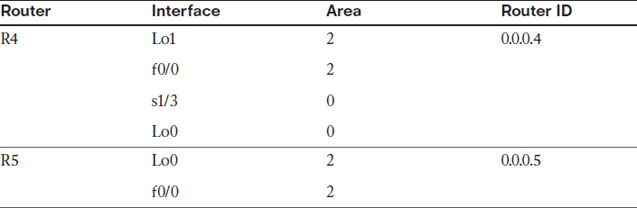
Let’s see R4’s directly connected interfaces:
On R4:
R4# show ip interface brief | exclude unassigned
Interface IP-Address OK? Method Status Protocol
FastEthernet0/0 45.1.1.4 YES manual up up
Serial1/3 34.1.1.4 YES manual up up
Loopback0 4.4.4.4 YES manual up up
Loopback1 44.4.4.4 YES manual up up
R4(config)# interface range loopback 0 - 1
R4(config-if-range)# ip ospf network point-to-point
R4(config)# router ospf 1
R4(config-router)# router-id 0.0.0.4
R4(config-router)# network 44.4.4.4 0.0.0.0 area 2
R4(config-router)# network 45.1.1.4 0.0.0.0 area 2
R4(config-router)# network 34.1.1.4 0.0.0.0 area 0
R4(config-router)# network 4.4.4.4 0.0.0.0 area 0
You should see the following console message:
%OSPF-5-ADJCHG: Process 1, Nbr 0.0.0.3 on Serial1/3 from LOADING to FULL,
Loading Done
On R5:
R5# show ip interface brief | exclude unassigned
Interface IP-Address OK? Method Status Protocol
FastEthernet0/0 45.1.1.5 YES manual up up
Loopback0 5.5.5.5 YES manual up up
R5(config)# interface loopback 0
R5(config-if)# ip ospf network point-to-point
R5(config)# router ospf 1
R5(config-router)# router-id 0.0.0.5
R5(config-router)# network 5.5.5.5 0.0.0.0 area 2
R5(config-router)# network 45.1.1.5 0.0.0.0 area 2
You should see the following console message:
%OSPF-5-ADJCHG: Process 1, Nbr 0.0.0.4 on FastEthernet0/0 from LOADING to FULL,
Loading Done
Let’s verify the configuration:
On R5:
R5# show ip route ospf | begin Gate
Gateway of last resort is not set
1.0.0.0/24 is subnetted, 1 subnets
O IA 1.1.1.0 [110/1565] via 45.1.1.4, 00:00:46, FastEthernet0/0
2.0.0.0/24 is subnetted, 1 subnets
O IA 2.2.2.0 [110/784] via 45.1.1.4, 00:00:46, FastEthernet0/0
3.0.0.0/24 is subnetted, 1 subnets
O IA 3.3.3.0 [110/783] via 45.1.1.4, 00:00:46, FastEthernet0/0
4.0.0.0/24 is subnetted, 1 subnets
O IA 4.4.4.0 [110/2] via 45.1.1.4, 00:00:46, FastEthernet0/0
11.0.0.0/24 is subnetted, 4 subnets
O IA 11.1.0.0 [110/1565] via 45.1.1.4, 00:00:46, FastEthernet0/0
O IA 11.1.1.0 [110/1565] via 45.1.1.4, 00:00:46, FastEthernet0/0
O IA 11.1.2.0 [110/1565] via 45.1.1.4, 00:00:46, FastEthernet0/0
O IA 11.1.3.0 [110/1565] via 45.1.1.4, 00:00:46, FastEthernet0/0
12.0.0.0/24 is subnetted, 1 subnets
O IA 12.1.1.0 [110/1564] via 45.1.1.4, 00:00:46, FastEthernet0/0
22.0.0.0/24 is subnetted, 1 subnets
O IA 22.2.2.0 [110/784] via 45.1.1.4, 00:00:46, FastEthernet0/0
23.0.0.0/24 is subnetted, 1 subnets
O IA 23.1.1.0 [110/783] via 45.1.1.4, 00:00:46, FastEthernet0/0
33.0.0.0/24 is subnetted, 1 subnets
O IA 33.3.3.0 [110/783] via 45.1.1.4, 00:00:46, FastEthernet0/0
34.0.0.0/24 is subnetted, 1 subnets
O IA 34.1.1.0 [110/782] via 45.1.1.4, 00:00:46, FastEthernet0/0
44.0.0.0/24 is subnetted, 1 subnets
O 44.4.4.0 [110/2] via 45.1.1.4, 00:00:46, FastEthernet0/0
Task 5
Configure and redistribute the loopback30 interface as 130.1.1.3/32 on R3:
On R3:
R3(config)# interface loopback 30
R3(config-if)# ip address 130.1.1.3 255.255.255.255
R3(config)# route-map tst permit 10
R3(config-route-map)# match interface loopback 30
R3(config)# router ospf 1
R3(config-router)# redistribute connected route-map tst subnets
Let’s verify the configuration:
On R1:
R1# show ip route ospf | include 130
130.1.0.0/32 is subnetted, 1 subnets
O E2 130.1.1.3 [110/20] via 12.1.1.2, 00:00:55, Serial1/2
Task 6
Configure Area 1 such that it does not receive Type-4 or Type-5 LSAs, but the routers in this area should still maintain the inter-area routes in their routing table. These routers should have reachability to the existing and future external routes redistributed into this routing domain.
We can configure the OSPF stub area to accomplish this task. Here are some important points to understand about a stub area:
![]() A stub area cannot be a transit area for virtual links. GRE tunnels should be used instead.
A stub area cannot be a transit area for virtual links. GRE tunnels should be used instead.
![]() A stub area cannot have an ASBR.
A stub area cannot have an ASBR.
![]() The backbone area cannot be configured as a stub area.
The backbone area cannot be configured as a stub area.
![]() Every router and the ABR(s) of that area should be configured with the area xx stub command to match the area stub flag; otherwise, the adjacency will be torn down.
Every router and the ABR(s) of that area should be configured with the area xx stub command to match the area stub flag; otherwise, the adjacency will be torn down.
![]() External routes are not allowed in a stub area, but the routers in the stub area can connect to the external routes via the default route that is injected by their ABR.
External routes are not allowed in a stub area, but the routers in the stub area can connect to the external routes via the default route that is injected by their ABR.
![]() A stub area cannot have Type-4 or Type-5 LSAs.
A stub area cannot have Type-4 or Type-5 LSAs.
![]() By default, the cost of the default route injected into this area by the ABR is 1; this can be verified using the show ip ospf and/or show ip route commands. The cost of the default route can be changed using area xx default-cost cc, where xx is the area number and cc is the desired cost.
By default, the cost of the default route injected into this area by the ABR is 1; this can be verified using the show ip ospf and/or show ip route commands. The cost of the default route can be changed using area xx default-cost cc, where xx is the area number and cc is the desired cost.
On R1:
R1(config)# router ospf 1
R1(config-router)# area 1 stub
You should see the following console message:
%OSPF-5-ADJCHG: Process 1, Nbr 0.0.0.2 on Serial1/2 from FULL to DOWN,
neighbor Down: Adjacency forced to reset
Note The adjacency with R2 (0.0.0.2) transitioned from Full to Down because the area stub flag no longer matches:
On R2:
R2(config)# router ospf 1
R2(config-router)# area 1 stub
You should see the following console message stating that the adjacency is in the FULL state:
%OSPF-5-ADJCHG: Process 1, Nbr 0.0.0.1 on Serial1/1 from LOADING to FULL,
Loading Done
Let’s verify the configuration:
On R1:
R1# show ip ospf | include area
Supports area transit capability
Number of areas in this router is 1. 0 normal 1 stub 0 nssa
Number of areas transit capable is 0
Number of interfaces in this area is 6
It is a stub area
R1# show ip route ospf | include 0.0.0.0/0
O*IA 0.0.0.0/0 [110/782] via 12.1.1.2, 00:01:40, Serial1/2
The output of the preceding show command reveals that the cost of the default route from R1’s perspective is 782. Why 782? The default cost of the default route is 1 plus the cost of the serial link, which is 781.
Let’s verify this:
On R2:
R2# show ip ospf | include cost
generates stub default route with cost 1
R2# show ip ospf interface serial 1/1 | include Cost
Process ID 1, router ID 0.0.0.1, network Type POINT_TO_POINT, Cost: 781
Topology-MTID Cost Disabled Shutdown Topology Name
Therefore, if 1 is added to 781, you should see a resulting cost of 782.
The following command is a hidden command. Therefore, pressing the Tab key will not complete it.
On R1:
R1# show ip ospf route | include 0.0.0.0
*> 0.0.0.0/0, Inter, cost 782, area 1
Based on the following successful ping, you can see that the routers in Area 1 have reachability to the external routes that are redistributed in other areas of this routing domain:
R1# ping 130.1.1.3
Type escape sequence to abort.
Sending 5, 100-byte ICMP Echos to 130.1.1.3, timeout is 2 seconds:
!!!!!
Success rate is 100 percent (5/5), round-trip min/avg/max = 28/29/32 ms
Task 7
Area 2 should not receive Type-3, -4, or -5 LSAs. These routers should have reachability to the existing and future inter-area and external routes redistributed into this routing domain.
You can reduce the size of the routing table further by configuring an area as “totally stubby.” Because all the “IA” and “E” (inter-area and external) routes can be reached via a default route, which is injected by the ABR of this area, there is no reason to maintain these routes.
On R5:
R5(config)# router ospf 1
R5(config-router)# area 2 stub
You should see the following console message stating that the adjacency transitioned from the FULL state to the DOWN state. This happened because the area stub flag no longer matches (remember that if the area stub flag does not match, the adjacency cannot be established). Therefore, the preceding command must be configured on all the routers within Area 2.
%OSPF-5-ADJCHG: Process 1, Nbr 0.0.0.4 on FastEthernet0/0 from FULL to DOWN,
neighbor Down: Adjacency forced to reset
On R4:
R4(config)# router ospf 1
R4(config-router)# area 2 stub no-summary
The preceding command must only be configured on the ABR of this area.
Let’s verify the configuration:
On R5:
R5# show ip route ospf | begin Gate
Gateway of last resort is 45.1.1.4 to network 0.0.0.0
O*IA 0.0.0.0/0 [110/2] via 45.1.1.4, 00:00:14, FastEthernet0/0
44.0.0.0/24 is subnetted, 1 subnets
O 44.4.4.0 [110/2] via 45.1.1.4, 00:00:14, FastEthernet0/0
Here are some important points to understand about a “totally stubby” area:
![]() A totally stub area cannot be a transit area for virtual links. GRE tunnels should be used instead.
A totally stub area cannot be a transit area for virtual links. GRE tunnels should be used instead.
![]() A totally stub area cannot have an ASBR.
A totally stub area cannot have an ASBR.
![]() The backbone area cannot be configured as a totally stub area.
The backbone area cannot be configured as a totally stub area.
![]() The routers within the area should be configured with the area xx stub command, whereas the ABR of the totally stub area must be configured with area xx stub no-summary.
The routers within the area should be configured with the area xx stub command, whereas the ABR of the totally stub area must be configured with area xx stub no-summary.
![]() External routes are not allowed in a totally stub area, but the routers in the totally stub area can connect to the external routes via the default route that is injected into the area by their ABR.
External routes are not allowed in a totally stub area, but the routers in the totally stub area can connect to the external routes via the default route that is injected into the area by their ABR.
![]() By default, the cost of the default route injected into this area by the ABR is 1. This can be verified using the show ip ospf command on the ABR and/or the show ip route command on the other routers in the area. The cost of the default route can be changed using area xx default-cost cc, where xx is the area number and cc is the desired cost.
By default, the cost of the default route injected into this area by the ABR is 1. This can be verified using the show ip ospf command on the ABR and/or the show ip route command on the other routers in the area. The cost of the default route can be changed using area xx default-cost cc, where xx is the area number and cc is the desired cost.
![]() The routers in a totally stub area don’t get inter-area routes, but they have NLRI for the inter-area routes via the default route that is injected by the ABR.
The routers in a totally stub area don’t get inter-area routes, but they have NLRI for the inter-area routes via the default route that is injected by the ABR.
Let’s see why the default route is the only inter-area route injected into this area:
R4# show ip ospf database summary 0.0.0.0
OSPF router with ID (0.0.0.4) (Process ID 1)
Summary Net Link States (Area 2)
LS age: 331
Options: (No TOS-capability, DC, Upward)
LS Type: Summary Links(Network)
Link State ID: 0.0.0.0 (summary network Number)
Advertising Router: 0.0.0.4
LS Seq Number: 80000001
Checksum: 0x99A0
Length: 28
network Mask: /0
MTID: 0 Metric: 1
You can see that the default route is injected by the ABR—in this case, R4 (0.0.0.4)—and it was generated within Area 2. Therefore, it is wrong to say that the default route is the only inter-area route injected into the totally stubby area.
The inter-area routes that have originated in the other areas are the only routes that are blocked. Because the default route is originated in Area 2, it is not blocked.
Task 8
Redistribute Lo0–4 interfaces of R1 into this routing domain. Reconfigure Area 1 such that it only receives and propagates LSA Types 1, 2, 3, and 7. This area should not have the ability to connect to any external routes redistributed elsewhere within this routing domain.
Because a stub area cannot have external routes, Area 1 must be converted into an NSSA, meaning that Area 1 wants to be a stub area but at the same time allow the existence of external routes.
Let’s remove the following commands from R1:
On R1:
R1(config)# router ospf 1
R1(config-router)# no network 1.1.1.1 0.0.0.0 area 1
R1(config-router)# no network 11.1.0.1 0.0.0.0 area 1
R1(config-router)# no network 11.1.1.1 0.0.0.0 area 1
R1(config-router)# no network 11.1.2.1 0.0.0.0 area 1
R1(config-router)# no network 11.1.3.1 0.0.0.0 area 1
R1(config-router)# no area 1 stub
R1(config-router)# area 1 nssa
You should see the following console message:
%OSPF-5-ADJCHG: Process 1, Nbr 0.0.0.2 on Serial1/2 from DOWN to DOWN,
neighbor Down: Adjacency forced to reset
R1(config)# route-map TST permit 10
R1(config-route-map)# match interface lo0 lo1 lo2 lo3 lo4
R1(config)# router ospf 1
R1(config-router)# redistribute connected route-map TST subnets
On R2:
R2(config)# router ospf 1
R2(config-router)# no area 1 stub
R2(config-router)# area 1 nssa
You should see this console message as well:
%OSPF-5-ADJCHG: Process 1, Nbr 0.0.0.1 on Serial1/1 from LOADING to FULL,
Loading Done
Let’s verify the configuration:
Note R1 does not have a default route because the ABR (R2) did not inject one.
On R2:
R1# show ip route ospf | include 0.0.0.0/0
On R2:
R2# show ip route ospf | begin Gate
Gateway of last resort is not set
1.0.0.0/24 is subnetted, 1 subnets
O N2 1.1.1.0 [110/20] via 12.1.1.1, 00:02:43, Serial1/1
3.0.0.0/24 is subnetted, 1 subnets
O 3.3.3.0 [110/2] via 23.1.1.3, 00:02:53, FastEthernet0/0
4.0.0.0/24 is subnetted, 1 subnets
O 4.4.4.0 [110/783] via 23.1.1.3, 00:02:53, FastEthernet0/0
5.0.0.0/24 is subnetted, 1 subnets
O IA 5.5.5.0 [110/784] via 23.1.1.3, 00:02:53, FastEthernet0/0
11.0.0.0/24 is subnetted, 4 subnets
O N2 11.1.0.0 [110/20] via 12.1.1.1, 00:02:43, Serial1/1
O N2 11.1.1.0 [110/20] via 12.1.1.1, 00:02:43, Serial1/1
O N2 11.1.2.0 [110/20] via 12.1.1.1, 00:02:43, Serial1/1
O N2 11.1.3.0 [110/20] via 12.1.1.1, 00:02:43, Serial1/1
33.0.0.0/24 is subnetted, 1 subnets
O 33.3.3.0 [110/2] via 23.1.1.3, 00:02:53, FastEthernet0/0
34.0.0.0/24 is subnetted, 1 subnets
O 34.1.1.0 [110/782] via 23.1.1.3, 00:02:53, FastEthernet0/0
44.0.0.0/24 is subnetted, 1 subnets
O IA 44.4.4.0 [110/783] via 23.1.1.3, 00:02:53, FastEthernet0/0
45.0.0.0/24 is subnetted, 1 subnets
O IA 45.1.1.0 [110/783] via 23.1.1.3, 00:02:53, FastEthernet0/0
130.1.0.0/32 is subnetted, 1 subnets
O E2 130.1.1.3 [110/20] via 23.1.1.3, 00:02:53, FastEthernet0/0
Note R2 received the external routes from Area 1 as “N2” and converts them all to “E2.”
On R4:
R4# show ip route ospf | begin Gate
Gateway of last resort is not set
1.0.0.0/24 is subnetted, 1 subnets
O E2 1.1.1.0 [110/20] via 34.1.1.3, 00:03:29, Serial1/3
2.0.0.0/24 is subnetted, 1 subnets
O IA 2.2.2.0 [110/783] via 34.1.1.3, 00:22:15, Serial1/3
3.0.0.0/24 is subnetted, 1 subnets
O 3.3.3.0 [110/782] via 34.1.1.3, 00:22:15, Serial1/3
5.0.0.0/24 is subnetted, 1 subnets
O 5.5.5.0 [110/2] via 45.1.1.5, 00:22:03, FastEthernet0/0
11.0.0.0/24 is subnetted, 4 subnets
O E2 11.1.0.0 [110/20] via 34.1.1.3, 00:03:29, Serial1/3
O E2 11.1.1.0 [110/20] via 34.1.1.3, 00:03:29, Serial1/3
O E2 11.1.2.0 [110/20] via 34.1.1.3, 00:03:29, Serial1/3
O E2 11.1.3.0 [110/20] via 34.1.1.3, 00:03:29, Serial1/3
12.0.0.0/24 is subnetted, 1 subnets
O IA 12.1.1.0 [110/1563] via 34.1.1.3, 00:22:15, Serial1/3
22.0.0.0/24 is subnetted, 1 subnets
O 22.2.2.0 [110/783] via 34.1.1.3, 00:22:15, Serial1/3
23.0.0.0/24 is subnetted, 1 subnets
O 23.1.1.0 [110/782] via 34.1.1.3, 00:22:15, Serial1/3
33.0.0.0/24 is subnetted, 1 subnets
O 33.3.3.0 [110/782] via 34.1.1.3, 00:22:15, Serial1/3
130.1.0.0/32 is subnetted, 1 subnets
O E2 130.1.1.3 [110/20] via 34.1.1.3, 00:15:19, Serial1/3
In an NSSA area, the ABR receives the Type-7 LSAs and converts them into Type-5 LSAs. The following can confirm this fact:
R2# show ip ospf database nssa-external | include Link State
Type-7 AS External Link States (Area 1)
Link State ID: 1.1.1.0 (External network Number )
Link State ID: 11.1.0.0 (External network Number )
Link State ID: 11.1.1.0 (External network Number )
Link State ID: 11.1.2.0 (External network Number )
Link State ID: 11.1.3.0 (External network Number )
R2# show ip ospf database external | include Link State
Type-5 AS External Link States
Link State ID: 1.1.1.0 (External network Number )
Link State ID: 11.1.0.0 (External network Number )
Link State ID: 11.1.1.0 (External network Number )
Link State ID: 11.1.2.0 (External network Number )
Link State ID: 11.1.3.0 (External network Number )
Link State ID: 130.1.1.3 (External Network Number )
This happens because the ASBR in an NSSA area sets the “P” bit when it redistributes external routes. This bit instructs the ABR(s) to translate the Type-7 LSAs to Type-5 LSAs. You can see the P bit in the output of the following show command on R1:
On R1:
R1# show ip ospf database nssa-external
OSPF Router with ID (0.0.0.1) (Process ID 1)
Type-7 AS External Link States (Area 1)
LS age: 566
Options: (No TOS-capability, Type 7/5 translation, DC)
LS Type: AS External Link
Link State ID: 1.1.1.0 (External Network Number )
Advertising Router: 0.0.0.1
LS Seq Number: 80000001
Checksum: 0xD4AE
Length: 36
Network Mask: /24
Metric Type: 2 (Larger than any link state path)
MTID: 0
Metric: 20
Forward Address: 12.1.1.1
External Route Tag: 0
(The rest of the output is omitted for brevity)
Task 9
Configure the following loopback interfaces on R5:
Lo1: 55.5.1.5/24
Lo2: 55.5.2.5/24
Lo3: 55.5.3.5/24
Lo4: 55.5.4.5/24
On R5:
R5(config-if)# interface loopback 1
R5(config-if)# ip address 55.5.1.5 255.255.255.0
R5(config-if)# interface loopback 2
R5(config-if)# ip address 55.5.2.5 255.255.255.0
R5(config-if)# interface loopback 3
R5(config-if)# ip address 55.5.3.5 255.255.255.0
R5(config-if)# interface loopback 4
R5(config-if)# ip address 55.5.4.5 255.255.255.0
Let’s verify the configuration:
On R5:
R5# show ip interface brief | exclude unassociated
Interface IP-Address OK? Method Status Protocol
FastEthernet0/0 45.1.1.5 YES manual up up
Loopback0 5.5.5.5 YES manual up up
Loopback1 55.5.1.5 YES manual up up
Loopback2 55.5.2.5 YES manual up up
Loopback3 55.5.3.5 YES manual up up
Loopback4 55.5.4.5 YES manual up up
Task 10
Redistribute the Lo1–4 interfaces on R5. Configure the appropriate router(s) such that the routers in this area only maintain and propagate LSA Types 1, 2, 3, and 7 and a default route.
Because Area 2 is a totally stubby area, it can’t have external routes unless it’s converted into an NSSA because the task states that the routers of this area should also get a default route. The ABR of this area (R4) is configured to inject a default route using the default-information-originate keyword.
On R5:
R5(config-if)# route-map TST permit 10
R5(config-route-map)# match interface lo1 lo2 lo3 lo4
R5(config)# router ospf 1
R5(config-router)# no area 2 stub
R5(config-router)# area 2 nssa
R5(config-router)# redistribute connected subnets route-map TST
On R4:
R4(config)# router ospf 1
R4(config-router)# no area 2 stub
R4(config-router)# area 2 nssa default-information-originate
You should see the following console message:
%OSPF-5-ADJCHG: Process 1, Nbr 0.0.0.5 on FastEthernet0/0 from LOADING to FULL,
Loading Done
The default-information-originate keyword at the end of the area 2 nssa command will inject a default route into the area. This default route will be injected as “N2” and not “IA.” Also, note that you didn’t have to have a default route in your routing table to originate one.
Let’s verify the configuration:
On R5:
R5# show ip route ospf | include 0.0.0.0/0
O*N2 0.0.0.0/0 [110/1] via 45.1.1.4, 00:02:19, FastEthernet0/0
Task 11
Area 1 should be changed such that it receives and propagates LSA Types 1, 2, and 7 plus a default route. This area should not maintain inter-area routes but must have the ability to connect to these routes.
On R2:
R2(config)# router ospf 1
R2(config-router)# area 1 nssa no-summary
The no-summary keyword blocks the summary LSAs that are the inter-area routes. Whenever the inter-area routes are blocked using the no-summary keyword, the ABR will always inject a default route.
Let’s verify the configuration:
On R1:
R1# show ip route ospf | begin Gate
Gateway of last resort is 12.1.1.2 to network 0.0.0.0
O*IA 0.0.0.0/0 [110/782] via 12.1.1.2, 00:03:14, Serial1/2
2.0.0.0/24 is subnetted, 1 subnets
O 2.2.2.0 [110/782] via 12.1.1.2, 00:26:23, Serial1/2
Task 12
The default route that was injected into Area 1 should have a cost of 50.
Let’s look at the cost of the default route that was injected:
On R1:
R1# show ip route ospf | include 0.0.0.0/0
O*IA 0.0.0.0/0 [110/782] via 12.1.1.2, 00:04:17, Serial1/2
R1# show ip ospf interface serial1/2 | include Cost
Process ID 1, router ID 0.0.0.1, network Type POINT_TO_POINT, Cost: 781
Topology-MTID Cost Disabled Shutdown Topology Name
You can see that the cost of the s1/2 interface is 781 and that the total cost of the default route injected is 782. Therefore, by default, the cost of the default route is 1. Let’s change it to 50 and verify.
The default cost of the injected default route can be changed using the area xx default-cost cc command, where cc is the new cost replacing the default value:
On R2:
R2(config)# router ospf 1
R2(config-router)# area 1 default-cost 50
Let’s verify the configuration:
On R1:
R1# Show ip ospf route | begin Inter-area
Inter-area Route List
*> 0.0.0.0/0, Inter, cost 831, area 1
via 12.1.1.2, Serial1/2
If you subtract the OSPF cost of the S1/2 interface from 831, you should see the cost of the default route injected into this area:
831 – 781 = 50
R1# show ip route ospf | include 0.0.0.0/0
O*IA 0.0.0.0/0 [110/831] via 12.1.1.2, 00:03:18, Serial1/2
Let’s verify the cost in the database:
R1# show ip ospf database summary
OSPF router with ID (0.0.0.1) (Process ID 1)
Summary Net Link States (Area 1)
Routing Bit Set on this LSA in topology Base with MTID 0
LS age: 242
Options: (No TOS-capability, DC, Upward)
LS Type: Summary Links(Network)
Link State ID: 0.0.0.0 (summary network Number)
Advertising Router: 0.0.0.2
LS Seq Number: 80000002
Checksum: 0x17EA
Length: 28
network Mask: /0
MTID: 0 Metric: 50
Erase the startup config and reload the routers before proceeding to the next lab.
Lab 8-11: How Is This Possible?

Figure 8-12 How Is This Possible?
Task 1
Configure OSPF Area 0 on all links in the topology shown in Figure 8-12. If this configuration is done properly, R7 should have reachability to R8’s loopback0 interface. Do not configure a GRE tunnel, IPnIP tunnel, or PPP or change an IP address to accomplish this task.
To resolve this scenario, you can configure OSPFv3. This solution works because the packets are encapsulated in IPv6 and not IPv4. Therefore, it does not matter what their IP addresses are. Let’s configure and verify this solution.
If IPv6 unicast routing is not configured on these two routers, a routing protocol cannot be configured.
On Both Routers:
Rx(config)# ipv6 unicast-routing
On R7:
R7(config)# router ospfv3 1
R7(config-router)# address-family ipv4 unicast
R7(config-router-af)# router-id 0.0.0.7
R7(config)# interface GigabitEthernet0/0
R7(config-if)# ipv6 enable
R7(config-if)# ospfv3 1 ipv4 area 0
On R8:
R8(config)# router ospfv3 1
R8(config-router)# address-family ipv4 unicast
R8(config-router-af)# router-id 0.0.0.8
R8(config)# interface lo0
R8(config-if)# ipv6 enable
R8(config-if)# ospfv3 1 ipv4 area 0
R8(config)# interface GigabitEthernet0/0
R8(config-if)# ipv6 enable
R8(config-if)# ospfv3 1 ipv4 area 0
You should see the following console message:
%OSPFv3-5-ADJCHG: Process 1, IPv4, Nbr 0.0.0.7 on GigabitEthernet0/0 from LOADING
to FULL, Loading Done
Let’s verify and test the configuration:
On R7:
R7# show ip route ospfv3 | begin Gate
Gateway of last resort is not set
8.0.0.0/24 is subnetted, 1 subnets
O 8.8.8.0 is directly connected, 00:00:59, GigabitEthernet0/0
88.0.0.0/32 is subnetted, 1 subnets
O 88.8.8.8 [110/1] via 8.8.8.8, 00:00:59, GigabitEthernet0/0
R7# ping 88.8.8.8
Type escape sequence to abort.
Sending 5, 100-byte ICMP Echos to 88.8.8.8, timeout is 2 seconds:
.!!!!
Success rate is 80 percent (4/5), round-trip min/avg/max = 1/1/1 ms
R7# ping 8.8.8.8
Type escape sequence to abort.
Sending 5, 100-byte ICMP Echos to 8.8.8.8, timeout is 2 seconds:
!!!!!
Success rate is 100 percent (5/5), round-trip min/avg/max = 1/1/4 ms
Erase the startup configuration and reload the routers before proceeding to the next lab.
Lab 8-12: LSA Type 4 and Suppress FA
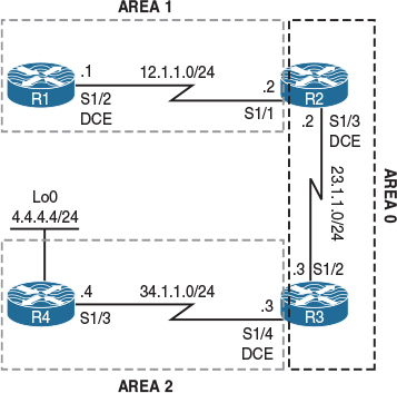
Figure 8-13 LSA Type 4 and Suppress FA
Task 1
Configure OSPF based on the topology shown in Figure 8-13. R4 should redistribute its loopback0 interface into the OSPF routing domain. Configure router IDs of 0.0.0.1, 0.0.0.2, 0.0.0.3, and 0.0.0.4 for R1, R2, R3, and R4, respectively.
On R1:
R1(config)# router ospf 1
R1(config-router)# router-id 0.0.0.1
R1(config-router)# network 12.1.1.1 0.0.0.0 area 1
On R2:
R2(config)# router ospf 1
R2(config-router)# router-id 0.0.0.2
R2(config-router)# network 12.1.1.2 0.0.0.0 area 1
R2(config-router)# network 23.1.1.2 0.0.0.0 area 0
You should see the following console message:
%OSPF-5-ADJCHG: Process 1, Nbr 0.0.0.1 on Serial1/1 from LOADING to FULL,
Loading Done
On R3:
R3(config)# router ospf 1
R3(config-router)# router-id 0.0.0.3
R3(config-router)# network 23.1.1.3 0.0.0.0 area 0
R3(config-router)# network 34.1.1.3 0.0.0.0 area 2
You should see the following console message:
%OSPF-5-ADJCHG: Process 1, Nbr 0.0.0.2 on Serial1/2 from LOADING to FULL,
Loading Done
On R4:
R4(config)# route-map tst
R4(config-route-map)# match interface loopback 0
R4(config)# router ospf 1
R4(config-router)# router-id 0.0.0.4
R4(config-router)# network 34.1.1.4 0.0.0.0 area 2
R4(config-router)# redistribute connected route-map tst subnets
You should see the following console message:
%OSPF-5-ADJCHG: Process 1, Nbr 0.0.0.3 on Serial1/3 from LOADING to FULL,
Loading Done
Let’s verify the configuration:
On R1:
R1# show ip route ospf | begin Gate
Gateway of last resort is not set
4.0.0.0/24 is subnetted, 1 subnets
O E2 4.4.4.0 [110/20] via 12.1.1.2, 00:03:37, Serial1/2
23.0.0.0/24 is subnetted, 1 subnets
O IA 23.1.1.0 [110/1562] via 12.1.1.2, 00:08:13, Serial1/2
34.0.0.0/24 is subnetted, 1 subnets
O IA 34.1.1.0 [110/2343] via 12.1.1.2, 00:06:25, Serial1/2
R1 can see network 4.4.4.0/24. Let’s check the database and see the details of this Type-5 LSA:
R1# show ip ospf database external 4.4.4.0
OSPF Router with ID (0.0.0.1) (Process ID 1)
Type-5 AS External Link States
Routing Bit Set on this LSA in topology Base with MTID 0
LS age: 306
Options: (No TOS-capability, DC)
LS Type: AS External Link
Link State ID: 4.4.4.0 (External Network Number )
Advertising Router: 0.0.0.4
LS Seq Number: 80000001
Checksum: 0x3F51
Length: 36
Network Mask: /24
Metric Type: 2 (Larger than any link state path)
MTID: 0
Metric: 20
Forward Address: 0.0.0.0
External Route Tag: 0
The Link State ID in LSAs Type 3, 5, and 7 describes the actual network. The Advertising Router in this case is R4 (0.0.0.4). The Network Mask for network 4.4.4.0 is /24. Even though the output states Network Mask, in reality it is the prefix length. The Metric Type is 2. This is the default OSPF behavior for redistributed routes, unless this is statically changed to 1 using the metric-type 1 keyword in the redistribute command. The Metric setting (or the cost) is 20. This is the default cost of any redistributed route in OSPF unless it is changed. The Forward Address setting is 0.0.0.0. The forward address is the next hop; when the next hop is set to 0.0.0.0, it means that to reach the next hop, you should go to the advertising router (in this case, 0.0.0.4).
But how do you reach 0.0.0.4? This is not an IP address. This is where LSA Type 4 comes to rescue. Let’s verify this information:
R1# show ip ospf database asbr-summary 0.0.0.4
OSPF Router with ID (0.0.0.1) (Process ID 1)
Summary ASB Link States (Area 1)
Routing Bit Set on this LSA in topology Base with MTID 0
LS age: 925
Options: (No TOS-capability, DC, Upward)
LS Type: Summary Links(AS Boundary Router)
Link State ID: 0.0.0.4 (AS Boundary Router address)
Advertising Router: 0.0.0.2
LS Seq Number: 80000001
Checksum: 0x8293
Length: 28
Network Mask: /0
MTID: 0 Metric: 1562
The Link State ID setting in LSA Type 4 describes the router ID—in this case, the RID of R4, which happens to be an ASBR. The Advertising Router setting is 0.0.0.2, or R2. The Metric setting specifies the cost; the cost to reach 0.0.0.4 is set to 1562. Why 1562? Let’s calculate it.
To calculate the cost, you must add the cost of the serial link that connects R3 to R4 to the cost of the link that connects R2 to R3. Let’s find out the cost of these interfaces:
On R3:
R3# show ip ospf interface serial 1/4 | include Cost
Process ID 1, Router ID 0.0.0.3, Network Type POINT_TO_POINT, Cost: 781
Topology-MTID Cost Disabled Shutdown Topology Name
On R2:
R2# show ip ospf interface serial 1/3 | include Cost
Process ID 1, Router ID 0.0.0.2, Network Type POINT_TO_POINT, Cost: 781
Topology-MTID Cost Disabled Shutdown Topology Name
In other words, 781 + 781 = 1562.
Let’s go to R2 and verify the same information:
Based on the output of the following show command, you can see that the information in LSA Type 5 did not change at all:
On R2:
R2# show ip ospf database external 4.4.4.0
OSPF Router with ID (0.0.0.2) (Process ID 1)
Type-5 AS External Link States
Routing Bit Set on this LSA in topology Base with MTID 0
LS age: 1857
Options: (No TOS-capability, DC)
LS Type: AS External Link
Link State ID: 4.4.4.0 (External Network Number )
Advertising Router: 0.0.0.4
LS Seq Number: 80000001
Checksum: 0x3F51
Length: 36
Network Mask: /24
Metric Type: 2 (Larger than any link state path)
MTID: 0
Metric: 20
Forward Address: 0.0.0.0
External Route Tag: 0
Let’s check LSA Type-4:
R2# show ip ospf database asbr-summary 0.0.0.4
OSPF Router with ID (0.0.0.2) (Process ID 1)
Summary ASB Link States (Area 0)
Routing Bit Set on this LSA in topology Base with MTID 0
LS age: 195
Options: (No TOS-capability, DC, Upward)
LS Type: Summary Links(AS Boundary Router)
Link State ID: 0.0.0.4 (AS Boundary Router address)
Advertising Router: 0.0.0.3
LS Seq Number: 80000002
Checksum: 0xDC47
Length: 28
Network Mask: /0
MTID: 0 Metric: 781
Summary ASB Link States (Area 1)
LS age: 17
Options: (No TOS-capability, DC, Upward)
LS Type: Summary Links(AS Boundary Router)
Link State ID: 0.0.0.4 (AS Boundary Router address)
Advertising Router: 0.0.0.2
LS Seq Number: 80000002
Checksum: 0x8094
Length: 28
Network Mask: /0
MTID: 0 Metric: 1562
As you can see, there are two Type-4 LSAs: One is propagated into Area 0 with a cost of 781, and the second one is propagated into Area 1 with a cost of 1562.
The reason we see two Type-4 LSAs is because R3 injects a Type-4 LSA into Area 0 with the cost of the R3–R4 link, which is 781. R3 does that so the routers in Area 0 will have reachability to the ASBR. R2 is another ABR, so R2 does the same for the routers in Area 1; otherwise, they won’t have reachability to the ASBR.
Now that you know how Type-4 LSAs provide reachability to the ASBR, let’s convert Area 2 to an NSSA area:
On R3 and R4:
Rx(config)# router ospf 1
Rx(config-router)# area 2 nssa
Let’s verify the routing table and the database on R1 and see the difference:
On R1
R1# show ip route ospf | begin Gate
Gateway of last resort is not set
4.0.0.0/24 is subnetted, 1 subnets
O E2 4.4.4.0 [110/20] via 12.1.1.2, 00:00:47, Serial1/2
23.0.0.0/24 is subnetted, 1 subnets
O IA 23.1.1.0 [110/1562] via 12.1.1.2, 00:49:29, Serial1/2
34.0.0.0/24 is subnetted, 1 subnets
O IA 34.1.1.0 [110/2343] via 12.1.1.2, 00:47:41, Serial1/2
Based on the output of the preceding show command, there’s no change from the routing table’s perspective. Let’s view the external database of R1:
R1# show ip ospf database external 4.4.4.0
OSPF Router with ID (0.0.0.1) (Process ID 1)
Type-5 AS External Link States
Routing Bit Set on this LSA in topology Base with MTID 0
LS age: 143
Options: (No TOS-capability, DC)
LS Type: AS External Link
Link State ID: 4.4.4.0 (External Network Number )
Advertising Router: 0.0.0.3
LS Seq Number: 80000001
Checksum: 0xE5B
Length: 36
Network Mask: /24
Metric Type: 2 (Larger than any link state path)
MTID: 0
Metric: 20
Forward Address: 34.1.1.4
External Route Tag: 0
The output of the preceding show command reveals that the advertising router is 0.0.0.3, which is R3. Once Area 1 was converted to an NSSA area, the ASBR (R4) originated the external routes in Type-7 LSAs and then the ABR (R3) received a Type-7 LSA and converted it to LSA Type 5. Therefore, it became a pseudo-ASBR, and this is why the advertising router is set based on R3. The final change is the forward address (FA), or the next hop. It is now set to the IP address of R4 (34.1.1.4). Because the FA is set to the actual IP address of R4, there is no requirement to propagate a Type-4 LSA into Area 0. Let’s verify the Type-4 LSA on R1:
R1# show ip ospf database asbr-summary 0.0.0.3
OSPF Router with ID (0.0.0.1) (Process ID 1)
Summary ASB Link States (Area 1)
Routing Bit Set on this LSA in topology Base with MTID 0
LS age: 520
Options: (No TOS-capability, DC, Upward)
LS Type: Summary Links(AS Boundary Router)
Link State ID: 0.0.0.3 (AS Boundary Router address)
Advertising Router: 0.0.0.2
LS Seq Number: 80000001
Checksum: 0xEE38
Length: 28
Network Mask: /0
MTID: 0 Metric: 781
Note In the preceding output, you can see that R3 is stated as an ASBR. The reason is because R3 is originating an LSA Type 5, and to reach this ASBR you need to go to R2 (0.0.0.2).
Let’s go to R2 and verify the same information:
On R2:
R2# show ip ospf database external 4.4.4.0
OSPF Router with ID (0.0.0.2) (Process ID 1)
Type-5 AS External Link States
Routing Bit Set on this LSA in topology Base with MTID 0
LS age: 726
Options: (No TOS-capability, DC)
LS Type: AS External Link
Link State ID: 4.4.4.0 (External Network Number )
Advertising Router: 0.0.0.3
LS Seq Number: 80000001
Checksum: 0xE5B
Length: 36
Network Mask: /24
Metric Type: 2 (Larger than any link state path)
MTID: 0
Metric: 20
Forward Address: 34.1.1.4
External Route Tag: 0
Let’s verify the Type-4 LSA:
R2# show ip ospf database asbr-summary
OSPF Router with ID (0.0.0.2) (Process ID 1)
Summary ASB Link States (Area 1)
LS age: 843
Options: (No TOS-capability, DC, Upward)
LS Type: Summary Links(AS Boundary Router)
Link State ID: 0.0.0.3 (AS Boundary Router address)
Advertising Router: 0.0.0.2
LS Seq Number: 80000001
Checksum: 0xEE38
Length: 28
Network Mask: /0
MTID: 0 Metric: 781
Note The only Type-4 LSA is propagated in Area 1. Because R3 is claiming to be an ASBR, there is no need to propagate a Type-4 LSA to provide reachability to R3, because R3 has an interface in Area 0.
What will happen if the link that connects R3 to R4 is filtered? Will R1 have network 4.4.4.0/24 in its routing table? Let’s verify:
On R3:
R3(config)# router ospf 1
R3(config-router)# area 2 range 34.1.1.0 255.255.255.0 not-advertise
So if R1 does not have reachability to network 34.1.1.0/24, then it shouldn’t have reachability to a host (34.1.1.4, the FA) on that network. If this is the case, then R1 should not have network 4.4.4.0/24 in its routing table. Let’s verify:
On R1
R1# show ip route ospf | begin Gate
Gateway of last resort is not set
23.0.0.0/24 is subnetted, 1 subnets
O IA 23.1.1.0 [110/1562] via 12.1.1.2, 01:09:46, Serial1/2
Sure enough, R1 does not have network 4.4.4.0/24 in its routing table.
What if the FA is changed to R3? Will R1 have the external route in its routing table? It should because R1 has reachability to R3. Let’s verify.
You need to change the FA to R3. The following command instructs R3 to translate Type-7 LSAs to Type-5 LSAs but to suppress the FA:
On R3
R3(config)# router ospf 1
R3(config-router)# area 2 nssa translate type7 suppress-fa
Let’s verify the configuration:
On R1
R1# show ip route ospf | begin Gate
Gateway of last resort is not set
4.0.0.0/24 is subnetted, 1 subnets
O E2 4.4.4.0 [110/20] via 12.1.1.2, 00:00:14, Serial1/2
23.0.0.0/24 is subnetted, 1 subnets
O IA 23.1.1.0 [110/1562] via 12.1.1.2, 01:15:10, Serial1/2
Does R1 have reachability to 34.1.1.4?
R1# ping 4.4.4.4
Type escape sequence to abort.
Sending 5, 100-byte ICMP Echos to 4.4.4.4, timeout is 2 seconds:
!!!!!
Success rate is 100 percent (5/5), round-trip min/avg/max = 160/160/160 ms
This can be used in certain designs to save resources on the routers. Imagine that there is a hub-and-spoke topology with 1000 spokes, and each spoke is redistributing a single external route. The routers upstream to the hub router will have 2000 routes in their routing table: 1000 routes for the links that connect the hub to the spokes, and another 1000 external routes.
If the spokes are all converted into an NSSA area, and the links that connect the hub to the spokes are all filtered, then the hub router is configured to suppress the FA, and the routers upstream to the hub router will only have 1000 external routes in their routing table, thus saving resources.
Erase the startup configuration and reload the routers before proceeding to the next lab.
Lab 8-13: Can OSPF Take a Suboptimal Path?
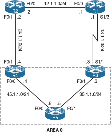
Figure 8-14 Can OSPF Take a Suboptimal Path?
Task 1
Configure OSPF Area 0 on R3, R4, and R5 based on the following policies:
![]() These routers should run OSPF Area 0 on all existing and future directly connected interfaces.
These routers should run OSPF Area 0 on all existing and future directly connected interfaces.
![]() Configure the RIDs to be 0.0.0.3, 0.0.0.4, and 0.0.0.5 for R3, R4, and R5, respectively.
Configure the RIDs to be 0.0.0.3, 0.0.0.4, and 0.0.0.5 for R3, R4, and R5, respectively.
On R3:
R3(config)# router ospf 1
R3(config-router)# router-id 0.0.0.3
R3(config-router)# network 0.0.0.0 0.0.0.0 area 0
On R4:
R4(config)# router ospf 1
R4(config-router)# router-id 0.0.0.4
R4(config-router)# network 0.0.0.0 0.0.0.0 area 0
On R5:
R5(config)# router ospf 1
R5(config-router)# router-id 0.0.0.5
R5(config-router)# network 0.0.0.0 0.0.0.0 area 0
You should see the following console messages:
%OSPF-5-ADJCHG: Process 1, Nbr 0.0.0.4 on FastEthernet0/0 from LOADING to FULL,
Loading Done
%OSPF-5-ADJCHG: Process 1, Nbr 0.0.0.3 on FastEthernet0/1 from LOADING to FULL,
Loading Done
Let’s verify the configuration:
On R5:
R5# show ip ospf neighbor
Neighbor ID Pri State Dead Time Address Interface
0.0.0.3 1 FULL/DR 00:00:33 35.1.1.3 FastEthernet0/1
0.0.0.4 1 FULL/BDR 00:00:32 45.1.1.4 FastEthernet0/0
Task 2
Configure the following policies on the routers in the topology shown in Figure 8-14:
![]() Configure a static default route on R1 pointing to R3 (13.1.1.3).
Configure a static default route on R1 pointing to R3 (13.1.1.3).
![]() Configure a static default route on R2 pointing to R4 (24.1.1.4).
Configure a static default route on R2 pointing to R4 (24.1.1.4).
![]() Configure a static route for network 12.1.1.0/24 on R3 pointing to R1 (13.1.1.1) and redistribute this static route into the OSPF routing domain using metric type 1.
Configure a static route for network 12.1.1.0/24 on R3 pointing to R1 (13.1.1.1) and redistribute this static route into the OSPF routing domain using metric type 1.
![]() Configure a static route for network 12.1.1.0/24 on R4 pointing to R2 (24.1.1.2) and redistribute this static route into the OSPF routing domain using metric type 1.
Configure a static route for network 12.1.1.0/24 on R4 pointing to R2 (24.1.1.2) and redistribute this static route into the OSPF routing domain using metric type 1.
On R1
R1(config)# ip route 0.0.0.0 0.0.0.0 13.1.1.3
On R3
R3(config)# ip route 12.1.1.0 255.255.255.0 13.1.1.1
R3(config)# router ospf 1
R3(config-router)# redistribute static subnets metric-type 1
On R4
R4(config)# ip route 12.1.1.0 255.255.255.0 24.1.1.2
R4(config)# Router ospf 1
R4(config-router)# redistribute static subnets metric-type 1
Let’s verify the configuration:
On R5:
R5# show ip route ospf | begin Gate
Gateway of last resort is not set
12.0.0.0/24 is subnetted, 1 subnets
O E1 12.1.1.0 [110/21] via 35.1.1.3, 00:01:13, FastEthernet0/1
13.0.0.0/24 is subnetted, 1 subnets
O 13.1.1.0 [110/782] via 35.1.1.3, 00:05:39, FastEthernet0/1
24.0.0.0/24 is subnetted, 1 subnets
O 24.1.1.0 [110/2] via 45.1.1.4, 00:05:10, FastEthernet0/0
R5 has two ways to reach network 12.1.1.0/24: one through R4, in which case it has to traverse through two FastEthernet links, and the other through R3, in which case it has to traverse the FastEthernet and a serial link. Why is R5 taking a suboptimal path through R3?
Let’s verify R5’s cost to the two ASBRs (R3 and R4):
R5# Show ip ospf border-routers
OSPF Process 1 internal Routing Table
Codes: i - Intra-area route, I - Inter-area route
i 0.0.0.3 [1] via 35.1.1.3, FastEthernet0/1, ASBR, Area 0, SPF 5
i 0.0.0.4 [1] via 45.1.1.4, FastEthernet0/0, ASBR, Area 0, SPF 5
You can see that R5 has a cost of 1 to reach both ASBRs, R3 (0.0.0.3) and R4 (0.0.0.4), and by default when the ASBRs redistribute external routes, they assign a cost of 20. Therefore, the cost should be 21 through both ASBRs, so why is R5 taking R3?
Let’s verify the cost for the s1/1 interface of R3:
On R3:
R3# show ip ospf interface serial 1/1 | include Cost
Process ID 1, Router ID 0.0.0.3, Network Type POINT_TO_POINT, Cost: 781
Topology-MTID Cost Disabled Shutdown Topology Name
Let’s verify the cost for the f0/1 interface of R4:
On R4:
R4# show ip ospf interface FastEthernet0/1 | include Cost
Process ID 1, Router ID 0.0.0.4, Network Type BROADCAST, Cost: 1
Topology-MTID Cost Disabled Shutdown Topology Name
The cost is lower through R4, but R5 is taking R3 to reach network 12.1.1.0/24.
Let’s shut down the F0/1 interface of R5 and see if R5 will go through R4 to reach 12.1.1.0/24:
R5(config)# int FastEthernet0/1
R5(config-if)# shutdown
R5# Show ip route ospf | begin Gate
Gateway of last resort is not set
12.0.0.0/24 is subnetted, 1 subnets
O E1 12.1.1.0 [110/22] via 45.1.1.4, 00:00:15, FastEthernet0/0
24.0.0.0/24 is subnetted, 1 subnets
O 24.1.1.0 [110/2] via 45.1.1.4, 00:18:16, FastEthernet0/0
R5’s cost to R4 is 1, and R4 is redistributing the external routes with a default cost of 20. This should be 21 and not 22. Let’s use no shutdown on the F0/1 interface of R5 and check the Link State Database (LSDB) of this router:
On R5
R5(config)# interface FastEthernet0/1
R5(config-if)# no shutdown
R5# show ip ospf database external 12.1.1.0
OSPF Router with ID (0.0.0.5) (Process ID 1)
Type-5 AS External Link States
Routing Bit Set on this LSA in topology Base with MTID 0
LS age: 1895
Options: (No TOS-capability, DC)
LS Type: AS External Link
Link State ID: 12.1.1.0 (External Network Number )
Advertising Router: 0.0.0.3
LS Seq Number: 80000001
Checksum: 0x9E71
Length: 36
Network Mask: /24
Metric Type: 1 (Comparable directly to link state metric)
MTID: 0
Metric: 20
Forward Address: 0.0.0.0
External Route Tag: 0
LS age: 1857
Options: (No TOS-capability, DC)
LS Type: AS External Link
Link State ID: 12.1.1.0 (External Network Number )
Advertising Router: 0.0.0.4
LS Seq Number: 80000001
Checksum: 0xD61C
Length: 36
Network Mask: /24
Metric Type: 1 (Comparable directly to link state metric)
MTID: 0
Metric: 20
Forward Address: 24.1.1.2
External Route Tag: 0
Okay, you can see the problem: R4 has set the FA to 24.1.1.2; therefore, the cost is calculated from R5 all the way to R2’s F0/1 interface, whereas the FA from R3 is set to R3 (0.0.0.0). Let’s calculate the cost:
![]() The cost through R3: R3 is advertising an FA of 0.0.0.0; therefore, R5 calculates the cost right up to R3. R3 redistributes the static route with a default cost of 20. R5’s cost to R3 is 1. Therefore, the cost through R3 is 21.
The cost through R3: R3 is advertising an FA of 0.0.0.0; therefore, R5 calculates the cost right up to R3. R3 redistributes the static route with a default cost of 20. R5’s cost to R3 is 1. Therefore, the cost through R3 is 21.
![]() The cost through R4: R4 is advertising an FA of 24.1.1.2; therefore, R5 calculates the cost right up to R2’s f0/1 interface. R5 redistributes the static route with a default cost of 20. R5’s cost to R4 is 1, and R4’s cost to R2 is also 1. Therefore, R5’s cost through R4 is 22.
The cost through R4: R4 is advertising an FA of 24.1.1.2; therefore, R5 calculates the cost right up to R2’s f0/1 interface. R5 redistributes the static route with a default cost of 20. R5’s cost to R4 is 1, and R4’s cost to R2 is also 1. Therefore, R5’s cost through R4 is 22.
The question is, Why?
The answer is the network type. R4’s external interface to R2 has a network type of broadcast. Let’s verify:
R4# show ip ospf interface FastEthernet0/1 | include Network
Process ID 1, Router ID 0.0.0.4, Network Type BROADCAST, Cost: 1
Because on a broadcast network we can have many neighbors, the next-hop/FA is set based on the advertising router’s IP address (in this case, 24.1.1.2).
Let’s verify the network type of the s1/1 interface of R3:
R3# show ip ospf interface serial 1/1 | include Network
Process ID 1, Router ID 0.0.0.3, Network Type POINT_TO_POINT, Cost: 64
Because the network type is set to be point-to-point, R3 simply says there is only one potential neighbor, so it sets the NH/FA to its interface’s IP address.
Let’s change the network types on the external interfaces of R3 and R4 such that R5 takes an optimal path to reach 12.1.1.0/24. To accomplish this, the network types are swapped:
On R4:
R4(config)# interface FastEthernet0/1
R4(config-if)# ip ospf network point-to-point
Let’s verify the configuration:
On R5:
R5# show ip route ospf | begin Gate
Gateway of last resort is not set
12.0.0.0/24 is subnetted, 1 subnets
O E1 12.1.1.0 [110/21] via 45.1.1.4, 00:00:28, FastEthernet0/0
13.0.0.0/24 is subnetted, 1 subnets
O 13.1.1.0 [110/782] via 35.1.1.3, 00:16:28, FastEthernet0/1
24.0.0.0/24 is subnetted, 1 subnets
O 24.1.1.0 [110/2] via 45.1.1.4, 00:51:40, FastEthernet0/0
R5# show ip ospf database external 12.1.1.0 | include Advertising|Forward
Advertising Router: 0.0.0.3
Forward Address: 13.1.1.1
Advertising Router: 0.0.0.4
Forward Address: 0.0.0.0
Erase the startup configuration of the routers and reload them before proceeding to the next lab.
Lab 8-14: RFC 3101 and RFC 1587
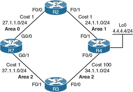
Figure 8-15 RFC 3101 and RFC 1587
Task 1
Configure OSPF based on the topology shown in Figure 8-15. R4 should be configured to redistribute its loopback0 interface in this routing domain using the default parameters. The router IDs should be configured as 0.0.0.x, where x is the router number. Explain which path R7 takes to reach network 4.4.4.0/24.
On R7:
R7(config)# router ospf 1
R7(config-router)# router-id 0.0.0.7
R7(config-router)# network 27.1.1.7 0.0.0.0 area 0
R7(config-router)# network 37.1.1.7 0.0.0.0 area 2
On R2:
R2(config)# router ospf 1
R2(config-router)# router-id 0.0.0.2
R2(config-router)# network 27.1.1.2 0.0.0.0 area 0
R2(config-router)# network 24.1.1.2 0.0.0.0 area 1
You should see the following console message:
%OSPF-5-ADJCHG: Process 1, Nbr 0.0.0.7 on FastEthernet0/0 from LOADING to FULL,
Loading Done
On R3:
R3(config)# router ospf 1
R3(config-router)# router-id 0.0.0.3
R3(config-router)# network 37.1.1.3 0.0.0.0 area 2
R3(config-router)# network 34.1.1.3 0.0.0.0 area 2
You should see the following console message as well:
%OSPF-5-ADJCHG: Process 1, Nbr 0.0.0.7 on FastEthernet0/1 from LOADING to FULL,
Loading Done
On R4:
R4(config)# route-map tst
R4(config-route-map)# match interface loopback 0
R4(config)# router ospf 1
R4(config-router)# router-id 0.0.0.4
R4(config-router)# network 34.1.1.4 0.0.0.0 area 2
R4(config-router)# network 24.1.1.4 0.0.0.0 area 1
R4(config-router)# redistribute connected route-map tst subnets
You should also see the following console messages:
%OSPF-5-ADJCHG: Process 1, Nbr 0.0.0.3 on FastEthernet0/0 from LOADING to FULL,
Loading Done
%OSPF-5-ADJCHG: Process 1, Nbr 0.0.0.2 on FastEthernet0/1 from LOADING to FULL,
Loading Done
Let’s verify the configuration:
On R7:
R7# show ip route ospf | begin Gate
Gateway of last resort is not set
4.0.0.0/24 is subnetted, 1 subnets
O E2 4.4.4.0 [110/20] via 37.1.1.3, 00:00:11, GigabitEthernet0/1
24.0.0.0/24 is subnetted, 1 subnets
O IA 24.1.1.0 [110/2] via 27.1.1.2, 00:02:07, GigabitEthernet0/0
34.0.0.0/24 is subnetted, 1 subnets
O 34.1.1.0 [110/101] via 37.1.1.3, 00:01:15, GigabitEthernet0/1
We can see that R7 takes the path through R3 to reach network 4.4.4.0/24. But why? Let’s check R7’s route to network 4.4.4.0/24:
R7# show ip route 4.4.4.0
Routing entry for 4.4.4.0/24
Known via "ospf 1", distance 110, metric 20, type extern 2, forward metric 101
Last update from 37.1.1.3 on GigabitEthernet0/1, 00:01:19 ago
Routing Descriptor Blocks:
* 37.1.1.3, from 0.0.0.4, 00:01:19 ago, via GigabitEthernet0/1
Route metric is 20, traffic share count is 1
Let’s check the LSDB of R7 for network 4.4.4.0/24:
R7# show ip ospf database external 4.4.4.0
OSPF Router with ID (0.0.0.1) (Process ID 1)
Type-5 AS External Link States
Routing Bit Set on this LSA in topology Base with MTID 0
LS age: 170
Options: (No TOS-capability, DC, Upward)
LS Type: AS External Link
Link State ID: 4.4.4.0 (External Network Number )
Advertising Router: 0.0.0.4
LS Seq Number: 80000001
Checksum: 0x3F51
Length: 36
Network Mask: /24
Metric Type: 2 (Larger than any link state path)
MTID: 0
Metric: 20
Forward Address: 0.0.0.0
External Route Tag: 0
The output of the preceding show command reveals the following:
![]() The link state ID, which describes the network as 4.4.4.0.
The link state ID, which describes the network as 4.4.4.0.
![]() The advertising router is 0.0.0.4, or R4.
The advertising router is 0.0.0.4, or R4.
![]() The metric type is 2. This is the default behavior in OSPF.
The metric type is 2. This is the default behavior in OSPF.
![]() The forward address is set to 0.0.0.0, meaning that R4 is the next hop.
The forward address is set to 0.0.0.0, meaning that R4 is the next hop.
R7 has two paths to reach network 4.4.4.0/24:
![]() An intra-area route via R3 with a cost of 101: This cost is displayed in the output of the show ip route 4.4.4.0 command as the forward metric.
An intra-area route via R3 with a cost of 101: This cost is displayed in the output of the show ip route 4.4.4.0 command as the forward metric.
![]() An inter-area route via R2 with a cost of 2: From R7’s perspective, this is the cumulative cost of reaching R2 (the ABR), which is 1, plus the ABR’s cost to reach R4, which is also 1. Therefore, the total cost is 2. We can see the cost by looking at the Type-4 LSA that is injected by the ABR (R2) and/or by using the show ip ospf border-routers command:
An inter-area route via R2 with a cost of 2: From R7’s perspective, this is the cumulative cost of reaching R2 (the ABR), which is 1, plus the ABR’s cost to reach R4, which is also 1. Therefore, the total cost is 2. We can see the cost by looking at the Type-4 LSA that is injected by the ABR (R2) and/or by using the show ip ospf border-routers command:
R7# show ip ospf border-routers
OSPF Router with ID (0.0.0.1) (Process ID 1)
Base Topology (MTID 0)
Internal Router Routing Table
Codes: i - Intra-area route, I - Inter-area route
i 0.0.0.2 [1] via 27.1.1.2, GigabitEthernet0/0, ABR, Area 0, SPF 4
i 0.0.0.4 [101] via 37.1.1.3, GigabitEthernet0/1, ASBR, Area 2, SPF 8
R7# show ip ospf database asbr-summary adv-router 0.0.0.2
OSPF Router with ID (0.0.0.1) (Process ID 1)
Summary ASB Link States (Area 0)
LS age: 1616
Options: (No TOS-capability, DC, Upward)
LS Type: Summary Links(AS Boundary Router)
Link State ID: 0.0.0.4 (AS Boundary Router address)
Advertising Router: 0.0.0.2
LS Seq Number: 80000001
Checksum: 0x51E3
Length: 28
Network Mask: /0
MTID: 0 Metric: 1
Let’s traceroute to 4.4.4.4 and verify the path:
R7# traceroute 4.4.4.4 numeric
Type escape sequence to abort.
Tracing the route to 4.4.4.4
VRF info: (vrf in name/id, vrf out name/id)
1 37.1.1.3 4 msec 0 msec 4 msec
2 34.1.1.4 0 msec * 0 msec
In OSPF, intra-area routes are preferred over inter-area routes. R7 takes the intra-area route versus inter-area route to reach 4.4.4.0/24.
Task 2
Convert Areas 1 and 2 to NSSA. Once the areas are converted to NSSA, describe the path that R7 takes to reach network 4.4.4.0/24.
On R7, R3, and R4:
Rx(config)# router ospf 1
Rx(config-router)# area 2 nssa
On R2, and R4:
Rx(config)# router ospf 1
Rx(config-router)# area 1 nssa
Let’s verify the configuration:
On R7:
R7# show ip route ospf | begin Gate
Gateway of last resort is not set
4.0.0.0/24 is subnetted, 1 subnets
O E2 4.4.4.0 [110/20] via 27.1.1.2, 00:00:41, GigabitEthernet0/0
24.0.0.0/24 is subnetted, 1 subnets
O IA 24.1.1.0 [110/2] via 27.1.1.2, 00:01:43, GigabitEthernet0/0
34.0.0.0/24 is subnetted, 1 subnets
O 34.1.1.0 [110/101] via 37.1.1.3, 00:01:00, GigabitEthernet0/1
R7# show ip route 4.4.4.0
Routing entry for 4.4.4.0/24
Known via "ospf 1", distance 110, metric 20, type extern 2, forward metric 2
Last update from 27.1.1.2 on GigabitEthernet0/0, 00:01:18 ago
Routing Descriptor Blocks:
* 27.1.1.2, from 0.0.0.2, 00:01:18 ago, via GigabitEthernet0/0
Route metric is 20, traffic share count is 1
Why is R7 installing an “E2” route through R2 and not an “N2” route through R3?
R4 advertises two Type-7 LSAs:
![]() A Type-7 LSA with a forward address of 24.1.1.4. This is the IP address of R4’s F0/1 interface, and this LSA is flooded into Area 1. The ABR (R2) translates this Type-7 LSA into a Type-5 LSA, copies the forward address from LSA Type 7 into LSA Type 5, and floods it into Area 0.
A Type-7 LSA with a forward address of 24.1.1.4. This is the IP address of R4’s F0/1 interface, and this LSA is flooded into Area 1. The ABR (R2) translates this Type-7 LSA into a Type-5 LSA, copies the forward address from LSA Type 7 into LSA Type 5, and floods it into Area 0.
![]() A Type-7 LSA with a forward address of 34.1.1.4. This is R4’s F0/0 interface; it is flooded into Area 2.
A Type-7 LSA with a forward address of 34.1.1.4. This is R4’s F0/0 interface; it is flooded into Area 2.
R7# show ip ospf database external 4.4.4.0
OSPF Router with ID (0.0.0.1) (Process ID 1)
Type-5 AS External Link States
Routing Bit Set on this LSA in topology Base with MTID 0
LS age: 552
Options: (No TOS-capability, DC)
LS Type: AS External Link
Link State ID: 4.4.4.0 (External Network Number )
Advertising Router: 0.0.0.2
LS Seq Number: 80000001
Checksum: 0xA5CE
Length: 36
Network Mask: /24
Metric Type: 2 (Larger than any link state path)
MTID: 0
Metric: 20
Forward Address: 24.1.1.4
External Route Tag: 0
R7# show ip ospf database nssa-external 4.4.4.0
OSPF Router with ID (0.0.0.1) (Process ID 1)
Type-7 AS External Link States (Area 2)
LS age: 659
Options: (No TOS-capability, Type 7/5 translation, DC)
LS Type: AS External Link
Link State ID: 4.4.4.0 (External Network Number )
Advertising Router: 0.0.0.4
LS Seq Number: 80000002
Checksum: 0x71EB
Length: 36
Network Mask: /24
Metric Type: 2 (Larger than any link state path)
MTID: 0
Metric: 20
Forward Address: 34.1.1.4
External Route Tag: 0
R7 chooses the best path to reach the two forward addresses using an intra-area route (through R3) and an inter-area route (through R2):
R7# show ip route 24.1.1.4
Routing entry for 24.1.1.0/24
Known via "ospf 1", distance 110, metric 2, type inter area
Last update from 27.1.1.2 on GigabitEthernet0/0, 00:06:32 ago
Routing Descriptor Blocks:
* 27.1.1.2, from 0.0.0.2, 00:06:32 ago, via GigabitEthernet0/0
Route metric is 2, traffic share count is 1
R7# show ip route 34.1.1.4
Routing entry for 34.1.1.0/24
Known via "ospf 1", distance 110, metric 101, type intra area
Last update from 37.1.1.3 on GigabitEthernet0/1, 00:06:24 ago
Routing Descriptor Blocks:
* 37.1.1.3, from 0.0.0.4, 00:06:24 ago, via GigabitEthernet0/1
Route metric is 101, traffic share count is 1
Because the two OSPF routes (intra-area and inter-area) are pointing to different destinations, R7 can no longer prefer the intra-area route over the inter-area route. Therefore, R7 chooses the lowest cost through R2. Let’s verify:
R1# traceroute 4.4.4.4 numeric
Type escape sequence to abort.
Tracing the route to 4.4.4.4
VRF info: (vrf in name/id, vrf out name/id)
1 27.1.1.2 4 msec 0 msec 0 msec
2 24.1.1.4 0 msec * 0 msec
To prove this, let’s change the cost of R7’s link to R2 to 200:
R7(config)# int GigabitEthernet0/0
R7(config-if)# ip ospf cost 200
Let’s verify the configuration:
R71# traceroute 4.4.4.4 numeric
Type escape sequence to abort.
Tracing the route to 4.4.4.4
VRF info: (vrf in name/id, vrf out name/id)
1 37.1.1.3 0 msec 0 msec 0 msec
2 34.1.1.4 4 msec * 0 msec
The following show command displays that the “N” route is preferred over the “E” route:
R7# show ip route ospf | begin Gate
Gateway of last resort is not set
4.0.0.0/24 is subnetted, 1 subnets
O N2 4.4.4.0 [110/20] via 37.1.1.3, 00:01:08, GigabitEthernet0/1
24.0.0.0/24 is subnetted, 1 subnets
O IA 24.1.1.0 [110/201] via 27.1.1.2, 00:01:08, GigabitEthernet0/0
34.0.0.0/24 is subnetted, 1 subnets
O 34.1.1.0 [110/101] via 37.1.1.3, 00:13:08, GigabitEthernet0/1
Let’s reconfigure the cost on R7’s g0/0 as well as R3 and R4’s f0/0 to 1. This way, from R7’s perspective, the cost will be identical no matter which path R7 takes:
On R3 and R4:
Rx(config)# interface FastEthernet0/0
Rx(config-if)# ip ospf cost 1
Let’s verify the configuration:
On R7:
R7# show ip route ospf | begin Gate
Gateway of last resort is not set
4.0.0.0/24 is subnetted, 1 subnets
O N2 4.4.4.0 [110/20] via 37.1.1.3, 00:01:10, GigabitEthernet0/1
24.0.0.0/24 is subnetted, 1 subnets
O IA 24.1.1.0 [110/2] via 27.1.1.2, 00:03:05, GigabitEthernet0/0
34.0.0.0/24 is subnetted, 1 subnets
O 34.1.1.0 [110/2] via 37.1.1.3, 00:01:10, GigabitEthernet0/1
In this case, the cost from R7’s perspective is identical no matter which path it takes, but R7 is taking the “N” route over the “E” route. Why?
Let’s verify:
On R7:
R7# show ip ospf | include RFC
Supports NSSA (compatible with RFC 3101)
You can see that R7 is implementing RFC 3101. RFC 3101 states the following: If the current LSA is functionally the same as an installed LSA (that is, same destination, cost, and non-zero forwarding address), then apply the following priorities in deciding which LSA is preferred:
1. A Type-7 LSA with the P-bit set.
2. A Type-5 LSA.
3. The LSA with the higher router ID.
Let’s see if the P-bit is set:
R7# Show ip ospf database nssa-external 4.4.4.0
OSPF Router with ID (0.0.0.7) (Process ID 1)
Type-7 AS External Link States (Area 2)
Routing Bit Set on this LSA in topology Base with MTID 0
LS age: 1670
Options: (No TOS-capability, Type 7/5 translation, DC, Upward)
LS Type: AS External Link
Link State ID: 4.4.4.0 (External Network Number )
Advertising Router: 0.0.0.4
LS Seq Number: 80000001
Checksum: 0x73EA
Length: 36
Network Mask: /24
Metric Type: 2 (Larger than any link state path)
MTID: 0
Metric: 20
Forward Address: 34.1.1.4
External Route Tag: 0
What if RFC 1587 is implemented? RFC 1587 states the following: When a Type-5 LSA and a Type-7 LSA are found to have the same type and an equal distance, the following priorities apply (listed from highest to lowest) for breaking the tie:
1. Any Type-5 LSA.
2. A Type-7 LSA with the P-bit set and a non-zero forwarding address.
3. Any other Type-7 LSA.
Let’s change the RFC to implement RFC 1587:
R7(config)# router ospf 1
R7(config-router)# compatible rfc1587
Note To implement RFC 3101, the preceding command must be negated.
Let’s verify the configuration:
On R7:
R7# show ip route ospf | begin Gate
Gateway of last resort is not set
4.0.0.0/24 is subnetted, 1 subnets
O E2 4.4.4.0 [110/20] via 27.1.1.2, 00:01:35, GigabitEthernet0/0
24.0.0.0/24 is subnetted, 1 subnets
O IA 24.1.1.0 [110/2] via 27.1.1.2, 00:19:18, GigabitEthernet0/0
34.0.0.0/24 is subnetted, 1 subnets
O 34.1.1.0 [110/2] via 37.1.1.3, 00:17:23, GigabitEthernet0/1
Erase the startup configuration of the routers and reload them before proceeding to the next lab.