Chapter 7 EIGRP
This chapter focuses on the commands and methodologies necessary to deploy the Enhanced Interior Gateway Routing Protocol (EIGRP) in a Cisco Routing and Switching environment. Each section of this chapter covers a critical aspect of deploying EIGRP.
Lab 7-1: EIGRP
Note Before proceeding with this lab, you need to copy and paste the running configuration information found in the Lab7-1_EIGRP.txt file. Once these configurations have been installed, you may proceed with Task 1.
Task 1
First, we have to enable ip routing on SW1 itself. This enables the device to provide the services necessary to emulate the behavior of the Internet in this lab. Second, we have to configure static routes pointing to the corresponding interfaces on SW1.
!On SW1:
SW1(config)# ip routing
Now that we have enabled ip routing on SW1, we need to configure the prescribed static default routes specified in the task:
!On R1:
R1(config)# ip route 0.0.0.0 0.0.0.0 200.1.1.10
!On R2:
R2(config)# ip route 0.0.0.0 0.0.0.0 200.1.2.10
!On R3:
R3(config)# ip route 0.0.0.0 0.0.0.0 200.1.3.10
!On R4:
R4(config)# ip route 0.0.0.0 0.0.0.0 200.1.4.10

Figure 7-1 Running EIGRP over DMVPN Lab Topology
Figure 7-1 shows the topology we will use to explore running EIGRP across a Dynamic Multi-point Virtual Private Network (DMVPN) cloud. In this topology, SW1 represents the Internet. We have configured a static default route on each router pointing to the appropriate interface on SW1. If this configuration has been performed correctly, these routers should be able to ping and have reachability to the F0/0 interfaces of all routers in this topology. The switch interface to which the routers are connected will have “.10” in the host portion of the IP address for that subnet. We can verify this essential reachability as follows:
!On R1:
R1# ping 200.1.2.2
Type escape sequence to abort.
Sending 5, 100-byte ICMP Echos to 192.1.2.2, timeout is 2 seconds:
!!!!!
Success rate is 100 percent (5/5), round-trip min/avg/max = 1/2/4 ms
R1# ping 200.1.3.3
Type escape sequence to abort.
Sending 5, 100-byte ICMP Echos to 192.1.3.3, timeout is 2 seconds:
!!!!!
Success rate is 100 percent (5/5), round-trip min/avg/max = 1/2/4 ms
R1# ping 200.1.4.4
Type escape sequence to abort.
Sending 5, 100-byte ICMP Echos to 192.1.4.4, timeout is 2 seconds:
!!!!!
Success rate is 100 percent (5/5), round-trip min/avg/max = 1/2/4 ms
!On R2:
R2# ping 200.1.3.3
Type escape sequence to abort.
Sending 5, 100-byte ICMP Echos to 192.1.3.3, timeout is 2 seconds:
!!!!!
Success rate is 100 percent (5/5), round-trip min/avg/max = 1/2/4 ms
R2# ping 200.1.4.4
Type escape sequence to abort.
Sending 5, 100-byte ICMP Echos to 192.1.4.4, timeout is 2 seconds:
!!!!!
Success rate is 100 percent (5/5), round-trip min/avg/max = 1/1/4 ms
!On R3:
R3# ping 200.1.4.4
Type escape sequence to abort.
Sending 5, 100-byte ICMP Echos to 200.1.4.4, timeout is 2 seconds:
!!!!!
Success rate is 100 percent (5/5), round-trip min/avg/max = 1/1/4 ms
As you can see, the verifications indicate that we have the necessary reachability across the simulated Internet connection to begin building the DMVPN interconnections.
Task 2
Configure DMVPN Phase 1 such that R1 is the hub. R2, R3, and R4 are configured as the spokes. You should use 10.1.1.x/24, where “x” is the router number for the tunnel IP address. If this configuration is performed correctly, these routers should have reachability to all tunnel endpoints. Do not provide multicast capability.
!On R1:
R1(config)# interface tunnel1
R1(config-if)# ip address 10.1.1.1 255.255.255.0
R1(config-if)# tunnel source 200.1.1.1
R1(config-if)# tunnel mode gre multipoint
R1(config-if)# ip nhrp network-id 111
!On R2:
R2(config)# interface tunnel1
R2(config-if)# ip address 10.1.1.2 255.255.255.0
R2(config-if)# tunnel source 200.1.2.2
R2(config-if)# tunnel destination 200.1.1.1
R2(config-if)# ip nhrp network-id 222
R2(config-if)# ip nhrp nhs 10.1.1.1
R2(config-if)# ip nhrp map 10.1.1.1 200.1.1.1
!On R3:
R3(config)# interface tunnel1
R3(config-if)# ip address 10.1.1.3 255.255.255.0
R3(config-if)# tunnel source 200.1.3.3
R3(config-if)# tunnel destination 200.1.1.1
R3(config-if)# ip nhrp network-id 333
R3(config-if)# ip nhrp nhs 10.1.1.1
R3(config-if)# ip nhrp map 10.1.1.1 200.1.1.1
!On R4:
R4(config)# interface tunnel1
R4(config-if)# ip address 10.1.1.4 255.255.255.0
R4(config-if)# tunnel source 200.1.4.4
R4(config-if)# tunnel destination 200.1.1.1
R4(config-if)# ip nhrp network-id 444
R4(config-if)# ip nhrp nhs 10.1.1.1
R4(config-if)# ip nhrp map 10.1.1.1 200.1.1.1
With this accomplished, we need to verify that the DMVPN cloud is working as expected:
!On R1:
R1# show ip nhrp
10.1.1.2/32 via 10.1.1.2
Tunnel1 created 00:00:31, expire 01:59:58
Type: dynamic, Flags: unique registered used
NBMA address: 200.1.2.2
10.1.1.3/32 via 10.1.1.3
Tunnel1 created 00:00:20, expire 01:59:59
Type: dynamic, Flags: unique registered used
NBMA address: 200.1.3.3
10.1.1.4/32 via 10.1.1.4
Tunnel1 created 00:00:12, expire 01:59:57
Type: dynamic, Flags: unique registered used
NBMA address: 200.1.4.4
R1# ping 10.1.1.2
Type escape sequence to abort.
Sending 5, 100-byte ICMP Echos to 10.1.1.2, timeout is 2 seconds:
!!!!!
Success rate is 100 percent (5/5), round-trip min/avg/max = 1/3/4 ms
R1# ping 10.1.1.3
Type escape sequence to abort.
Sending 5, 100-byte ICMP Echos to 10.1.1.3, timeout is 2 seconds:
!!!!!
Success rate is 100 percent (5/5), round-trip min/avg/max = 1/3/4 ms
R1# ping 10.1.1.4
Type escape sequence to abort.
Sending 5, 100-byte ICMP Echos to 10.1.1.4, timeout is 2 seconds:
!!!!!
Success rate is 100 percent (5/5), round-trip min/avg/max = 1/3/4 ms
!On R2:
R2# ping 10.1.1.3
Type escape sequence to abort.
Sending 5, 100-byte ICMP Echos to 10.1.1.3, timeout is 2 seconds:
!!!!!
Success rate is 100 percent (5/5), round-trip min/avg/max = 1/3/4 ms
R2# ping 10.1.1.4
Type escape sequence to abort.
Sending 5, 100-byte ICMP Echos to 10.1.1.4, timeout is 2 seconds:
!!!!!
Success rate is 100 percent (5/5), round-trip min/avg/max = 1/3/4 ms
!On R3:
R3# ping 10.1.1.4
Type escape sequence to abort.
Sending 5, 100-byte ICMP Echos to 10.1.1.4, timeout is 2 seconds:
!!!!!
Success rate is 100 percent (5/5), round-trip min/avg/max = 1/2/4 ms
Use the traceroute command to see the traffic path between the spokes. Run the command twice to see if there are any changes:
R2# traceroute 10.1.1.3 numeric
Type escape sequence to abort.
Tracing the route to 10.1.1.3
VRF info: (vrf in name/id, vrf out name/id)
1 10.1.1.1 4 msec 4 msec 4 msec
2 10.1.1.3 0 msec * 0 msec
R2# traceroute 10.1.1.3 numeric
Type escape sequence to abort.
Tracing the route to 10.1.1.3
VRF info: (vrf in name/id, vrf out name/id)
1 10.1.1.1 0 msec 4 msec 4 msec
2 10.1.1.3 4 msec * 0 msec
R2# traceroute 10.1.1.4 numeric
Type escape sequence to abort.
Tracing the route to 10.1.1.4
VRF info: (vrf in name/id, vrf out name/id)
1 10.1.1.1 4 msec 4 msec 0 msec
2 10.1.1.4 4 msec * 0 msec
R2# traceroute 10.1.1.4 numeric
Type escape sequence to abort.
Tracing the route to 10.1.1.4
VRF info: (vrf in name/id, vrf out name/id)
1 10.1.1.1 4 msec 4 msec 0 msec
2 10.1.1.4 4 msec * 0 msec
Task 3
Configure EIGRP AS 100 on the tunnel and the loopback interfaces of these routers. You may break one of the rules in the previous task. These routers must use multicast for EIGRP adjacency.
!On R1:
R1(config)# router eigrp 100
R1(config-router)# network 1.1.1.1 0.0.0.0
R1(config-router)# network 10.1.1.1 0.0.0.0
!On R2:
R2(config)# router eigrp 100
R2(config-router)# network 2.2.2.2 0.0.0.0
R2(config-router)# network 10.1.1.2 0.0.0.0
!On R3:
R3(config)# router eigrp 100
R3(config-router)# network 3.3.3.3 0.0.0.0
R3(config-router)# network 10.1.1.3 0.0.0.0
!On R4:
R4(config)# router eigrp 100
R4(config-router)# network 4.4.4.4 0.0.0.0
R4(config-router)# network 10.1.1.4 0.0.0.0
You can see that the adjacency is not stable. On R1, the adjacency keeps on going up and then down:
%DUAL-5-NBRCHANGE: EIGRP-IPv4 100: Neighbor 10.1.1.2 (Tunnel1) is up: new adjacency
%DUAL-5-NBRCHANGE: EIGRP-IPv4 100: Neighbor 10.1.1.3 (Tunnel1) is up: new adjacency
%DUAL-5-NBRCHANGE: EIGRP-IPv4 100: Neighbor 10.1.1.4 (Tunnel1) is up: new adjacency
%DUAL-5-NBRCHANGE: EIGRP-IPv4 100: Neighbor 10.1.1.2 (Tunnel1) is down: retry limit exceeded
%DUAL-5-NBRCHANGE: EIGRP-IPv4 100: Neighbor 10.1.1.2 (Tunnel1) is up: new adjacency
%DUAL-5-NBRCHANGE: EIGRP-IPv4 100: Neighbor 10.1.1.3 (Tunnel1) is down: retry limit exceeded
%DUAL-5-NBRCHANGE: EIGRP-IPv4 100: Neighbor 10.1.1.3 (Tunnel1) is up: new adjacency
%DUAL-5-NBRCHANGE: EIGRP-IPv4 100: Neighbor 10.1.1.4 (Tunnel1) is down: retry limit exceeded
%DUAL-5-NBRCHANGE: EIGRP-IPv4 100: Neighbor 10.1.1.4 (Tunnel1) is up: new adjacency
This happens because, by default, EIGRP uses a multicast address of 224.0.0.10 and we have not provided multicast capability. Let’s provide multicast capability to these routers using the following commands:
!On R1:
R1(config)# interface tunnel1
R1(config-if)# ip nhrp map multicast 200.1.2.2
R1(config-if)# ip nhrp map multicast 200.1.3.3
R1(config-if)# ip nhrp map multicast 200.1.4.4
Because the spokes are configured in a point-to-point manner and the point-to-point networks have the capability to support both unicast and multicast traffic, there is no need to map multicast traffic to the Non-Broadcast Multi-Access (NBMA) IP address of a given endpoint. We will conduct verification by looking at the EIGRP neighbor table output on the hub and by looking at the routing tables of the spoke routers to verify a successful configuration.
!On R1:
R1# show ip eigrp neighbor
EIGRP-IPv4 Neighbors for AS(100)
H Address Interface Hold Uptime SRTT RTO Q Seq
(sec) (ms) Cnt Num
2 10.1.1.4 Tu1 13 00:03:06 13 1434 0 3
1 10.1.1.3 Tu1 14 00:03:29 2 1434 0 3
0 10.1.1.2 Tu1 12 00:03:57 1 1434 0 3
R1# show ip route eigrp | begin Gate
Gateway of last resort is 200.1.1.10 to network 0.0.0.0
2.0.0.0/24 is subnetted, 1 subnets
D 2.2.2.0 [90/27008000] via 10.1.1.2, 00:03:21, Tunnel1
3.0.0.0/24 is subnetted, 1 subnets
D 3.3.3.0 [90/27008000] via 10.1.1.3, 00:03:18, Tunnel1
4.0.0.0/24 is subnetted, 1 subnets
D 4.4.4.0 [90/27008000] via 10.1.1.4, 00:03:26, Tunnel1
!On R2:
R2# show ip route eigrp | begin Gate
Gateway of last resort is 200.1.2.10 to network 0.0.0.0
1.0.0.0/24 is subnetted, 1 subnets
D 1.1.1.0 [90/27008000] via 10.1.1.1, 00:04:03, Tunnel1
!On R3:
R3# show ip route eigrp | begin Gate
Gateway of last resort is 200.1.3.10 to network 0.0.0.0
1.0.0.0/24 is subnetted, 1 subnets
D 1.1.1.0 [90/27008000] via 10.1.1.1, 00:04:31, Tunnel1
!On R4:
R4# show ip route eigrp | begin Gate
Gateway of last resort is 200.1.4.10 to network 0.0.0.0
1.0.0.0/24 is subnetted, 1 subnets
D 1.1.1.0 [90/27008000] via 10.1.1.1, 00:05:03, Tunnel1
This output seems suspect. As you can see, the hub router (R1) can see the loopback interfaces of the spokes, but the spokes can only see the loopback interface of the hub. This raises the question, “Why can’t the spoke routers see each other’s loopback interfaces?”
The answer is split horizon. The rule for split horizon states that if you receive a route through a given interface, you cannot advertise that same route out of that same interface. The command no ip split-horizon is used to disable split horizon for the Routing Information Protocol (RIP). This will allow routes to be advertised out the same interface on which they were received. With EIGRP, we must use no ip split-horizon eigrp and specify the autonomous-system number.
Let’s disable the split horizon on R1 for EIGRP:
!On R1:
R1(config)# interface tunnel1
R1(config-if)# no ip split-horizon eigrp 100
%DUAL-5-NBRCHANGE: EIGRP-IPv4 100: Neighbor 10.1.1.4 (Tunnel1) is resync: split horizon changed
%DUAL-5-NBRCHANGE: EIGRP-IPv4 100: Neighbor 10.1.1.3 (Tunnel1) is resync: split horizon changed
%DUAL-5-NBRCHANGE: EIGRP-IPv4 100: Neighbor 10.1.1.2 (Tunnel1) is resync: split horizon changed
Now we need to re-verify the status of the spokes to see if this modification to the hub has any impact on their routing tables. We should now expect to see the previously “missing” prefixes.
!On R2:
R2# show ip route eigrp | begin Gate
Gateway of last resort is 200.1.2.10 to network 0.0.0.0
1.0.0.0/24 is subnetted, 1 subnets
D 1.1.1.0 [90/27008000] via 10.1.1.1, 00:11:46, Tunnel1
3.0.0.0/24 is subnetted, 1 subnets
D 3.3.3.0 [90/28288000] via 10.1.1.1, 00:03:01, Tunnel1
4.0.0.0/24 is subnetted, 1 subnets
D 4.4.4.0 [90/28288000] via 10.1.1.1, 00:03:01, Tunnel1
!On R3:
R3# show ip route eigrp | begin Gate
Gateway of last resort is 200.1.3.10 to network 0.0.0.0
1.0.0.0/24 is subnetted, 1 subnets
D 1.1.1.0 [90/27008000] via 10.1.1.1, 00:12:04, Tunnel1
2.0.0.0/24 is subnetted, 1 subnets
D 2.2.2.0 [90/28288000] via 10.1.1.1, 00:03:22, Tunnel1
4.0.0.0/24 is subnetted, 1 subnets
D 4.4.4.0 [90/28288000] via 10.1.1.1, 00:03:22, Tunnel1
!On R4:
R4# show ip route eigrp | begin Gate
Gateway of last resort is 200.1.4.10 to network 0.0.0.0
1.0.0.0/24 is subnetted, 1 subnets
D 1.1.1.0 [90/27008000] via 10.1.1.1, 00:12:27, Tunnel1
2.0.0.0/24 is subnetted, 1 subnets
D 2.2.2.0 [90/28288000] via 10.1.1.1, 00:03:37, Tunnel1
3.0.0.0/24 is subnetted, 1 subnets
D 3.3.3.0 [90/28288000] via 10.1.1.1, 00:03:37, Tunnel1
You can see that full reachability has been achieved. Now, the next thing we need to verify is the specific traffic pattern between the loopback interfaces of the spoke routers:
!On R2:
R2# traceroute 3.3.3.3 source loopback0 numeric
Type escape sequence to abort.
Tracing the route to 3.3.3.3
VRF info: (vrf in name/id, vrf out name/id)
1 10.1.1.1 4 msec 4 msec 0 msec
2 10.1.1.3 4 msec * 0 msec
R2# traceroute 3.3.3.3 source loopback0 numeric
Type escape sequence to abort.
Tracing the route to 3.3.3.3
VRF info: (vrf in name/id, vrf out name/id)
1 10.1.1.1 4 msec 4 msec 0 msec
2 10.1.1.3 0 msec * 0 msec
R2# traceroute 4.4.4.4 source loopback0 numeric
Type escape sequence to abort.
Tracing the route to 4.4.4.4
VRF info: (vrf in name/id, vrf out name/id)
1 10.1.1.1 4 msec 4 msec 0 msec
2 10.1.1.4 4 msec * 0 msec
R2# traceroute 4.4.4.4 source loopback0 numeric
Type escape sequence to abort.
Tracing the route to 4.4.4.4
VRF info: (vrf in name/id, vrf out name/id)
1 10.1.1.1 4 msec 0 msec 4 msec
2 10.1.1.4 4 msec * 0 msec
!On R3:
R3# traceroute 4.4.4.4 source loopback0 numeric
Type escape sequence to abort.
Tracing the route to 4.4.4.4
VRF info: (vrf in name/id, vrf out name/id)
1 10.1.1.1 0 msec 4 msec 4 msec
2 10.1.1.4 0 msec * 0 msec
R3# traceroute 4.4.4.4 source loopback0 numeric
Type escape sequence to abort.
Tracing the route to 4.4.4.4
VRF info: (vrf in name/id, vrf out name/id)
1 10.1.1.1 4 msec 4 msec 0 msec
2 10.1.1.4 4 msec * 0 msec
You can see that the traffic from one spoke to another is traversing the hub router. This happens because the spokes are configured in a point-to-point manner and the tunnel endpoint for the spoke routers is the hub router.
Task 4
Convert the DMVPN tunnel to Phase 2. To do this, the spokes must be configured as multipoint, as follows:
!On R2, R3 and R4:
Rx(config)# interface tunnel1
Rx(config-if)# tunnel mode gre multipoint
The tunnel destination must be unconfigured before we can modify the configuration:
Rx(config-if)# no tunnel destination 200.1.1.1
Rx(config-if)# tunnel mode gre multipoint
Now that the spokes are changed from point-to-point to multipoint, we must provide multicast capability to the spokes as well. Multicast is mapped to the NBMA IP address and not the tunnel IP address.
Rx(config-if)# ip nhrp map multicast 200.1.1.1
Let’s verify the configuration:
!On R2:
R2# show ip route eigrp | begin Gate
Gateway of last resort is 200.1.2.10 to network 0.0.0.0
1.0.0.0/24 is subnetted, 1 subnets
D 1.1.1.0 [90/27008000] via 10.1.1.1, 00:02:36, Tunnel1
3.0.0.0/24 is subnetted, 1 subnets
D 3.3.3.0 [90/28288000] via 10.1.1.1, 00:01:23, Tunnel1
4.0.0.0/24 is subnetted, 1 subnets
D 4.4.4.0 [90/28288000] via 10.1.1.1, 00:01:03, Tunnel1
!On R3:
R3# show ip route eigrp | begin Gate
Gateway of last resort is 200.1.3.10 to network 0.0.0.0
1.0.0.0/24 is subnetted, 1 subnets
D 1.1.1.0 [90/27008000] via 10.1.1.1, 00:01:55, Tunnel1
2.0.0.0/24 is subnetted, 1 subnets
D 2.2.2.0 [90/28288000] via 10.1.1.1, 00:01:55, Tunnel1
4.0.0.0/24 is subnetted, 1 subnets
D 4.4.4.0 [90/28288000] via 10.1.1.1, 00:01:36, Tunnel1
!On R4:
R4# show ip route eigrp | begin Gate
Gateway of last resort is 200.1.4.10 to network 0.0.0.0
1.0.0.0/24 is subnetted, 1 subnets
D 1.1.1.0 [90/27008000] via 10.1.1.1, 00:02:04, Tunnel1
2.0.0.0/24 is subnetted, 1 subnets
D 2.2.2.0 [90/28288000] via 10.1.1.1, 00:02:04, Tunnel1
3.0.0.0/24 is subnetted, 1 subnets
D 3.3.3.0 [90/28288000] via 10.1.1.1, 00:02:04, Tunnel1
Let’s see the traffic pattern between the spoke routers:
!On R2:
R2# traceroute 3.3.3.3 numeric
Type escape sequence to abort.
Tracing the route to 3.3.3.3
VRF info: (vrf in name/id, vrf out name/id)
1 10.1.1.1 0 msec 0 msec 4 msec
2 10.1.1.3 4 msec * 0 msec
R2# traceroute 3.3.3.3 numeric
Type escape sequence to abort.
Tracing the route to 3.3.3.3
VRF info: (vrf in name/id, vrf out name/id)
1 10.1.1.1 0 msec 4 msec 4 msec
2 10.1.1.3 4 msec * 0 msec
Why is R2 going through the hub router to reach R3? This is Phase 2.
Let’s check the routing table of R2 again:
R2# show ip route 3.3.3.3
Routing entry for 3.3.3.0/24
Known via "eigrp 100", distance 90, metric 28288000, type internal
Redistributing via eigrp 100
Last update from 10.1.1.1 on Tunnel1, 00:07:11 ago
Routing Descriptor Blocks:
* 10.1.1.1, from 10.1.1.1, 00:07:11 ago, via Tunnel1
Route metric is 28288000, traffic share count is 1
Total delay is 105000 microseconds, minimum bandwidth is 100 Kbit
Reliability 255/255, minimum MTU 1476 bytes
Loading 1/255, Hops 2
In order for R2 to reach 3.3.3.0/24, the next-hop IP address is 10.1.1.1. In Phase 2, the direct communication between the spokes can only occur through the routing protocols.
Normally when a spoke router (say, R2) sends an EIGRP update to the hub router, R2 sets the next-hop IP address to be its tunnel IP address (in this case, 10.1.1.2). When the hub router receives the EIGRP update from R2, it changes the next-hop IP address to be its own tunnel IP address (in this case, 10.1.1.1). With the following command, we are instructing the hub router not to change the next-hop IP address when it receives EIGRP updates from the spokes. Let’s configure this feature and then verify it:
!On R1:
R1(config)# interface tunnel1
R1(config-if)# no ip next-hop-self eigrp 100
Let’s verify the configuration:
!On R2:
R2# show ip route eigrp | begin Gate
Gateway of last resort is 200.1.2.10 to network 0.0.0.0
1.0.0.0/24 is subnetted, 1 subnets
D 1.1.1.0 [90/27008000] via 10.1.1.1, 00:00:34, Tunnel1
3.0.0.0/24 is subnetted, 1 subnets
D 3.3.3.0 [90/28288000] via 10.1.1.3, 00:00:34, Tunnel1
4.0.0.0/24 is subnetted, 1 subnets
D 4.4.4.0 [90/28288000] via 10.1.1.4, 00:00:34, Tunnel1
As you can see, the next-hop IP address has changed from 10.1.1.1 to 10.1.1.3. Here’s how to test the configuration:
!On R2:
R2# traceroute 3.3.3.3 numeric
Type escape sequence to abort.
Tracing the route to 3.3.3.3
VRF info: (vrf in name/id, vrf out name/id)
1 10.1.1.3 0 msec * 0 msec
Let’s verify the NHRP table of R2:
R2# show ip nhrp 10.1.1.3
10.1.1.3/32 via 10.1.1.3
Tunnel1 created 00:13:32, expire 01:46:27
Type: dynamic, Flags: router implicit used
NBMA address: 200.1.3.3
Because R2 has reachability to the NBMA IP address of R3, it knows how to reach R3 directly. The routing table of R2 has 10.1.1.3 as the next-hop IP address to reach 3.3.3.0/24. Therefore, R2 goes to R3 directly.
When you disabled ip next-hop-self in EIGRP, the route on the spoke router was pointing to the far-end spoke (instead of the hub). But let’s see what happens in the background:
![]() The data packet is forwarded to the hub router because there is no NHRP information (Tunnel-IP-to-NBMA-IP mapping) for the remote spoke.
The data packet is forwarded to the hub router because there is no NHRP information (Tunnel-IP-to-NBMA-IP mapping) for the remote spoke.
![]() The spoke router at the same time triggers an NHRP Resolution request for the remote spoke’s NBMA IP address. This resolution request includes the Tunnel-IP-to-NBMA-IP mapping.
The spoke router at the same time triggers an NHRP Resolution request for the remote spoke’s NBMA IP address. This resolution request includes the Tunnel-IP-to-NBMA-IP mapping.
![]() The hub router receives the NHRP Resolution request and forwards it to the destination spoke.
The hub router receives the NHRP Resolution request and forwards it to the destination spoke.
![]() The destination spoke gets that NHRP Resolution request and creates an NHRP Reply packet (thanks to the information in the NHRP Resolution request that contains the Tunnel-IP-to-NBMA-IP mapping of the originating spoke).
The destination spoke gets that NHRP Resolution request and creates an NHRP Reply packet (thanks to the information in the NHRP Resolution request that contains the Tunnel-IP-to-NBMA-IP mapping of the originating spoke).
![]() The destination spoke sends out an NHRP Resolution reply to the originating spoke directly.
The destination spoke sends out an NHRP Resolution reply to the originating spoke directly.
![]() If IPSec is also configured, before the NHRP Resolution reply is sent to the originating spoke, IPSec is triggered to create a direct spoke-to-spoke tunnel.
If IPSec is also configured, before the NHRP Resolution reply is sent to the originating spoke, IPSec is triggered to create a direct spoke-to-spoke tunnel.
![]() When the originating spoke receives the NHRP Resolution reply, it adds the remote spoke’s Tunnel-IP-to-NBMA-IP mapping to its NHRP table, and it switches the traffic path to the direct spoke-to-spoke tunnel.
When the originating spoke receives the NHRP Resolution reply, it adds the remote spoke’s Tunnel-IP-to-NBMA-IP mapping to its NHRP table, and it switches the traffic path to the direct spoke-to-spoke tunnel.
Task 5
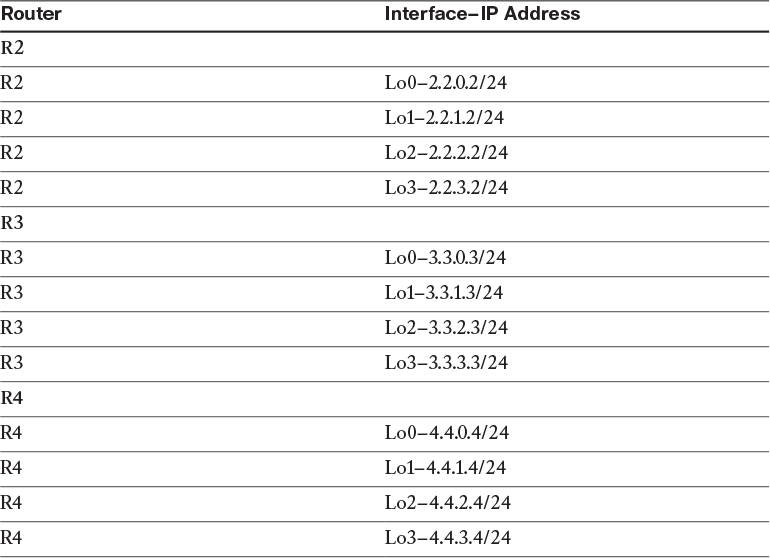
Configure the loopback interfaces shown in Table 7-1 on the spoke routers and advertise them in EIGRP AS 100. This may override the Lo0 interfaces of the spokes.
!On R2:
R2(config)# interface loopback0
R2(config-if)# ip address 2.2.0.2 255.255.255.0
R2(config)# interface loopback1
R2(config-if)# ip address 2.2.1.2 255.255.255.0
R2(config)# interface loopback2
R2(config-if)# ip address 2.2.2.2 255.255.255.0
R2(config)# interface loopback3
R2(config-if)# ip address 2.2.3.2 255.255.255.0
R2(config)# router eigrp 100
R2(config-router)# network 2.2.0.2 0.0.0.0
R2(config-router)# network 2.2.1.2 0.0.0.0
R2(config-router)# network 2.2.2.2 0.0.0.0
R2(config-router)# network 2.2.3.2 0.0.0.0
!On R3:
R3(config)# interface loopback0
R3(config-if)# ip address 3.3.0.3 255.255.255.0
R3(config)# interface loopback1
R3(config-if)# ip address 3.3.1.3 255.255.255.0
R3(config)# interface loopback2
R3(config-if)# ip address 3.3.2.3 255.255.255.0
R3(config)# interface loopback3
R3(config-if)# ip address 3.3.3.3 255.255.255.0
R3(config)# router eigrp 100
R3(config-router)# network 3.3.0.3 0.0.0.0
R3(config-router)# network 3.3.1.3 0.0.0.0
R3(config-router)# network 3.3.2.3 0.0.0.0
!On R4:
R4(config)# interface loopback0
R4(config-if)# ip address 4.4.0.4 255.255.255.0
R4(config)# interface loopback1
R4(config-if)# ip address 4.4.1.4 255.255.255.0
R4(config)# interface loopback2
R4(config-if)# ip address 4.4.4.4 255.255.255.0
R4(config)# interface loopback3
R4(config-if)# ip address 4.4.3.4 255.255.255.0
R4(config)# router eigrp 100
R4(config-router)# network 4.4.0.4 0.0.0.0
R4(config-router)# network 4.4.1.4 0.0.0.0
R4(config-router)# network 4.4.2.4 0.0.0.0
R4(config-router)# network 4.4.3.4 0.0.0.0
Let’s verify the configuration:
!On R2:
R2# show ip route eigrp | begin Gate
Gateway of last resort is 200.1.2.10 to network 0.0.0.0
1.0.0.0/24 is subnetted, 1 subnets
D 1.1.1.0 [90/27008000] via 10.1.1.1, 00:20:03, Tunnel1
3.0.0.0/24 is subnetted, 4 subnets
D 3.3.0.0 [90/28288000] via 10.1.1.3, 00:01:33, Tunnel1
D 3.3.1.0 [90/28288000] via 10.1.1.3, 00:01:29, Tunnel1
D 3.3.2.0 [90/28288000] via 10.1.1.3, 00:01:25, Tunnel1
D 3.3.3.0 [90/28288000] via 10.1.1.3, 00:01:40, Tunnel1
4.0.0.0/24 is subnetted, 4 subnets
D 4.4.0.0 [90/28288000] via 10.1.1.4, 00:00:29, Tunnel1
D 4.4.1.0 [90/28288000] via 10.1.1.4, 00:00:26, Tunnel1
D 4.4.2.0 [90/28288000] via 10.1.1.4, 00:00:22, Tunnel1
D 4.4.3.0 [90/28288000] via 10.1.1.4, 00:00:18, Tunnel1
Task 6
In the future, another 1000 spokes will be added to this DMVPN network. The future spokes will have some networks that they will advertise in this routing domain. In order to cut down on the number of entries in the routing table of the spokes, we decide to summarize existing and future routes on the hub router using the ip summary-address eigrp 100 0.0.0.0 0.0.0.0 command. After summarizing on the hub router, we realize that the communication between the spokes is no longer direct and it traverses the hub router to reach the other spokes. We need to provide a solution through DMVPN so that the communication between the spokes is direct.
Let’s summarize on the hub router based on this task:
!On R1:
R1(config)# interface tunnel1
R1(config-if)# ip summary-address eigrp 100 0.0.0.0 0.0.0.0
Let’s verify the configuration:
!On R2:
R2# show ip route eigrp | begin Gate
Gateway of last resort is 200.1.2.10 to network 0.0.0.0
Why can’t we see the default route injected into the EIGRP routing domain by R1?
The reason we don’t see the default route injected within the EIGRP routing domain is because we have a static default route pointing to the NBMA IP address of the switch to which we are connected. This was done in Task 1. Because static routes have a lower administrative distance, EIGRP’s default route is not injected into the routing table.
Let’s remove the static default route from all routers:
!On All Routers:
Rx(config)# no ip route 0.0.0.0 0.0.0.0
With that accomplished, we can configure specific static routes for the NBMA IP addresses of the other spokes:
!On R1:
R1(config)# ip route 200.1.2.2 255.255.255.255 200.1.1.10
R1(config)# ip route 200.1.3.3 255.255.255.255 200.1.1.10
R1(config)# ip route 200.1.4.4 255.255.255.255 200.1.1.10
!On R2:
R2(config)# ip route 200.1.1.1 255.255.255.255 200.1.2.10
R2(config)# ip route 200.1.3.3 255.255.255.255 200.1.2.10
R2(config)# ip route 200.1.4.4 255.255.255.255 200.1.2.10
!On R3:
R3(config)# ip route 200.1.1.1 255.255.255.255 200.1.3.10
R3(config)# ip route 200.1.2.2 255.255.255.255 200.1.3.10
R3(config)# ip route 200.1.4.4 255.255.255.255 200.1.3.10
!On R4:
R4(config)# ip route 200.1.1.1 255.255.255.255 200.1.4.10
R4(config)# ip route 200.1.2.2 255.255.255.255 200.1.4.10
R4(config)# ip route 200.1.3.3 255.255.255.255 200.1.4.10
We will verify the configuration on R2 to simplify the number of show commands needed to see the impact of this change. Feel free to repeat the verification on the other spoke devices if you like.
Note Once the summarization is configured on the hub router, all spokes point to the hub again, so the main requirement of DMVPN Phase 2 is broken.
R2# show ip route eigrp | begin Gate
Gateway of last resort is 10.1.1.1 to network 0.0.0.0
D* 0.0.0.0/0 [90/27008000] via 10.1.1.1, 00:01:29, Tunnel1
The output of the preceding show command reveals that the next-hop IP address to reach any destination is the hub router (R1) with an IP address of 10.1.1.1.
Let’s test the configuration:
!On R2:
R2# traceroute 3.3.3.3 numeric
Type escape sequence to abort.
Tracing the route to 3.3.3.3
VRF info: (vrf in name/id, vrf out name/id)
1 10.1.1.1 0 msec 4 msec 4 msec
2 10.1.1.3 4 msec * 0 msec
R2# traceroute 3.3.3.3 numeric
Type escape sequence to abort.
Tracing the route to 3.3.3.3
VRF info: (vrf in name/id, vrf out name/id)
1 10.1.1.1 4 msec 4 msec 0 msec
2 10.1.1.3 4 msec * 0 msec
Note The direct spoke-to-spoke communication is no longer available.
What if the DMVPN is converted into Phase 3? The process in Phase 3 is similar to Phase 2 with one major difference. In Phase 3, we have CEF adjacency always resolved because we’re pointing to the hub. So there must be another mechanism used to switch the traffic path to direct spoke-to-spoke tunnels.
The following explains the process:
![]() The data packet is forwarded to the hub router. This is based on Routing Information-Base (RIB) and Forwarding Information-Base.
The data packet is forwarded to the hub router. This is based on Routing Information-Base (RIB) and Forwarding Information-Base.
![]() The hub router gets the data packet from the originating spoke and forwards it to the destination spoke via its tunnel interface. It also realizes that the packet is being forwarded out the same tunnel interface (the hub router knows this because the “incoming” and “outgoing” interfaces have the same ip nhrp network-id configured). The hub router now realizes that it is a transit router for the data packets between the spokes.
The hub router gets the data packet from the originating spoke and forwards it to the destination spoke via its tunnel interface. It also realizes that the packet is being forwarded out the same tunnel interface (the hub router knows this because the “incoming” and “outgoing” interfaces have the same ip nhrp network-id configured). The hub router now realizes that it is a transit router for the data packets between the spokes.
![]() The hub router sends an NHRP Redirect message to the originating spoke router requesting an NHRP Resolution.
The hub router sends an NHRP Redirect message to the originating spoke router requesting an NHRP Resolution.
![]() The originating spoke router gets the NHRP Redirect and triggers an NHRP Resolution request for the destination spoke’s NBMA IP address. The spoke router includes its Tunnel-IP-to-NBMA-IP mapping.
The originating spoke router gets the NHRP Redirect and triggers an NHRP Resolution request for the destination spoke’s NBMA IP address. The spoke router includes its Tunnel-IP-to-NBMA-IP mapping.
![]() The hub router receives the NHRP Resolution request and forwards it to the destination spoke router.
The hub router receives the NHRP Resolution request and forwards it to the destination spoke router.
![]() The destination spoke router receives the NHRP Resolution request and creates an NHRP Resolution reply packet (thanks to the information in the NHRP Resolution request that contains the originating spoke’s Tunnel-IP-to-NBMA-IP mapping).
The destination spoke router receives the NHRP Resolution request and creates an NHRP Resolution reply packet (thanks to the information in the NHRP Resolution request that contains the originating spoke’s Tunnel-IP-to-NBMA-IP mapping).
![]() The destination spoke sends out an NHRP Resolution reply to the originating spoke directly. If IPSec is configured, the destination spoke triggers IPSec to create a direct spoke-to-spoke tunnel before the NHRP Resolution reply is sent.
The destination spoke sends out an NHRP Resolution reply to the originating spoke directly. If IPSec is configured, the destination spoke triggers IPSec to create a direct spoke-to-spoke tunnel before the NHRP Resolution reply is sent.
![]() When the originating spoke receives the NHRP Resolution reply, it adds the destination spoke’s Tunnel-IP-to-NBMA-IP mapping to its NHRP table. It then overrides the previous CEF information for the destination spoke, and then it switches the traffic path to the direct spoke-to-spoke tunnel.
When the originating spoke receives the NHRP Resolution reply, it adds the destination spoke’s Tunnel-IP-to-NBMA-IP mapping to its NHRP table. It then overrides the previous CEF information for the destination spoke, and then it switches the traffic path to the direct spoke-to-spoke tunnel.
We will configure ip nhrp redirect, thus converting our DMVPN to a Phase 3 DMVPN. Here’s how to examine the impact while running EIGRP:
!On R1:
R1(config)# interface tunnel1
R1(config-if)# ip nhrp redirect
Note In Phase 3, we no longer need to instruct the hop router not to change the next-hop IP address.
R1(config-if)# ip next-hop-self eigrp 100
!On R2, R3, and R4:
Rx(config)# interface tunnel1
Rx(config-if)# ip nhrp shortcut
Let’s verify the NHRP table of R1:
!On R1:
R1# show ip nhrp
10.1.1.2/32 via 10.1.1.2
Tunnel1 created 00:00:16, expire 01:59:58
Type: dynamic, Flags: unique registered used
NBMA address: 200.1.2.2
10.1.1.3/32 via 10.1.1.3
Tunnel1 created 00:00:19, expire 01:59:55
Type: dynamic, Flags: unique registered used
NBMA address: 200.1.3.3
10.1.1.4/32 via 10.1.1.4
Tunnel1 created 00:00:16, expire 01:59:58
Type: dynamic, Flags: unique registered used
NBMA address: 200.1.4.4
Let’s test the configuration:
!On R2:
R2# show adjacency tunnel1 detail
Protocol Interface Address
IP Tunnel1 10.1.1.1(11)
0 packets, 0 bytes
epoch 1
sourced in sev-epoch 3
Encap length 24
4500000000000000FF2F28C9C8010202
C801010100000800
Tun endpt
Next chain element:
IP adj out of FastEthernet0/0, addr 200.1.2.10
R2# traceroute 3.3.3.3 numeric
Type escape sequence to abort.
Tracing the route to 3.3.3.3
VRF info: (vrf in name/id, vrf out name/id)
1 10.1.1.1 4 msec 0 msec 4 msec
2 10.1.1.3 4 msec * 0 msec
We can see a single rewrite for the hub router. The “c8010101” is the NBMA IP address of the hub router.
Note “C8” in decimal is 200, followed by 010101 (or 200.1.1.1).
We can also see a rewrite for the spoke router.
R2# show adjacency tunnel1 detail
Protocol Interface Address
IP Tunnel1 10.1.1.1(11)
0 packets, 0 bytes
epoch 1
sourced in sev-epoch 3
Encap length 24
4500000000000000FF2F28C9C8010202
C801010100000800
Tun endpt
Next chain element:
IP adj out of FastEthernet0/0, addr 200.1.2.10
IP Tunnel1 10.1.1.3(8)
0 packets, 0 bytes
epoch 1
sourced in sev-epoch 3
Encap length 24
4500000000000000FF2F26C7C8010202
C801030300000800
Tun endpt
Next chain element:
IP adj out of FastEthernet0/0, addr 200.1.2.10
Now that the second rewrite is in the CEF, the traceroutes should go directly to the destination spoke:
R2# traceroute 3.3.3.3 numeric
Type escape sequence to abort.
Tracing the route to 3.3.3.3
VRF info: (vrf in name/id, vrf out name/id)
1 10.1.1.3 0 msec * 0 msec
This is one major benefit of converting to Phase 3, but how did it happen?
Let’s check the routing and the NHRP table of R2:
R2# show ip route eigrp | begin Gate
Gateway of last resort is 10.1.1.1 to network 0.0.0.0
D* 0.0.0.0/0 [90/27008000] via 10.1.1.1, 00:08:34, Tunnel1
R2# show ip nhrp
3.3.3.0/24 via 10.1.1.3
Tunnel1 created 00:13:04, expire 01:46:55
Type: dynamic, Flags: router
NBMA address: 200.1.3.3
10.1.1.1/32 via 10.1.1.1
Tunnel1 created 01:41:35, never expire
Type: static, Flags: used
NBMA address: 200.1.1.1
10.1.1.2/32 via 10.1.1.2
Tunnel1 created 00:13:04, expire 01:46:55
Type: dynamic, Flags: router unique local
NBMA address: 200.1.2.2
(no-socket)
10.1.1.3/32 via 10.1.1.3
Tunnel1 created 00:13:04, expire 01:46:55
Type: dynamic, Flags: router implicit
NBMA address: 200.1.3.3
The ip nhrp shortcut command instructs the spoke routers to look at their NHRP table and override CEF. This is why the NHRP table can grow. To verify this, let’s ping 4.4.3.4 and look at the NHRP table:
R2# ping 4.4.3.4
Type escape sequence to abort.
Sending 5, 100-byte ICMP Echos to 4.4.4.4, timeout is 2 seconds:
!!!!!
Success rate is 100 percent (5/5), round-trip min/avg/max = 1/3/8 ms
Let’s now verify the NHRP table of R2:
R2# show ip nhrp 4.4.3.0
4.4.3.0/24 via 10.1.1.4
Tunnel1 created 00:01:00, expire 01:58:59
Type: dynamic, Flags: router
NBMA address: 200.1.4.4
Erase the startup configuration of the routers and the switch and reload them before proceeding to the next lab.
Lab 7-2: EIGRP Named Mode

Figure 7-2 EIGRP Named Mode Lab Topology
Task 1
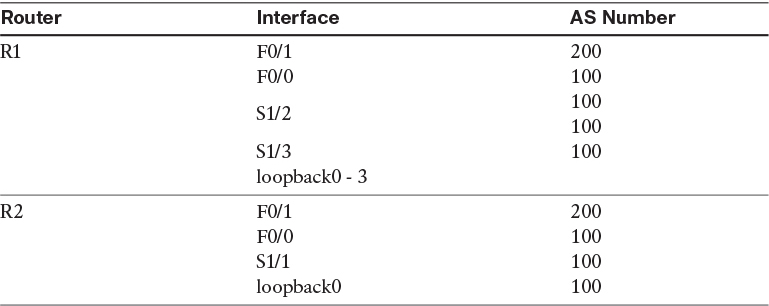
Figure 7-2 illustrates the topology used in the following tasks. Configure EIGRP on R1, R2, and R3 based on the policy shown in Table 7-2.

Here are some key points to keep in mind:
![]() R1 should be configured to use unicast to establish a neighbor adjacency with R2.
R1 should be configured to use unicast to establish a neighbor adjacency with R2.
![]() R1 should use multicast to establish a neighbor adjacency with R3.
R1 should use multicast to establish a neighbor adjacency with R3.
![]() R1, R2, and R3 should use an EIGRP named configuration to accomplish this task.
R1, R2, and R3 should use an EIGRP named configuration to accomplish this task.
Configuring EIGRP with a virtual instance name creates an EIGRP named configuration. If you need to configure another EIGRP instance in another ASN, on the local router you must use another EIGRP virtual instance with a different name and specify the ASN in the address-family command. Between the two routers, the virtual instance name does not need to match; the virtual instance name is locally significant.
The auto-summary is disabled by default. If you enter the no auto-summary command, it will not be displayed in the output of the show run | section router eigrp command, unless it is specifically enabled.
Using the EIGRP named configuration, you configure the network statement under the address-family configuration mode and not directly under the router EIGRP configuration mode. The named configuration supports IPv4, IPv6, and VRF instances using different address-family types in a single EIGRP instance.
The named configuration provides a single place for all EIGRP commands, and it can be displayed using a single show command.
!On R1:
R1(config)# router eigrp AS100
R1(config-router)# address-family ipv4 unicast autonomous-system 100
R1(config-router-af)# network 12.1.1.1 0.0.0.0
R1(config-router-af)# network 13.1.1.1 0.0.0.0
R1(config-router-af)# network 145.1.1.1 0.0.0.0
R1(config-router-af)# network 1.1.0.1 0.0.0.0
R1(config-router-af)# network 1.1.1.1 0.0.0.0
R1(config-router-af)# network 1.1.2.1 0.0.0.0
R1(config-router-af)# network 1.1.3.1 0.0.0.0
You can see that the neighbor command is configured under the address-family and not directly under the router eigrp configuration mode:
R1(config-router-af)# neighbor 12.1.1.2 serial1/2
Note R1 could have been configured using the network 0.0.0.0 statement instead of seven network statements. With the network 0.0.0.0 statement, you are running EIGRP on all existing and future interface(s) in the specified AS. Some engineers configure EIGRP using the following method:
network 12.1.1.0 0.0.0.255
network 13.1.1.0 0.0.0.255
In the preceding example, you are running EIGRP AS 100 on all interfaces in networks 12.1.1.0/24 and 13.1.1.0/24. This means that if these networks use variable-length subnet masking (VLSM), then EIGRP AS 100 is running on all subsets of these two networks. The best way to configure EIGRP is to be very specific, like the configuration performed on R1. Let’s continue with our configuration:
Note You can use as instead of autonomous-system.
R1(config)# router eigrp AS200
R1(config-router)# address-family ipv4 unicast as 200
R1(config-router-af)# network 10.1.1.1 0.0.0.0
Tip In order to minimize the amount of typing you have to do when configuring EIGRP named mode, once one end is configured, you should issue a show run | section router eigrp command.
R1# show run | section router eigrp AS100
router eigrp AS100
!
address-family ipv4 unicast autonomous-system 100
!
topology base
exit-af-topology
neighbor 12.1.1.2 Serial1/2
network 1.1.0.1 0.0.0.0
network 1.1.1.1 0.0.0.0
network 1.1.2.1 0.0.0.0
network 1.1.3.1 0.0.0.0
network 12.1.1.1 0.0.0.0
network 13.1.1.1 0.0.0.0
network 145.1.1.1 0.0.0.0
exit-address-family
Copy the first three lines after the show command and paste them on the other router(s) running in the same AS; then all you have to do is enter the network command:
!On R2:
R2(config)# router eigrp AS100
R2(config-router)# address-family ipv4 unicast autonomous-system 100
R2(config-router-af)# network 12.1.1.2 0.0.0.0
R2(config-router-af)# network 23.1.1.2 0.0.0.0
R2(config-router-af)# network 2.2.2.2 0.0.0.0
In EIGRP, if one neighbor is configured for unicast, the other end has to be configured for unicast as well; you cannot have one end configured for unicast and the other for multicast.
R2(config-router-af)# neighbor 12.1.1.1 serial1/1
You should see the following console message stating that a neighbor adjacency has been established between the local router and R1 (12.1.1.1):
%DUAL-5-NBRCHANGE: EIGRP-IPv4 100: Neighbor 12.1.1.1 (Serial1/1) is up: new adjacency
R2(config)# router eigrp AS200
R2(config-router)# address-family ipv4 unicast as 200
R2(config-router-af)# network 10.1.1.2 0.0.0.0
You should see the following console message stating that the local router has established an adjacency with R1 (10.1.1.1):
%DUAL-5-NBRCHANGE: EIGRP-IPv4 200: Neighbor 10.1.1.1 (FastEthernet0/1) is
up: new adjacency
!On R3:
R3(config)# router eigrp AS100
R3(config-router)# address-family ipv4 unicast as 100
R3(config-router-af)# network 23.1.1.3 0.0.0.0
R3(config-router-af)# network 13.1.1.3 0.0.0.0
R3(config-router-af)# network 3.3.3.3 0.0.0.0
You should see the following console message stating that the local router has established an adjacency with R1 (13.1.1.1) and R2 (23.1.1.2):
%DUAL-5-NBRCHANGE: EIGRP-IPv4 100: Neighbor 23.1.1.2 (FastEthernet0/0) is up: new adjacency
%DUAL-5-NBRCHANGE: EIGRP-IPv4 100: Neighbor 13.1.1.1 (Serial1/1) is up: new adjacency
Let’s verify the configuration:
!On R3:
R3# show ip route eigrp 100 | begin Gate
Gateway of last resort is not set
1.0.0.0/24 is subnetted, 4 subnets
D 1.1.0.0 [90/36195328] via 13.1.1.1, 00:01:29, Serial1/1
D 1.1.1.0 [90/36195328] via 13.1.1.1, 00:01:29, Serial1/1
D 1.1.2.0 [90/36195328] via 13.1.1.1, 00:01:29, Serial1/1
D 1.1.3.0 [90/36195328] via 13.1.1.1, 00:01:29, Serial1/1
D 2.0.0.0/8 [90/156160] via 23.1.1.2, 00:01:31, FastEthernet0/0
12.0.0.0/24 is subnetted, 1 subnets
D 12.1.1.0 [90/40514560] via 23.1.1.2, 00:01:31, FastEthernet0/0
145.1.0.0/24 is subnetted, 1 subnets
D 145.1.1.0 [90/36069888] via 13.1.1.1, 00:01:29, Serial1/1
!On R1:
R1# show ip route eigrp | begin Gate
Gateway of last resort is not set
D 2.0.0.0/8 [90/36197888] via 13.1.1.3, 00:09:23, Serial1/3
D 3.0.0.0/8 [90/36195328] via 13.1.1.3, 00:09:18, Serial1/3
23.0.0.0/24 is subnetted, 1 subnets
D 23.1.1.0 [90/36069888] via 13.1.1.3, 00:09:23, Serial1/3
You can see that EIGRP has the capability to establish unicast or multicast—or in this case, both simultaneously.
Task 2
Configure EIGRP on R4 and R5 in AS 100. You must use named mode to accomplish this task.
!On R4:
R4(config)# router eigrp AS100
R4(config-router)# address-family ipv4 unicast as 100
R4(config-router-af)# network 145.1.1.4 0.0.0.0
R4(config-router-af)# network 4.4.4.4 0.0.0.0
You should see the following console message:
%DUAL-5-NBRCHANGE: EIGRP-IPv4 100: Neighbor 145.1.1.1 (FastEthernet0/0) is up: new adjacency
!On R5:
R5(config)# router eigrp AS100
R5(config-router)# address-family ipv4 unicast as 100
R5(config-router-af)# network 5.5.5.5 0.0.0.0
R5(config-router-af)# network 145.1.1.5 0.0.0.0
You should see the following console messages as well:
%DUAL-5-NBRCHANGE: EIGRP-IPv4 100: Neighbor 145.1.1.4 (FastEthernet0/0) is up: new adjacency
%DUAL-5-NBRCHANGE: EIGRP-IPv4 100: Neighbor 145.1.1.1 (FastEthernet0/0) is up: new adjacency
Let’s verify the configuration:
!On R5:
R5# show ip route eigrp | begin Gate
Gateway of last resort is not set
1.0.0.0/24 is subnetted, 4 subnets
D 1.1.0.0 [90/156160] via 145.1.1.1, 00:01:04, FastEthernet0/0
D 1.1.1.0 [90/156160] via 145.1.1.1, 00:01:04, FastEthernet0/0
D 1.1.2.0 [90/156160] via 145.1.1.1, 00:01:04, FastEthernet0/0
D 1.1.3.0 [90/156160] via 145.1.1.1, 00:01:04, FastEthernet0/0
D 2.0.0.0/8 [90/36200448] via 145.1.1.1, 00:01:04, FastEthernet0/0
D 3.0.0.0/8 [90/36197888] via 145.1.1.1, 00:01:04, FastEthernet0/0
D 4.0.0.0/8 [90/156160] via 145.1.1.4, 00:01:04, FastEthernet0/0
12.0.0.0/24 is subnetted, 1 subnets
D 12.1.1.0 [90/40514560] via 145.1.1.1, 00:01:04, FastEthernet0/0
13.0.0.0/24 is subnetted, 1 subnets
D 13.1.1.0 [90/36069888] via 145.1.1.1, 00:01:04, FastEthernet0/0
23.0.0.0/24 is subnetted, 1 subnets
D 23.1.1.0 [90/36072448] via 145.1.1.1, 00:01:04, FastEthernet0/0
Task 3
Configure R1, R4, and R5 to use unicast to establish their neighbor adjacency:
!On R1:
R1(config)# router eigrp AS100
R1(config-router)# address-family ipv4 unicast as 100
R1(config-router-af)# neighbor 145.1.1.4 fastEthernet0/0
R1(config-router-af)# neighbor 145.1.1.5 fastEthernet0/0
Once the preceding neighbor commands are configured, you should see the following console messages, which state that both neighbors (R4 and R5) lost their adjacency to the local router:
%DUAL-5-NBRCHANGE: EIGRP-IPv4 100: Neighbor 145.1.1.5 (FastEthernet0/0) is down:
Static peer configured
%DUAL-5-NBRCHANGE: EIGRP-IPv4 100: Neighbor 145.1.1.4 (FastEthernet0/0) is down:
Static peer configured
But why didn’t R5 reestablish its adjacency?
In Task 1, you saw that EIGRP established a unicast adjacency with R2 and a multicast adjacency with R3. But in this case, once the neighbor command was configured, all adjacencies on that segment were torn down. So what is different about R1, R4, and R5 versus R1, R2, and R3?
R1, R2, and R3 were configured in a point-to-point manner, whereas R1, R4 and R5 are on the same Ethernet segment. On a broadcast network, EIGRP cannot unicast to one or more neighbors and multicast to others. It’s either one or the other.
Let’s configure R4 and R5:
!On R4:
R4(config)# router eigrp AS100
R4(config-router)# address-family ipv4 unicast as 100
R4(config-router-af)# neighbor 145.1.1.1 fastEthernet0/0
R4(config-router-af)# neighbor 145.1.1.5 fastEthernet0/0
You should see the following console message:
%DUAL-5-NBRCHANGE: EIGRP-IPv4 100: Neighbor 145.1.1.1 (FastEthernet0/0) is up: new adjacency
!On R5:
R5(config)# router eigrp AS100
R5(config-router)# address-family ipv4 unicast as 100
R5(config-router-af)# neighbor 145.1.1.1 fastethernet0/0
R5(config-router-af)# neighbor 145.1.1.4 fastethernet0/0
You should also see the following console messages:
%DUAL-5-NBRCHANGE: EIGRP-IPv4 100: Neighbor 145.1.1.1 (FastEthernet0/0) is up: new adjacency
%DUAL-5-NBRCHANGE: EIGRP-IPv4 100: Neighbor 145.1.1.4 (FastEthernet0/0) is up: new adjacency
Let’s verify the configuration:
!On R4:
R4# show ip route eigrp | begin Gate
Gateway of last resort is not set
1.0.0.0/24 is subnetted, 4 subnets
D 1.1.0.0 [90/156160] via 145.1.1.1, 00:07:46, FastEthernet0/0
D 1.1.1.0 [90/156160] via 145.1.1.1, 00:07:46, FastEthernet0/0
D 1.1.2.0 [90/156160] via 145.1.1.1, 00:07:46, FastEthernet0/0
D 1.1.3.0 [90/156160] via 145.1.1.1, 00:07:46, FastEthernet0/0
D 2.0.0.0/8 [90/36200448] via 145.1.1.1, 00:07:46, FastEthernet0/0
D 3.0.0.0/8 [90/36197888] via 145.1.1.1, 00:07:46, FastEthernet0/0
D 5.0.0.0/8 [90/156160] via 145.1.1.5, 00:00:17, FastEthernet0/0
12.0.0.0/24 is subnetted, 1 subnets
D 12.1.1.0 [90/40514560] via 145.1.1.1, 00:07:46, FastEthernet0/0
13.0.0.0/24 is subnetted, 1 subnets
D 13.1.1.0 [90/36069888] via 145.1.1.1, 00:07:46, FastEthernet0/0
23.0.0.0/24 is subnetted, 1 subnets
D 23.1.1.0 [90/36072448] via 145.1.1.1, 00:07:46, FastEthernet0/0
Task 4
Configure R6 in EIGRP AS 200. This router should run EIGRP AS 200 on its F0/1 and loopback0 interfaces. You should use an EIGRP named mode to accomplish this task.
!On R6:
R6(config)# router eigrp AS200
R6(config-router)# address-family ipv4 unicast as 200
R6(config-router-af)# network 6.6.6.6 0.0.0.0
R6(config-router-af)# network 10.1.1.6 0.0.0.0
You should see the following console messages:
%DUAL-5-NBRCHANGE: EIGRP-IPv4 200: Neighbor 10.1.1.2 (FastEthernet0/1) is up: new adjacency
%DUAL-5-NBRCHANGE: EIGRP-IPv4 200: Neighbor 10.1.1.1 (FastEthernet0/1) is up: new adjacency
Let’s verify the configuration:
!On R1:
R1# show ip route eigrp 200 | begin Gate
Gateway of last resort is not set
D 6.0.0.0/8 [90/156160] via 10.1.1.6, 00:03:03, FastEthernet0/1
Task 5
Configure OSPF area 0 on the F0/1 interfaces of R6 and R7 and on the loopback0 interface of R7. You should use a router ID of your choice. Change the OSPF network type of R7’s loopback0 interface to point-to-point.
Note The Open Shortest Path First (OSPF) protocol will be covered in later labs.
!On R6:
R6(config)# router ospf 1
R6(config-router)# router-id 0.0.0.6
R6(config-router)# network 10.1.1.6 0.0.0.0 area 0
!On R7:
R7(config)# interface loopback0
R7(config-if)# ip ospf network point-to-point
R7(config)# router ospf 1
R7(config-router)# router-id 0.0.0.7
R7(config-router)# network 10.1.1.7 0.0.0.0 area 0
R7(config-router)# network 7.7.7.7 0.0.0.0 area 0
You should see the following console message:
%OSPF-5-ADJCHG: Process 1, Nbr 0.0.0.6 on GigabitEthernet0/1 from LOADING to FULL, Loading Done
Let’s verify the configuration:
!On R6:
R6# show ip route ospf | begin Gate
Gateway of last resort is not set
O 7.0.0.0/8 [110/2] via 10.1.1.7, 00:00:25, FastEthernet0/1
Task 6
Configure R6 to redistribute OSPF into EIGRP such that R1 and R2 go directly to R7 to reach network 7.0.0.0/8 (R7’s Lo0).
In the address-family configuration mode, you will see the “topology base.” The route redistribution is configured in this subconfiguration mode. The following commands are configured in this mode:
R6(config)# router eigrp AS200
R6(config-router)# address-family ipv4 unicast as 200
R6(config-router-af)# topology base
R6(config-router-af-topology)#?
Address Family Topology configuration commands:
auto-summary Enable automatic network number summarization
default Set a command to its defaults
default-information Control distribution of default information
default-metric Set metric of redistributed routes
distance Define an administrative distance
distribute-list Filter entries in eigrp updates
eigrp EIGRP specific commands
exit-af-topology Exit from Address Family Topology configuration mode
maximum-paths Forward packets over multiple paths
metric Modify metrics and parameters for advertisement
no Negate a command or set its defaults
offset-list Add or subtract offset from EIGRP metrics
redistribute Redistribute IPv4 routes from another routing protocol
snmp Modify snmp parameters
summary-metric Specify summary to apply metric/filtering
timers Adjust topology specific timers
traffic-share How to compute traffic share over alternate paths
variance Control load balancing variance
Note Redistribution is covered in detail in Chapter 9, “Redistribution.”
!On R6
R6(config)# router eigrp AS200
R6(config-router)# address-family ipv4 unicast as 200
R6(config-router-af)# topology base
R6(config-router-af-topology)# redistribute ospf 1 metric 1 1 1 1 1
Let’s verify the configuration:
!On R1:
R1# show ip route 7.7.7.7
Routing entry for 7.0.0.0/8
Known via "eigrp 200", distance 170, metric 2560002816, type external
Redistributing via eigrp 200
Last update from 10.1.1.6 on FastEthernet0/1, 00:11:13 ago
Routing Descriptor Blocks:
* 10.1.1.6, from 10.1.1.6, 00:11:13 ago, via FastEthernet0/1
Route metric is 2560002816, traffic share count is 1
Total delay is 110 microseconds, minimum bandwidth is 1 Kbit
Reliability 1/255, minimum MTU 1 bytes
Loading 1/255, Hops 1
R1# traceroute 7.7.7.7 numeric
Type escape sequence to abort.
Tracing the route to 7.7.7.7
VRF info: (vrf in name/id, vrf out name/id)
1 10.1.1.6 4 msec 0 msec 4 msec
2 10.1.1.7 0 msec * 0 msec
You can see that the next hop is pointing to R6 and not R7. To resolve this task, we can use the third-party next hop; in classic EIGRP configuration, this feature was configured directly under the interface, but in the EIGRP named mode, it’s configured in the af-interface mode directly under the address-family configuration mode. Let’s look at our options in the af-interface mode:
!On R6:
R6(config)# router eigrp AS200
R6(config-router)# address-family ipv4 unicast as 200
R6(config-router-af)# af-interface fastEthernet0/1
R6(config-router-af-interface)#?
Address Family Interfaces configuration commands:
authentication authentication subcommands
bandwidth-percent Set percentage of bandwidth percentage limit
bfd Enable Bidirectional Forwarding Detection
dampening-change Percent interface metric must change to cause update
dampening-interval Time in seconds to check interface metrics
default Set a command to its defaults
exit-af-interface Exit from Address Family Interface configuration mode
hello-interval Configures hello interval
hold-time Configures hold time
next-hop-self Configures EIGRP next-hop-self
no Negate a command or set its defaults
passive-interface Suppress address updates on an interface
shutdown Disable Address-Family on interface
split-horizon Perform split horizon
summary-address Perform address summarization
You can see that most if not all the interface-configuration commands for EIGRP are listed in this mode. Let’s configure the third-party next hop:
R6(config-router-af-interface)# no next-hop-self
Now let’s verify the configuration:
!On R1:
R1# show ip route 7.7.7.7
Routing entry for 7.0.0.0/8
Known via "eigrp 200", distance 170, metric 2560002816, type external
Redistributing via eigrp 200
Last update from 10.1.1.7 on FastEthernet0/1, 00:01:09 ago
Routing Descriptor Blocks:
* 10.1.1.7, from 10.1.1.6, 00:01:09 ago, via FastEthernet0/1
Route metric is 2560002816, traffic share count is 1
Total delay is 110 microseconds, minimum bandwidth is 1 Kbit
Reliability 1/255, minimum MTU 1 bytes
Loading 1/255, Hops 1
R1# traceroute 7.7.7.7 numeric
Type escape sequence to abort.
Tracing the route to 7.7.7.7
VRF info: (vrf in name/id, vrf out name/id)
1 10.1.1.7 0 msec * 0 msec
Task 7
Configure the hello interval of all routers in AS 200 to be twice as much as the default.
To start, let’s look at the default value for the hello interval on R1:
R1# show ip eigrp 200 interface detail
EIGRP-IPv4 VR(tst200) Address-Family Interfaces for AS(200)
Xmit Queue Mean Pacing Time Multicast Pending
Interface Peers Un/Reliable SRTT Un/Reliable Flow Timer Routes
Fa0/1 2 0/0 6 0/1 50 0
Hello-interval is 5, Hold-time is 15
Split-horizon is enabled
Next xmit serial <none>
Un/reliable mcasts: 0/4 Un/reliable ucasts: 6/8
Mcast exceptions: 0 CR packets: 0 ACKs suppressed: 0
Retransmissions sent: 3 Out-of-sequence rcvd: 0
Topology-ids on interface - 0
Authentication mode is not set
Now that we know the default values, let’s change the hello interval to 10 seconds:
!On R1, R2, and R6:
Rx(config)# router eigrp AS200
Rx(config-router)# address-family ipv4 unicast as 200
Rx(config-router-af)# af-interface fastEthernet0/1
Rx(config-router-af-interface)# hello-interval 10
Now let’s verify the configuration:
!On R1:
R1# show ip eigrp 200 interface detail
EIGRP-IPv4 VR(tst200) Address-Family Interfaces for AS(200)
Xmit Queue Mean Pacing Time Multicast Pending
Interface Peers Un/Reliable SRTT Un/Reliable Flow Timer Routes
Fa0/1 2 0/0 6 0/1 50 0
Hello-interval is 10, Hold-time is 15
Split-horizon is enabled
Next xmit serial <none>
Un/reliable mcasts: 0/4 Un/reliable ucasts: 6/8
Mcast exceptions: 0 CR packets: 0 ACKs suppressed: 0
Retransmissions sent: 3 Out-of-sequence rcvd: 0
Topology-ids on interface - 0
Authentication mode is not set
Note When the hello interval is changed, the hold time is not changed automatically.
Task 8
R4 should be configured such that in the worst-case scenario, it uses 10% of the bandwidth for its EIGRP updates. This policy should apply to the existing and future interfaces.
By default, EIGRP will only consume 50% of its interface’s bandwidth; this can be changed using the bandwidth-percent command in interface-configuration mode or in the af-interface configuration mode under the address-family. Let’s configure this feature in the af-interface configuration mode:
!On R4:
R4(config)# router eigrp AS100
R4(config-router)# address-family ipv4 unicast as 100
When af-interface default is used, instead of referencing a given interface, the configuration is applied to all existing and future interfaces on this router:
R4(config-router-af)# af-interface default
R4(config-router-af-interface)# bandwidth-percent 10
Let’s verify the configuration:
!On R4:
R4# show ip eigrp 100 interface detail
EIGRP-IPv4 VR(AS100) Address-Family Interfaces for AS(100)
Xmit Queue PeerQ Mean Pacing Time Multicast Pending
Interface Peers Un/Reliable Un/Reliable SRTT Un/Reliable Flow Timer Routes
Fa0/0 2 0/0 0/0 5 0/1 50 0
Hello-interval is 5, Hold-time is 15
Split-horizon is enabled
Next xmit serial <none>
Packetized sent/expedited: 28/1
Hello's sent/expedited: 16855/5
Un/reliable mcasts: 0/9 Un/reliable ucasts: 41/19
Mcast exceptions: 0 CR packets: 0 ACKs suppressed: 1
Retransmissions sent: 2 Out-of-sequence rcvd: 1
Topology-ids on interface - 0
Interface BW percentage is 10
Authentication mode is not set
Lo0 0 0/0 0/0 0 0/0 0 0
Hello-interval is 5, Hold-time is 15
Split-horizon is enabled
Next xmit serial <none>
Packetized sent/expedited: 0/0
Hello's sent/expedited: 0/1
Un/reliable mcasts: 0/0 Un/reliable ucasts: 0/0
Mcast exceptions: 0 CR packets: 0 ACKs suppressed: 0
Retransmissions sent: 0 Out-of-sequence rcvd: 0
Topology-ids on interface - 0
Interface BW percentage is 10
Authentication mode is not set
Task 9
Configure R1 to summarize its loopback interfaces and advertise a single summary.
Note The af-interface default command cannot be used for summarization. The interface(s) must be specified, like so:
!On R1:
R1(config)# router eigrp AS100
R1(config-router)# address-family ipv4 unicast as 100
R1(config-router-af)# af-interface serial1/2
R1(config-router-af-interface)# summary-address 1.1.0.0 255.255.252.0
R1(config-router-af)# af-interface serial1/3
R1(config-router-af-interface)# summary-address 1.1.0.0 255.255.252.0
Let’s verify the configuration:
!On R2:
R2# show ip route eigrp | begin Gate
Gateway of last resort is not set
1.0.0.0/22 is subnetted, 1 subnets
D 1.1.0.0 [90/36197888] via 23.1.1.3, 00:02:24, FastEthernet0/0
D 3.0.0.0/8 [90/156160] via 23.1.1.3, 02:19:11, FastEthernet0/0
D 4.0.0.0/8 [90/36200448] via 23.1.1.3, 01:47:13, FastEthernet0/0
D 5.0.0.0/8 [90/36200448] via 23.1.1.3, 01:46:18, FastEthernet0/0
D 6.0.0.0/8 [90/156160] via 10.1.1.6, 00:46:08, FastEthernet0/1
7.0.0.0/32 is subnetted, 1 subnets
D EX 7.7.7.7 [170/2560002816] via 10.1.1.7, 00:46:08, FastEthernet0/1
13.0.0.0/24 is subnetted, 1 subnets
D 13.1.1.0 [90/36069888] via 23.1.1.3, 02:19:17, FastEthernet0/0
145.1.0.0/24 is subnetted, 1 subnets
D 145.1.1.0 [90/36072448] via 23.1.1.3, 02:04:01, FastEthernet0/0
!On R3:
R3# show ip route eigrp | begin Gate
Gateway of last resort is not set
1.0.0.0/22 is subnetted, 1 subnets
D 1.1.0.0 [90/36195328] via 13.1.1.1, 00:03:23, Serial1/1
D 2.0.0.0/8 [90/156160] via 23.1.1.2, 02:20:14, FastEthernet0/0
D 4.0.0.0/8 [90/36197888] via 13.1.1.1, 01:48:13, Serial1/1
D 5.0.0.0/8 [90/36197888] via 13.1.1.1, 01:47:18, Serial1/1
12.0.0.0/24 is subnetted, 1 subnets
D 12.1.1.0 [90/40514560] via 23.1.1.2, 02:20:14, FastEthernet0/0
145.1.0.0/24 is subnetted, 1 subnets
D 145.1.1.0 [90/36069888] via 13.1.1.1, 02:05:01, Serial1/1
You can see that R2 traverses through R3 to get to the loopback interfaces or to the summary for the loopback interfaces, whereas R3 goes directly to R1 to reach the summary route. This is because the bandwidth of R2’s link to R1 is set to 64 Kbps, whereas the bandwidth of R3’s link to R1 is set to 72 Kbps. Here’s how to test this:
!On R2:
R2# traceroute 1.1.1.1 numeric
Type escape sequence to abort.
Tracing the route to 1.1.1.1
VRF info: (vrf in name/id, vrf out name/id)
1 23.1.1.3 0 msec 0 msec 0 msec
2 13.1.1.1 16 msec * 12 msec
!On R3:
R3# traceroute 1.1.1.1 numeric
Type escape sequence to abort.
Tracing the route to 1.1.1.1
VRF info: (vrf in name/id, vrf out name/id)
1 13.1.1.1 12 msec * 12 msec
Task 10
Configure R1 to assign a fixed metric to its summary route such that R2 and R3 both use R1 as the next hop to reach the more specific routes of the summary, regardless of the bandwidth command on the serial links to R2 and R3.
Before we configure this task, let’s look at the cost of the summary route on R2 and R3:
!On R2:
R2# show ip route 1.1.0.0 | include metric
Known via "eigrp 100", distance 90, metric 36197888, type internal
Route metric is 36197888, traffic share count is 1
!On R3:
R3# show ip route 1.1.0.0 | include metric
Known via "eigrp 100", distance 90, metric 36195328, type internal
Route metric is 36195328, traffic share count is 1
The traceroutes performed at the end of the previous task revealed that R2 goes through R3 to reach the more specific routes of the summary. Let’s assign a fixed cost to the summary so that both R2 and R3 use R1 as the next hop to reach the components of the summary route:
!On R1:
R1(config)# router eigrp AS100
R1(config-router)# address-family ipv4 unicast as 100
R1(config-router-af)# topology base
R1(config-router-af-topology)# summary-metric 1.1.0.0/22 1 1 1 1 1
The preceding command assigns a fixed metric for the EIGRP summary route. You can use the metric of the actual interface instead of 1 1 1 1 1.
Let’s verify the configuration:
!On R2:
R2# show ip route 1.1.0.0 | include metric
Known via "eigrp 100", distance 90, metric 2560512256, type internal
Route metric is 2560512256, traffic share count is 1
!On R3:
R3# show ip route 1.1.0.0 | include metric
Known via "eigrp 100", distance 90, metric 2560512256, type internal
Route metric is 2560512256, traffic share count is 1
Now let’s test the configuration:
!On R2:
R2# traceroute 1.1.1.1 numeric
Type escape sequence to abort.
Tracing the route to 1.1.1.1
VRF info: (vrf in name/id, vrf out name/id)
1 12.1.1.1 12 msec * 12 msec
!On R3:
R3# traceroute 1.1.1.1 numeric
Type escape sequence to abort.
Tracing the route to 1.1.1.1
VRF info: (vrf in name/id, vrf out name/id)
1 13.1.1.1 16 msec * 12 msec
Task 11
Configure R1 to limit the number of received prefixes from R5 to 10. R1 should be configured to receive a warning message once 50% of this threshold is reached and a warning message for every additional route that exceeds the threshold.
To test this feature, let’s configure 10 additional loopback interfaces on R5 and then advertise one at a time and verify the result:
!On R5:
R5(config)# interface loopback1
R5(config-if)# ip address 51.1.1.5 255.0.0.0
R5(config-if)# interface loopback2
R5(config-if)# ip address 52.1.1.5 255.0.0.0
R5(config-if)# interface loopback3
R5(config-if)# ip address 53.1.1.5 255.0.0.0
R5(config-if)# interface loopback4
R5(config-if)# ip address 54.1.1.5 255.0.0.0
R5(config-if)# interface loopback5
R5(config-if)# ip address 55.1.1.5 255.0.0.0
R5(config-if)# interface loopback6
R5(config-if)# ip address 56.1.1.5 255.0.0.0
R5(config-if)# interface loopback7
R5(config-if)# ip address 57.1.1.5 255.0.0.0
R5(config-if)# interface loopback8
R5(config-if)# ip address 58.1.1.5 255.0.0.0
R5(config-if)# interface loopback9
R5(config-if)# ip address 59.1.1.5 255.0.0.0
R5(config-if)# interface loopback10
R5(config-if)# ip address 60.1.1.5 255.0.0.0
Let’s configure R1 for this feature:
!On R1:
R1(config)# router eigrp AS100
R1(config-router)# address-family ipv4 unicast as 100
R1(config-router-af)# neighbor 145.1.1.5 maximum-prefix 10 50 warning-only
Now let’s test and verify the configuration:
!On R5:
R5(config)# router eigrp AS100
R5(config-router)# address-family ipv4 unicast as 100
R5(config-router-af)# network 51.1.1.5 0.0.0.0
R5(config-router-af)# network 52.1.1.5 0.0.0.0
R5(config-router-af)# network 53.1.1.5 0.0.0.0
R1# show ip route eigrp | include 145.1.1.5
D 5.0.0.0/8 [90/156160] via 145.1.1.5, 00:19:51, FastEthernet0/0
D 51.0.0.0/8 [90/156160] via 145.1.1.5, 00:01:03, FastEthernet0/0
D 52.1.1.0 [90/156160] via 145.1.1.5, 00:00:57, FastEthernet0/0
D 53.1.1.0 [90/156160] via 145.1.1.5, 00:00:51, FastEthernet0/0
So far, R1 has not received any warning messages because it is only receiving four networks from R5 (R5’s Lo0, Lo1, Lo2, and Lo3). Let’s advertise one more and verify the result:
R5(config-router-af)# network 54.1.1.5 0.0.0.0
Now let’s check the console messages on R1. Here’s the first message received:
!On R1:
%DUAL-4-PFXLIMITTHR: EIGRP-IPv4 100: Neighbor threshold prefix level(5) reached.
Let’s advertise another network on R5 and verify the result:
!On R5:
R5(config-router-af)# network 55.1.1.5 0.0.0.0
No console messages on R1 yet, so let’s advertise another network on R5:
R5(config-router-af)# network 56.1.1.5 0.0.0.0
Still no console messages on R1, so let’s advertise another three networks on R5 to reach the threshold of 10 networks:
R5(config-router-af)# network 57.1.1.5 0.0.0.0
R5(config-router-af)# network 58.1.1.5 0.0.0.0
R5(config-router-af)# network 59.1.1.5 0.0.0.0
Now if we look at R1, we should see the following output:
!On R1:
%DUAL-4-PFXLIMITTHR: EIGRP-IPv4 100: Neighbor threshold prefix level(5) reached.
%DUAL-3-PFXLIMIT: EIGRP-IPv4 100: Neighbor prefix limit reached(10).
Let’s advertise another network on R5 and verify the result:
!On R5:
R5(config-router-af)# network 60.1.1.5 0.0.0.0
You can see that for every additional network above the set threshold, a console message is generated on R1’s console:
!On R1
%DUAL-3-PFXLIMIT: EIGRP-IPv4 100: Neighbor prefix limit reached(10).
Task 12
Configure R1 to limit the number of prefixes received from R4 to five; R1 should be configured to tear down the adjacency if R4 exceeds the specified threshold.
Let’s configure five more loopback interfaces on R4 so we can test this feature:
!On R4:
R4(config)# interface loopback1
R4(config-if)# ip address 41.1.1.4 255.0.0.0
R4(config)# interface loopback2
R4(config-if)# ip address 42.1.1.4 255.0.0.0
R4(config)# interface loopback3
R4(config-if)# ip address 43.1.1.4 255.0.0.0
R4(config)# interface loopback4
R4(config-if)# ip address 44.1.1.4 255.0.0.0
R4(config)# interface loopback5
R4(config-if)# ip address 45.1.1.4 255.0.0.0
Let’s configure R1 for this feature:
!On R1:
R1(config)# router eigrp AS100
R1(config-router)# address-family ipv4 unicast as 100
R1(config-router-af)# neighbor 145.1.1.4 maximum-prefix 5
Let’s go back to R1 and advertise an extra network and verify the results:
!On R4:
R4(config)# router eigrp AS100
R4(config-router)# address-family ipv4 unicast as 100
R4(config-router-af)# network 41.1.1.4 0.0.0.0
So far R1 has not received any console messages because it is only receiving two networks from R4, so let’s advertise three more and verify the result:
R4(config-router-af)# network 42.1.1.4 0.0.0.0
R4(config-router-af)# network 43.1.1.4 0.0.0.0
Sure enough, the following console message is shown on R1 because 80% of the configured threshold was reached:
%DUAL-4-PFXLIMITTHR: EIGRP-IPv4 100: Neighbor threshold prefix level(3) reached.
Let’s advertise one more and verify the console messages on R1:
R4(config-router-af)# network 44.1.1.4 0.0.0.0
You should see the following two console messages on R1 stating that the maximum threshold has been reached:
!On R1:
%DUAL-3-PFXLIMIT: EIGRP-IPv4 100: Neighbor prefix limit reached(5).
%DUAL-5-NBRCHANGE: EIGRP-IPv4 100: Neighbor 145.1.1.4 (FastEthernet0/0) is down:
prefix-limit exceeded
You can see that the neighbor adjacency is torn down, so let’s verify the neighbor table of R4:
R4# show ip eigrp neighbor
EIGRP-IPv4 VR(tst) Address-Family Neighbors for AS(100)
H Address Interface Hold Uptime SRTT RTO Q Seq
(sec) (ms) Cnt Num
1 145.1.1.5 Fa0/0 12 00:14:24 1 200 0 23
R4# show ip route eigrp | begin Gate
Gateway of last resort is not set
D 5.0.0.0/8 [90/156160] via 145.1.1.5, 00:13:57, FastEthernet0/0
D 51.0.0.0/8 [90/156160] via 145.1.1.5, 00:13:57, FastEthernet0/0
D 52.0.0.0/8 [90/156160] via 145.1.1.5, 00:13:57, FastEthernet0/0
D 53.0.0.0/8 [90/156160] via 145.1.1.5, 00:13:57, FastEthernet0/0
D 54.0.0.0/8 [90/156160] via 145.1.1.5, 00:13:57, FastEthernet0/0
D 55.0.0.0/8 [90/156160] via 145.1.1.5, 00:13:57, FastEthernet0/0
D 56.0.0.0/8 [90/156160] via 145.1.1.5, 00:13:57, FastEthernet0/0
D 57.0.0.0/8 [90/156160] via 145.1.1.5, 00:13:57, FastEthernet0/0
D 58.0.0.0/8 [90/156160] via 145.1.1.5, 00:13:57, FastEthernet0/0
D 59.0.0.0/8 [90/156160] via 145.1.1.5, 00:13:57, FastEthernet0/0
D 60.0.0.0/8 [90/156160] via 145.1.1.5, 00:13:57, FastEthernet0/0
You can now see that R4 only exchanges routes with R5 and not R1.
Erase the startup config and reload the routers before proceeding to the next lab.
Lab 7-3: EIGRP Metrics (Classic and Wide)
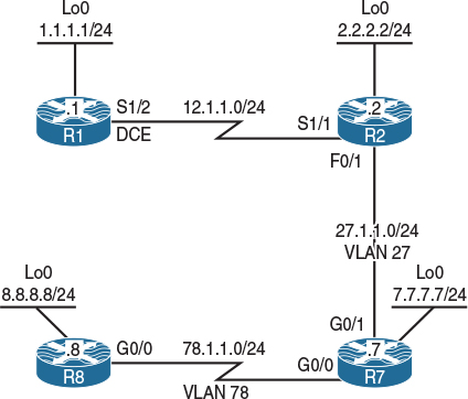
Figure 7-3 EIGRP Metrics Topology
Task 1
Figure 7-3 illustrates the topology used in the following tasks. Configure RIPv2 on R1 and R2. R1 should advertise all of its directly connected interfaces in the RIPv2 routing domain. R2 should be configured to advertise its S1/1 interface in RIPv2. Disable auto summary in RIPv2.
Configure EIGRP AS 100 on the F0/1 and Lo0 interfaces of R2 as well as all interfaces of R7 and R8:
!On R1:
R1(config)# router rip
R1(config-router)# no auto-summary
R1(config-router)# version 2
R1(config-router)# network 1.0.0.0
R1(config-router)# network 12.0.0.0
!On R2
R2(config-subif)# router rip
R2(config-router)# no auto-summary
R2(config-router)# version 2
R2(config-router)# network 12.0.0.0
Let’s verify the configuration:
!On R2:
R2# show ip route rip | begin Gate
Gateway of last resort is not set
1.0.0.0/24 is subnetted, 1 subnets
R 1.1.1.0 [120/1] via 12.1.1.1, 00:00:11, Serial1/1
R2(config-router)# router eigrp 100
R2(config-router)# network 2.2.2.2 0.0.0.0
R2(config-router)# network 27.1.1.2 0.0.0.0
!On R7:
R7(config)# router eigrp 100
R7(config-router)# network 27.1.1.7 0.0.0.0
R7(config-router)# network 7.7.7.7 0.0.0.0
R7(config-router)# network 78.1.1.7 0.0.0.0
You should see the following console message:
%DUAL-5-NBRCHANGE: EIGRP-IPv4 100: Neighbor 27.1.1.2 (GigabitEthernet0/1) is up: new adjacency
!On R8:
R8(config)# router eigrp 100
R8(config-router)# network 78.1.1.8 0.0.0.0
R8(config-router)# network 8.8.8.8 0.0.0.0
You should also see the following console message:
%DUAL-5-NBRCHANGE: EIGRP-IPv4 100: Neighbor 78.1.1.7 (GigabitEthernet0/0) is up: new adjacency
Let’s verify the configuration:
!On R7:
R7# show ip route eigrp | begin Gate
Gateway of last resort is not set
2.0.0.0/24 is subnetted, 1 subnets
D 2.2.2.0 [90/156160] via 27.1.1.2, 00:03:40, GigabitEthernet0/1
8.0.0.0/24 is subnetted, 1 subnets
D 8.8.8.0 [90/156160] via 78.1.1.8, 00:01:47, GigabitEthernet0/0
Task 2
Perform a mutual redistribution between RIPv2 and EIGRP such that R1 sees the EIGRP routes with the correct hop count. For example, R1 should see network 2.2.2.0/24 with a hop count of 1, and network 7.7.7.0/24 with a hop count of 2. Future networks should be redistributed with a hop count of 1.
To resolve this task, an access list is configured to identify every network in the EIGRP routing domain; a route map will be configured to reference a given access list and assign a hop count using the set metric command.
Tip Always issue a show access-lists command before configuring an access list; otherwise, you may add the new access list to an existing one.
!On R2
R2# show access-lists
R2(config)# access-list 2 permit 2.2.2.0 0.0.0.255
R2(config)# access-list 7 permit 7.7.7.0 0.0.0.255
R2(config)# access-list 8 permit 8.8.8.0 0.0.0.255
R2(config)# access-list 27 permit 27.1.1.0 0.0.0.255
R2(config)# access-list 78 permit 78.1.1.0 0.0.0.255
R2(config)# route-map TST permit 10
R2(config-route-map)# match ip address 2
R2(config-route-map)# set metric 1
R2(config)# route-map TST permit 20
R2(config-route-map)# match ip address 7
R2(config-route-map)# set metric 2
R2(config)# route-map TST permit 30
R2(config-route-map)# match ip address 8
R2(config-route-map)# set metric 3
R2(config)# route-map TST permit 40
R2(config-route-map)# match ip address 27
R2(config-route-map)# set metric 1
R2(config)# route-map TST permit 50
R2(config-route-map)# match ip address 78
R2(config-route-map)# set metric 2
R2(config)# route-map TST permit 60
R2(config-route-map)# set metric 1
Note The route-map TST permit 60 command must be configured for the future networks that may be redistributed into RIPv2. These networks will be assigned a hop count of 1, per requirement of this task.
R2(config-router)# router rip
R2(config-router)# redistribute eigrp 100 route-map TST
R2(config)# router eigrp 100
R2(config-router)# redistribute rip metric 1500 20000 255 1 1500
Let’s verify the configuration:
!On R1:
R1# show ip route rip | begin Gate
Gateway of last resort is not set
2.0.0.0/24 is subnetted, 1 subnets
R 2.2.2.0 [120/1] via 12.1.1.2, 00:00:26, Serial1/2
7.0.0.0/24 is subnetted, 1 subnets
R 7.7.7.0 [120/2] via 12.1.1.2, 00:00:26, Serial1/2
8.0.0.0/24 is subnetted, 1 subnets
R 8.8.8.0 [120/3] via 12.1.1.2, 00:00:26, Serial1/2
27.0.0.0/24 is subnetted, 1 subnets
R 27.1.1.0 [120/1] via 12.1.1.2, 00:00:26, Serial1/2
78.0.0.0/24 is subnetted, 1 subnets
R 78.1.1.0 [120/2] via 12.1.1.2, 00:00:26, Serial1/2
Task 3
Explain EIGRP’s composite metric in classic mode configuration. You should explain the formula that EIGRP uses to calculate the composite metric for R2’s loopback0 interface from R7’s perspective.
EIGRP in classic mode uses the following formula:
((K1*BW)+(K2*BW)/(256-load)+(K3*DLY)*(K5/(K4 + Reliability)))*256
The K parameters are multipliers and by default are set to the following:
K1=1, K2=0, K3=1, K4=0, K5=0
The last part of the formula, K5/(K4 + Reliability), only comes into play if the value of K5 is any value except zero. K4 and K5 can be used to allow packet loss and reliability to influence routing decisions. If K5 is equal to zero, the resulting quotient is set to 1. Therefore, by default, the formula that EIGRP uses is
(BW+DLY)*256
Let’s verify the routing table of R7 for the Lo0 interface of R2:
!On R7:
R7# show ip route 2.2.2.2
Routing entry for 2.2.2.0/24
Known via "eigrp 100", distance 90, metric 156160, type internal
Redistributing via eigrp 100
Last update from 27.1.1.2 on GigabitEthernet0/1, 01:05:18 ago
Routing Descriptor Blocks:
* 27.1.1.2, from 27.1.1.2, 01:05:18 ago, via GigabitEthernet0/1
Route metric is 156160, traffic share count is 1
Total delay is 5100 microseconds, minimum bandwidth is 100000 Kbit
Reliability 255/255, minimum MTU 1500 bytes
Loading 1/255, Hops 1
You can see that the cost is 156160.
EIGRP takes the lowest bandwidth (BW) along the path to a given destination. Let’s check the BW of R7’s G0/1 and R2’s Lo0 interfaces:
R7# show interface gigabitEthernet0/1 | include BW
MTU 1500 bytes, BW 100000 Kbit/sec, DLY 100 usec,
R2# show interface loopback0 | include BW
MTU 1514 bytes, BW 8000000 Kbit/sec, DLY 5000 usec,
Therefore, the lowest BW along the path to network 2.2.2.0/24 is 100,000 Kb.
We then divide 10,000,000 Kb (a set value that cannot be changed) by 100,000 Kb, which yields 100.
Now, let’s look at the delay (DLY). EIGRP takes the sum of all DLYs along the path to a given destination. Based on the preceding show commands, you can see that the DLY value of the G0/1 interface of R7 is 100, and the DLY value of the Lo0 interface is 5000. Thus, 5000+100=5100. EIGRP calculates the DLY in tens of microseconds. Therefore, the total DLY value should be divided by 10. Thus, 5100/10=510.
The final step is to add 510 to 100, which is 610, and then multiply that by 256. This gives us a value of 156,160.
Task 4
Reconfigure the EIGRP named mode on the G0/0 interfaces of R7 and R8 as well as the Lo0 interface of R8:
!On R7:
R7(config)# no router eigrp 100
R7(config)# router eigrp tst
R7(config-router)# address-family ipv4 unicast as 100
R7(config-router-af)# network 78.1.1.7 0.0.0.0
!On R8:
R8(config)# no router eigrp 100
R8(config)# router eigrp tst
R8(config-router)# address-family ipv4 unicast as 100
R8(config-router-af)# network 8.8.8.8 0.0.0.0
R8(config-router-af)# network 78.1.1.8 0.0.0.0
You should see the following console message stating that the two routers have established an EIGRP adjacency:
%DUAL-5-NBRCHANGE: EIGRP-IPv4 100: Neighbor 78.1.1.7 (GigabitEthernet0/0) is up: new adjacency
Let’s verify the routing table of R7:
!On R7:
R7# show ip route eigrp | begin Gate
Gateway of last resort is not set
8.0.0.0/24 is subnetted, 1 subnets
D 8.8.8.0 [90/103040] via 78.1.1.8, 00:00:25, GigabitEthernet0/0
Task 5
Explain EIGRP’s composite metric in the named mode configuration. You should explain the formula and the constant values that EIGRP named mode uses to calculate the composite metric for R8’s Lo0 interface.
Let’s display the routing table of R7:
!On R7:
R7# show ip route eigrp | begin Gate
Gateway of last resort is not set
8.0.0.0/24 is subnetted, 1 subnets
D 8.8.8.0 [90/103040] via 78.1.1.8, 00:00:25, GigabitEthernet0/0
You can see that the local router’s cost to get to prefix 8.8.8.0/24 is 103,040. Let’s check the topology table for this prefix:
!On R7:
R7# show ip eigrp topology 8.8.8.0/24
EIGRP-IPv4 VR(tst) Topology Entry for AS(100)/ID(8.8.8.8) for 8.8.8.0/24
State is Passive, Query origin flag is 1, 1 Successor(s), FD is 13189120, RIB is 103040
Descriptor Blocks:
78.1.1.8 (GigabitEthernet0/0), from 78.1.1.8, Send flag is 0x0
Composite metric is (13189120/163840), route is Internal
Vector metric:
Minimum bandwidth is 100000 Kbit
Total delay is 101250000 picoseconds
Reliability is 255/255
Load is 1/255
Minimum MTU is 1500
Hop count is 1
Originating router is 78.1.1.8
The feasible distance is 13,189,120, but the RIB is 103,040. What is going on?
In the EIGRP named mode configuration, we see a metric rib-scale command set to 128 by default. Therefore, if the feasible distance is divided by the rib-scale value, we should see what is entered in the routing table. Let’s verify:
!On R8:
R8# show eigrp protocol
EIGRP-IPv4 VR(tst) Address-Family Protocol for AS(100)
Metric weight K1=1, K2=0, K3=1, K4=0, K5=0 K6=0
Metric rib-scale 128
Metric version 64bit
NSF-aware route hold timer is 240
Router-ID: 8.8.8.8
Topology : 0 (base)
Active Timer: 3 min
Distance: internal 90 external 170
Maximum path: 4
Maximum hopcount 100
Maximum metric variance 1
Total Prefix Count: 2
Total Redist Count: 0
Thus, 13,189,120 / 128 = 103,040. But why did Cisco do that?
The composite metric with EIGRP Wide Metrics is 64 bits. The metric variable in the routing table is a 32-bit value. Larger numbers can’t be installed. Therefore, the rib-scale command can reduce the composite metric so it can fit.
So how does the local router calculate the feasible distance? EIGRP uses a number of defined constants for the calculation of the metric value, and they are based on the following:
EIGRP_BANDWIDTH 10,000,000
EIGRP_DELAY_PICO 1,000,000
Multiplier 65536
Now, that we know the constants, the formula for calculating the composite metric is
Throughput + Latency
But let’s see how these are calculated:
Throughput = EIGRP_BANDWIDTH * 65536 / Min Bandwidth
Here, EIGRP_BANDWIDTH is a constant value and cannot be changed. Also, 65536 is the multiplier and cannot be changed. The Min Bandwidth is taken from the output of the show ip eigrp topology 8.8.8.0/24 command. This means the following:
10,000,000 * 65536 / 100,000 = 6,553,600
Let’s see how the latency is calculated:
Latency = Total delay (In picoseconds) * 65536 / EIGRP_DELAY_PICO
The “total delay in picoseconds” is taken from the output of the show ip eigrp topology 8.8.8.0/24 command. The 65536 is the multiplier and cannot be changed, and EIGRP_DELAY_PICO is a constant value and cannot be changed. This means the following:
101,250,000 * 65536 / 1,000,000 = 6,635,520
The “total delay” is also taken from the output of the show ip EIGRP topology 8.8.8.0/24 command, and EIGRP_DELAY_PICO is the constant value described previously. Now that we have calculated the latency, let’s add the latency to the throughput:
6,553,600 + 6,635,520 = 13,189,120 → The Feasible Distance
Task 6
In the preceding topology, R1 and R2 are Cisco 2811 series routers running c2800nm-adventerprisek9-mz.151-4.M7.bin. R7 and R8 are Cisco 1900 series running c1900-universalk9-mz.SPA.154-1.T.bin. How do we know if these routers support EIGRP Wide Metric?
Here is a way to figure out if the local router has EIGRP Wide Metric support:
!On R8:
R8# show eigrp tech-support | include release
eigrp-release : 14.00.00 : Portable EIGRP Release
On R2:
R2# show eigrp tech-support | include release
eigrp-release : 6.00.00 : Portable EIGRP Release
If the EIGRP release is 8.00.00 or higher, the local router has support for EIGRP Wide Metric. As you can see, R2 does not support it. Another way to see the EIGRP release is to use the following show commands:
!On R8:
R8# show eigrp plugins | include release
eigrp-release : 14.00.00 : Portable EIGRP Release
!On R2:
R2# show eigrp plugins | include release
eigrp-release : 6.00.00 : Portable EIGRP Release
Task 7
Configure the F0/1 interface of R2 and the G0/1 interface to simulate an Ethernet connection. Use bandwidth 10000 and delay 100 to accomplish this. On R2, reconfigure the metric set for RIP routes redistributed into EIGRP to use the lowest possible values. Ensure R8 can ping the Lo0 interface on R1.
EIGRP Wide Metrics can potentially cause problems with slow network connections. In particular, if the metric values are set to 1 1 1 1 1 for prefixes that traverse a slow link, the resulting composite metric will be too large and the FD will be set to Infinity. A prefix with an FD of Infinity will not have a successor and will not be installed into the RIB. This problem can be encountered with older network devices or virtual router environments that have Ethernet interfaces.
Because the computed composite metric is a 64-bit unsigned value, the largest possible value is 18,446,744,073,709,551,615. This value is divided by the rib-scale value. The result is displayed in the EIGRP table as the RIB value. The RIB value is a 32-bit unsigned value. The largest possible RIB value is 4,294,967,295. If the composite metric divided by the rib-scale value is larger than the largest possible RIB value, the RIB value is set to the maximum and the feasible distance (FD) is set to Infinity. An FD of Infinity means the prefix is unreachable, similar to how a RIP prefix that has a hop count of 16 is unreachable. A router will not advertise an unreachable prefix.
Per RFC 7868, with Wide Metrics, a delay value of 0xFFFFFFFFFF (or decimal 281,474,976,719,655) also indicates an unreachable route.
There are two ways to resolve FD being set to Infinity. The first is to use sane values when setting EIGRP metrics. In short, do not use 1 1 1 1 1 when setting metric values. One method is to use bandwidth and delay settings that are normally seen on FastEthernet or GigabitEthernet interfaces. You can use the show interface command to view these values. The second method of avoiding FD being set to Infinity is to increase the rib-scale value.
Before we make any configuration changes, let’s look at the current bandwidth, delay, reliability, and load settings on F0/1 of R2 and G0/1 of R7:
!On R2:
R2# show interface fastethernet0/1 | include BW|load
MTU 1500 bytes, BW 100000 Kbit/sec, DLY 100 usec,
reliability 255/255, txload 1/255, rxload 1/255
!On R7;
R7# show interface gigabitethernet0/1 | include BW|load
MTU 1500 bytes, BW 100000 Kbit/sec, DLY 100 usec,
reliability 255/255, txload 1/255, rxload 1/255
For the first part of the task, set the bandwidth and delay on the interfaces:
!On R2:
R2(config)# interface fastethernet0/1
R2(config-if)# bandwidth 10000
R2(config-if)# delay 100
!On R7:
R7(config)# interface gigabitethernet0/1
R7(config-if)# bandwidth 10000
R7(config-if)# delay 100
!On R2:
R2# show interface fastethernet0/1 | include BW|load
MTU 1500 bytes, BW 10000 Kbit/sec, DLY 1000 usec,
reliability 255/255, txload 1/255, rxload 1/255
!On R7:
R7# show interface gigabitethernet0/1 | include BW|load
MTU 1500 bytes, BW 10000 Kbit/sec, DLY 1000 usec,
reliability 255/255, txload 1/255, rxload 1/255
For the next part of the task, change the metric that is set on the routes redistributed from RIP:
!On R2:
R2(config)# router eigrp 100
R2(config-router)# redistribute rip metric 1 1 1 1 1
Now let’s see what happened on R8:
!On R8:
R8# show ip route eigrp | begin Gate
Gateway of last resort is not set
2.0.0.0/24 is subnetted, 1 subnets
D 2.2.2.0 [90/3635200] via 78.1.1.7, 00:05:41, GigabitEthernet0/0
27.0.0.0/24 is subnetted, 1 subnets
D 27.1.1.0 [90/1075200] via 78.1.1.7, 00:05:41, GigabitEthernet0/0
As you can see, the prefixes from R1 are no longer present. What happened to them?
R8# show ip eigrp topology
EIGRP-IPv4 VR(tst) Topology Table for AS(100)/ID(8.8.8.8)
Codes: P - Passive, A - Active, U - Update, Q - Query, R - Reply,
r - reply Status, s - sia Status
P 2.2.2.0/24, 1 successors, FD is 465305600
via 78.1.1.7 (465305600/458752000), GigabitEthernet0/0
P 27.1.1.0/24, 1 successors, FD is 137625600
via 78.1.1.7 (137625600/131072000), GigabitEthernet0/0
P 78.1.1.0/24, 1 successors, FD is 13107200
via Connected, GigabitEthernet0/0
P 8.8.8.0/24, 1 successors, FD is 163840
via Connected, Loopback0
The prefixes are not present in the EIGRP topology table. Let’s check R7:
!On R7:
R7# show ip route eigrp | begin Gate
Gateway of last resort is not set
2.0.0.0/24 is subnetted, 1 subnets
D 2.2.2.0 [90/3584000] via 27.1.1.2, 00:08:14, GigabitEthernet0/1
8.0.0.0/24 is subnetted, 1 subnets
D 8.8.8.0 [90/103040] via 78.1.1.8, 02:53:09, GigabitEthernet0/0
R7# show ip eigrp topology
EIGRP-IPv4 VR(tst) Topology Table for AS(100)/ID(7.7.7.7)
Codes: P - Passive, A - Active, U - Update, Q - Query, R - Reply,
r - reply Status, s - sia Status
P 2.2.2.0/24, 1 successors, FD is 340787200
via 27.1.1.2 (458752000/327745536), GigabitEthernet0/1
P 27.1.1.0/24, 1 successors, FD is 131072000
via Connected, GigabitEthernet0/1
P 78.1.1.0/24, 1 successors, FD is 13107200
via Connected, GigabitEthernet0/0
P 12.1.1.0/24, 0 successors, FD is Infinity
via 27.1.1.2 (655426191360/655360655360), GigabitEthernet0/1
P 8.8.8.0/24, 1 successors, FD is 13189120
via 78.1.1.8 (13189120/163840), GigabitEthernet0/0
P 1.1.1.0/24, 0 successors, FD is Infinity
via 27.1.1.2 (655426191360/655360655360), GigabitEthernet0/1
The prefixes from R1 have an FD of Infinity and are therefore unreachable. Because the prefixes are unreachable, R7 is not advertising them to R8. You can see that the composite metric value for the prefixes is 655426191360. Take this value and divide by the default rib-scale value of 128, and you get 5,120,517,120. This value is larger than the largest RIB value. This means that the prefix is unreachable. The FD is set to Infinity. If you look at the details of the prefix entry in the EIGRP topology table, you’ll see that the RIB is set to the maximum value, or 4,294,967,295.
Let’s check the details of the EIGRP topology table:
R7# show ip eigrp topology 1.1.1.0/24
EIGRP-IPv4 VR(tst) Topology Entry for AS(100)/ID(7.7.7.7) for 1.1.1.0/24
State is Passive, Query origin flag is 1, 0 Successor(s), FD is Infinity, RIB is 4294967295
Descriptor Blocks:
27.1.1.2 (GigabitEthernet0/1), from 27.1.1.2, Send flag is 0x0
Composite metric is (655426191360/655360655360), route is External
Vector metric:
Minimum bandwidth is 1 Kbit
Total delay is 1010000000 picoseconds
Reliability is 1/255
Load is 1/255
Minimum MTU is 1
Hop count is 1
External data:
Originating router is 2.2.2.2
AS number of route is 0
External protocol is RIP, external metric is 1
Administrator tag is 0 (0x00000000)
R7# show ip eigrp topology zero-successors
EIGRP-IPv4 VR(tst) Topology Table for AS(100)/ID(7.7.7.7)
Codes: P - Passive, A - Active, U - Update, Q - Query, R - Reply,
r - reply Status, s - sia Status
P 12.1.1.0/24, 0 successors, FD is Infinity
via 27.1.1.2 (655426191360/655360655360), GigabitEthernet0/1
P 1.1.1.0/24, 0 successors, FD is Infinity
via 27.1.1.2 (655426191360/655360655360), GigabitEthernet0/1
Because the task asked you to set the metric to the lowest possible value, we’ll have to change the rib-scale value to resolve this problem:
R7(config)# router eigrp tst
R7(config-router)# address-family ipv4 unicast as 100
R7(config-router-af)# metric rib-scale 255
Let’s verify the change:
R7# show eigrp protocols
EIGRP-IPv4 VR(tst) Address-Family Protocol for AS(100)
Metric weight K1=1, K2=0, K3=1, K4=0, K5=0 K6=0
Metric rib-scale 255
Metric version 64bit
NSF-aware route hold timer is 240
Router-ID: 7.7.7.7
Topology : 0 (base)
Active Timer: 3 min
Distance: internal 90 external 170
Maximum path: 4
Maximum hopcount 100
Maximum metric variance 1
Total Prefix Count: 6
Total Redist Count: 0
R7# show ip route eigrp | begin Gate
Gateway of last resort is not set
1.0.0.0/24 is subnetted, 1 subnets
D EX 1.1.1.0 [170/2570298789] via 27.1.1.2, 00:02:43, GigabitEthernet0/1
2.0.0.0/24 is subnetted, 1 subnets
D 2.2.2.0 [90/1799027] via 27.1.1.2, 00:02:43, GigabitEthernet0/1
8.0.0.0/24 is subnetted, 1 subnets
D 8.8.8.0 [90/51722] via 78.1.1.8, 00:02:43, GigabitEthernet0/0
12.0.0.0/24 is subnetted, 1 subnets
D EX 12.1.1.0 [170/2570298789] via 27.1.1.2, 00:02:43, GigabitEthernet0/1
The prefixes are now present in the RIB. Here’s what you see in the EIGRP topology table:
R7# show ip eigrp topology 1.1.1.0/24
EIGRP-IPv4 VR(tst) Topology Entry for AS(100)/ID(7.7.7.7) for 1.1.1.0/24
State is Passive, Query origin flag is 1, 1 Successor(s), FD is 655426191360, RIB is 2570298789
Descriptor Blocks:
27.1.1.2 (GigabitEthernet0/1), from 27.1.1.2, Send flag is 0x0
Composite metric is (655426191360/655360655360), route is External
Vector metric:
Minimum bandwidth is 1 Kbit
Total delay is 1010000000 picoseconds
Reliability is 1/255
Load is 1/255
Minimum MTU is 1
Hop count is 1
External data:
Originating router is 2.2.2.2
AS number of route is 0
External protocol is RIP, external metric is 1
Administrator tag is 0 (0x00000000)
You can see that the composite metric value for the prefixes is still 655426191360. Take this value and divide by the rib-scale value of 255 and you get 2,570,298,789. The FD is set to the value of the composite metric. Let’s check R8:
!On R8:
R8# show ip route eigrp | begin Gate
Gateway of last resort is not set
2.0.0.0/24 is subnetted, 1 subnets
D 2.2.2.0 [90/3635200] via 78.1.1.7, 00:17:25, GigabitEthernet0/0
27.0.0.0/24 is subnetted, 1 subnets
D 27.1.1.0 [90/1075200] via 78.1.1.7, 00:17:25, GigabitEthernet0/0
The rib-scale value only affects the locally calculated composite metric. We will have to change the rib-scale value on R8:
R8(config)# router eigrp tst
R8(config-router)# address-family ipv4 unicast as 100
R8(config-router-af)# metric rib-scale 255
Let’s verify:
R8# show ip route eigrp | begin Gate
Gateway of last resort is not set
1.0.0.0/24 is subnetted, 1 subnets
D EX 1.1.1.0 [170/2570324490] via 78.1.1.7, 00:00:13, GigabitEthernet0/0
2.0.0.0/24 is subnetted, 1 subnets
D 2.2.2.0 [90/1824727] via 78.1.1.7, 00:00:13, GigabitEthernet0/0
12.0.0.0/24 is subnetted, 1 subnets
D EX 12.1.1.0 [170/2570324490] via 78.1.1.7, 00:00:13, GigabitEthernet0/0
27.0.0.0/24 is subnetted, 1 subnets
D 27.1.1.0 [90/539708] via 78.1.1.7, 00:00:13, GigabitEthernet0/0
R8# ping 1.1.1.1
Type escape sequence to abort.
Sending 5, 100-byte ICMP Echos to 1.1.1.1, timeout is 2 seconds:
!!!!!
Success rate is 100 percent (5/5), round-trip min/avg/max = 28/29/32 ms
Note Erase the startup config and reload the routers and the switches before proceeding to the next lab.
Lab 7-4: EIGRP Summarization
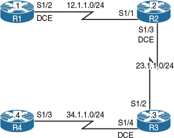
Figure 7-4 EIGRP Summarization Topology
Task 1
Figure 7-4 illustrates the topology used in the following tasks. Configure the loopback interfaces in Table 7-3 on R1 and advertise them in the EIGRP routing domain.
Table 7-3 Loopback Interfaces for R1

!On R1:
R1(config)# interface loopback0
R1(config-if)# ip address 1.1.0.1 255.255.255.0
R1(config-if)# interface loopback1
R1(config-if)# ip address 1.1.1.1 255.255.255.0
R1(config-if)# interface loopback2
R1(config-if)# ip address 1.1.2.1 255.255.255.0
R1(config-if)# interface loopback3
R1(config-if)# ip address 1.1.3.1 255.255.255.0
R1(config)# router eigrp 100
R1(config-router)# network 12.1.1.1 0.0.0.0
R1(config-router)# network 1.0.0.0
Task 2
Configure the loopback interfaces in Table 7-4 on R2 and advertise them in the EIGRP routing domain.
Table 7-4 Loopback Interfaces for R2

!On R2:
R2(config)# interface loopback0
R2(config-if)# ip address 2.2.4.2 255.255.255.0
R2(config-if)# interface loopback1
R2(config-if)# ip address 2.2.5.2 255.255.255.0
R2(config-if)# interface loopback2
R2(config-if)# ip address 2.2.6.2 255.255.255.0
R2(config-if)# interface loopback3
R2(config-if)# ip address 2.2.7.2 255.255.255.0
R2(config)# router eigrp 100
R2(config-router)# network 12.1.1.2 0.0.0.0
R2(config-router)# network 23.1.1.2 0.0.0.0
R2(config-router)# network 2.2.4.2 0.0.0.0
R2(config-router)# network 2.2.5.2 0.0.0.0
R2(config-router)# network 2.2.6.2 0.0.0.0
R2(config-router)# network 2.2.7.2 0.0.0.0
Task 3
Configure the loopback interfaces shown in Table 7-5 on R3 and advertise them in EIGRP 100.
Table 7-5 Loopback Interfaces for R3

!On R3:
R3(config)# interface loopback0
R3(config-if)# ip address 3.3.8.3 255.255.255.0
R3(config)# interface loopback1
R3(config-if)# ip address 3.3.9.3 255.255.255.0
R3(config)# interface loopback2
R3(config-if)# ip address 3.3.10.3 255.255.255.0
R3(config)# interface loopback3
R3(config-if)# ip address 3.3.11.3 255.255.255.0
R3(config)# router eigrp 100
R3(config-router)# network 23.1.1.3 0.0.0.0
R3(config-router)# network 34.1.1.3 0.0.0.0
R3(config-router)# network 3.3.8.3 0.0.0.0
R3(config-router)# network 3.3.9.3 0.0.0.0
R3(config-router)# network 3.3.10.3 0.0.0.0
R3(config-router)# network 3.3.11.3 0.0.0.0
Task 4
Configure the loopback interfaces in Table 7-6 on R4 and advertise them in EIGRP 100.
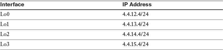
!On R4:
R4(config)# interface loopback0
R4(config-if)# ip address 4.4.12.4 255.255.255.0
R4(config)# interface loopback1
R4(config-if)# ip address 4.4.13.4 255.255.255.0
R4(config)# interface loopback2
R4(config-if)# ip address 4.4.14.4 255.255.255.0
R4(config)# interface loopback3
R4(config-if)# ip address 4.4.15.4 255.255.255.0
R4(config)# router eigrp 100
R4(config-router)# network 34.1.1.4 0.0.0.0
R4(config-router)# network 4.4.12.4 0.0.0.0
R4(config-router)# network 4.4.13.4 0.0.0.0
R4(config-router)# network 4.4.14.4 0.0.0.0
R4(config-router)# network 4.4.15.4 0.0.0.0
Let’s verify the configuration:
!On R4:
R4# show ip route eigrp | begin Gate
Gateway of last resort is not set
1.0.0.0/24 is subnetted, 4 subnets
D 1.1.0.0 [90/21664000] via 34.1.1.3, 00:08:22, Serial1/3
D 1.1.1.0 [90/21664000] via 34.1.1.3, 00:08:22, Serial1/3
D 1.1.2.0 [90/21664000] via 34.1.1.3, 00:08:22, Serial1/3
D 1.1.3.0 [90/21664000] via 34.1.1.3, 00:08:22, Serial1/3
2.0.0.0/24 is subnetted, 4 subnets
D 2.2.4.0 [90/21152000] via 34.1.1.3, 00:05:17, Serial1/3
D 2.2.5.0 [90/21152000] via 34.1.1.3, 00:05:17, Serial1/3
D 2.2.6.0 [90/21152000] via 34.1.1.3, 00:05:17, Serial1/3
D 2.2.7.0 [90/21152000] via 34.1.1.3, 00:05:17, Serial1/3
3.0.0.0/24 is subnetted, 4 subnets
D 3.3.8.0 [90/20640000] via 34.1.1.3, 00:03:44, Serial1/3
D 3.3.9.0 [90/20640000] via 34.1.1.3, 00:03:44, Serial1/3
D 3.3.10.0 [90/20640000] via 34.1.1.3, 00:03:44, Serial1/3
D 3.3.11.0 [90/20640000] via 34.1.1.3, 00:03:44, Serial1/3
12.0.0.0/24 is subnetted, 1 subnets
D 12.1.1.0 [90/21536000] via 34.1.1.3, 00:08:22, Serial1/3
23.0.0.0/24 is subnetted, 1 subnets
D 23.1.1.0 [90/21024000] via 34.1.1.3, 00:08:22, Serial1/3
!On R1:
R1# show ip route eigrp | begin Gate
Gateway of last resort is not set
2.0.0.0/24 is subnetted, 4 subnets
D 2.2.4.0 [90/20640000] via 12.1.1.2, 00:06:20, Serial1/2
D 2.2.5.0 [90/20640000] via 12.1.1.2, 00:06:20, Serial1/2
D 2.2.6.0 [90/20640000] via 12.1.1.2, 00:06:20, Serial1/2
D 2.2.7.0 [90/20640000] via 12.1.1.2, 00:06:20, Serial1/2
3.0.0.0/24 is subnetted, 4 subnets
D 3.3.8.0 [90/21152000] via 12.1.1.2, 00:04:47, Serial1/2
D 3.3.9.0 [90/21152000] via 12.1.1.2, 00:04:47, Serial1/2
D 3.3.10.0 [90/21152000] via 12.1.1.2, 00:04:47, Serial1/2
D 3.3.11.0 [90/21152000] via 12.1.1.2, 00:04:47, Serial1/2
4.0.0.0/24 is subnetted, 4 subnets
D 4.4.12.0 [90/21664000] via 12.1.1.2, 00:03:37, Serial1/2
D 4.4.13.0 [90/21664000] via 12.1.1.2, 00:03:37, Serial1/2
D 4.4.14.0 [90/21664000] via 12.1.1.2, 00:03:37, Serial1/2
D 4.4.15.0 [90/21664000] via 12.1.1.2, 00:03:37, Serial1/2
23.0.0.0/24 is subnetted, 1 subnets
D 23.1.1.0 [90/21024000] via 12.1.1.2, 00:09:47, Serial1/2
34.0.0.0/24 is subnetted, 1 subnets
D 34.1.1.0 [90/21536000] via 12.1.1.2, 00:09:25, Serial1/2
Task 5
Configure R2 such that it advertises a summary route for its loopback interfaces to R3.
Unlike OSPF, summarization can be performed on any router anywhere within the topology in EIGRP. Summarization is configured in the interface configuration mode, making it very specific. This means that only the neighbor(s) through that interface will receive the summary route.
!On R2:
R2(config)# interface serial1/3
R2(config-if)# ip summary-address eigrp 100 2.2.4.0 255.255.252.0
Let’s verify the configuration:
Note When summarization is configured, EIGRP will inject a discard route for loop avoidance, highlighted here.
!On R2:
R2# show ip route eigrp | include 2.2.4.0
D 2.2.4.0/22 is a summary, 00:01:17, Null0
R2# show ip route 2.2.4.0 255.255.252.0
Routing entry for 2.2.4.0/22
Known via "eigrp 100", distance 5, metric 128256, type internal
Redistributing via eigrp 100
Routing Descriptor Blocks:
* directly connected, via Null0
Route metric is 128256, traffic share count is 1
Total delay is 5000 microseconds, minimum bandwidth is 10000000 Kbit
Reliability 255/255, minimum MTU 9676 bytes
Loading 1/255, Hops 0
!On R3:
R3# show ip route eigrp | begin Gate
Gateway of last resort is not set
1.0.0.0/24 is subnetted, 4 subnets
D 1.1.0.0 [90/21152000] via 23.1.1.2, 00:11:43, Serial1/2
D 1.1.1.0 [90/21152000] via 23.1.1.2, 00:11:43, Serial1/2
D 1.1.2.0 [90/21152000] via 23.1.1.2, 00:11:43, Serial1/2
D 1.1.3.0 [90/21152000] via 23.1.1.2, 00:11:43, Serial1/2
2.0.0.0/22 is subnetted, 1 subnets
D 2.2.4.0 [90/20640000] via 23.1.1.2, 00:00:53, Serial1/2
4.0.0.0/24 is subnetted, 4 subnets
D 4.4.12.0 [90/20640000] via 34.1.1.4, 00:05:56, Serial1/4
D 4.4.13.0 [90/20640000] via 34.1.1.4, 00:05:56, Serial1/4
D 4.4.14.0 [90/20640000] via 34.1.1.4, 00:05:56, Serial1/4
D 4.4.15.0 [90/20640000] via 34.1.1.4, 00:05:56, Serial1/4
12.0.0.0/24 is subnetted, 1 subnets
D 12.1.1.0 [90/21024000] via 23.1.1.2, 00:11:43, Serial1/2
Task 6
R2 should summarize its loopback interfaces and advertise a single summary route plus all the specific routes of the summary to R1.
The leak-map option was introduced in IOS 12.3(14)T, and it must be configured under the physical interface and not a subinterface. Configuring the leak-map option allows us to advertise a component route (one or more specific networks of the summary route) that would otherwise be suppressed by manual summarization.
There are three rules to remember:
![]() If leak-map is configured to reference a route map that does not exist, only the summary route is advertised and the more specific routes are suppressed.
If leak-map is configured to reference a route map that does not exist, only the summary route is advertised and the more specific routes are suppressed.
![]() If leak-map is configured to reference a route map, and the route map is referencing an access list that does not exist, then the summary route plus all the specific routes are advertised.
If leak-map is configured to reference a route map, and the route map is referencing an access list that does not exist, then the summary route plus all the specific routes are advertised.
![]() If leak-map is configured to reference a route map, and the route map matches on an access list, all the permitted networks by the access list will be advertised along with the summary route.
If leak-map is configured to reference a route map, and the route map matches on an access list, all the permitted networks by the access list will be advertised along with the summary route.
!On R2:
R2(config)# interface serial1/1
R2(config-if)# ip summary-address eigrp 100 2.2.4.0 255.255.252.0 leak-map TEST21
R2(config)# route-map TEST21 permit 10
Note The leak-map option is referencing a route map, and the route map is not referencing an access list. Therefore, the summary route plus all the specific routes are advertised. If the route map references an access list that does not exist, you will see the same result.
Let’s verify the configuration:
!On R1:
R1# show ip route eigrp | begin Gate
Gateway of last resort is not set
2.0.0.0/8 is variably subnetted, 5 subnets, 2 masks
D 2.2.4.0/22 [90/20640000] via 12.1.1.2, 00:00:48, Serial1/2
D 2.2.4.0/24 [90/20640000] via 12.1.1.2, 00:00:28, Serial1/2
D 2.2.5.0/24 [90/20640000] via 12.1.1.2, 00:00:28, Serial1/2
D 2.2.6.0/24 [90/20640000] via 12.1.1.2, 00:00:28, Serial1/2
D 2.2.7.0/24 [90/20640000] via 12.1.1.2, 00:00:28, Serial1/2
3.0.0.0/24 is subnetted, 4 subnets
D 3.3.8.0 [90/21152000] via 12.1.1.2, 00:11:39, Serial1/2
D 3.3.9.0 [90/21152000] via 12.1.1.2, 00:11:39, Serial1/2
D 3.3.10.0 [90/21152000] via 12.1.1.2, 00:11:39, Serial1/2
D 3.3.11.0 [90/21152000] via 12.1.1.2, 00:11:39, Serial1/2
4.0.0.0/24 is subnetted, 4 subnets
D 4.4.12.0 [90/21664000] via 12.1.1.2, 00:10:29, Serial1/2
D 4.4.13.0 [90/21664000] via 12.1.1.2, 00:10:29, Serial1/2
D 4.4.14.0 [90/21664000] via 12.1.1.2, 00:10:29, Serial1/2
D 4.4.15.0 [90/21664000] via 12.1.1.2, 00:10:29, Serial1/2
23.0.0.0/24 is subnetted, 1 subnets
D 23.1.1.0 [90/21024000] via 12.1.1.2, 00:16:39, Serial1/2
34.0.0.0/24 is subnetted, 1 subnets
D 34.1.1.0 [90/21536000] via 12.1.1.2, 00:16:17, Serial1/2
Task 7
Configure R4 to summarize its loopback interfaces and advertise a summary route plus network 4.4.13.0/24 to R3.
!On R4:
R4# show access-lists
R4(config)# interface serial1/3
R4(config-if)# ip summary-address eigrp 100 4.4.12.0 255.255.252.0 leak-map TEST43
R4(config)# access-list 13 permit 4.4.13.0 0.0.0.255
R4(config)# route-map TEST43 permit 10
R4(config-route-map)# match ip address 13
Let’s verify the configuration:
!On R4:
R4# show ip route eigrp | include Null0
D 4.4.12.0/22 is a summary, 00:01:49, Null0
The output of the preceding show command reveals the Null0 discard route that is created whenever summarization is configured:
!On R3:
R3# show ip route eigrp | begin Gate
Gateway of last resort is not set
1.0.0.0/24 is subnetted, 4 subnets
D 1.1.0.0 [90/21152000] via 23.1.1.2, 00:19:34, Serial1/2
D 1.1.1.0 [90/21152000] via 23.1.1.2, 00:19:34, Serial1/2
D 1.1.2.0 [90/21152000] via 23.1.1.2, 00:19:34, Serial1/2
D 1.1.3.0 [90/21152000] via 23.1.1.2, 00:19:34, Serial1/2
2.0.0.0/22 is subnetted, 1 subnets
D 2.2.4.0 [90/20640000] via 23.1.1.2, 00:08:44, Serial1/2
4.0.0.0/8 is variably subnetted, 2 subnets, 2 masks
D 4.4.12.0/22 [90/20640000] via 34.1.1.4, 00:01:21, Serial1/4
D 4.4.13.0/24 [90/20640000] via 34.1.1.4, 00:00:57, Serial1/4
12.0.0.0/24 is subnetted, 1 subnets
D 12.1.1.0 [90/21024000] via 23.1.1.2, 00:19:34, Serial1/2
Task 8
Configure R3 to summarize its loopback interfaces and advertise a single summary plus 3.3.10.0/24 and 3.3.11.0/24 to R4:
!On R3:
R3# show access-lists
R3(config)# interface serial1/4
R3(config-if)# ip summary-address eigrp 100 3.3.8.0 255.255.252.0 leak-map TEST34
R3(config-if)# access-list 34 permit 3.3.10.0 0.0.0.255
R3(config)# access-list 34 permit 3.3.11.0 0.0.0.255
R3(config)# route-map TEST34 permit 10
R3(config-route-map)# match ip address 34
Let’s verify the configuration:
!On R4:
R4# show ip route eigrp | begin Gate
Gateway of last resort is not set
1.0.0.0/24 is subnetted, 4 subnets
D 1.1.0.0 [90/21664000] via 34.1.1.3, 00:22:02, Serial1/3
D 1.1.1.0 [90/21664000] via 34.1.1.3, 00:22:02, Serial1/3
D 1.1.2.0 [90/21664000] via 34.1.1.3, 00:22:02, Serial1/3
D 1.1.3.0 [90/21664000] via 34.1.1.3, 00:22:02, Serial1/3
2.0.0.0/22 is subnetted, 1 subnets
D 2.2.4.0 [90/21152000] via 34.1.1.3, 00:11:11, Serial1/3
3.0.0.0/8 is variably subnetted, 3 subnets, 2 masks
D 3.3.8.0/22 [90/20640000] via 34.1.1.3, 00:00:47, Serial1/3
D 3.3.10.0/24 [90/20640000] via 34.1.1.3, 00:00:24, Serial1/3
D 3.3.11.0/24 [90/20640000] via 34.1.1.3, 00:00:24, Serial1/3
4.0.0.0/8 is variably subnetted, 9 subnets, 3 masks
D 4.4.12.0/22 is a summary, 00:03:48, Null0
12.0.0.0/24 is subnetted, 1 subnets
D 12.1.1.0 [90/21536000] via 34.1.1.3, 00:22:02, Serial1/3
23.0.0.0/24 is subnetted, 1 subnets
D 23.1.1.0 [90/21024000] via 34.1.1.3, 00:22:02, Serial1/3
Task 9
Configure R1 to inject a default route into the EIGRP 100 routing domain. Do not use any global or router-configuration command as part of the solution to accomplish this task.
The following command summarizes all Class A, Class B, and Class C networks; it’s the mother of all summaries:
!On R1:
R1(config)# interface serial1/2
R1(config-if)# ip summary-address eigrp 100 0.0.0.0 0.0.0.0
Let’s look at the discard route:
!On R1:
R1# show ip route eigrp | include Null0
D* 0.0.0.0/0 is a summary, 00:03:19, Null0
!On R2:
R2# show ip route eigrp | include Serial1/1
D* 0.0.0.0/0 [90/20640000] via 12.1.1.1, 00:00:37, Serial1/1
Note All the specific routes are suppressed and only the summary route is advertised.
Erase the startup config and reload the routers before proceeding to the next lab.
Lab 7-5: EIGRP Authentication
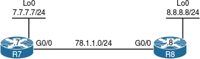
Figure 7-5 EIGRP Authentication Topology
Task 1
Configure the routers based on the diagram shown in Figure 7-5.
!On SW1:
SW1(config)# interface range fastethernet0/7 - 8
SW1(config-if)# switchport mode access
SW1(config-if)# switchport access vlan 78
SW1(config-if)# no shutdown
!On R7:
R7(config)# interface gigabitethernet0/0
R7(config-if)# ip address 78.1.1.7 255.255.255.0
R7(config-if)# no shutdown
R7(config)# interface loopback0
R7(config-if)# ip address 7.7.7.7 255.255.255.0
!On R8:
R8(config)# interface gigabitethernet0/0
R8(config-if)# ip address 78.1.1.8 255.255.255.0
R8(config-if)# no shutdown
R8(config)# interface loopback0
R8(config-if)# ip address 8.8.8.8 255.255.255.0
Let’s verify the configuration:
!On R7:
R7# ping 78.1.1.8
Type escape sequence to abort.
Sending 5, 100-byte ICMP Echos to 78.1.1.8, timeout is 2 seconds:
.!!!!
Success rate is 80 percent (4/5), round-trip min/avg/max = 1/1/1 ms
Task 2
Configure EIGRP in AS 100 on both routers and advertise their directly connected networks. You should use classic mode EIGRP to accomplish this task:
!On R7:
R7(config)# router eigrp 100
R7(config-router)# network 78.1.1.7 0.0.0.0
R7(config-router)# network 7.7.7.7 0.0.0.0
!On R8:
R8(config)# router eigrp 100
R8(config-router)# network 78.1.1.8 0.0.0.0
R8(config-router)# network 8.8.8.8 0.0.0.0
You should see the following console message:
%DUAL-5-NBRCHANGE: EIGRP-IPv4 100: Neighbor 78.1.1.7 (GigabitEthernet0/0) is up: new adjacency
Let’s verify the configuration:
!On R7:
R7# show ip route eigrp | begin Gate
Gateway of last resort is not set
8.0.0.0/24 is subnetted, 1 subnets
D 8.8.8.0 [90/156160] via 78.1.1.8, 00:01:18, GigabitEthernet0/0
Task 3
Enable MD5 EIGRP authentication between R7 and R8. Use “cisco” as the password.
EIGRP uses keychain-based authentication, just like RIPv2:
!On Both Routers:
Rx(config)# key chain TST
Rx(config-keychain)# key 1
Rx(config-keychain-key)# key-string cisco
Rx(config)# interface gigabitethernet0/0
Rx(config-if)# ip authentication key-chain eigrp 100 TST
Rx(config-if)# ip authentication mode eigrp 100 md5
Let’s verify the configuration:
!On R7:
R7# show ip route eigrp | begin Gate
Gateway of last resort is not set
8.0.0.0/24 is subnetted, 1 subnets
D 8.8.8.0 [90/156160] via 78.1.1.8, 00:00:33, GigabitEthernet0/0
R7# show ip eigrp interface detail | include Authen
Authentication mode is md5, key-chain is "TST"
Authentication mode is not set
Task 4
Configure the strongest authentication method on R7 and R8. You must use “C?IE” as the password.
In EIGRP, when authentication is enabled, every packet that is exchanged between the neighbors must be authenticated to ensure the identity of the neighbor. This is done by using identical pre-shared authentication keys, meaning the two neighbors must use the same pre-shared authentication key. EIGRP authentication is configured in the interface-configuration mode. This means that packets exchanged between neighbors connected through an interface are authenticated.
EIGRP supports MD5 authentication in the classic mode, and the Hashed Message Authentication Code-Secure Hash Algorithm-256 (HMAC-SHA-256) authentication method in the named mode. Because the task states that the strongest authentication method must be used, it is referring to HMAC-SHA-256.
Before authentication is configured, you must remove EIGRP and reconfigure EIGRP in the named mode. Let’s configure this task:
!On R8:
R8(config)# no router eigrp 100
R8(config)# router eigrp tst
R8(config-router)# address-family ipv4 unicast as 100
R8(config-router-af)# network 78.1.1.8 0.0.0.0
R8(config-router-af)# network 8.8.8.8 0.0.0.0
When configuring the address family, you have two choices to identify the AS number: One way is to use the autonomous-system keyword at the end, and the second choice is to use the as keyword.
!On R7:
R7(config)# no router eigrp 100
R7(config)# router eigrp tst
R7(config-router)# address-family ipv4 unicast as 100
R7(config-router-af)# network 78.1.1.7 0.0.0.0
Because authentication is configured in the interface-configuration mode, you must enter the address-family mode for a given interface:
!On R7 and R8:
Rx(config)# router eigrp tst
Rx(config-router)# address-family ipv4 unicast as 100
Rx(config-router-af)# af-interface GigabitEthernet0/0
Rx(config-router-af-interface)# authentication mode hmac-sha-256 C?IE
So how do you enter “C?IE”? Before pressing the ? key, you must press Esc and then let go, then press q and let go before a “?” can be entered.
Let’s verify the configuration:
!On R7:
R7# show ip route eigrp | begin Gate
Gateway of last resort is not set
8.0.0.0/24 is subnetted, 1 subnets
D 8.8.8.0 [90/103040] via 78.1.1.8, 00:01:21, GigabitEthernet0/0
Erase the startup config and reload the routers before proceeding to the next lab.
Lab 7-6: Default Route Injection

Figure 7-6 Default Route Injection
Task 1
Figure 7-6 illustrates the topology used in the following tasks. Configure EIGRP in AS 100 on both routers and advertise their directly connected networks.
!On R1:
R1(config)# router eigrp 100
R1(config-router)# network 12.1.1.1 0.0.0.0
R1(config-router)# network 1.1.1.1 0.0.0.0
!On R2:
R2(config)# router eigrp 100
R2(config-router)# network 2.2.2.2 0.0.0.0
R2(config-router)# network 12.1.1.2 0.0.0.0
Let’s verify the configuration:
!On R1:
R1# show ip route eigrp | begin Gate
D 2.0.0.0/8 [90/20640000] via 12.1.1.2, 00:00:20, Serial1/2
Task 2
Configure R1 to inject a default route into the EIGRP routing domain.
There are many ways to inject a default route in EIGRP; in this task, we’ll test four ways of injecting a default route.
Option #1
One way to inject a default route into EIGRP is to configure a static default route pointing to Null0 and then redistribute the default route into EIGRP. When redistributing a static, connected, or EIGRP route for another AS, the metric does not need to be assigned. The default route will be an external EIGRP route.
!On R1:
R1(config)# ip route 0.0.0.0 0.0.0.0 null0
R1(config)# router eigrp 100
R1(config-router)# redistribute static
Let’s verify the configuration:
!On R2:
R2# show ip route eigrp | begin Gate
Gateway of last resort is 12.1.1.1 to network 0.0.0.0
D*EX 0.0.0.0/0 [170/20512000] via 12.1.1.1, 00:03:01, Serial1/1
D 1.0.0.0/8 [90/20640000] via 12.1.1.1, 00:04:52, Serial1/1
R2# show ip eigrp topology 0.0.0.0/0
EIGRP-IPv4 Topology Entry for AS(100)/ID(2.2.2.2) for 0.0.0.0/0
State is Passive, Query origin flag is 1, 1 Successor(s), FD is 20512000
Descriptor Blocks:
12.1.1.1 (Serial1/1), from 12.1.1.1, Send flag is 0x0
Composite metric is (20512000/256), route is External
Vector metric:
Minimum bandwidth is 128 Kbit
Total delay is 20000 microseconds
Reliability is 0/255
Load is 1/255
Minimum MTU is 1500
Hop count is 1
Originating router is 1.1.1.1
External data:
AS number of route is 0
External protocol is Static, external metric is 0
Administrator tag is 0 (0x00000000)
Exterior flag is set
Option #2
The second method for injecting a default route into EIGRP is to configure a network command with 0.0.0.0. You must have the static default route configured; otherwise, with network 0.0.0.0, all existing and future directly connected interfaces will be advertised in the configured AS. The default route will be an internal EIGRP route.
R1(config)# ip route 0.0.0.0 0.0.0.0 null0
R1(config)# router eigrp 100
R1(config-router)# no redistribute static
R1(config-router)# network 0.0.0.0
Let’s verify the configuration:
!On R2:
R2# show ip route eigrp | begin Gate
Gateway of last resort is 12.1.1.1 to network 0.0.0.0
D* 0.0.0.0/0 [90/20512000] via 12.1.1.1, 00:00:09, Serial1/1
D 1.0.0.0/8 [90/20640000] via 12.1.1.1, 00:11:11, Serial1/1
R2# sh ip eigrp topology 0.0.0.0/0
EIGRP-IPv4 Topology Entry for AS(100)/ID(2.2.2.2) for 0.0.0.0/0
State is Passive, Query origin flag is 1, 1 Successor(s), FD is 20512000
Descriptor Blocks:
12.1.1.1 (Serial1/1), from 12.1.1.1, Send flag is 0x0
Composite metric is (20512000/256), route is Internal
Vector metric:
Minimum bandwidth is 128 Kbit
Total delay is 20000 microseconds
Reliability is 0/255
Load is 1/255
Minimum MTU is 1500
Hop count is 1
Originating router is 1.1.1.1
Exterior flag is set
Option #3
The third method for injecting a default route into EIGRP is to configure the ip summary-address eigrp interface-configuration command. With this command, you are summarizing all Class A, B, and C networks. This means that you are suppressing every route in your routing table, but if you must advertise a specific network, you must leak it. The default route will be an internal EIGRP route.
!On R1:
R1(config)# no ip route 0.0.0.0 0.0.0.0 null0
R1(config)# interface serial1/2
R1(config-if)# ip summary-address eigrp 100 0.0.0.0 0.0.0.0
Let’s verify the configuration:
!On R2:
R2# show ip route eigrp | begin Gate
Gateway of last resort is 12.1.1.1 to network 0.0.0.0
D* 0.0.0.0/0 [90/20640000] via 12.1.1.1, 00:00:36, Serial1/1
R2# show ip eigrp topology 0.0.0.0/0
EIGRP-IPv4 Topology Entry for AS(100)/ID(2.2.2.2) for 0.0.0.0/0
State is Passive, Query origin flag is 1, 1 Successor(s), FD is 20640000
Descriptor Blocks:
12.1.1.1 (Serial1/1), from 12.1.1.1, Send flag is 0x0
Composite metric is (20640000/128256), route is Internal
Vector metric:
Minimum bandwidth is 128 Kbit
Total delay is 25000 microseconds
Reliability is 255/255
Load is 1/255
Minimum MTU is 1500
Hop count is 1
Originating router is 1.1.1.1
As you can see, all the specific routes are suppressed.
Option #4
The fourth method of injecting a default route is to use ip default-network. In this method, R1 is injecting a candidate default, and the candidate route must be advertised to R2. Let’s configure this and verify:
R1(config)# interface serial1/2
R1(config-if)# no ip summary-address eigrp 100 0.0.0.0 0.0.0.0
Because network 1.0.0.0/8 is already advertised to R2, this network can be set to be the candidate network.
R1(config)# ip default-network 1.0.0.0
R1(config)# router eigrp 100
R1(config-router)# network 1.0.0.0
Note The network specified must be a classful network, meaning that it cannot be a subnetted network; it must be a major network (either Class A, B, or C).
Let’s verify the configuration:
!On R2:
R2# show ip route eigrp | begin Gate
Gateway of last resort is not set
D* 1.0.0.0/8 [90/20640000] via 12.1.1.1, 00:05:24, Serial1/1
The asterisk next to the letter D means “candidate default.” This means that if R2 doesn’t have the route it needs to reach in its routing table, it will use the candidate default (in this case, network 1.0.0.0). Because R1 was the router that advertised network 1.0.0.0/8 to R2, R2 will use R1 to reach that network.
Erase the startup config and reload the routers before proceeding to the next lab.
Lab 7-7: EIGRP Stub
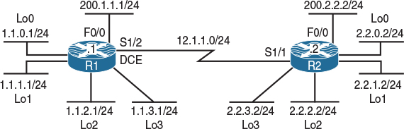
Figure 7-7 EIGRP Stub Topology
Task 1
Figure 7-7 illustrates the topology used in the following tasks. Configure EIGRP AS 100 on the serial interface and all loopback interfaces of these two routers. R1 should configure EIGRP using the classic method, and R2 should use EIGRP named mode configuration to accomplish this task. Do not run EIGRP on the F0/0 interfaces of these two routers.
!On R1:
R1(config)# router eigrp 100
R1(config-router)# network 1.1.0.1 0.0.0.0
R1(config-router)# network 1.1.1.1 0.0.0.0
R1(config-router)# network 1.1.2.1 0.0.0.0
R1(config-router)# network 1.1.3.1 0.0.0.0
R1(config-router)# network 12.1.1.1 0.0.0.0
!On R2:
R2(config)# router eigrp AS100
R2(config-router)# address-family ipv4 unicast autonomous-system 100
R2(config-router-af)# network 2.2.0.2 0.0.0.0
R2(config-router-af)# network 2.2.1.2 0.0.0.0
R2(config-router-af)# network 2.2.2.2 0.0.0.0
R2(config-router-af)# network 2.2.3.2 0.0.0.0
R2(config-router-af)# network 12.1.1.2 0.0.0.0
You should see the following console message:
%DUAL-5-NBRCHANGE: EIGRP-IPv4 100: Neighbor 12.1.1.1 (Serial1/1) is up: new adjacency
Let’s verify the configuration:
!On R1:
R1# show ip route eigrp | begin Gate
Gateway of last resort is not set
2.0.0.0/24 is subnetted, 4 subnets
D 2.2.0.0 [90/20640000] via 12.1.1.2, 00:03:18, Serial1/2
D 2.2.1.0 [90/20640000] via 12.1.1.2, 00:03:18, Serial1/2
D 2.2.2.0 [90/20640000] via 12.1.1.2, 00:03:18, Serial1/2
D 2.2.3.0 [90/20640000] via 12.1.1.2, 00:03:18, Serial1/2
!On R2:
R2# show ip route eigrp | begin Gate
Gateway of last resort is not set
1.0.0.0/24 is subnetted, 4 subnets
D 1.1.0.0 [90/20640000] via 12.1.1.1, 00:03:42, Serial1/1
D 1.1.1.0 [90/20640000] via 12.1.1.1, 00:03:42, Serial1/1
D 1.1.2.0 [90/20640000] via 12.1.1.1, 00:03:42, Serial1/1
D 1.1.3.0 [90/20640000] via 12.1.1.1, 00:03:42, Serial1/1
Task 2
Configure R1 and R2 to summarize their loopback interfaces in EIGRP:
!On R1:
R1(config)# interface serial1/2
R1(config-if)# ip summary-address eigrp 100 1.1.0.0 255.255.252.0
!On R2:
R2(config)# router eigrp AS100
R2(config-router)# address-family ipv4 unicast autonomous-system 100
R2(config-router-af)# af-interface serial1/1
R2(config-router-af-interface)# summary-address 2.2.0.0 255.255.252.0
Let’s verify the configuration:
!On R1:
R1# show ip route eigrp | begin Gate
Gateway of last resort is not set
1.0.0.0/8 is variably subnetted, 9 subnets, 3 masks
D 1.1.0.0/22 is a summary, 00:00:09, Null0
2.0.0.0/22 is subnetted, 1 subnets
D 2.2.0.0 [90/20640000] via 12.1.1.2, 00:01:54, Serial1/2
!On R2:
R2# show ip route eigrp | begin Gate
Gateway of last resort is not set
1.0.0.0/22 is subnetted, 1 subnets
D 1.1.0.0 [90/20640000] via 12.1.1.1, 00:00:27, Serial1/1
2.0.0.0/8 is variably subnetted, 9 subnets, 3 masks
D 2.2.0.0/22 is a summary, 00:02:13, Null0
Task 3
Configure the static routes shown in Table 7-7 on R1 and R2 and redistribute them into EIGRP.

!On R1:
R1(config)# ip route 11.0.0.0 255.0.0.0 fastEthernet0/0
R1(config)# router eigrp 100
R1(config-router)# redistribute static
!On R2:
R2(config)# ip route 22.0.0.0 255.0.0.0 fastEthernet0/0
R2(config)# router eigrp AS100
R2(config-router)# address-family ipv4 unicast autonomous-system 100
R2(config-router-af)# topology base
R2(config-router-af-topology)# redistribute static
Let’s verify the configuration:
!On R1:
R1# show ip route eigrp | begin Gate
Gateway of last resort is not set
1.0.0.0/8 is variably subnetted, 9 subnets, 3 masks
D 1.1.0.0/22 is a summary, 00:03:09, Null0
2.0.0.0/22 is subnetted, 1 subnets
D 2.2.0.0 [90/20640000] via 12.1.1.2, 00:04:54, Serial1/2
D EX 22.0.0.0/8 [170/20514560] via 12.1.1.2, 00:00:34, Serial1/2
!On R2:
R2# show ip route eigrp | begin Gate
Gateway of last resort is not set
1.0.0.0/22 is subnetted, 1 subnets
D 1.1.0.0 [90/20640000] via 12.1.1.1, 00:02:44, Serial1/1
2.0.0.0/8 is variably subnetted, 9 subnets, 3 masks
D 2.2.0.0/22 is a summary, 00:04:30, Null0
D EX 11.0.0.0/8 [170/20514560] via 12.1.1.1, 00:01:00, Serial1/1
Task 4
Advertise the FastEthernet interfaces of these two routers in RIPv2 and disable auto-summarization. You should redistribute RIP into EIGRP. Use any metric for redistributed routes.
!On R1:
R1(config)# router rip
R1(config-router)# no auto-summary
R1(config-router)# version 2
R1(config-router)# network 200.1.1.0
R1(config)# router eigrp 100
R1(config-router)# redistribute rip metric 1 1 1 1 1
!On R2:
R2(config)# router rip
R2(config-router)# no auto-summary
R2(config-router)# version 2
R2(config-router)# network 200.2.2.0
R2(config)# router eigrp AS100
R2(config-router)# address-family ipv4 unicast autonomous-system 100
R2(config-router-af)# topology base
R2(config-router-af-topology)# redistribute rip metric 1 1 1 1 1
Let’s verify the configuration:
!On R1:
R1# show ip route eigrp | begin Gate
Gateway of last resort is not set
1.0.0.0/8 is variably subnetted, 9 subnets, 3 masks
D 1.1.0.0/22 is a summary, 00:06:20, Null0
2.0.0.0/22 is subnetted, 1 subnets
D 2.2.0.0 [90/20640000] via 12.1.1.2, 00:08:05, Serial1/2
D EX 22.0.0.0/8 [170/20514560] via 12.1.1.2, 00:03:45, Serial1/2
D EX 200.2.2.0/24 [170/2560512256] via 12.1.1.2, 00:00:29, Serial1/2
!On R2:
R2# show ip route eigrp | begin Gate
Gateway of last resort is not set
1.0.0.0/22 is subnetted, 1 subnets
D 1.1.0.0 [90/20640000] via 12.1.1.1, 00:06:48, Serial1/1
2.0.0.0/8 is variably subnetted, 9 subnets, 3 masks
D 2.2.0.0/22 is a summary, 00:08:34, Null0
D EX 11.0.0.0/8 [170/20514560] via 12.1.1.1, 00:05:04, Serial1/1
D EX 200.1.1.0/24 [170/2560512256] via 12.1.1.1, 00:01:43, Serial1/1
Task 5
Configure EIGRP stub routing on R1 using the eigrp stub connected option. Test this option and verify the routes in the routing tables of both routers.
!On R1:
R1(config)# router eigrp 100
R1(config-router)# eigrp stub connected
You should see the following console message stating that the neighbor adjacency was reset:
%DUAL-5-NBRCHANGE: EIGRP-IPv4 100: Neighbor 12.1.1.2 (Serial1/2) is down: peer info changed
%DUAL-5-NBRCHANGE: EIGRP-IPv4 100: Neighbor 12.1.1.2 (Serial1/2) is up: new adjacency
The eigrp stub routing can also be configured in EIGRP named mode, but in this case it is only configured on R1. The following shows how EIGRP stub routing can be configured in an EIGRP named configuration:
R2(config)# router eigrp AS100
R2(config-router)# address-family ipv4 unicast autonomous-system 100
R2(config-router-af)# eigrp stub ?
connected Do advertise connected routes
leak-map Allow dynamic prefixes based on the leak-map
receive-only Set receive only neighbor
redistributed Do advertise redistributed routes
static Do advertise static routes
summary Do advertise summary routes
Let’s verify the configuration:
!On R2:
R2# show ip route eigrp | begin Gate
Gateway of last resort is not set
1.0.0.0/24 is subnetted, 4 subnets
D 1.1.0.0 [90/20640000] via 12.1.1.1, 00:02:06, Serial1/1
D 1.1.1.0 [90/20640000] via 12.1.1.1, 00:02:06, Serial1/1
D 1.1.2.0 [90/20640000] via 12.1.1.1, 00:02:06, Serial1/1
D 1.1.3.0 [90/20640000] via 12.1.1.1, 00:02:06, Serial1/1
2.0.0.0/8 is variably subnetted, 9 subnets, 3 masks
D 2.2.0.0/22 is a summary, 00:11:21, Null0
Note Only the directly connected networks that R1 used a network command to advertise were advertised to R2.
!On R1:
R1# show ip route eigrp | begin Gate
Gateway of last resort is not set
1.0.0.0/8 is variably subnetted, 9 subnets, 3 masks
D 1.1.0.0/22 is a summary, 00:10:09, Null0
2.0.0.0/22 is subnetted, 1 subnets
D 2.2.0.0 [90/20640000] via 12.1.1.2, 00:02:39, Serial1/2
D EX 22.0.0.0/8 [170/20514560] via 12.1.1.2, 00:02:39, Serial1/2
D EX 200.2.2.0/24 [170/2560512256] via 12.1.1.2, 00:02:39, Serial1/2
Note The routing table of R1 was not affected at all.
Task 6
Remove the eigrp stub connected option configured in the previous task and then reconfigure EIGRP stub routing on R1 using the eigrp stub summary option. Test this option and verify the routes in the routing tables of both routers:
!On R1:
R1(config)# router eigrp 100
R1(config-router)# no eigrp stub connected
R1(config-router)# eigrp stub summary
Let’s verify the configuration:
!On R2:
R2# show ip route eigrp | include 12.1.1.1
Gateway of last resort is not set
1.0.0.0/22 is subnetted, 1 subnets
D 1.1.0.0 [90/20640000] via 12.1.1.1, 00:00:17, Serial1/1
2.0.0.0/8 is variably subnetted, 9 subnets, 3 masks
D 2.2.0.0/22 is a summary, 00:15:23, Null0
!On R1:
R1# show ip route eigrp | begin Gate
Gateway of last resort is not set
1.0.0.0/8 is variably subnetted, 9 subnets, 3 masks
D 1.1.0.0/22 is a summary, 01:12:59, Null0
2.0.0.0/22 is subnetted, 1 subnets
D 2.2.0.0 [90/20640000] via 12.1.1.2, 00:00:57, Serial1/2
D EX 22.0.0.0/8 [170/20514560] via 12.1.1.2, 00:00:57, Serial1/2
D EX 200.2.2.0/24 [170/2560512256] via 12.1.1.2, 00:00:57, Serial1/2
By looking at the routing table of these two routers, you can clearly see that only the summarized route(s) were advertised to R2, but once again the routing table of R1 was not affected at all.
Task 7
Remove the eigrp stub summary option configured in the previous task and reconfigure EIGRP stub routing on R1 using eigrp stub static. Test this option and verify the routes in the routing tables of both routers.
!On R1:
R1(config)# router eigrp 100
R1(config-router)# no eigrp stub summary
R1(config-router)# eigrp stub static
Let’s verify the configuration:
!On R2:
R2# show ip route eigrp | begin Gate
Gateway of last resort is not set
2.0.0.0/8 is variably subnetted, 9 subnets, 3 masks
D 2.2.0.0/22 is a summary, 00:17:25, Null0
D EX 11.0.0.0/8 [170/20514560] via 12.1.1.1, 00:00:09, Serial1/1
!On R1:
R1# show ip route eigrp | begin Gate
Gateway of last resort is not set
1.0.0.0/8 is variably subnetted, 9 subnets, 3 masks
D 1.1.0.0/22 is a summary, 01:16:33, Null0
2.0.0.0/22 is subnetted, 1 subnets
D 2.2.0.0 [90/20640000] via 12.1.1.2, 00:01:41, Serial1/2
D EX 22.0.0.0/8 [170/20514560] via 12.1.1.2, 00:01:41, Serial1/2
D EX 200.2.2.0/24 [170/2560512256] via 12.1.1.2, 00:01:41, Serial1/2
The output of the preceding show command reveals that R1’s routing table was not affected at all, but R2 received the static routes that R1 redistributed into its routing table.
Note The routing protocol that is redistributed into EIGRP is not advertised and only the static routes are advertised.
Task 8
Remove the eigrp stub static option configured in the previous task and reconfigure EIGRP stub routing on R1 using eigrp stub redistributed. Test this option and verify the routes in the routing tables of both routers:
!On R1:
R1(config)# router eigrp 100
R1(config-router)# no eigrp stub static
R1(config-router)# eigrp stub redistributed
Let’s verify the configuration:
!On R2:
R2# show ip route eigrp | begin Gate
Gateway of last resort is not set
2.0.0.0/8 is variably subnetted, 9 subnets, 3 masks
D 2.2.0.0/22 is a summary, 00:20:05, Null0
D EX 11.0.0.0/8 [170/20514560] via 12.1.1.1, 00:00:10, Serial1/1
D EX 200.1.1.0/24 [170/2560512256] via 12.1.1.1, 00:00:10, Serial1/1
Note All the redistributed routes are advertised to R2, which means that the static routes and the routing protocols that were redistributed into EIGRP were advertised with this option.
Task 9
Remove the eigrp stub redistributed option configured in the previous task and reconfigure EIGRP stub routing on R1 using eigrp stub receive-only. Test this option and verify the routes in the routing tables of both routers:
!On R1:
R1(config)# router eigrp 100
R1(config-router)# no eigrp stub redistributed
R1(config-router)# eigrp stub receive-only
Let’s verify the configuration:
!On R2:
R2# show ip route eigrp | begin Gate
Gateway of last resort is not set
2.0.0.0/8 is variably subnetted, 9 subnets, 3 masks
D 2.2.0.0/22 is a summary, 00:21:28, Null0
You can clearly see that nothing was advertised to R2. With this option configured on R1, R1 receives all the routes from R2 but does not advertise any routes to R2.
!On R1:
R1# show ip route eigrp | begin Gate
Gateway of last resort is not set
1.0.0.0/8 is variably subnetted, 9 subnets, 3 masks
D 1.1.0.0/22 is a summary, 01:31:37, Null0
2.0.0.0/22 is subnetted, 1 subnets
D 2.2.0.0 [90/20640000] via 12.1.1.2, 00:01:27, Serial1/2
D EX 22.0.0.0/8 [170/20514560] via 12.1.1.2, 00:01:27, Serial1/2
D EX 200.2.2.0/24 [170/2560512256] via 12.1.1.2, 00:01:27, Serial1/2
Task 10
Remove the eigrp stub receive-only option configured in the previous task and reconfigure EIGRP stub routing on R1 using eigrp stub. Test this option and verify the routes in the routing tables of both routers:
!On R1:
R1(config)# router eigrp 100
R1(config-router)# no eigrp stub receive-only
R1(config-router)# eigrp stub
Let’s verify the configuration:
!On R2:
R2# show ip route eigrp | begin Gate
Gateway of last resort is not set
1.0.0.0/22 is subnetted, 1 subnets
D 1.1.0.0 [90/20640000] via 12.1.1.1, 00:00:05, Serial1/1
2.0.0.0/8 is variably subnetted, 9 subnets, 3 masks
D 2.2.0.0/22 is a summary, 00:22:37, Null0
Note All the directly connected routes and the summary route are advertised to R2. The reason you only see a single summary route is because when summarization is performed, the specific routes that are included in the summary are suppressed. To prove this fact, let’s configure the loopback100 interface on R1 and assign an IP address of 100.1.1.1/24 and advertise this route in EIGRP AS 100. If this is performed successfully, R2 should see the summary plus the 100.1.1.0/24 routes:
!On R1:
R1(config)# interface loopback100
R1(config-if)# ip address 100.1.1.1 255.255.255.0
R1(config)# router eigrp 100
R1(config-router)# network 100.1.1.1 0.0.0.0
Let’s verify the configuration:
!On R2:
R2# show ip route eigrp | begin Gate
Gateway of last resort is not set
1.0.0.0/22 is subnetted, 1 subnets
D 1.1.0.0 [90/20640000] via 12.1.1.1, 00:01:36, Serial1/1
2.0.0.0/8 is variably subnetted, 9 subnets, 3 masks
D 2.2.0.0/22 is a summary, 00:24:08, Null0
100.0.0.0/24 is subnetted, 1 subnets
D 100.1.1.0 [90/20640000] via 12.1.1.1, 00:00:10, Serial1/1
Erase the startup config and reload the routers before proceeding to the next lab.