Chapter 11 IPv6
Lab 11-1: Acquiring an IPv6 Address
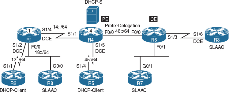
Figure 11-1 Acquiring an IPv6 Address
Figure 11-1 illustrates the topology that will be used in the following lab.
Modified EUI-64 Addressing
Modified Extended Unique Identifier 64 (EUI-64) is the process that allows a host to assign itself a unique IPv6 address. The host’s MAC address is converted into a 64-bit identifier, called a Modified EUI-64, and this value is appended to a 64-bit network prefix learned by other means. This feature is an enhancement over IPv4 because it eliminates the need for manual configuration or DHCP. The IPv6 Modified EUI-64 format address is created based on the 48-bit MAC address of the interface. The MAC address is first separated into two 24-bit groups, the first being the OUI (organizationally unique identifier) and the other being NIC-specific. The 16-bit value of FFFE is then inserted between these two 24-bit groups to form the 64-bit EUI address. IEEE has chosen FFFE as a reserved value that can only appear in EUI-64 generated from the EUI-48 MAC address.
Finally, the seventh bit from the left, or the universal/local (U/L) bit, needs to be inverted. This process can be seen in Figure 11-2. This bit identifies whether this Modified EUI-64 interface identifier is officially assigned or locally generated; in other words, whether it is universally or locally administered. If it is 0, the address is locally administered; if it is 1, the address is globally unique. It is worth noticing that in the original OUI portion, the globally unique addresses assigned by the IEEE have their U/L bit always set to 0, whereas locally created addresses have it set to 1. In other words, the meaning of the U/L bit in the Modified EUI-64 is inverted when compared to the meaning assigned by IEEE. This is the reason for calling this address the Modified EUI-64. Therefore, when the bit is inverted, it maintains its original value.
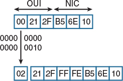
Figure 11-2 Modified EUI-64 Addressing
Using EUI-64 Addressing
At the command line, the configuration of Modified EUI-64 addressing is very simple, but we are interested in the outcome rather than just the process of implementation here. Therefore, we will first look to see what the 48-bit MAC address of the FastEthernet0/1 interface is:
R1# show interface FastEthernet0/1 | include bia
Hardware is Gt96k FE, address is 0017.942f.10f1 (bia 0017.942f.10f1)
You can see that the address is 0017.942f.10f1, so let’s first break this address up into two 24-bit groups.:
0017.94 2f.10f1
Now we will insert the prescribed FFFE value to get a 64-bit product:
0017.94FF.FE2f.10f1
Finally, we will invert the seventh least significant bit in the second byte of this value. The second byte in this address is the second zero, which would be 00000000 if we converted it to decimal. We see that the seventh zero in binary stream is 0, and we will invert it to a 1. This means that the value would now be a binary 00000010, which would be a value of 2 if we converted it back to hexadecimal. This means that the modified value would now be the following:
0217:94FF:FE2F:10F1
After removing leading zeros, we have a final value of 217:94FF:FE2F:10F1. This is the Modified EUI-64 value that will be assigned when we configure the command under R1’s FastEthernet0/1 interface. You can see that here:
R1# conf t
Enter configuration commands, one per line. End with CNTL/Z.
R1(config)# interface FastEthernet0/1
R1(config-if)# ipv6 address 2001::/64 eui-64
Now you can see what IPv6 address was assigned by using the show ipv6 interface command:
R1# show ipv6 interface FastEthernet0/1 | include EUI
2001::217:94FF:FE2F:10F1, subnet is 2001::/64 [EUI/TEN]
This matches our calculations exactly.
Implement IPv6 Neighbor Discovery
Neighbor Discovery protocol is in fact an umbrella term for many interrelated subprotocols and mechanisms whose main responsibilities include the following:
![]() Resolution of IPv6 addresses into MAC addresses of neighboring hosts
Resolution of IPv6 addresses into MAC addresses of neighboring hosts
![]() Duplicate address detection
Duplicate address detection
![]() Router discovery
Router discovery
![]() Stateless address auto-configuration
Stateless address auto-configuration
![]() Host redirection
Host redirection
The common denominator for all these operations is the ICMPv6 protocol, which has been extended with the necessary message types to accomplish all these tasks. Similar to ICMP in IPv4, ICMPv6 is still used for various purposes, such as performing connectivity tests (pings) and indicating errors during packet delivery (TTL expiration, packet too big, unknown destination, communication prohibited, and so on). In addition, however, ICMPv6 has also taken on the role of Address Resolution Protocol (ARP) as well as some other protocols.
As the name suggests, the Neighbor Discovery functions added to ICMPv6 are related to facilitating communication between directly connected neighbors:
![]() Router Advertisement: Routers send Route Advertisement messages out of each IPv6-enabled interface, informing attached hosts of their presence. Router Advertisement messages may also contain vital information allowing the hosts to automatically configure their IPv6 stack: the IPv6 prefix of the particular network, the first-hop MTU, the router’s MAC address (allowing hosts to learn about the router’s MAC address right away), and even the list of DNS domains and DNS servers. Using the information in a received Router Advertisement, a host can automatically configure its IPv6 stack and obtain IPv6 connectivity without the need for any dedicated DHCP service on a network. Router Advertisements are sent periodically, though infrequently, and they are also sent immediately as a response to a Router Solicitation message originated by an end host.
Router Advertisement: Routers send Route Advertisement messages out of each IPv6-enabled interface, informing attached hosts of their presence. Router Advertisement messages may also contain vital information allowing the hosts to automatically configure their IPv6 stack: the IPv6 prefix of the particular network, the first-hop MTU, the router’s MAC address (allowing hosts to learn about the router’s MAC address right away), and even the list of DNS domains and DNS servers. Using the information in a received Router Advertisement, a host can automatically configure its IPv6 stack and obtain IPv6 connectivity without the need for any dedicated DHCP service on a network. Router Advertisements are sent periodically, though infrequently, and they are also sent immediately as a response to a Router Solicitation message originated by an end host.
![]() Router Solicitation: Upon an interface of a node being enabled, Router Solicitation messages can be used to request all routers on the same local link to send Router Advertisements immediately, rather than waiting until the next periodically scheduled advertisement.
Router Solicitation: Upon an interface of a node being enabled, Router Solicitation messages can be used to request all routers on the same local link to send Router Advertisements immediately, rather than waiting until the next periodically scheduled advertisement.
![]() Redirect: Redirect messages are used by routers to tell hosts that a better on-link router exists for a given destination address.
Redirect: Redirect messages are used by routers to tell hosts that a better on-link router exists for a given destination address.
![]() Neighbor Solicitation: Neighbor Solicitation messages have three main purposes. The first one is to discover the link layer address of a neighbor as part of the MAC address resolution process. This process replaces the use of ARP requests and replies in IPv4. The second purpose is to determine the reachability of a neighbor. The last purpose is to detect the presence of duplicate IPv6 addresses.
Neighbor Solicitation: Neighbor Solicitation messages have three main purposes. The first one is to discover the link layer address of a neighbor as part of the MAC address resolution process. This process replaces the use of ARP requests and replies in IPv4. The second purpose is to determine the reachability of a neighbor. The last purpose is to detect the presence of duplicate IPv6 addresses.
![]() Neighbor Advertisement: Neighbor Advertisement messages are either sent in response to Neighbor Solicitations or are sent by a neighbor to announce a change in its link layer address. Upon receipt of a Neighbor Advertisement, a node will update its neighbor cache, which contains mappings between IPv6 and link layer addresses of neighbors.
Neighbor Advertisement: Neighbor Advertisement messages are either sent in response to Neighbor Solicitations or are sent by a neighbor to announce a change in its link layer address. Upon receipt of a Neighbor Advertisement, a node will update its neighbor cache, which contains mappings between IPv6 and link layer addresses of neighbors.
![]() Host auto-configuration: Throughout this section, the term global address is used to describe a unicast IPv6 address that is not a link-local address. A global address does not necessarily need to be from the Global Aggregatable scope; however, it might very well be a unique local address, for example.
Host auto-configuration: Throughout this section, the term global address is used to describe a unicast IPv6 address that is not a link-local address. A global address does not necessarily need to be from the Global Aggregatable scope; however, it might very well be a unique local address, for example.
When the interface of a host is first connected to the network, it must acquire information necessary for the host to communicate on the local link and the entire network. It must obtain link-local and global unicast IPv6 addresses, a list of on-link routers, a list of on-link prefixes, and other related information.
The process begins with the automatic generation of a link-local IPv6 address. Because it is also possible to manually configure link layer addresses, there is a chance that a duplicate link-local address exists on the same link of the network. To determine if this is the case, the Duplicate Address Detection procedure is invoked.
![]() Duplicate Address Detection: The host interface to be auto-configured sends a Neighbor Solicitation to all node interfaces on the same link belonging to the same solicited node multicast address. This type of multicast address ensures that the Neighbor Solicitation will only be received by member nodes of the same multicast group (that is, those that match the last 24 bits of their IPv6 address). The source address included in the IPv6 header is the unspecified address (::). The body of the Neighbor Solicitation contains the complete link-local address, which is to be checked for duplication.
Duplicate Address Detection: The host interface to be auto-configured sends a Neighbor Solicitation to all node interfaces on the same link belonging to the same solicited node multicast address. This type of multicast address ensures that the Neighbor Solicitation will only be received by member nodes of the same multicast group (that is, those that match the last 24 bits of their IPv6 address). The source address included in the IPv6 header is the unspecified address (::). The body of the Neighbor Solicitation contains the complete link-local address, which is to be checked for duplication.
If no host responds within a given time period, the host undergoing auto-configuration may keep its link-local address. Otherwise, the host containing the duplicate address responds with a Neighbor Advertisement. This advertisement is sent to all nodes on the same link by using the all-nodes multicast address FF02::1 as its IPv6 destination address. The message contains its link layer address and a flag to indicate whether the responding node is a router.
All nodes on the same link will therefore be forced to update their neighbor caches if their entries are not up to date. Receipt of a Neighbor Advertisement also updates the reachability status entry in the neighbor cache. A duplicate address on the local link may require the manual configuration of the new host interface link-local address.
![]() Router Discovery: Once a unique link-local address has been obtained, the newly connected host needs to discover routers on its local link and also prefix lists that are used on the local link. This is performed in the next stage of auto-configuration: Router Discovery.
Router Discovery: Once a unique link-local address has been obtained, the newly connected host needs to discover routers on its local link and also prefix lists that are used on the local link. This is performed in the next stage of auto-configuration: Router Discovery.
The newly connected host sends out a Router Solicitation to all routers on the local link using the all-router multicast address FF02::2 as the destination address. In doing so, the host provides all such routers with its newly created local link address and its corresponding link layer address, so that all routers may update their records. All routers then respond in turn with a Router Advertisement. This message contains the following important data to be used by a host in the auto-configuration process:
![]() A router’s link layer address
A router’s link layer address
![]() A router’s lifetime (that is, how long a host is able to keep using this router until subsequent advertisements update this value)
A router’s lifetime (that is, how long a host is able to keep using this router until subsequent advertisements update this value)
![]() Flags used to determine the process by which the host’s global unicast address is created
Flags used to determine the process by which the host’s global unicast address is created
![]() Periodic timer values used in the Address Resolution and Neighbor Unreachability Detection procedures
Periodic timer values used in the Address Resolution and Neighbor Unreachability Detection procedures
![]() Global prefixes that should be cached in the host’s prefix list
Global prefixes that should be cached in the host’s prefix list
Upon receipt of the Router Advertisements, a host updates the relevant fields of its default router list, neighbor cache, and prefix list. Now the host has the link-local IPv6 and link layer addresses of all on-link routers, a list of on-link prefixes, and other relevant data. At this point, the host can use its own MAC address to create a Modified EUI-64 interface identifier and append it to the prefixes acquired from the Router Advertisement message, generating a set of unique global IPv6 addresses, one for each global prefix. In the end, the host has all information to achieve full IPv6 connectivity: its own global address and the address of its gateway. This process is called stateless address auto-configuration, or SLAAC.
![]() Implementing auto-configuration: Let’s look at how to configure IPv6 auto-configuration between R1 and R2. We will configure R2 such that it obtains its IPv6 address from R1. First, we need to make our configuration on R1:
Implementing auto-configuration: Let’s look at how to configure IPv6 auto-configuration between R1 and R2. We will configure R2 such that it obtains its IPv6 address from R1. First, we need to make our configuration on R1:
R1# conf t
Enter configuration commands, one per line. End with CNTL/Z.
R1(config)# ipv6 unicast-routing
R1(config)# int FastEthernet0/0
R1(config-if)# ipv6 address FE80::1 link-local
R1(config-if)# ipv6 address 2001:12::1/64
R1(config-if)# no shut
Now we need to tell R2 to obtain its interface IPv6 address via auto-configuration:
R2# conf t
Enter configuration commands, one per line. End with CNTL/Z.
R2(config)# ipv6 unicast-routing
R2(config)# interface FastEthernet0/0
R2(config-if)# ipv6 enable
R2(config-if)# ipv6 address autoconfig
R2(config-if)# no shut
R2(config-if)# end
Before we do anything else, we need to check whether R2 sees any routers on the Ethernet segment connected to R1:
R2# show ipv6 routers
Router FE80::1 on FastEthernet0/0, last update 1 min
Hops 64, Lifetime 1800 sec, AddrFlag=0, OtherFlag=0, MTU=1500
HomeAgentFlag=0, Preference=Medium
Reachable time 0 msec, Retransmit time 0 msec
Prefix 2001:12::/64 onlink autoconfig
Valid lifetime 2592000, preferred lifetime 604800
Note that R2 sees R1 as the router on this segment (ID FE80::1), and that the prefix 2001:12::/64 will be issued as the auto-configurable network address. Lastly, observe that the lifetime of this auto-configuration will be 30 days. Now let’s look at the address that was auto-configured on R2:
R2# show ipv6 interface FastEthernet0/0
FastEthernet0/0 is up, line protocol is up
IPv6 is enabled, link-local address is FE80::20F:8FFF:FE4A:1060
No Virtual link-local address(es):
Global unicast address(es):
2001:12::20F:8FFF:FE4A:1060, subnet is 2001:12::/64 [EUI/CAL/PRE]
valid lifetime 2591899 preferred lifetime 604699
Joined group address(es):
FF02::1
FF02::2
FF02::1:FF4A:1060
MTU is 1500 bytes
ICMP error messages limited to one every 100 milliseconds
ICMP redirects are enabled
ICMP unreachables are sent
ND DAD is enabled, number of DAD attempts: 1
ND reachable time is 30000 milliseconds
ND advertised reachable time is 0 milliseconds
ND advertised retransmit interval is 0 milliseconds
ND router advertisements are sent every 200 seconds
ND router advertisements live for 1800 seconds
ND advertised default router preference is Medium
Hosts use stateless autoconfig for addresses.
Observe that R2 has created a host portion for the IPv6 address based on the Modified EUI-64 scheme for both the global and link local addresses. Also notice that R2 joined three multicast groups: FF02::1 as an IPv6-enabled node, FF02::2 as an IPv6-enabled router, and FF02::1:FF4A:1060 as a solicited-node multicast address that corresponds to both the link-local address and the global unicast address.
Task 1
R8 should be configured to acquire an IPv6 address through the SLAAC process from R1. Use the following MAC addresses for these two routers:
![]() R1: 0000.1111.1111
R1: 0000.1111.1111
![]() R8: 0000.8888.8888
R8: 0000.8888.8888
Stateless address auto-configuration (SLAAC) is a method used for IPv6 hosts to acquire the prefix portion of their IPv6 address. SLAAC provides a very simple process where the clients self-assign an IPv6 address based on the IPv6 prefix.
This process is achieved based on the following:
![]() A host sends a Router Solicitation (RS) message.
A host sends a Router Solicitation (RS) message.
![]() A router with IPv6 unicast routing enabled will reply with a Router Advertisement (RA) message.
A router with IPv6 unicast routing enabled will reply with a Router Advertisement (RA) message.
![]() The host takes the IPv6 prefix from the Router Advertisement message and combines it with the 64-bit Modified EUI-64 address to create a global unicast address.
The host takes the IPv6 prefix from the Router Advertisement message and combines it with the 64-bit Modified EUI-64 address to create a global unicast address.
![]() The host also uses the source IPv6 address of the Router Advertisement message as its default gateway. This address would be a link-local address.
The host also uses the source IPv6 address of the Router Advertisement message as its default gateway. This address would be a link-local address.
![]() Duplicate Address Detection is performed by IPv6 clients to ensure the uniqueness of the new IPv6 address.
Duplicate Address Detection is performed by IPv6 clients to ensure the uniqueness of the new IPv6 address.
In IPv6, unicast routing is disabled by default, and in order for R1 to respond to the Router Solicitation (RS) messages, the IPv6 unicast routing must be enabled:
! On R1:
R1(config)# ipv6 unicast-routing
R1(config)# interface FastEthernet0/0
R1(config)# ipv6 enable
R1(config-if)# mac-address 0000.1111.1111
R1(config-if)# shutdown → wait for the interface to go down
R1(config-if)# no shutdown
Now you need to verify the configuration. You need to understand that when IPv6 is enabled on a router, it will automatically join certain multicast groups. The following show command reveals the multicast addresses:
! On R1 ("SNM" stands for Solicited Node Multicast):
R1# show ipv6 interface FastEthernet0/0 | include FF
IPv6 is enabled, link-local address is FE80::200:11FF:FE11:1111
FF02::1 → All hosts within the local segment
FF02::2 → All routers within the local segment
FF02::1:FF00:1 → SNM based on the Global unicast IPv6 address
FF02::1:FF11:1111 → SNM based on the Link Local IPv6 address
In the output of this show command, you can see that the local router has auto-generated a link-local address based on the Modified EUI-64 format.
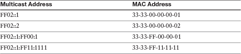
Recall that whenever a Layer 3 multicast packet is encapsulated into a Layer 2 Ethernet frame, the destination MAC address must be a group address. For IPv6 in particular, the group MAC address is computed using the prefix of 33-33 in hexadecimal, concatenated with the lowermost four bytes of the multicast IPv6 address, as shown in Table 11-1.
Now configure R8 to obtain its IPv6 address using SLAAC:
! On R8:
R8(config)# interface GigabitEthernet0/0
R8(config-if)# mac-address 0000.8888.8888
R8(config-if)# ipv6 enable
R8(config-if)# ipv6 address autoconfig default
R8(config-if)# no shutdown
Once the ipv6 enable and no shutdown commands are entered, R8 will automatically generate its link-local address (FE80::200:88FF:FE88:8888) and use Duplicate Address Detection (DAD) to ensure the uniqueness of this link-local IPv6 address. The additional ipv6 address autoconfig default command tells R8 to also acquire a network prefix using SLAAC, and to install a default route automatically through neighboring routers discovered during SLAAC.
Let’s verify the configuration:
R8# show ipv6 interface brief GigabitEthernet0/0
GigabitEthernet0/0 [up/up]
FE80::200:88FF:FE88:8888
18::200:88FF:FE88:8888
R8# show ipv6 interface GigabitEthernet0/0
GigabitEthernet0/0 is up, line protocol is up
IPv6 is enabled, link-local address is FE80::200:88FF:FE88:8888
No Virtual link-local address(es):
Stateless address autoconfig enabled
Global unicast address(es):
18::200:88FF:FE88:8888, subnet is 18::/64 [EUI/CAL/PRE]
valid lifetime 2591856 preferred lifetime 604656
Joined group address(es):
FF02::1
FF02::FB → This Multicast address is used for mDNS
FF02::1:FF88:8888
MTU is 1500 bytes
ICMP error messages limited to one every 100 milliseconds
ICMP redirects are enabled
ICMP unreachables are sent
ND DAD is enabled, number of DAD attempts: 1
ND reachable time is 30000 milliseconds (using 30000)
ND NS retransmit interval is 1000 milliseconds
Default router is FE80::200:11FF:FE11:1111 on GigabitEthernet0/0
The next hop for the automatically added default route is the link-local IPv6 address of R1. The verification of this fact is left as an exercise for the reader.
Task 2
R4 should be configured as a DHCP server, and R5 should be configured as a DHCP client acquiring an IPv6 address from R4. R5 should also get its domain name (example.com) and the DNS server’s IPv6 address (2001:1111::1) from R4.
Let’s configure R4 as a DHCP server using the options stated in the task. To work as a DHCP server, unicast routing must be enabled:
! On R4:
R4(config)# ipv6 unicast-routing
R4(config)# ipv6 dhcp pool TST
The following specifies the address range to provide in the pool:
R4(config-dhcpv6)# address prefix 45::/64
The following configuration provides the DNS server and the domain name option to DHCP clients:
R4(config-dhcpv6)# dns-server 2001:1:1111::1
R4(config-dhcpv6)# domain-name example.com
Let’s view the configuration of R4’s s1/5 interface:
R4# show run interface Serial 1/5 | begin interface
interface Serial1/5
no ip address
ipv6 address 45::4/64
ipv6 enable
clock rate 64000
end
The following command associates the DHCP pool with the interface facing the client (R5), effectively starting the particular DHCP server instance on s1/5:
R4(config)# interface Serial 1/5
R4(config-if)# no ipv6 nd ra suppress
R4(config-if)# ipv6 dhcp server TST
Serial interfaces do not send the Router Advertisement messages by default—this is different from Ethernet interfaces, where RA messages are sent automatically. Because they will be required later, we are configuring the s1/5 interface to send them.
As opposed to IPv4, where starting a DHCP server was essentially enough for the hosts to obtain their configuration via DHCP, in IPv6, the hosts must actually be instructed to use DHCP. Without this indication, they will continue using SLAAC. This is accomplished using the Router Advertisement (RA) messages.
RA messages contain two specific bits, or flags, that are used to inform hosts about the mechanism hosts should use to obtain their IPv6 settings. These flags are commonly called the M-flag and the O-flag.
The M-flag, or the managed address configuration flag, tells hosts to obtain their entire IPv6 configuration using DHCP, including their address, prefix length, DNS server address, domain name, and so on. The only parameter that will still remain discovered using RA messages is the default gateway address. DHCP for IPv6 does not support conveying the default gateway address information to clients because this information can always be learned from RA messages, which must have been received by hosts in the first place; otherwise, they would not be contacting DHCP at all. The M-flag can be set in outgoing RA messages using the ipv6 nd managed-config-flag interface configuration command.
The O-flag, or the other configuration flag, tells hosts to obtain their IPv6 address and gateway using SLAAC, and to acquire all other configuration (DNS address, domain name, and so on) using DHCP. The O-flag can be set in outgoing RA messages using the ipv6 nd other-config-flag interface configuration command.
It is important to note that these flags are indications only. It is entirely up to the software running on the host to honor them. Some operating systems may choose to ignore these flags and behave according to their preset configuration. This is also valid for IOS—obviously, when an interface is statically configured to obtain its configuration via DHCP, it will attempt to talk to DHCP even if the RA messages do not have the M-flag set. Nonetheless, we will set up the flags diligently—it is considered a best practice, as well as a very safe approach, to accommodate most operating systems.
The following command sets the M-flag in the RA messages. This tells the hosts not to rely on SLAAC and instead to use DHCP to obtain their IPv6 configuration. (Without this command, some hosts would continue using SLAAC even if the DHCP server was running.)
R4(config-if)# ipv6 nd managed-config-flag
Let’s enable debug ipv6 dhcp on R5:
! On R5:
R5# debug ipv6 dhcp
IPv6 DHCP debugging is on
Before configuring R5, let’s view the existing configuration of R5’s s1/4 interface:
interface Serial1/4
no ip address
shutdown
end
R5(config)# interface Serial 1/4
R5(config-if)# ipv6 enable
R5(config-if)# ipv6 address dhcp
R5(config-if)# no shutdown
Here, the ipv6 enable command is required to allow the interface to have a link-local address. Without it, the interface would be unable to send DHCP requests because it would have no source IPv6 address. Based on the following output, we can see that the local router (R5) sends a Solicit message to FF02::1:2. Because there is no broadcast in IPv6, this is a special multicast address that the clients use to communicate with a DHCP server.
The local router receives an Advertise message from the link-local IPv6 address of R4, the DHCP server.
The local router then sends a request to use the IPv6 address given to it by the DHCP server, and it receives a reply from the server. In IPv4 DHCP, we also had four messages: Discover, Offer, Request, and Acknowledge, all with a similar meaning.
IPv6 DHCP: Sending SOLICIT to FF02::1:2 on Serial1/4
IPv6 DHCP: Received ADVERTISE from FE80::217:59FF:FECE:2B8 on Serial1/4
IPv6 DHCP: Adding server FE80::217:59FF:FECE:2B8
IPv6 DHCP: Sending REQUEST to FF02::1:2 on Serial1/4
IPv6 DHCP: DHCPv6 address changes state from SOLICIT to REQUEST (ADDR_ADVERTISE_RECEIVED) on Serial1/4
IPv6 DHCP: Received REPLY from FE80::217:59FF:FECE:2B8 on Serial1/4
IPv6 DHCP: Processing options
IPv6 DHCP: Adding address 45::A58D:F28F:9901:DA14/128 to Serial1/4
IPv6 DHCP: T1 set to expire in 43200 seconds
IPv6 DHCP: T2 set to expire in 69120 seconds
IPv6 DHCP: Configuring DNS server 2001:1:1111::1
IPv6 DHCP: Configuring domain name example.com
IPv6 DHCP: DHCPv6 address changes state from REQUEST to OPEN (ADDR_REPLY_RECEIVED) on Serial1/4
Let’s verify the configuration:
! On R5:
R5# show ipv6 interface brief Serial 1/4
Serial1/4 [up/up]
FE80::21B:D4FF:FEBE:69D0
45::A58D:F28F:9901:DA14
You can see that the local router acquired an IPv6 address from the DHCP server. How do we display the DHCP optional parameters that the local router acquired from the DHCP server?
R5# show ipv6 dhcp interface
Serial1/4 is in client mode
Prefix State is IDLE
Address State is OPEN
Renew for address will be sent in 10:35:25
List of known servers:
Reachable via address: FE80::217:59FF:FECE:2B8
DUID: 00030001001759CE02B8
Preference: 0
Configuration parameters:
IA NA: IA ID 0x00090001, T1 43200, T2 69120
Address: 45::A58D:F28F:9901:DA14/128
preferred lifetime 86400, valid lifetime 172800
expires at Jul 07 2016 07:58 PM (167726 seconds)
DNS server: 2001:1:1111::1
Domain name: example.com
Information refresh time: 0
Prefix Rapid-Commit: disabled
Address Rapid-Commit: disabled
Rapid commit will be discussed and experimented with later in this chapter. We can continue our verification by looking at the ipv6 binding database on R4, the DHCP server, and comparing it to the IPv6 address assigned to R5’s Serial1/4 interface.
! On R4:
R4# show ipv6 dhcp binding
Client: FE80::21B:D4FF:FEBE:69D0
DUID: 00030001001BD4BE69D0
Username : unassigned
IA NA: IA ID 0x00090001, T1 43200, T2 69120
Address: 45::A58D:F28F:9901:DA14
preferred lifetime 86400, valid lifetime 172800
expires at Jul 07 2016 08:24 PM (167588 seconds)
R5# show ipv6 interface brief Serial1/4
Serial1/4 [up/up]
FE80::21B:D4FF:FEBE:69D0
45::A58D:F28F:9901:DA14
Even though not shown here, the show ipv6 route command would be somewhat disappointing because no default route would be installed.
The default route in DHCPv6 environments is somewhat confusing. Because IPv6 routers are required to send RA messages, the creators of DHCPv6 decided not to have a default gateway option for DHCPv6, and instead simply rely on the hosts discovering their gateways using RA messages. As a result, even in a DHCPv6 environment, RA messages are required for hosts to discover their gateway, while DHCPv6 provides the rest of the IPv6 configuration.
On Cisco IOS-based routers, having a router obtain its interface configuration through ipv6 address dhcp will cause it to obtain its address and other optional information via DHCP, but this will not make it install a default route through a neighbor sourcing RA messages. If you want to do that as well, you must add the ipv6 address autoconfig default command to the same interface to have the router install a default route discovered via SLAAC.
Finally, having an interface configured both with ipv6 address dhcp and ipv6 address autoconfig default will cause the interface to have two addresses: one obtained via DHCP, the other via SLAAC. Although this may appear to defeat the purpose of DHCP, that is not entirely true: You can configure R4’s s1/5 interface with the ipv6 nd prefix default no-advertise command, which will prevent R4 from advertising any prefix in its RA messages. Although R4 will continue to send RAs, there will be no global prefix advertised, so R5 would only install a default route through R4 without generating a SLAAC-derived address itself.
Task 3
R2 should be configured to acquire an IPv6 address from the DHCP server. R2 should acquire the following from the DHCP server (R4):
![]() An address from the range 12::/64
An address from the range 12::/64
![]() DNS server: 2000:2222::2
DNS server: 2000:2222::2
![]() Domain name: example.com
Domain name: example.com
R1 should be configured as a DHCP relay agent.
Let’s verify the configuration of R4’s s1/1 interface before adding additional configuration:
! On R4:
R4# show run interface Serial 1/1 | begin interface
interface Serial1/1
no ip address
ipv6 address 14::4/64
ipv6 enable
end
R4# ping 14::1
Type escape sequence to abort.
Sending 5, 100-byte ICMP Echos to 14::1, timeout is 2 seconds:
!!!!!
Success rate is 100 percent (5/5), round-trip min/avg/max = 28/28/28 ms
Let’s configure the DHCP server on R4 for the network where R2 resides:
R4(config)# ipv6 dhcp pool R2
R4(config-dhcpv6)# address prefix 12::/64
R4(config-dhcpv6)# dns-server 2000:2222::2
R4(config-dhcpv6)# domain-name example.com
Let’s apply the pool called “R2” to the closest interface toward R2:
R4(config)# interface Serial 1/1
R4(config-if)# ipv6 dhcp server R2
Let’s move to R1:
! On R1:
R1# show run interface Serial 1/2 | begin interface
interface Serial1/2
no ip address
ipv6 address 12::1/64
ipv6 enable
clock rate 64000
end
R1’s s1/2 interface should be configured to set the M-flag and then relay the Solicit messages to the DHCP server:
R1(config)# interface Serial 1/2
The following command configures the IPv6 address of the DHCP server by using the destination keyword; the reference to s1/4 as an outgoing interface is optional in this scenario. Referencing the outgoing interface would be required if the destination keyword pointed to the link-local IPv6 address of R4.
R1(config-if)# ipv6 dhcp relay destination 14::4 serial1/4
R1(config-if)# ipv6 nd managed-config-flag
R1(config-if)# no ipv6 nd ra suppress
As an aside, the configuration of IPv6 DHCP relay is much more intuitive than its IPv4 counterpart whose command, ip helper-address, does not even readily resemble anything related to DHCP.
In this case, R2 is going to be the DHCP client. R2 will multicast a DHCP Solicit message. R1 will receive this message and relay it to R4, the DHCP server. The Solicit message will have the Link Address field populated with the IPv6 address of R1’s link facing R2. R4 will go through its DHCP scopes and will find one that matches the same network. Subsequently, it will lease out an IPv6 address from that scope and offer it to R2 using the Advertise message. Note, however, that the Advertise response will be unicast to R1’s address learned from the Solicit message.
R1 will receive the Advertise message and will relay it down to R2. After R2 receives the Advertise message, it will continue with multicasting a DHCP Request message, which will again be relayed by R2 to R4. Then, R4 will respond with a DHCP Reply message to R2, which in turn forwards it to R1. At this point, R1 has a usable address. The entire process is very similar to IPv4 DHCP.
Note If the address prefix 12::/64 is configured in the previous pool (TST), R2 will get two IPv6 addresses: one from the 12::/64 network, and the second from the 45::/64 network. A DHCP pool in IPv6 can contain multiple IPv6 prefixes at the same time.
Let’s now configure the DHCP client on R2:
! On R2:
R2# show run interface Serial1/1 | begin interface
interface Serial1/1
no ip address
shutdown
end
R2(config)# interface Serial 1/1
R2(config-if)# ipv6 enable
R2(config-if)# ipv6 address dhcp
R2(config-if)# no shutdown
Now let’s verify the configuration:
! On R2:
R2# show ipv6 interface brief Serial 1/1
Serial1/1 [up/up]
FE80::21C:58FF:FEB9:F778
12::8C35:DAD7:B0C2:10BD
R2# show ipv6 dhcp interface
Serial1/1 is in client mode
Prefix State is IDLE
Address State is OPEN
Renew for address will be sent in 11:58:21
List of known servers:
Reachable via address: FE80::FEFB:FBFF:FEA1:1520
DUID: 00030001001759CE02B8
Preference: 0
Configuration parameters:
IA NA: IA ID 0x00060001, T1 43200, T2 69120
Address: 12::8C35:DAD7:B0C2:10BD/128
preferred lifetime 86400, valid lifetime 172800
expires at Jul 08 2016 04:15 AM (172701 seconds)
DNS server: 2000:2222::2
Domain name: example.com
Information refresh time: 0
Prefix Rapid-Commit: disabled
Address Rapid-Commit: disabled
Task 4
Reconfigure R5 to acquire its IPv6 address from R4 (the DHCP server) using two messages instead of four.
The DHCPv6 client can acquire its IPv6 address and optional parameters from a DHCP server in two ways:
![]() Rapid-commit: In this process, only two messages are exchanged: a Solicit from the client to the server, and a Reply from the server to the client.
Rapid-commit: In this process, only two messages are exchanged: a Solicit from the client to the server, and a Reply from the server to the client.
![]() Default: The DHCP client and server exchange four DHCP messages: Solicit, Advertise, Request, and Reply.
Default: The DHCP client and server exchange four DHCP messages: Solicit, Advertise, Request, and Reply.
Before the task is configured, let’s enable debug ipv6 dhcp, reset the s1/4 interface on R5 to the default configuration, and then set up the rapid-commit feature:
! On R5:
R5(config)# default interface Serial 1/4
Interface Serial1/4 set to default configuration
R5# debug ipv6 dhcp
IPv6 DHCP debugging is on
R5(config)# interface Serial 1/4
R5(config-if)# shutdown
R5(config-if)# ipv6 enable
R5(config-if)# ipv6 address dhcp rapid-commit
The rapid-commit option must be configured both on the DHCP client and the DHCP server to be effective. Here’s how to configure the DHCP server for rapid-commit:
! On R4:
R4(config)# interface Serial 1/5
R4(config-if)# shutdown
R4(config-if)# ipv6 dhcp server TST rapid-commit
R4(config-if)# no shutdown
! On R5:
R5(config-if)# interface Serial 1/4
R5(config-if)# no shutdown
Let’s verify the output of the debug command:
IPv6 DHCP: Sending SOLICIT to FF02::1:2 on Serial1/4
IPv6 DHCP: Received REPLY from FE80::217:59FF:FECE:2B8 on Serial1/4
IPv6 DHCP: Adding server FE80::217:59FF:FECE:2B8
IPv6 DHCP: Processing options
IPv6 DHCP: Adding address 45::A58D:F28F:9901:DA14/128 to Serial1/4
IPv6 DHCP: T1 set to expire in 43200 seconds
IPv6 DHCP: T2 set to expire in 69120 seconds
IPv6 DHCP: Configuring DNS server 2001:1:1111::1
IPv6 DHCP: Configuring domain name example.com
As you can see, only two messages were exchanged.
Task 5
ISP-A (represented by R4) has an IPv6 prefix of 46:1:1::/48, and it needs to automatically subnet this prefix into /56 subnets for its existing and future clients as well as assign the entire resulting /56 prefixes to the customers dynamically.
Company A (represented by R6) should acquire a /56 prefix from the ISP-A (R4) and automatically subnet this prefix into /64 subnetworks. The third subnet should be automatically assigned to its s1/3 interface, with the host portion of its IPv6 address as ::33. The seventh subnet should be automatically assigned to its F0/1 interface, with the host portion of its IPv6 address as ::77.
R3 and R7 should automatically acquire the network portion of their IPv6 addresses from R6 as well as auto-generate the host portion of their IPv6 addresses using the Modified EUI-64 format. Also, R3 and R7 should use R6 as their default gateway. Both R3 and R7 should have reachability to R4’s F0/0 IPv6 address.
Do not configure any static routes, dynamic routing, or complete static IPv6 addresses to accomplish this task.
Figure 11-3 shows the bits used by the provider to generate /56 subnets. When a customer requests a prefix, it is given one of these /56 subnets on a first-come-first-serve basis.
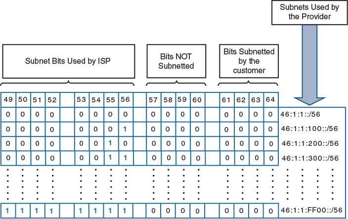
Figure 11-3 Provider Bits Used to Generate /56 Subnets
Figure 11-4 shows the bits that are given to the customer. The customer can use the remaining bits to generate up to 256 networks.
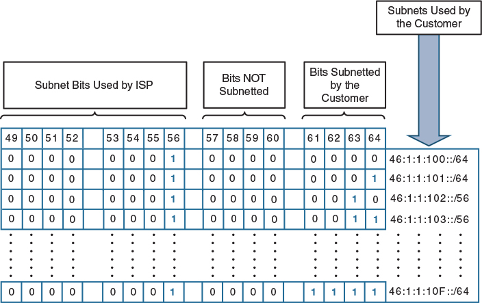
Figure 11-4 Bits Provided to the Customer
To resolve this task, you need to configure a DHCP feature called prefix delegation. The purpose of the prefix delegation mechanism is to delegate entire prefixes (not just individual address from within a prefix) to customer routers automatically. A prefix delegated to a customer can then be freely subnetted by the customer according to their needs.
In this topology, R4 is the delegating router. Let’s see the existing configuration of R4’s f0/0 interface:
! On R4:
R4# show run interface FastEthernet 0/0 | begin interface
interface FastEthernet0/0
no ip address
duplex auto
speed auto
ipv6 address FE80::4 link-local
ipv6 address 46::4/64
ipv6 enable
end
In order to accomplish this task, you need to configure a local pool that instructs the router to hand out /56 prefixes from the 46:1:1::/48 range:
! On R4:
R4(config)# ipv6 local pool 123 46:1:1::/48 56
Let’s verify the configuration:
R4# show ipv6 local pool
Pool Prefix Free In use
123 46:1:1::/48 256 0
Next, you need to configure a regular DHCPv6 pool called “ISP.” The DHCP pool will reference the local pool called “123” and assign a lifetime of infinity to every prefix leased from the pool.
The name of the DHCP pool can be anything (in this case, “ISP” is used).
R4(config)# ipv6 dhcp pool ISP
R4(config-dhcpv6)# prefix-delegation pool 123 lifetime infinite infinite
Assign the pool to the f0/0 interface of R4 facing R6:
R4(config)# interface FastEthernet 0/0
R4(config-if)# ipv6 dhcp server ISP
Next, R6 will act as the typical CPE (customer premises equipment) router. Its f0/0 interface will be considered a wide area network (WAN) interface for this exercise. R6 will acquire its IPv6 interface on f0/0 using SLAAC:
! On R6:
R6(config)# ipv6 unicast-routing
R6(config)# interface FastEthernet 0/0
R6(config-if)# ipv6 enable
R6(config-if)# ipv6 address autoconfig default
R6(config-if)# no shutdown
Let’s verify the configuration:
R6# show ipv6 interface brief FastEthernet 0/0
FastEthernet0/0 [up/up]
FE80::217:5AFF:FEAD:52AA
46::217:5AFF:FEAD:52AA
Next, the ipv6 dhcp client pd command enables R6 to ask for a delegated prefix using DHCP and to store the assigned prefix under a tag (or a variable) named TST. Later on, we will refer to TST to use the assigned prefix and subnet it further.
R6(config)# interface Fast Ethernet 0/0
R6(config-if)# ipv6 dhcp client pd TST
Let’s verify the configuration:
R6# show ipv6 dhcp interface
FastEthernet0/0 is in client mode
Prefix State is OPEN
Renew will be sent in 3d11h
Address State is IDLE
List of known servers:
Reachable via address: FE80::4
DUID: 00030001001759CE02B8
Preference: 0
Configuration parameters:
IA PD: IA ID 0x00030001, T1 302400, T2 483840
Prefix: 46:1:1::/56
preferred lifetime INFINITY, valid lifetime INFINITY
Information refresh time: 0
Prefix name: TST
Prefix Rapid-Commit: disabled
Address Rapid-Commit: disabled
You can see that prefix 46:1:1::/56 is given to R6, the Customer Edge (CE) device. Let’s configure the f0/1 and s1/3 interfaces of R6:
R6(config)# interface FastEthernet 0/1
R6(config-if)# ipv6 enable
The following example shows how to enable IPv6 processing on the interface and configure an address based on the prefix tag. In the ipv6 address command, you refer to TST as the name of the variable that stores the actual assigned prefix, and then specify the remainder of the address that should be appended to the prefix stored under TST. Note that the value of TST undergoes an OR operation and demonstrates the specified remainder, and that the remainder has to be 128 bits long, obviously having leading zeros in the part that will be copied from TST. That is the reason for the double-colon at the beginning of the address remainder. Note that ::7:… is the seventh subnet, meaning that you are assigning the seventh subnet to this interface; if you wanted to assign the second subnet, for example, you would use ::2:… instead.
R6(config-if)# ipv6 address TST ::7:0:0:0:77/64
R6(config-if)# no shutdown
Let’s verify the configuration:
R6# show ipv6 inter brief FastEthernet 0/1
FastEthernet0/1 [up/up]
FE80::217:5AFF:FEAD:52AB
46:1:1:7::77
R6# show ipv6 interface FastEthernet 0/1 | include subnet
46:1:1:7::77, subnet is 46:1:1:7::/64
R6# ping 46::4
Type escape sequence to abort.
Sending 5, 100-byte ICMP Echos to 46::4, timeout is 2 seconds:
!!!!!
Success rate is 100 percent (5/5), round-trip min/avg/max = 28/28/28 ms
Because R6 is a SLAAC client, it should get a default route from R4. Let’s verify this information:
R6# show ipv6 route static
IPv6 Routing Table - default - 7 entries
Codes: C - Connected, L - Local, S - Static, U - Per-user Static route
B - BGP, HA - Home Agent, MR - Mobile Router, R - RIP
I1 - ISIS L1, I2 - ISIS L2, IA - ISIS interarea, IS - ISIS summary
D - EIGRP, EX - EIGRP external, NM - NEMO, ND - Neighbor Discovery
l - LISP
O - OSPF Intra, OI - OSPF Inter, OE1 - OSPF ext 1, OE2 - OSPF ext 2
ON1 - OSPF NSSA ext 1, ON2 - OSPF NSSA ext 2
S ::/0 [2/0]
via FE80::4, FastEthernet0/0
S 46:1:1::/56 [1/0]
via Null0, directly connected
Let’s configure the s1/3 interface of R6:
R6(config)# interface Serial 1/3
R6(config-if)# ipv6 enable
R6(config-if)# ipv6 address TST ::3:0:0:0:33/64
R6(config-if)# no shutdown
To verify the configuration:
R6# show ipv6 interface Serial 1/3 | include subnet
46:1:1:3::33, subnet is 46:1:1:3::/64
Let’s configure R7 and R3 as a SLAAC client to R6:
! On R7:
R7(config)# interface GigabitEthernet 0/1
R7(config-if)# ipv6 enable
R7(config-if)# ipv6 address autoconfig default
R7(config-if)# no shutdown
Let’s verify the configuration:
R7# show ipv6 interface brief GigabitEthernet 0/1
GigabitEthernet0/1 [up/up]
FE80::26E9:B3FF:FEAB:4B21
46:1:1:7:26E9:B3FF:FEAB:4B21
! On R3:
R3(config)# interface Serial 1/6
R3(config-if)# clock rate 64000
R3(config-if)# ipv6 enable
R3(config-if)# ipv6 address autoconfig default
R3(config-if)# no shutdown
Let’s take a closer look at the ipv6 address that is assigned to R7’s Serial1/6 interface.
! On R3:
R7# show ipv6 interface brief Serial 1/6
Serial1/6 [up/up]
FE80::21C:58FF:FEF6:F660
46:1:1:3:21C:58FF:FEF6:F660
You can see that R7 has two injected routes, both injected via SLAAC: the first one is the default route, and the second is the global address prefix.
! On R7:
R7# show ipv6 route
IPv6 Routing Table - default - 4 entries
Codes: C - Connected, L - Local, S - Static, U - Per-user Static route
B - BGP, HA - Home Agent, MR - Mobile Router, R - RIP
H - NHRP, I1 - ISIS L1, I2 - ISIS L2, IA - ISIS interarea
IS - ISIS summary, D - EIGRP, EX - EIGRP external, NM - NEMO
ND - ND Default, NDp - ND Prefix, DCE - Destination, NDr - Redirect
O - OSPF Intra, OI - OSPF Inter, OE1 - OSPF ext 1, OE2 - OSPF ext 2
ON1 - OSPF NSSA ext 1, ON2 - OSPF NSSA ext 2, ls - LISP site
ld - LISP dyn-EID, a - Application
ND ::/0 [2/0]
via FE80::217:5AFF:FEAD:52AB, GigabitEthernet0/1
NDp 46:1:1:7::/64 [2/0]
via GigabitEthernet0/1, directly connected
L 46:1:1:7:26E9:B3FF:FEAB:4B21/128 [0/0]
via GigabitEthernet0/1, receive
L FF00::/8 [0/0]
via Null0, receive
R7# ping 46::4
Type escape sequence to abort.
Sending 5, 100-byte ICMP Echos to 46::4, timeout is 2 seconds:
!!!!!
Success rate is 100 percent (5/5), round-trip min/avg/max = 1/3/12 ms
R7# ping 46:1:1:3:21C:58FF:FEF6:F660
Type escape sequence to abort.
Sending 5, 100-byte ICMP Echos to ping 46:1:1:3:21C:58FF:FEF6:F660, timeout is 2 seconds:
!!!!!
Success rate is 100 percent (5/5), round-trip min/avg/max = 28/28/32 ms
! On R3:
R3# show ipv6 inter brief serial1/6
Serial1/6 [up/up]
FE80::21C:58FF:FEF6:F660
46:1:1:3:21C:58FF:FEF6:F660
You can see that R3 has a default route that was given to it because of the SLAAC process. Note how different IOS versions display routes differently. Because R7 is running 15.4T, it shows the default route as ND and the connected route as NDp. R3 is running 15.1(4), and the ND and NDp designations are not there.
R3# show ipv6 route
IPv6 Routing Table - default - 4 entries
Codes: C - Connected, L - Local, S - Static, U - Per-user Static route
B - BGP, HA - Home Agent, MR - Mobile Router, R - RIP
I1 - ISIS L1, I2 - ISIS L2, IA - ISIS interarea, IS - ISIS summary
D - EIGRP, EX - EIGRP external, NM - NEMO, ND - Neighbor Discovery
l - LISP
O - OSPF Intra, OI - OSPF Inter, OE1 - OSPF ext 1, OE2 - OSPF ext 2
ON1 - OSPF NSSA ext 1, ON2 - OSPF NSSA ext 2
S ::/0 [2/0]
via FE80::217:5AFF:FEAD:52AA, Serial1/6
C 46:1:1:3::/64 [0/0]
via Serial1/6, directly connected
L 46:1:1:3:21C:58FF:FEF6:F660/128 [0/0]
via Serial1/6, receive
L FF00::/8 [0/0]
via Null0, receive
R3# ping 46::4
Type escape sequence to abort.
Sending 5, 100-byte ICMP Echos to 46::4, timeout is 2 seconds:
!!!!!
Success rate is 100 percent (5/5), round-trip min/avg/max = 28/29/32 ms
R3# ping 46:1:1:7:26E9:B3FF:FEAB:4B21
Type escape sequence to abort.
Sending 5, 100-byte ICMP Echos to 46:1:1:7:26E9:B3FF:FEAB:4B21, timeout is 2 seconds:
!!!!!
Success rate is 100 percent (5/5), round-trip min/avg/max = 28/28/32 ms
Erase the startup configuration of the routers and reload them before proceeding to the next lab.
Lab 11-2: Configuring OSPFv3
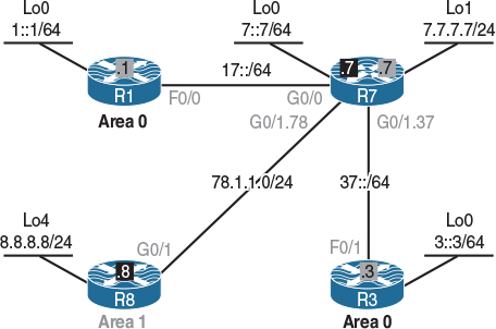
Figure 11-5 Configuring OSPFv3
Figure 11-5 illustrates the topology that will be used in the following lab.
Task 1
Configure OSPF and OSPFv3 on the routers in this topology based on the following policy:
![]() Configure the F0/0 interface of R1, the G0/0 interface of R7, and their loopback0 interfaces in Area 0.
Configure the F0/0 interface of R1, the G0/0 interface of R7, and their loopback0 interfaces in Area 0.
![]() Configure R8 and its loopback interface in Area 1.
Configure R8 and its loopback interface in Area 1.
![]() R7’s G0/1.78 should be configured in Area 1, and its G0/1.37 should be configured in Area 0.
R7’s G0/1.78 should be configured in Area 1, and its G0/1.37 should be configured in Area 0.
![]() R7 and R8 should accomplish this task using an address-family configuration section.
R7 and R8 should accomplish this task using an address-family configuration section.
![]() The loopback interface prefixes should be advertised with their correct mask.
The loopback interface prefixes should be advertised with their correct mask.
IPv6 unicast routing must be explicitly enabled before any routing protocol can be configured:
! On R1:
R1(config)# ipv6 unicast-routing
R1(config)# ipv6 router ospf 1
You should see the following console message stating that since OSPFv3 could not find an IPv4-configured interface, it could not assign a router ID. Let’s statically assign a router ID to this process:
%OSPFv3-4-NORTRID: OSPFv3 process 1 could not pick a router-id, please configure manually
R1(config-rtr)# router-id 0.0.0.1
R1(config)# interface loopback 0
R1(config-if)# ipv6 address 1::1/64
R1(config-if)# ipv6 ospf 1 area 0
R1(config)# interface FastEthernet0/0
R1(config-if)# ipv6 address 17::1/64
R1(config-if)# ipv6 ospf 1 area 0
Now let’s verify the configuration:
! On R1:
R1# show ipv6 ospf interface brief
Interface PID Area Intf ID Cost State Nbrs F/C
Lo0 1 0 22 1 LOOP 0/0
Fa0/0 1 0 3 1 DR 0/0
R1# show ipv6 ospf inter loopback 0
Loopback0 is up, line protocol is up
Link Local Address FE80::20A:B8FF:FE6B:DFD0, Interface ID 22
Area 0, Process ID 1, Instance ID 0, Router ID 0.0.0.1
Network Type LOOPBACK, Cost: 1
Loopback interface is treated as a stub Host
You can see that the loopback0 interface for R1 is treated as a host. This is the same behavior you know from OSPFv2. This will also cause any global address configured on the loopback0 interface to be advertised with a prefix length of 128 regardless of the true configured prefix length. Let’s therefore change the network type to point-to-point:
R1(config)# interface loopback 0
R1(config-if)# ipv6 ospf network point-to-point
Let’s verify the configuration:
! On R1:
R1# show ipv6 ospf interface loopback 0
Loopback0 is up, line protocol is up
Link Local Address FE80::20A:B8FF:FE6B:DFD0, Interface ID 22
Area 0, Process ID 1, Instance ID 0, Router ID 0.0.0.1
Network Type POINT_TO_POINT, Cost: 1
(The rest of the output is omitted for brevity)
OSPF on Cisco IOS-based routers can be configured in three ways: OSPFv2 configuration for IPv4 (router ospf), OSPFv3 configuration (ipv6 router ospf), and OSPFv3 using an address family (router ospfv3). The benefit of configuring OSPFv3 using the address family concept is that this configuration leverages the recently added OSPFv3 support to advertise both IPv4 and IPv6 prefixes, even though the transport always will be IPv6-based, and for each address family, OSPFv3 will start a separate instance.
! On R7:
R7(config)# ipv6 unicast-routing
The configuration starts with router ospfv3 followed by the process ID:
R7(config)# router ospfv3 1
The router ID is configured directly under address-family:
R7(config-router)# address-family ipv6 unicast
R7(config-router)# router-id 0.0.0.7
Running OSPFv3 on the interfaces is done by configuring ospfv3 followed by the process ID 1, followed by the ipv6 keyword to indicate that this instance is being started for IPv6. If this instance were intended for IPv4, the ipv4 keyword would be used instead. Finally, the area keyword is used to indicate the area.
R7(config)# interface loopback 0
R7(config-if)# ipv6 address 7::7/64
R7(config-if)# ospfv3 1 ipv6 area 0
R7(config-if)# ospfv3 network point-to-point
R7(config)# interface GigabitEthernet 0/0
R7(config-if)# ipv6 address 17::7/64
R7(config-if)# ospfv3 1 ipv6 area 0
You should see the following console message:
%OSPFv3-5-ADJCHG: Process 1, IPv6, Nbr 0.0.0.1 on GigabitEthernet0/0 from LOADING
to FULL, Loading Done
Let’s verify the configuration:
! On R7:
R7# show ipv6 route ospf
IPv6 Routing Table - default - 8 entries
Codes: C - Connected, L - Local, S - Static, U - Per-user Static route
B - BGP, HA - Home Agent, MR - Mobile Router, R - RIP
H - NHRP, I1 - ISIS L1, I2 - ISIS L2, IA - ISIS interarea
IS - ISIS summary, D - EIGRP, EX - EIGRP external, NM - NEMO
ND - ND Default, NDp - ND Prefix, DCE - Destination, NDr - Redirect
O - OSPF Intra, OI - OSPF Inter, OE1 - OSPF ext 1, OE2 - OSPF ext 2
ON1 - OSPF NSSA ext 1, ON2 - OSPF NSSA ext 2, ls - LISP site
ld - LISP dyn-EID, a - Application
O 1::/64 [110/2]
via FE80::1, GigabitEthernet0/0
R7# show ipv6 ospf neighbor
OSPFv3 Router with ID (0.0.0.7) (Process ID 1)
Neighbor ID Pri State Dead Time Interface ID Interface
0.0.0.1 1 FULL/DR 00:00:39 3 GigabitEthernet0/0
You can do the preceding show command using the following command:
R7# show ospfv3 neighbor
OSPFv3 1 address-family ipv6 (router-id 0.0.0.7)
Neighbor ID Pri State Dead Time Interface ID Interface
0.0.0.1 1 FULL/DR 00:00:32 3 GigabitEthernet0/0
Let’s configure OSPFv3 on the g0/1.37 interface:
R7(config)# interface GigabitEthernet0/1.37
R7(config-subif)# ipv6 address 37::7/64
R7(config-subif)# ospfv3 1 ipv6 area 0
Now you should configure R3 and verify its adjacency with R7:
! On R3:
R3(config)# ipv6 unicast-routing
R3(config)# ipv6 router ospf 1
R3(config-rtr)# router-id 0.0.0.3
R3(config)# interface FastEthernet 0/1
R3(config-if)# ipv6 address 37::3/64
R3(config-if)# ipv6 ospf 1 area 0
You should see the following console message:
%OSPFv3-5-ADJCHG: Process 1, Nbr 0.0.0.7 on FastEthernet0/1 from LOADING to FULL, Loading Done
R3(config-if)# interface loopback 0
R3(config-if)# ipv6 address 3::3/64
R3(config-if)# ipv6 ospf network point-to-point
R3(config-if)# ipv6 ospf 1 area 0
Let’s verify the configuration:
! On R3:
R3# show ipv6 route ospf
IPv6 Routing Table - default - 8 entries
Codes: C - Connected, L - Local, S - Static, U - Per-user Static route
B - BGP, HA - Home Agent, MR - Mobile Router, R - RIP
I1 - ISIS L1, I2 - ISIS L2, IA - ISIS interarea, IS - ISIS summary
D - EIGRP, EX - EIGRP external, NM - NEMO, ND - Neighbor Discovery
l - LISP
O - OSPF Intra, OI - OSPF Inter, OE1 - OSPF ext 1, OE2 - OSPF ext 2
ON1 - OSPF NSSA ext 1, ON2 - OSPF NSSA ext 2
O 1::/64 [110/3]
via FE80::7, FastEthernet0/1
O 7::/64 [110/2]
via FE80::7, FastEthernet0/1
O 17::/64 [110/2]
via FE80::7, FastEthernet0/1
R3# ping 7::7
Type escape sequence to abort.
Sending 5, 100-byte ICMP Echos to 7::7, timeout is 2 seconds:
!!!!!
Success rate is 100 percent (5/5), round-trip min/avg/max = 0/0/4 ms
R3# ping 7::7 source lo0
Type escape sequence to abort.
Sending 5, 100-byte ICMP Echos to 7::7, timeout is 2 seconds:
Packet sent with a source address of 3::3
!!!!!
Success rate is 100 percent (5/5), round-trip min/avg/max = 0/0/0 ms
Let’s configure OSPFv3 on R7 and R8 for IPv4:
! On R7:
R7(config)# router ospfv3 1
R7(config-router)# address-family ipv4 unicast
R7(config-router-af)# router-id 0.0.0.7
R7(config)# interface GigabitEthernet 0/1.78
R7(config-subif)# ip address 78.1.1.7 255.255.255.0
R7(config-subif)# ospfv3 1 ipv4 area 1
You should see the following console message:
% OSPFv3: IPV6 is not enabled on this interface
The reason you get this notification is that even though you are forming an OSPFv3 adjacency through the g0/1.78 subinterface, which should advertise IPv4 networks, OSPFv3 always uses IPv6 to exchange messages. To fix this problem, you need to enable IPv6 on this interface. This will allow the interface to have its own link-local address that is entirely sufficient to run OSPFv3.
R7(config-subif)# ipv6 enable
R7(config-subif)# ospfv3 1 ipv4 area 1
R7(config)# interface loopback 1
R7(config-if)# ip address 7.7.7.7 255.255.255.0
R7(config-if)# ipv6 enable
R7(config-if)# ospfv3 1 ipv4 area 1
R7(config-if)# ospfv3 network point-to-point
Now let’s configure R8:
! On R8:
R8(config)# router ospfv3 1
You should see the following console message:
%OSPFv3: IPv6 routing not enabled
Note The preceding console message states that ipv6 unicast-routing must be enabled in order for you to configure OSPFv3.
Let’s enable IPv6 unicast routing:
R8(config)# ipv6 unicast-routing
R8(config)# router ospfv3 1
R8(config-router)# address-family ipv4 unicast
R8(config-router-af)# router-id 0.0.0.8
R8(config)# interface GigabitEthernet 0/1
R8(config-if)# ip address 78.1.1.8 255.255.255.0
R8(config-if)# ipv6 enable
R8(config-if)# ospfv3 1 ipv4 area 1
R8(config)# interface loopback 0
R8(config-if)# ip address 8.8.8.8 255.255.255.0
R8(config-if)# ipv6 enable
R8(config-if)# ospfv3 1 ipv4 area 1
You should see the following console message:
%OSPFv3-5-ADJCHG: Process 1, IPv4, Nbr 0.0.0.7 on GigabitEthernet0/1 from LOADING
to FULL, Loading Done
Let’s verify the configuration:
! On R7:
R7# show ipv6 route ospf
IPv6 Routing Table - default - 9 entries
Codes: C - Connected, L - Local, S - Static, U - Per-user Static route
B - BGP, HA - Home Agent, MR - Mobile Router, R - RIP
H - NHRP, I1 - ISIS L1, I2 - ISIS L2, IA - ISIS interarea
IS - ISIS summary, D - EIGRP, EX - EIGRP external, NM - NEMO
ND - ND Default, NDp - ND Prefix, DCE - Destination, NDr - Redirect
O - OSPF Intra, OI - OSPF Inter, OE1 - OSPF ext 1, OE2 - OSPF ext 2
ON1 - OSPF NSSA ext 1, ON2 - OSPF NSSA ext 2, ls - LISP site
ld - LISP dyn-EID, a - Application
O 1::/64 [110/2]
via FE80::1, GigabitEthernet0/0
O 3::/64 [110/2]
via FE80::3, GigabitEthernet0/1.37
R7# show ip route ospfv3 | begin Gate
Gateway of last resort is not set
8.0.0.0/32 is subnetted, 1 subnets
O 8.8.8.8 [110/1] via 78.1.1.8, 00:03:48, GigabitEthernet0/1.78
You can see that loopback0 on R8 is not advertised with its correct mask. Let’s change the network type and verify:
Note The ip ospf network point-to-point command will not work because that is an OSPFv2 command. Because we have configured OSPFv3, the OSPFv3 command should be used to accomplish this task.
! On R8:
R8(config)# interface loopback 0
R8(config-if)# ospfv3 network point-to-point
! On R7:
R7# show ip route ospfv3 | begin Gate
Gateway of last resort is not set
8.0.0.0/24 is subnetted, 1 subnets
O 8.8.8.0 [110/2] via 78.1.1.8, 00:00:23, GigabitEthernet0/1.78
Erase the startup configuration of the routers and reload before proceeding to the next lab.
Lab 11-3: Summarization of Internal and External Networks
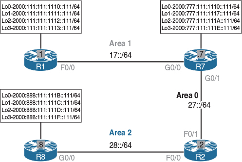
Figure 11-6 Summarization of Internal and External Networks
Figure 11-6 illustrates the topology that will be used in the following lab.
Task 1
Configure OSPFv3 based on the following requirements:
![]() Configure OSPFv3 on R1 and run all its directly connected interfaces in Area 1. Do not use address-family to configure this router. Configure and advertise the loopback interfaces with their correct mask. The RID of this router should be set to 0.0.0.1.
Configure OSPFv3 on R1 and run all its directly connected interfaces in Area 1. Do not use address-family to configure this router. Configure and advertise the loopback interfaces with their correct mask. The RID of this router should be set to 0.0.0.1.
![]() Configure OSPFv3 on R7 using address-family. This router should run OSPFv3 Area 1 on its G0/0 interface and OSPFv3 Area 0 on its G0/1 interface. The loopback interfaces of this router should be configured in Area 0. Configure and advertise the loopback interfaces with their correct mask. The RID of this router should be set to 0.0.0.7.
Configure OSPFv3 on R7 using address-family. This router should run OSPFv3 Area 1 on its G0/0 interface and OSPFv3 Area 0 on its G0/1 interface. The loopback interfaces of this router should be configured in Area 0. Configure and advertise the loopback interfaces with their correct mask. The RID of this router should be set to 0.0.0.7.
![]() Configure OSPFv3 on R2 and run its F0/1 interface in Area 0 and its F0/0 interface in Area 2. Do not use address-family to configure this router. The RID of this router should be set to 0.0.0.2.
Configure OSPFv3 on R2 and run its F0/1 interface in Area 0 and its F0/0 interface in Area 2. Do not use address-family to configure this router. The RID of this router should be set to 0.0.0.2.
![]() Configure OSPFv3 on R8 using address-family. This router should run OSPFv3 Area 2 on its G0/0 interface. The loopback interfaces of this router should be injected into the OSPFv3 routing domain. The RID of this router should be set to 0.0.0.8.
Configure OSPFv3 on R8 using address-family. This router should run OSPFv3 Area 2 on its G0/0 interface. The loopback interfaces of this router should be injected into the OSPFv3 routing domain. The RID of this router should be set to 0.0.0.8.
! On R1:
R1(config)# ipv6 unicast-routing
R1(config)# ipv6 router ospf 1
R1(config-rtr)# router-id 0.0.0.1
R1(config)# interface FastEthernet 0/0
R1(config-if)# ipv6 address 17::1/64
R1(config-if)# ipv6 ospf 1 area 1
R1(config)# interface Loopback 0
R1(config-if)# ipv6 address 2000:111:111:1110::111/64
R1(config-if)# interface Loopback 1
R1(config-if)# ipv6 address 2000:111:111:1111::111/64
R1(config-if)# interface Loopback 2
R1(config-if)# ipv6 address 2000:111:111:1112::111/64
R1(config-if)# interface Loopback 3
R1(config-if)# ipv6 address 2000:111:111:1113::111/64
R1(config-if)# interface range Loopback 0 - 3
R1(config-if-range)# ipv6 ospf 1 area 1
R1(config-if-range)# ipv6 ospf network point-to-point
Let’s verify the configuration:
R1# show ipv6 ospf interface brief
Interface PID Area Intf ID Cost State Nbrs F/C
Lo1 1 1 23 1 P2P 0/0
Lo2 1 1 24 1 P2P 0/0
Lo3 1 1 25 1 P2P 0/0
Lo0 1 1 22 1 P2P 0/0
Fa0/0 1 1 3 1 DR 0/0
! On R7:
R7(config)# ipv6 unicast-routing
R7(config)# router ospfv3 1
R7(config-router)# address-family ipv6 unicast
R7(config-router-af)# router-id 0.0.0.7
R7(config)# interface GigabitEthernet 0/1
R7(config-if)# ipv6 address 27::7/64
R7(config-if)# ospfv3 1 ipv6 area 0
R7(config)# interface GigabitEthernet 0/0
R7(config-if)# ipv6 address 17::7/64
R7(config-if)# ospfv3 1 ipv6 area 1
You should see the following console message:
%OSPFv3-5-ADJCHG: Process 1, IPv6, Nbr 0.0.0.1 on GigabitEthernet0/0 from LOADING
to FULL, Loading Done
R7(config)# interface Loopback 0
R7(config-if)# ipv6 address 2000:777:111:1110::111/64
R7(config-if)# interface Loopback 1
R7(config-if)# ipv6 address 2000:777:111:1117::111/64
R7(config-if)# interface Loopback 2
R7(config-if)# ipv6 address 2000:777:111:111A::111/64
R7(config-if)# interface Loopback 3
R7(config-if)# ipv6 address 2000:777:111:111E::111/64
R7(config-if)# interface range Loopback 0 - 3
R7(config-if-range)# ospfv3 1 ipv6 area 0
R7(config-if-range)# ospfv3 network point-to-point
Let’s verify the configuration:
R7# show ospfv3 interface brief
Interface PID Area AF Cost State Nbrs F/C
Lo0 1 0 ipv6 1 P2P 0/0
Lo1 1 0 ipv6 1 P2P 0/0
Lo2 1 0 ipv6 1 P2P 0/0
Lo3 1 0 ipv6 1 P2P 0/0
Gi0/1 1 0 ipv6 1 DR 0/0
Gi0/0 1 1 ipv6 1 BDR 1/1
R7# show ipv6 route ospf
IPv6 Routing Table - default - 17 entries
Codes: C - Connected, L - Local, S - Static, U - Per-user Static route
B - BGP, HA - Home Agent, MR - Mobile Router, R - RIP
H - NHRP, I1 - ISIS L1, I2 - ISIS L2, IA - ISIS interarea
IS - ISIS summary, D - EIGRP, EX - EIGRP external, NM - NEMO
ND - ND Default, NDp - ND Prefix, DCE - Destination, NDr - Redirect
O - OSPF Intra, OI - OSPF Inter, OE1 - OSPF ext 1, OE2 - OSPF ext 2
ON1 - OSPF NSSA ext 1, ON2 - OSPF NSSA ext 2, ls - LISP site
ld - LISP dyn-EID, a - Application
O 2000:111:111:1110::/64 [110/2]
via FE80::1, GigabitEthernet0/0
O 2000:111:111:1111::/64 [110/2]
via FE80::1, GigabitEthernet0/0
O 2000:111:111:1112::/64 [110/2]
via FE80::1, GigabitEthernet0/0
O 2000:111:111:1113::/64 [110/2]
via FE80::1, GigabitEthernet0/0
R7# show ospfv3 neighbor
OSPFv3 1 address-family ipv6 (router-id 0.0.0.7)
Neighbor ID Pri State Dead Time Interface ID Interface
0.0.0.1 1 FULL/DR 00:00:37 3 GigabitEthernet0/0
! On R2:
R2(config)# ipv6 unicast-routing
R2(config)# ipv6 router ospf 1
R2(config-rtr)# router-id 0.0.0.2
R2(config)# interface FastEthernet 0/1
R2(config-if)# ipv6 address 27::2/64
R2(config-if)# ipv6 ospf 1 area 0
R2(config)# interface FastEthernet 0/0
R2(config-if)# ipv6 address 28::2/64
R2(config-if)# ipv6 ospf 1 area 2
You should see the following console message:
%OSPFv3-5-ADJCHG: Process 1, Nbr 0.0.0.7 on FastEthernet0/1 from LOADING to FULL, Loading Done
Let’s verify the configuration:
! On R2:
R2# show ipv6 route ospf
IPv6 Routing Table - default - 14 entries
Codes: C - Connected, L - Local, S - Static, U - Per-user Static route
B - BGP, HA - Home Agent, MR - Mobile Router, R - RIP
I1 - ISIS L1, I2 - ISIS L2, IA - ISIS interarea, IS - ISIS summary
D - EIGRP, EX - EIGRP external, NM - NEMO, ND - Neighbor Discovery
l - LISP
O - OSPF Intra, OI - OSPF Inter, OE1 - OSPF ext 1, OE2 - OSPF ext 2
ON1 - OSPF NSSA ext 1, ON2 - OSPF NSSA ext 2
OI 17::/64 [110/2]
via FE80::7, FastEthernet0/1
OI 2000:111:111:1110::/64 [110/3]
via FE80::7, FastEthernet0/1
OI 2000:111:111:1111::/64 [110/3]
via FE80::7, FastEthernet0/1
OI 2000:111:111:1112::/64 [110/3]
via FE80::7, FastEthernet0/1
OI 2000:111:111:1113::/64 [110/3]
via FE80::7, FastEthernet0/1
O 2000:111:111:1117::/64 [110/2]
via FE80::7, FastEthernet0/1
O 2000:111:111:111A::/64 [110/2]
via FE80::7, FastEthernet0/1
O 2000:111:111:111E::/64 [110/2]
via FE80::7, FastEthernet0/1
O 2000:777:111:1110::/64 [110/2]
via FE80::7, FastEthernet0/1
Because the task does not specify the area in which the loopback interfaces on R8 should be configured, the only other way to run them in OSPF is to redistribute them into the OSPF routing domain. Let’s configure R8 based on the requirements of this task:
! On R8:
R8(config)# ipv6 unicast-routing
R8(config)# interface Loopback 0
R8(config-if)# ipv6 address 2000:888:111:111B::111/64
R8(config-if)# interface Loopback 1
R8(config-if)# ipv6 address 2000:888:111:111C::111/64
R8(config-if)# interface Loopback 2
R8(config-if)# ipv6 address 2000:888:111:111D::111/64
R8(config-if)# interface Loopback 3
R8(config-if)# ipv6 address 2000:888:111:111F::111/64
R8(config)# interface GigabitEthernet 0/0
R8(config-if)# ipv6 address 28::8/64
R8(config-if)# ospfv3 1 ipv6 area 2
R8(config)# route-map tst
R8(config-route-map)# match interface lo0 lo1 lo2 lo3
R8(config)# router ospfv3 1
R8(config-router)# address-family ipv6 unicast
R8(config-router-af)# router-id 0.0.0.8
R8(config-router-af)# redistribute connected route-map tst
You should see the following console message:
%OSPFv3-5-ADJCHG: Process 1, IPv6, Nbr 0.0.0.2 on GigabitEthernet0/0 from LOADING
to FULL, Loading Done
Let’s verify the configuration:
! On R8:
R8# show ipv6 route ospf
IPv6 Routing Table - default - 21 entries
Codes: C - Connected, L - Local, S - Static, U - Per-user Static route
B - BGP, HA - Home Agent, MR - Mobile Router, R - RIP
H - NHRP, I1 - ISIS L1, I2 - ISIS L2, IA - ISIS interarea
IS - ISIS summary, D - EIGRP, EX - EIGRP external, NM - NEMO
ND - ND Default, NDp - ND Prefix, DCE - Destination, NDr - Redirect
O - OSPF Intra, OI - OSPF Inter, OE1 - OSPF ext 1, OE2 - OSPF ext 2
ON1 - OSPF NSSA ext 1, ON2 - OSPF NSSA ext 2, ls - LISP site
ld - LISP dyn-EID, a - Application
OI 17::/64 [110/3]
via FE80::2, GigabitEthernet0/0
OI 27::/64 [110/2]
via FE80::2, GigabitEthernet0/0
OI 2000:111:111:1110::/64 [110/4]
via FE80::2, GigabitEthernet0/0
OI 2000:111:111:1111::/64 [110/4]
via FE80::2, GigabitEthernet0/0
OI 2000:111:111:1112::/64 [110/4]
via FE80::2, GigabitEthernet0/0
OI 2000:111:111:1113::/64 [110/4]
via FE80::2, GigabitEthernet0/0
OI 2000:111:111:1117::/64 [110/3]
via FE80::2, GigabitEthernet0/0
OI 2000:111:111:111A::/64 [110/3]
via FE80::2, GigabitEthernet0/0
OI 2000:111:111:111E::/64 [110/3]
via FE80::2, GigabitEthernet0/0
OI 2000:777:111:1110::/64 [110/3]
via FE80::2, GigabitEthernet0/0
! On R1:
R1# show ipv6 route ospf
IPv6 Routing Table - default - 18 entries
Codes: C - Connected, L - Local, S - Static, U - Per-user Static route
B - BGP, HA - Home Agent, MR - Mobile Router, R - RIP
I1 - ISIS L1, I2 - ISIS L2, IA - ISIS interarea, IS - ISIS summary
D - EIGRP, EX - EIGRP external, NM - NEMO, ND - Neighbor Discovery
l - LISP
O - OSPF Intra, OI - OSPF Inter, OE1 - OSPF ext 1, OE2 - OSPF ext 2
ON1 - OSPF NSSA ext 1, ON2 - OSPF NSSA ext 2
OI 27::/64 [110/2]
via FE80::7, FastEthernet0/0
OI 28::/64 [110/3]
via FE80::7, FastEthernet0/0
OI 2000:111:111:1117::/64 [110/2]
via FE80::7, FastEthernet0/0
OI 2000:111:111:111A::/64 [110/2]
via FE80::7, FastEthernet0/0
OI 2000:111:111:111E::/64 [110/2]
via FE80::7, FastEthernet0/0
OI 2000:777:111:1110::/64 [110/2]
via FE80::7, FastEthernet0/0
OE2 2000:888:111:111B::/64 [110/20]
via FE80::7, FastEthernet0/0
OE2 2000:888:111:111C::/64 [110/20]
via FE80::7, FastEthernet0/0
OE2 2000:888:111:111D::/64 [110/20]
via FE80::7, FastEthernet0/0
OE2 2000:888:111:111F::/64 [110/20]
Task 2
Summarize the loopback interfaces configured on R1 and R7 in all OSPF areas. There should be a single summary route for the loopback interfaces of R1 and R7. Do not configure more than two different summary routes to accomplish this task.
In OSPF, summarization can be configured on an Area Border Router (ABR) and an Autonomous System Boundary Router (ASBR), and it’s applied either to all routes coming from a given area or to redistributed networks. Because R7 is the ABR between Areas 0 and 1, you should configure R7 to summarize the networks coming from R1 when advertising them to R2.
The process of summarization in IPv6 is identical to IPv4. Let’s look at the IPv6 addresses on R1:
Lo0: 2000:111:111:1110::111/64
Lo1: 2000:111:111:1111::111/64
Lo2: 2000:111:111:1112::111/64
Lo3: 2000:111:111:1113::111/64
You can see that they all start with 2000:111:111:111, but the last hex digit in the fourth hextet is where they differ. Let’s convert the last hex digit of the fourth hextet to binary (remember that every hex digit represents four bits):
0 = 0 0 0 0
1 = 0 0 0 1
2 = 0 0 1 0
3 = 0 0 1 1
Counting the common identical prefixing contiguous bits, you should see the following:
0 = 0 0 0 0
1 = 0 0 0 1
2 = 0 0 1 0
3 = 0 0 1 1
You can see that the last two binary digits is where these hex digits differ; therefore, all the bits up to the third binary digit of the fourth hextet are identical. In other words, these four addresses are common in their first 62 bits (16 : 16 : 16 : 14) and differ afterward. Therefore, the following statement summarizes these four networks:
2000:111:111:1110::/62
Let’s configure OSPFv3 to summarize these networks, but before we summarize, let’s verify the routing table of R7 and look for these networks:
! On R7:
R7# show ipv6 route ospf | include 2000:111:111
O 2000:111:111:1110::/64 [110/2]
O 2000:111:111:1111::/64 [110/2]
O 2000:111:111:1112::/64 [110/2]
O 2000:111:111:1113::/64 [110/2]
Let’s summarize:
R7(config)# router ospfv3 1
R7(config-router)# address-family ipv6 unicast
R7(config-router-af)# area 1 range 2000:111:111:1110::/62
Now let’s verify the configuration:
! On R2:
R2# show ipv6 route ospf | include 2000:111:111:1110
OI 2000:111:111:1110::/62 [110/3]
When routes are summarized in OSPFv2, a discard route is injected. Let’s verify whether the behavior is the same in OSPFv3:
! On R7:
R7# show ipv6 route ospf | include /62|Null
O 2000:111:111:1110::/62 [110/2]
via Null0, directly connected
You can see that the discard route is injected to avoid forwarding loops just like OSPFv2.
Let’s summarize the loopback interfaces configured on R7 as advertised from Area 0 into Area 1:
Lo0: 2000:777:111:1110::111/64
Lo1: 2000:777:111:1117::111/64
Lo2: 2000:777:111:111A::111/64
Lo3: 2000:777:111:111E::111/64
Once again, the last hex digit of the fourth hextet is where they differ, so let’s go through the same process:
0 = 0 0 0 0
7 = 0 1 1 1
A = 1 0 1 0
E = 1 1 1 0
In this case, these four values do not share any common bit prefix. If you wanted to be very precise, the four loopbacks on R7 cannot be correctly summarized because the networks do not constitute a contiguous address space at all. However, you can always configure a larger summary network that covers all loopback networks on R7, even if it also includes networks that do not exist on R7. This is necessary to meet the requirements of this task.
The four loopback addresses on R7 match in their first 16 : 16 : 16 : 12 bits, and looking at the matching bits, you see that the summary network is
2000:777:111:1110::/60
R7(config)# router ospfv3 1
R7(config-router)# address-family ipv6 unicast
R7(config-router-af)# area 0 range 2000:777:111:1110::/60
Let’s verify the configuration:
! On R1:
R1# show ipv6 route ospf | inc/60
OI 2000:777:111:1110::/60 [110/2]
R1# ping 2000:777:111:1117::111
Type escape sequence to abort.
Sending 5, 100-byte ICMP Echos to 2000:777:111:1117::111, timeout is 2 seconds:
!!!!!
Success rate is 100 percent (5/5), round-trip min/avg/max = 0/1/4 ms
You need to repeat the same configuration on R2 when advertising networks into Area 2, but before we configure the summary route for R7’s loopback interfaces, let’s verify the routing table of R8:
! On R8:
R8# show ipv6 route ospf
IPv6 Routing Table - default - 18 entries
Codes: C - Connected, L - Local, S - Static, U - Per-user Static route
B - BGP, HA - Home Agent, MR - Mobile Router, R - RIP
H - NHRP, I1 - ISIS L1, I2 - ISIS L2, IA - ISIS interarea
IS - ISIS summary, D - EIGRP, EX - EIGRP external, NM - NEMO
ND - ND Default, NDp - ND Prefix, DCE - Destination, NDr - Redirect
O - OSPF Intra, OI - OSPF Inter, OE1 - OSPF ext 1, OE2 - OSPF ext 2
ON1 - OSPF NSSA ext 1, ON2 - OSPF NSSA ext 2, ls - LISP site
ld - LISP dyn-EID, a – Application
OI 17::/64 [110/3]
via FE80::2, GigabitEthernet0/0
OI 27::/64 [110/2]
via FE80::2, GigabitEthernet0/0
OI 2000:111:111:1110::/62 [110/4]
via FE80::2, GigabitEthernet0/0
OI 2000:777:111:1110::/64 [110/3]
via FE80::2, GigabitEthernet0/0
OI 2000:777:111:1117::/64 [110/3]
via FE80::2, GigabitEthernet0/0
OI 2000:777:111:111A::/64 [110/3]
via FE80::2, GigabitEthernet0/0
OI 2000:777:111:111E::/64 [110/3]
via FE80::2, GigabitEthernet0/0
! On R2:
R2(config)# ipv6 router ospf 1
R2(config-rtr)# area 0 range 2000:777:111:1110::/60
Now let’s verify the configuration:
! On R8:
R8# show ipv6 route ospf
IPv6 Routing Table - default - 15 entries
Codes: C - Connected, L - Local, S - Static, U - Per-user Static route
B - BGP, HA - Home Agent, MR - Mobile Router, R - RIP
H - NHRP, I1 - ISIS L1, I2 - ISIS L2, IA - ISIS interarea
IS - ISIS summary, D - EIGRP, EX - EIGRP external, NM - NEMO
ND - ND Default, NDp - ND Prefix, DCE - Destination, NDr - Redirect
O - OSPF Intra, OI - OSPF Inter, OE1 - OSPF ext 1, OE2 - OSPF ext 2
ON1 - OSPF NSSA ext 1, ON2 - OSPF NSSA ext 2, ls - LISP site
ld - LISP dyn-EID, a - Application
OI 17::/64 [110/3]
via FE80::2, GigabitEthernet0/0
OI 27::/64 [110/2]
via FE80::2, GigabitEthernet0/0
OI 2000:111:111:1110::/62 [110/4]
via FE80::2, GigabitEthernet0/0
OI 2000:777:111:1110::/60 [110/3]
via FE80::2, GigabitEthernet0/0
R8# ping 2000:777:111:1117::111
Type escape sequence to abort.
Sending 5, 100-byte ICMP Echos to 2000:777:111:1117::111, timeout is 2 seconds:
!!!!!
Success rate is 100 percent (5/5), round-trip min/avg/max = 1/1/4 ms
Task 3
Summarize the external routes redistributed on R8. If this summarization is performed correctly, the rest of the routers should see a single summary route for the four networks redistributed into the OSPF routing domain.
Let’s look at the IPv6 addresses that you are going to summarize:
Lo0: 2000:888:111:111B::111/64
Lo1: 2000:888:111:111C::111/64
Lo2: 2000:888:111:111D::111/64
Lo3: 2000:888:111:111F::111/64
Let’s configure the last digit of the fourth hextet to binary:
B = 1 0 1 1
C = 1 1 0 0
D = 1 1 0 1
F = 1 1 1 1
You need to take a relaxed approach to summarizing these networks again. Note that the only leading bit common to these networks is the first one. Therefore, the summary route should be 2000:888:111:1118::/61. Let’s configure it and verify.
In OSPFv2, you use the area range command for internal routes and summary-address for summarizing external routes. In OSPFv3, you still use the area range command for internal routes, but for external routes, instead of the summary-address command, you use the summary-prefix command, like so:
! On R8:
R8(config)# router ospfv3 1
R8(config-router)# address-family ipv6 unicast
R8(config-router-af)# summary-prefix 2000:888:111:1118::/61
Let’s verify the configuration:
! On R1:
R1# show ipv6 route ospf | inc /61
OE2 2000:888:111:1118::/61 [110/20]
R1# ping 2000:888:111:111f::111
Type escape sequence to abort.
Sending 5, 100-byte ICMP Echos to 2000:888:111:111F::111, timeout is 2 seconds:
!!!!!
Success rate is 100 percent (5/5), round-trip min/avg/max = 0/0/4 ms
Task 4
The policy for summarizing external routes has changed. The routers in Area 2 should see all specific external routes, whereas the routers in the other areas should see a single summary route for the four external routes.
Let’s remove the summary-prefix command configured in the previous step:
! On R8:
R8(config)# router ospfv3 1
R8(config-router)# address-family ipv6 unicast
R8(config-router-af)# no summary-prefix 2000:888:111:1118::/61
Let’s verify the configuration:
! On R1:
R1# show ipv6 route ospf | inc /61
R1# show ipv6 route ospf | inc OE2
O - OSPF Intra, OI - OSPF Inter, OE1 - OSPF ext 1, OE2 - OSPF ext 2
OE2 2000:888:111:111B::/64 [110/20]
OE2 2000:888:111:111C::/64 [110/20]
OE2 2000:888:111:111D::/64 [110/20]
OE2 2000:888:111:111F::/64 [110/20]
Note Summarization in OSPFv3 is identical to that in OSPFv2. Summarization can be configured for two router types, depending on what routes are to be summarized:
![]() The routes are internal. If the routes are internal, the summarization can only be configured on the ABRs using the area range command.
The routes are internal. If the routes are internal, the summarization can only be configured on the ABRs using the area range command.
![]() The routes are external. There are two types of external routes: the “E” routes and the “N” routes. Both of them can only be summarized at ASBRs that originate them. The small trick here comes from the fact that when N routes are translated into E routes (also called 7-to-5 translation, because Type-7 LSAs are translated into Type-5 LSAs), the ABR performing the 7-to-5 translation effectively becomes an ASBR as well and is thus allowed to perform the summarization of translated external routes.
The routes are external. There are two types of external routes: the “E” routes and the “N” routes. Both of them can only be summarized at ASBRs that originate them. The small trick here comes from the fact that when N routes are translated into E routes (also called 7-to-5 translation, because Type-7 LSAs are translated into Type-5 LSAs), the ABR performing the 7-to-5 translation effectively becomes an ASBR as well and is thus allowed to perform the summarization of translated external routes.
Because the routers in Area 2 should see all the specific routes, and the routers in the other areas should only see a single summary route, Area 2 is converted into a Not-So-Stubby Area (NSSA). Once that happens, R2 will receive the N routes, and it will translate them into E routes. Because R2 is the one that originates the external E routes, it can summarize the routes redistributed by R8.
! On R8:
R8(config)# router ospfv3 1
R8(config-router)# address-family ipv6 unicast
R8(config-router-af)# area 2 nssa
You should see the following console message stating that the adjacency to R2 is down. This is because the area NSSA flag no longer matches. Once R2 is configured with area 2 nssa, the area NSSA flag will match and the adjacency will be reestablished.
%OSPFv3-5-ADJCHG: Process 1, IPv6, Nbr 0.0.0.2 on GigabitEthernet0/0 from FULL to
DOWN, Neighbor Down: Adjacency forced to reset
! On R2:
R2(config)# ipv6 router ospf 1
R2(config-rtr)# area 2 nssa
R2(config-rtr)# summary-prefix 2000:888:111:1118::/61
You should see the following console message stating that the adjacency with 0.0.0.8 or R8 is in the FULL state:
%OSPFv3-5-ADJCHG: Process 1, Nbr 0.0.0.8 on FastEthernet0/0 from LOADING to FULL,
Loading Done
Let’s verify the configuration:
! On R1:
R1# show ipv6 route ospf | inc/61
O - OSPF Intra, OI - OSPF Inter, OE1 - OSPF ext 1, OE2 - OSPF ext 2
OE2 2000:888:111:1118::/61 [110/20]
R1# ping 2000:888:111:111f::111
Type escape sequence to abort.
Sending 5, 100-byte ICMP Echos to 2000:888:111:111F::111, timeout is 2 seconds:
!!!!!
Success rate is 100 percent (5/5), round-trip min/avg/max = 0/1/4 ms
! On R2:
R2# show ipv6 route ospf
IPv6 Routing Table - default - 17 entries
Codes: C - Connected, L - Local, S - Static, U - Per-user Static route
B - BGP, HA - Home Agent, MR - Mobile Router, R - RIP
I1 - ISIS L1, I2 - ISIS L2, IA - ISIS interarea, IS - ISIS summary
D - EIGRP, EX - EIGRP external, NM - NEMO, ND - Neighbor Discovery
l - LISP
O - OSPF Intra, OI - OSPF Inter, OE1 - OSPF ext 1, OE2 - OSPF ext 2
ON1 - OSPF NSSA ext 1, ON2 - OSPF NSSA ext 2
OI 17::/64 [110/2]
via FE80::7, FastEthernet0/1
OI 2000:111:111:1110::/62 [110/3]
via FE80::7, FastEthernet0/1
O 2000:777:111:1110::/60 [110/0]
via Null0, directly connected
O 2000:777:111:1110::/64 [110/2]
via FE80::7, FastEthernet0/1
O 2000:777:111:1117::/64 [110/2]
via FE80::7, FastEthernet0/1
O 2000:777:111:111A::/64 [110/2]
via FE80::7, FastEthernet0/1
O 2000:777:111:111E::/64 [110/2]
via FE80::7, FastEthernet0/1
O 2000:888:111:1118::/61 [110/0]
via Null0, directly connected
ON2 2000:888:111:111B::/64 [110/20]
via 28::8, FastEthernet0/0
ON2 2000:888:111:111C::/64 [110/20]
via 28::8, FastEthernet0/0
ON2 2000:888:111:111D::/64 [110/20]
via 28::8, FastEthernet0/0
ON2 2000:888:111:111F::/64 [110/20]
via 28::8, FastEthernet0/0
Task 5
None of the routers should have a discard route in their routing table.
In OSPF, the discard routes are auto-injected on the router that performs summarization. Let’s verify the existence of the discard routes on R7 and R2:
! On R2:
R2# show ipv6 route ospf
IPv6 Routing Table - default - 17 entries
Codes: C - Connected, L - Local, S - Static, U - Per-user Static route
B - BGP, HA - Home Agent, MR - Mobile Router, R - RIP
I1 - ISIS L1, I2 - ISIS L2, IA - ISIS interarea, IS - ISIS summary
D - EIGRP, EX - EIGRP external, NM - NEMO, ND - Neighbor Discovery
l - LISP
O - OSPF Intra, OI - OSPF Inter, OE1 - OSPF ext 1, OE2 - OSPF ext 2
ON1 - OSPF NSSA ext 1, ON2 - OSPF NSSA ext 2
OI 17::/64 [110/2]
via FE80::7, FastEthernet0/1
OI 2000:111:111:1110::/62 [110/3]
via FE80::7, FastEthernet0/1
O 2000:777:111:1110::/60 [110/0]
via Null0, directly connected
O 2000:777:111:1110::/64 [110/2]
via FE80::7, FastEthernet0/1
O 2000:777:111:1117::/64 [110/2]
via FE80::7, FastEthernet0/1
O 2000:777:111:111A::/64 [110/2]
via FE80::7, FastEthernet0/1
O 2000:777:111:111E::/64 [110/2]
via FE80::7, FastEthernet0/1
O 2000:888:111:1118::/61 [110/0]
via Null0, directly connected
ON2 2000:888:111:111B::/64 [110/20]
via 28::8, FastEthernet0/0
ON2 2000:888:111:111C::/64 [110/20]
via 28::8, FastEthernet0/0
ON2 2000:888:111:111D::/64 [110/20]
via 28::8, FastEthernet0/0
ON2 2000:888:111:111F::/64 [110/20]
via 28::8, FastEthernet0/0
The output of the preceding show command reveals that R2 has two discard routes: 2000:777:111:1110::/60, which is the discard route for internal networks within Area 0, and 2000:888:111:1118::/61, which is the discard route for external networks. Let’s remove the discard route for the internal routes:
R2(config)# ipv6 router ospf 1
R2(config-rtr)# no discard-route internal
Now let’s verify this configuration:
! On R2:
R2# show ipv6 route ospf | inc /60
You can see that the discard route for internal networks is removed. Let’s remove the discard route for the external routes:
R2(config)# ipv6 router ospf 1
R2(config-rtr)# no discard-route external
Let’s verify this configuration:
! On R2:
R2# show ipv6 route ospf | inc /61
Now let’s remove the discard route on R7:
! On R7:
R7# show ipv6 route ospf
IPv6 Routing Table - default - 21 entries
Codes: C - Connected, L - Local, S - Static, U - Per-user Static route
B - BGP, HA - Home Agent, MR - Mobile Router, R - RIP
H - NHRP, I1 - ISIS L1, I2 - ISIS L2, IA - ISIS interarea
IS - ISIS summary, D - EIGRP, EX - EIGRP external, NM - NEMO
ND - ND Default, NDp - ND Prefix, DCE - Destination, NDr - Redirect
O - OSPF Intra, OI - OSPF Inter, OE1 - OSPF ext 1, OE2 - OSPF ext 2
ON1 - OSPF NSSA ext 1, ON2 - OSPF NSSA ext 2, ls - LISP site
ld - LISP dyn-EID, a - Application
OI 28::/64 [110/2]
via FE80::2, GigabitEthernet0/1
O 2000:111:111:1110::/62 [110/2]
via Null0, directly connected
O 2000:111:111:1110::/64 [110/2]
via FE80::1, GigabitEthernet0/0
O 2000:111:111:1111::/64 [110/2]
via FE80::1, GigabitEthernet0/0
O 2000:111:111:1112::/64 [110/2]
via FE80::1, GigabitEthernet0/0
O 2000:111:111:1113::/64 [110/2]
via FE80::1, GigabitEthernet0/0
O 2000:777:111:1110::/60 [110/1]
via Null0, directly connected
OE2 2000:888:111:1118::/61 [110/20]
via FE80::2, GigabitEthernet0/1
Because both discard routes are for internal networks, they can be removed using a single command:
R7(config)# router ospfv3 1
R7(config-router)# address-family ipv6 unicast
R7(config-router-af)# no discard-route internal
Let’s verify the configuration:
! On R7:
R7# show ipv6 route ospf
IPv6 Routing Table - default - 19 entries
Codes: C - Connected, L - Local, S - Static, U - Per-user Static route
B - BGP, HA - Home Agent, MR - Mobile Router, R - RIP
H - NHRP, I1 - ISIS L1, I2 - ISIS L2, IA - ISIS interarea
IS - ISIS summary, D - EIGRP, EX - EIGRP external, NM - NEMO
ND - ND Default, NDp - ND Prefix, DCE - Destination, NDr - Redirect
O - OSPF Intra, OI - OSPF Inter, OE1 - OSPF ext 1, OE2 - OSPF ext 2
ON1 - OSPF NSSA ext 1, ON2 - OSPF NSSA ext 2, ls - LISP site
ld - LISP dyn-EID, a - Application
OI 28::/64 [110/2]
via FE80::2, GigabitEthernet0/1
O 2000:111:111:1110::/64 [110/2]
via FE80::1, GigabitEthernet0/0
O 2000:111:111:1111::/64 [110/2]
via FE80::1, GigabitEthernet0/0
O 2000:111:111:1112::/64 [110/2]
via FE80::1, GigabitEthernet0/0
O 2000:111:111:1113::/64 [110/2]
via FE80::1, GigabitEthernet0/0
OE2 2000:888:111:1118::/61 [110/20]
via FE80::2, GigabitEthernet0/1
Erase the startup configuration of the routers, config.text, and the VLAN.dat file of the switches and reload them before proceeding to the next lab.
Lab 11-4: LSAs in OSPFv3
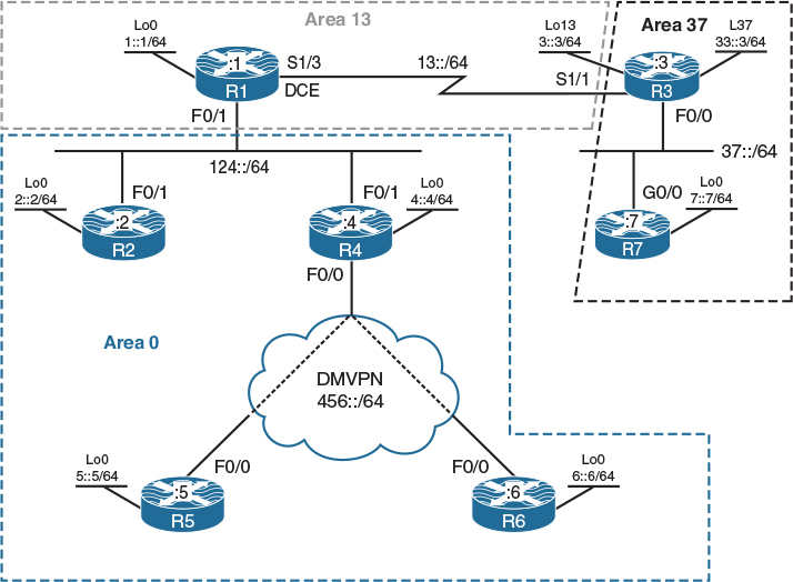
Figure 11-7 LSAs in OSPFv3
Figure 11-7 illustrates the topology that will be used in the following lab.
Task 1
Configure OSPF Area 0 on the F0/1 and loopback0 interfaces of R1, R2, and R4:
! On R1, R2, and R4:
Rx(config)# ipv6 unicast-routing
Rx(config)# interface loopback 0
Rx(config-if)# ipv6 ospf 1 area 0
Rx(config-if)# ipv6 ospf network point-to-point
Rx(config)# interface FastEthernet 0/1
Rx(config-if)# ipv6 ospf 1 area 0
! On R1:
R1(config)# ipv6 router ospf 1
R1(config-rtr)# router-id 0.0.0.1
R1# clear ipv6 ospf process
Reset ALL OSPF processes? [no]: Y
! On R2:
R2(config)# ipv6 router ospf 1
R2(config-rtr)# router-id 0.0.0.2
R2# clear ipv6 ospf process
Reset ALL OSPF processes? [no]: Y
! On R4:
R4(config)# ipv6 router ospf 1
R4(config-rtr)# router-id 0.0.0.4
R4# clear ipv6 ospf process
Reset ALL OSPF processes? [no]: Y
You should see the following console messages:
%OSPFv3-5-ADJCHG: Process 1, Nbr 0.0.0.1 on FastEthernet0/1 from LOADING to FULL,
Loading Done
%OSPFv3-5-ADJCHG: Process 1, Nbr 0.0.0.2 on FastEthernet0/1 from LOADING to FULL,
Loading Done
Let’s verify the configuration:
! On R1
R1# show ipv6 ospf neighbor
Neighbor ID Pri State Dead Time Interface ID Interface
0.0.0.2 1 FULL/DR 00:00:31 4 FastEthernet0/1
0.0.0.4 1 FULL/DROTHER 00:00:35 4 FastEthernet0/1
R1# show ipv6 route ospf
IPv6 Routing Table - default - 9 entries
Codes: C - Connected, L - Local, S - Static, U - Per-user Static route
B - BGP, HA - Home Agent, MR - Mobile Router, R - RIP
I1 - ISIS L1, I2 - ISIS L2, IA - ISIS interarea, IS - ISIS summary
D - EIGRP, EX - EIGRP external, NM - NEMO, ND - Neighbor Discovery
l - LISP
O - OSPF Intra, OI - OSPF Inter, OE1 - OSPF ext 1, OE2 - OSPF ext 2
ON1 - OSPF NSSA ext 1, ON2 - OSPF NSSA ext 2
O 2::/64 [110/2]
via FE80::2, FastEthernet0/1
O 4::/64 [110/2]
via FE80::4, FastEthernet0/1
Now let’s see which LSAs are propagated in this area so far:
R1# show ipv6 ospf database
OSPFv3 Router with ID (0.0.0.1) (Process ID 1)
Router Link States (Area 0)
ADV Router Age Seq# Fragment ID Link count Bits
0.0.0.1 511 0x80000002 0 1 None
0.0.0.2 512 0x80000002 0 1 None
0.0.0.4 368 0x80000001 0 1 None
Net Link States (Area 0)
ADV Router Age Seq# Link ID Rtr count
0.0.0.2 328 0x80000004 4 3
Link (Type-8) Link States (Area 0)
ADV Router Age Seq# Link ID Interface
0.0.0.1 716 0x80000001 22 Lo0
0.0.0.1 511 0x80000001 4 Fa0/1
0.0.0.2 561 0x80000001 4 Fa0/1
0.0.0.4 368 0x80000001 4 Fa0/1
Intra Area Prefix Link States (Area 0)
ADV Router Age Seq# Link ID Ref-lstype Ref-LSID
0.0.0.1 506 0x80000004 0 0x2001 0
0.0.0.2 512 0x80000003 0 0x2001 0
0.0.0.2 512 0x80000001 4096 0x2002 4
0.0.0.4 368 0x80000001 0 0x2001 0
You can see that four different types of LSAs are propagated: Router LSA, Network LSA, Link (Type-8) LSA, and Intra-Area Prefix (Type-9) LSA. Let’s examine each LSA type, starting with Router LSA.
Based on the preceding output, you can see that there are three Router LSAs, one per router:
R1# show ipv6 ospf database router adv-router 0.0.0.1
OSPFv3 Router with ID (0.0.0.1) (Process ID 1)
Router Link States (Area 0)
LS age: 827
Options: (V6-Bit, E-Bit, R-bit, DC-Bit)
LS Type: Router Links
Link State ID: 0
Advertising Router: 0.0.0.1
LS Seq Number: 80000002
Checksum: 0xCB27
Length: 40
Number of Links: 1
Link connected to: a Transit Network
Link Metric: 1
Local Interface ID: 4
Neighbor (DR) Interface ID: 4
Neighbor (DR) Router ID: 0.0.0.2
Router LSAs (Type-1) describe the link states and the cost of the local router’s links to the neighboring network objects (routers, multi-access networks, stub networks, or virtual links) within the same area. Just like in the previous OSPF version, Router LSAs are flooded within an area only. This LSA type also describes the router’s role, indicating whether the router is an ABR or ASBR, and if it’s one end of a given virtual link. As opposed to OSPFv2, however, Router LSAs in OSPFv3 only describe the topology relations but carry no addressing information. The question is, why?
The major drawback of OSPFv2, as opposed to Intermediate System to Intermediate System (IS-IS), was its inability to distinguish between a topology change and an addressing change. The addressing information in OSPFv2’s Router and Network LSA was so closely intertwined with the topological information that a change to an interface addressing was indistinguishable from a topology change where one interface or an entire router went away and a new one was brought up. These two categories of events require different handling, however: If a topology changes, OSPF must run the SPF algorithm to compute a new shortest path tree. On the other hand, if addressing changes, there is no need to run SPF and compute a new shortest path tree because that tree already exists and has not changed—just the addressing information present in the tree needs to be updated. OSPF could save a lot of work if it were able to tell a change to the topology from a change to the addressing.
This is where OSPFv3 is arguably an improvement. Router and Network LSAs no longer carry addressing information and instead are used exclusively to describe the topology. All addressing information from these LSA types has been moved out to the Intra-Area Prefix LSA (Type-9 LSA). Thanks to this, if only addressing changes, the affected router originates an updated Intra-Area Prefix LSA while keeping the existing Router and Network LSAs unchanged. As a result, other routers in the area won’t run SPF and instead will only update the addressing information already present in the shortest path tree, thus saving precious CPU cycles.
The output of the preceding show command reveals that Router LSAs do not carry the IPv6 addressing; instead, they only identify the following:
![]() Options field:
Options field:
![]() V6-Bit identifies that the router has the capability of forwarding transit IPv6 packets.
V6-Bit identifies that the router has the capability of forwarding transit IPv6 packets.
![]() E-Bit identifies the capability of the local router to accept external LSAs.
E-Bit identifies the capability of the local router to accept external LSAs.
![]() R-Bit indicates that the router can be used to route transit traffic.
R-Bit indicates that the router can be used to route transit traffic.
![]() DC-Bit identifies that the router is capable of running demand circuits.
DC-Bit identifies that the router is capable of running demand circuits.
![]() Advertising the router’s RID (in this case, 0.0.0.1).
Advertising the router’s RID (in this case, 0.0.0.1).
![]() The number of its own links this router advertises information about (in this case, just one).
The number of its own links this router advertises information about (in this case, just one).
![]() The individual interfaces of this router that connect to other network objects. In this case, this router’s interface connects to a transit network that is represented by its Designated Router (here, it is R2) and the corresponding Network LSA the Designated Router (DR) has originated.
The individual interfaces of this router that connect to other network objects. In this case, this router’s interface connects to a transit network that is represented by its Designated Router (here, it is R2) and the corresponding Network LSA the Designated Router (DR) has originated.
![]() The cost of the interface. In this case, the cost is 1 because the link operates at 100 Mbps.
The cost of the interface. In this case, the cost is 1 because the link operates at 100 Mbps.
![]() The interface IDs of this router and its neighbor connected by this link. In OSPFv3, interface IDs are used instead of IPv6 addresses to precisely indicate the interfaces that are connected together. Every interface on a router is assigned an interface ID, and the local router can learn about its neighbor’s interface ID from the received Hello packets.
The interface IDs of this router and its neighbor connected by this link. In OSPFv3, interface IDs are used instead of IPv6 addresses to precisely indicate the interfaces that are connected together. Every interface on a router is assigned an interface ID, and the local router can learn about its neighbor’s interface ID from the received Hello packets.
![]() The RID of the DR (in this case, 0.0.0.2). This means that R2 is the DR for this segment.
The RID of the DR (in this case, 0.0.0.2). This means that R2 is the DR for this segment.
Let’s examine LSA Type-2 or the Network LSAs. We will only see Network LSAs if there are multi-access segments in the topology with at least two routers. If we do not have multi-access segments (Broadcast or Non-Broadcast) in the topology, there will not be any Network LSAs. In the output of the show ipv6 ospf database command, we only saw a single Network LSA, and it was originated by R2 (0.0.0.2) because R2 is currently acting as the DR on the Ethernet network between R1, R2 and R4.
R1# show ipv6 ospf database network
OSPFv3 Router with ID (0.0.0.1) (Process ID 1)
Net Link States (Area 0)
LS age: 223
Options: (V6-Bit, E-Bit, R-bit, DC-Bit)
LS Type: Network Links
Link State ID: 4 (Interface ID of Designated Router)
Advertising Router: 0.0.0.2
LS Seq Number: 80000005
Checksum: 0x27CC
Length: 36
Attached Router: 0.0.0.2
Attached Router: 0.0.0.1
Attached Router: 0.0.0.4
Note Network LSAs no longer contain the address of the link. This information has also been moved out to Intra-Area Prefix LSAs. Network LSAs only state the RID of the routers that are attached to the multi-access segment. Remember, Router and Network LSAs in OSPFv3 no longer carry addressing information; they only describe how routers and networks are connected together.
Let’s now examine the Link LSAs or Type-8 LSAs. Keep in mind that these LSAs have only a link-wide flooding scope, meaning that a Link LSA advertised from an interface will be received and processed by the neighboring routers, but they will not flood it further. This can be slightly confusing because it causes different routers to have different link state database contents. Each router will only know its own Link LSAs and the Link LSAs originated by its neighbors for the common links. Nonetheless, this is expected behavior. When observing the following output, keep in mind that we are looking at the database of R1:
R1# show ipv6 ospf database
OSPFv3 Router with ID (0.0.0.1) (Process ID 1)
Router Link States (Area 0)
ADV Router Age Seq# Fragment ID Link count Bits
0.0.0.1 911 0x80000003 0 1 None
0.0.0.2 965 0x80000003 0 1 None
0.0.0.4 839 0x80000002 0 1 None
Net Link States (Area 0)
ADV Router Age Seq# Link ID Rtr count
0.0.0.2 720 0x80000005 4 3
Link (Type-8) Link States (Area 0)
ADV Router Age Seq# Link ID Interface
0.0.0.1 1157 0x80000002 22 Lo0
0.0.0.1 911 0x80000002 4 Fa0/1
0.0.0.2 965 0x80000002 4 Fa0/1
0.0.0.4 839 0x80000002 4 Fa0/1
Intra Area Prefix Link States (Area 0)
ADV Router Age Seq# Link ID Ref-lstype Ref-LSID
0.0.0.1 911 0x80000005 0 0x2001 0
0.0.0.2 965 0x80000004 0 0x2001 0
0.0.0.2 965 0x80000002 4096 0x2002 4
0.0.0.4 839 0x80000002 0 0x2001 0
There are four Link LSAs in R1’s link state database: two from 0.0.0.1, one from 0.0.0.2, and another one from 0.0.0.4. The reason R1 has originated two entries is because it is running OSPFv3 on two interfaces: loopback0 and F0/1. Other Link LSAs are received from the neighbors R2 and R4. Note that both R2 and R4 might have originated multiple Link LSAs, but each Link LSA is related only to a particular interface and is only sent out from that interface.
Let’s now check the link state database on R2:
! On R2:
R2# show ipv6 ospf database link
Link (Type-8) Link States (Area 0)
ADV Router Age Seq# Link ID Interface
0.0.0.2 1159 0x80000002 22 Lo0
0.0.0.1 1107 0x80000002 4 Fa0/1
0.0.0.2 1159 0x80000002 4 Fa0/1
0.0.0.4 1035 0x80000002 4 Fa0/1
(The output is modified to show the section for LSA Type-8s only)
! On R4:
R4# show ipv6 ospf database link
Link (Type-8) Link States (Area 0)
ADV Router Age Seq# Link ID Interface
0.0.0.4 1209 0x80000002 22 Lo0
0.0.0.1 1282 0x80000002 4 Fa0/1
0.0.0.2 1336 0x80000002 4 Fa0/1
0.0.0.4 1209 0x80000002 4 Fa0/1
(The output is modified to show the section for LSA Type-8s only)
Let’s examine these LSAs in detail. Link LSAs provide the link-local IPv6 address of the local router to all other routers attached to the link. Link LSAs also convey all IPv6 prefixes associated with the interface for which the Link LSA was originated.
! On R1:
R1# show ipv6 ospf database Link adv-router 0.0.0.1
OSPFv3 Router with ID (0.0.0.1) (Process ID 1)
Link (Type-8) Link States (Area 0)
LS age: 1637
Options: (V6-Bit, E-Bit, R-bit, DC-Bit)
LS Type: Link-LSA (Interface: Loopback0)
Link State ID: 22 (Interface ID)
Advertising Router: 0.0.0.1
LS Seq Number: 80000002
Checksum: 0xCEB7
Length: 56
Router Priority: 1
Link Local Address: FE80::213:7FFF:FE10:7590
Number of Prefixes: 1
Prefix Address: 1::
Prefix Length: 64, Options: None
LS age: 1390
Options: (V6-Bit, E-Bit, R-bit, DC-Bit)
LS Type: Link-LSA (Interface: FastEthernet0/1)
Link State ID: 4 (Interface ID)
Advertising Router: 0.0.0.1
LS Seq Number: 80000002
Checksum: 0x1904
Length: 56
Router Priority: 1
Link Local Address: FE80::1
Number of Prefixes: 1
Prefix Address: 124::
Prefix Length: 64, Options: None
You can see two Link LSAs—one per interface. You can also see the link local IPv6 address associated with each interface. Because the link-local IPv6 address of the Lo0 interface was not statically configured, a Modified EUI-64 format was used to generate one.
Let’s look at the last two lines of the preceding output. Currently, these lines say that F0/1 uses a prefix of 124:: with a length of /64. If we configure another IPv6 address on the F0/1 interface, we should see two prefixes.
! On R1:
R1(config)# interface FastEthernet 0/1
R1(config-if)# ipv6 address 111::111/64
R1# show ipv6 ospf database Link interface FastEthernet 0/1 adv-router 0.0.0.1
OSPFv3 Router with ID (0.0.0.1) (Process ID 1)
Link (Type-8) Link States (Area 0)
LS age: 17
Options: (V6-Bit, E-Bit, R-bit, DC-Bit)
LS Type: Link-LSA (Interface: FastEthernet0/1)
Link State ID: 4 (Interface ID)
Advertising Router: 0.0.0.1
LS Seq Number: 80000004
Checksum: 0x10AB
Length: 68
Router Priority: 1
Link Local Address: FE80::1
Number of Prefixes: 2
Prefix Address: 111::
Prefix Length: 64, Options: None
Prefix Address: 124::
Prefix Length: 64, Options: None
Now, there are two prefixes advertised for the interface, confirming the assumption. Let’s remove the added prefix:
R1(config)# interface FastEthernet 0/1
R1(config-if)# no ipv6 address 111::111/64
The last LSA type is the Intra-Area Prefix LSA, or Type-9 LSA (Type-9 LSA will be used here for brevity). Let’s examine this LSA:
R1# show ipv6 ospf database prefix adv-router 0.0.0.1
OSPFv3 Router with ID (0.0.0.1) (Process ID 1)
Intra Area Prefix Link States (Area 0)
Routing Bit Set on this LSA
LS age: 221
LS Type: Intra-Area-Prefix-LSA
Link State ID: 0
Advertising Router: 0.0.0.1
LS Seq Number: 80000006
Checksum: 0x6B7
Length: 44
Referenced LSA Type: 2001
Referenced Link State ID: 0
Referenced Advertising Router: 0.0.0.1
Number of Prefixes: 1
Prefix Address: 1::
Prefix Length: 64, Options: None, Metric: 1
The output of the preceding show command reveals the intra-area prefixes carried by Type-9 LSAs. Every router advertises its directly connected networks in Type-9 LSAs, which are then flooded across the area. In fact, a single router can originate multiple Type-9 LSAs—recall that OSPFv2 used to advertise directly connected networks in Router LSAs (stub networks) and in Network LSAs (transit networks). OSPFv3 moved this addressing information out from Router and Network LSAs into Intra-Area Prefix LSAs (Type-9 LSAs), but the information in these Type-9 LSAs refers back to either Router or Network LSAs where the information was previously stored. Therefore, a router will originate one Type-9 LSA for all stub networks that were formerly present in its Router LSA, plus one Type-9 LSA for each transit network where the router is a DR and has originated a corresponding Network LSA. The specific LSA (Router or Network) a Type-9 LSA refers back to is identified by the entries “Referenced LSA Type” (Router or Network LSA), “Referenced Link State ID” (0 for Router LSA, Interface ID for Network LSA), or “Referenced Advertising Router.”
Task 2
Configure OSPF Area 13 on the S1/3 interface of R1 and the S1/1 and loopback13 interfaces of R3:
! On R1:
R1(config)# interface Serial 1/3
R1(config-if)# ipv6 ospf 1 area 13
! On R3:
R3(config)# ipv6 unicast-routing
R3(config)# int loopback 13
R3(config-if)# ipv6 ospf 1 area 13
R3(config-if)# ipv6 ospf network point-to-point
R3(config)# interface Serial 1/1
R3(config-if)# ipv6 ospf 1 area 13
You should see the following console messages:
%OSPFv3-5-ADJCHG: Process 1, Nbr 0.0.0.1 on Serial1/1 from LOADING to FULL,
Loading Done
Let’s verify the configuration:
! On R3:
R3# show ipv6 route ospf
IPv6 Routing Table - default - 11 entries
Codes: C - Connected, L - Local, S - Static, U - Per-user Static route
B - BGP, HA - Home Agent, MR - Mobile Router, R - RIP
I1 - ISIS L1, I2 - ISIS L2, IA - ISIS interarea, IS - ISIS summary
D - EIGRP, EX - EIGRP external, NM - NEMO, ND - Neighbor Discovery
l - LISP
O - OSPF Intra, OI - OSPF Inter, OE1 - OSPF ext 1, OE2 - OSPF ext 2
ON1 - OSPF NSSA ext 1, ON2 - OSPF NSSA ext 2
OI 1::/64 [110/65]
via FE80::1, Serial1/1
OI 2::/64 [110/66]
via FE80::1, Serial1/1
OI 4::/64 [110/66]
via FE80::1, Serial1/1
OI 124::/64 [110/65]
via FE80::1, Serial1/1
! On R1:
R1# show ipv6 route ospf
IPv6 Routing Table - default - 10 entries
Codes: C - Connected, L - Local, S - Static, U - Per-user Static route
B - BGP, HA - Home Agent, MR - Mobile Router, R - RIP
I1 - ISIS L1, I2 - ISIS L2, IA - ISIS interarea, IS - ISIS summary
D - EIGRP, EX - EIGRP external, NM - NEMO, ND - Neighbor Discovery
l - LISP
O - OSPF Intra, OI - OSPF Inter, OE1 - OSPF ext 1, OE2 - OSPF ext 2
ON1 - OSPF NSSA ext 1, ON2 - OSPF NSSA ext 2
O 2::/64 [110/2]
via FE80::2, FastEthernet0/1
O 3::/64 [110/65]
via FE80::3, Serial1/3
O 4::/64 [110/2]
via FE80::4, FastEthernet0/1
Let’s see the OSPFv3 database on R3:
! On R3:
R3# show ipv6 ospf database
OSPFv3 Router with ID (0.0.0.3) (Process ID 1)
Router Link States (Area 13)
ADV Router Age Seq# Fragment ID Link count Bits
0.0.0.1 156 0x80000002 0 1 B
0.0.0.3 156 0x80000002 0 1 None
Inter Area Prefix Link States (Area 13)
ADV Router Age Seq# Prefix
0.0.0.1 433 0x80000001 1::/64
0.0.0.1 433 0x80000001 2::/64
0.0.0.1 433 0x80000001 4::/64
0.0.0.1 433 0x80000001 124::/64
Link (Type-8) Link States (Area 13)
ADV Router Age Seq# Link ID Interface
0.0.0.3 311 0x80000001 23 Lo13
0.0.0.1 433 0x80000001 8 Se1/1
0.0.0.3 156 0x80000001 6 Se1/1
Intra Area Prefix Link States (Area 13)
ADV Router Age Seq# Link ID Ref-lstype Ref-LSID
0.0.0.1 433 0x80000001 0 0x2001 0
0.0.0.3 156 0x80000003 0 0x2001 0
Here, you can see LSA Types 1 (Router), 3 (Inter-Area Prefix), 8 (Link), and 9 (Intra-Area Prefix).
Note Because there is no multi-access network with at least two OSPF routers in Area 13, there is no DR/BDR election, and consequently no Network LSA is originated.
Let’s examine these LSAs starting with the Router LSA:
R3# show ipv6 ospf database router adv-router 0.0.0.3
OSPFv3 Router with ID (0.0.0.3) (Process ID 1)
Router Link States (Area 13)
LS age: 1040
Options: (V6-Bit, E-Bit, R-bit, DC-Bit)
LS Type: Router Links
Link State ID: 0
Advertising Router: 0.0.0.3
LS Seq Number: 80000029
Checksum: 0x3155
Length: 40
Number of Links: 1
Link connected to: another Router (point-to-point)
Link Metric: 64
Local Interface ID: 6
Neighbor Interface ID: 8
Neighbor Router ID: 0.0.0.1
You can see that the link is a point-to-point interface for which there is no requirement for DR/BDR. Router LSAs describe routers present in the topology and their interfaces to directly attached network objects. In this case, you can see that the local router is connected to R1 (0.0.0.1) and the cost of the local router’s interface toward R1 is 64. Again, addressing information is no longer present.
Router LSAs also describe the role of the router, whether the router is an ABR or ASBR, and whether it is a virtual-link endpoint. Because R1 is an ABR, you should see this role identified in its Router LSAs. Let’s verify:
! On R1:
R1# show ipv6 ospf database router adv-router 0.0.0.1 | begin Area 13
Router Link States (Area 13)
LS age: 1605
Options: (V6-Bit, E-Bit, R-bit, DC-Bit)
LS Type: Router Links
Link State ID: 0
Advertising Router: 0.0.0.1
LS Seq Number: 80000029
Checksum: 0x6421
Length: 40
Area Border Router
Number of Links: 1
Link connected to: another Router (point-to-point)
Link Metric: 64
Local Interface ID: 8
Neighbor Interface ID: 6
Neighbor Router ID: 0.0.0.3
Let’s now examine the Inter-Area Prefix LSAs on R3:
! On R3:
R3# show ipv6 ospf database inter-area prefix
OSPFv3 Router with ID (0.0.0.3) (Process ID 1)
Inter Area Prefix Link States (Area 13)
Routing Bit Set on this LSA
LS age: 698
LS Type: Inter Area Prefix Links
Link State ID: 0
Advertising Router: 0.0.0.1
LS Seq Number: 80000029
Checksum: 0x3596
Length: 36
Metric: 1
Prefix Address: 1::
Prefix Length: 64, Options: None
Routing Bit Set on this LSA
LS age: 698
LS Type: Inter Area Prefix Links
Link State ID: 1
Advertising Router: 0.0.0.1
LS Seq Number: 80000029
Checksum: 0x3D8B
Length: 36
Metric: 2
Prefix Address: 2::
Prefix Length: 64, Options: None
Routing Bit Set on this LSA
LS age: 698
LS Type: Inter Area Prefix Links
Link State ID: 2
Advertising Router: 0.0.0.1
LS Seq Number: 80000029
Checksum: 0x4B7A
Length: 36
Metric: 2
Prefix Address: 4::
Prefix Length: 64, Options: None
Routing Bit Set on this LSA
LS age: 698
LS Type: Inter Area Prefix Links
Link State ID: 3
Advertising Router: 0.0.0.1
LS Seq Number: 80000029
Checksum: 0xC7DC
Length: 36
Metric: 1
Prefix Address: 124::
Prefix Length: 64, Options: None
Let’s verify these prefixes on R1. Remember that from R1’s perspective, these routes are intra-area prefixes. Let’s verify the cost from R1’s perspective:
! On R1:
R1# show ipv6 ospf inter FastEthernet 0/1 | include Cost
Network Type BROADCAST, Cost: 1
R1# show ipv6 route 4::/64 | include metric
Known via "ospf 1", distance 110, metric 2, type intra area
R1# show ipv6 route 2::/64 | include metric
Known via "ospf 1", distance 110, metric 2, type intra area
R1# show ipv6 ospf inter lo0 | include Cost
Network Type POINT_TO_POINT, Cost: 1
Now, these routes are inter-area routes from R3’s perspective, and because the cost in OSPF is cumulative, it will be the sum of what R1 advertised plus the cost of the link to R1. Let’s verify this information:
! On R3:
R3# show ipv6 route ospf
IPv6 Routing Table - default - 11 entries
Codes: C - Connected, L - Local, S - Static, U - Per-user Static route
B - BGP, HA - Home Agent, MR - Mobile Router, R - RIP
I1 - ISIS L1, I2 - ISIS L2, IA - ISIS interarea, IS - ISIS summary
D - EIGRP, EX - EIGRP external, NM - NEMO, ND - Neighbor Discovery
l – LISP
O - OSPF Intra, OI - OSPF Inter, OE1 - OSPF ext 1, OE2 - OSPF ext 2
ON1 - OSPF NSSA ext 1, ON2 - OSPF NSSA ext 2
OI 1::/64 [110/65]
via FE80::1, Serial1/1
OI 2::/64 [110/66]
via FE80::1, Serial1/1
OI 4::/64 [110/66]
via FE80::1, Serial1/1
OI 124::/64 [110/65]
via FE80::1, Serial1/1
You can see that the prefixes are inter-area, so let’s examine the database of R3 for one of these prefixes:
R3# show ipv6 ospf database inter-area prefix 1::/64
OSPFv3 Router with ID (0.0.0.3) (Process ID 1)
Inter Area Prefix Link States (Area 13)
Routing Bit Set on this LSA
LS age: 1508
LS Type: Inter Area Prefix Links
Link State ID: 0
Advertising Router: 0.0.0.1
LS Seq Number: 80000029
Checksum: 0x3596
Length: 36
Metric: 1
Prefix Address: 1::
Prefix Length: 64, Options: None
You can see that the advertising router is R1 (0.0.0.1). Let’s see what R3’s cost is to reach R1 by looking at the cost of the interface between R3 and R1:
R3# show ipv6 ospf interface Serial 1/1 | include Cost
Network Type POINT_TO_POINT, Cost: 64
So R3’s cost to R1 is 64, and R1’s cost to the 1::/64 prefix is 1; therefore, R3’s overall cost to network 1::/64 is 65.
Let’s examine Link LSAs:
R3# show ipv6 ospf database
OSPFv3 Router with ID (0.0.0.3) (Process ID 1)
Link (Type-8) Link States (Area 13)
ADV Router Age Seq# Link ID Interface
0.0.0.3 1569 0x80000029 23 Lo13
0.0.0.1 1992 0x80000029 8 Se1/1
0.0.0.3 1569 0x80000029 6 Se1/1
You can see that R3 (0.0.0.3) has two entries: one for its Lo0 interface and one for its S1/1 interface. Let’s examine these closer:
R3# show ipv6 ospf database link adv-router 0.0.0.3
OSPFv3 Router with ID (0.0.0.3) (Process ID 1)
Link (Type-8) Link States (Area 13)
LS age: 1491
Options: (V6-Bit, E-Bit, R-bit, DC-Bit)
LS Type: Link-LSA (Interface: Loopback13)
Link State ID: 23 (Interface ID)
Advertising Router: 0.0.0.3
LS Seq Number: 80000029
Checksum: 0xCD26
Length: 56
Router Priority: 1
Link Local Address: FE80::21B:54FF:FEB7:7770
Number of Prefixes: 1
Prefix Address: 3::
Prefix Length: 64, Options: None
LS age: 1491
Options: (V6-Bit, E-Bit, R-bit, DC-Bit)
LS Type: Link-LSA (Interface: Serial1/1)
Link State ID: 6 (Interface ID)
Advertising Router: 0.0.0.3
LS Seq Number: 80000029
Checksum: 0x956C
Length: 56
Router Priority: 1
Link Local Address: FE80::3
Number of Prefixes: 1
Prefix Address: 13::
Prefix Length: 64, Options: None
These were explained in the previous task, so let’s move on to intra-area prefixes:
R3# show ipv6 ospf database prefix adv-router 0.0.0.3
OSPFv3 Router with ID (0.0.0.3) (Process ID 1)
Intra Area Prefix Link States (Area 13)
Routing Bit Set on this LSA
LS age: 1844
LS Type: Intra-Area-Prefix-LSA
Link State ID: 0
Advertising Router: 0.0.0.3
LS Seq Number: 8000002B
Checksum: 0xC031
Length: 56
Referenced LSA Type: 2001
Referenced Link State ID: 0
Referenced Advertising Router: 0.0.0.3
Number of Prefixes: 2
Prefix Address: 3::
Prefix Length: 64, Options: None, Metric: 1
Prefix Address: 13::
Prefix Length: 64, Options: None, Metric: 64
Task 3
Configure OSPF Area 37 on the F0/0 and Lo37 interfaces of R3 and the G0/0 and Lo0 interfaces of R7. These routers should see all the routes from the other areas in this routing domain.
Once the routers in Area 37 are configured, a virtual link must be configured to extend Area 0 to the routers in Area 37:
! On R3:
R3(config)# interface FastEthernet 0/0
R3(config-if)# ipv6 ospf 1 area 37
R3(config)# interface loopback 37
R3(config-if)# ipv6 ospf 1 area 37
R3(config-if)# ipv6 ospf network point-to-point
! On R7:
R7(config)# ipv6 unicast-routing
R7(config)# router ospfv3 1
R7(config-router)# address-family ipv6 unicast
R7(config-router-af)# router-id 0.0.0.7
R7(config)# interface GigabitEthernet 0/0
R7(config-if)# ospfv3 1 ipv6 area 37
You should see the following console message:
%OSPFv3-5-ADJCHG: Process 1, IPv6, Nbr 0.0.0.3 on GigabitEthernet0/0 from LOADING
to FULL, Loading Done
R7(config)# interface loopback 0
R7(config-if)# ospfv3 1 ipv6 area 37
R7(config-if)# ospfv3 network point-to-point
Let’s verify the configuration:
! On R7:
R7# show ipv6 route ospf
IPv6 Routing Table - default - 6 entries
Codes: C - Connected, L - Local, S - Static, U - Per-user Static route
B - BGP, HA - Home Agent, MR - Mobile Router, R - RIP
H - NHRP, I1 - ISIS L1, I2 - ISIS L2, IA - ISIS interarea
IS - ISIS summary, D - EIGRP, EX - EIGRP external, NM - NEMO
ND - ND Default, NDp - ND Prefix, DCE - Destination, NDr - Redirect
O - OSPF Intra, OI - OSPF Inter, OE1 - OSPF ext 1, OE2 - OSPF ext 2
ON1 - OSPF NSSA ext 1, ON2 - OSPF NSSA ext 2, ls - LISP site
ld - LISP dyn-EID, a - Application
O 33::/64 [110/2]
via FE80::3, GigabitEthernet0/0
You can only see the prefix that is advertised by R3. The reason is that Area 37 is not touching Area 0. Let’s configure the virtual link on R3 and R1. Because a virtual link uses Router IDs to identify its endpoints, let’s find out the RID of R1 and R3:
! On R1:
R1# show ipv6 ospf | inc ID
Routing Process "ospfv3 1" with ID 0.0.0.1
! On R3:
R3# show ipv6 ospf | inc ID
Routing Process "ospfv3 1" with ID 0.0.0.3
Next, you should check and see if filtering was configured in the transit area, or if the transit area is a stub of any kind. Because you have configured these routers and know that you have not filtered any prefixes or configured any of the areas as stubs, you can bypass this verification.
Next to be verified is the cumulative cost between the virtual-link endpoints R1 and R3. The reason is that the cost of a virtual link is inherited from the cost of the shortest path between the virtual-link endpoints and cannot be configured manually. Because a virtual link is treated as a point-to-point unnumbered interface, its cost must be less than 65535, which is the maximum OSPF metric for an interface and is used to indicate a nontransit link. Therefore, it is advisable that you verify whether the path between R1 and R3 reaches or even exceeds this metric; in such case, the virtual link would not come up.
The last step is to configure the virtual link:
! On R1:
R1(config)# ipv6 router ospf 1
R1(config-rtr)# area 13 virtual-link 0.0.0.3
! On R3:
R3(config)# ipv6 router ospf 1
R3(config-rtr)# area 13 virtual-link 0.0.0.1
You should see the following console message:
%OSPFv3-5-ADJCHG: Process 1, Nbr 0.0.0.1 on OSPFv3_VL0 from LOADING to FULL,
Loading Done
Let’s verify the configuration:
! On R3:
R3# show ipv6 ospf neighbor
Neighbor ID Pri State Dead Time Interface ID Interface
0.0.0.1 0 FULL/ - 00:00:03 23 OSPFv3_VL0
0.0.0.1 0 FULL/ - 00:00:36 8 Serial1/1
0.0.0.7 1 FULL/BDR 00:00:32 3 FastEthernet0/0
R3# show ipv6 ospf virtual-links
Virtual Link OSPFv3_VL0 to router 0.0.0.1 is up
Interface ID 25, IPv6 address 13::1
Run as demand circuit
DoNotAge LSA allowed.
Transit area 13, via interface Serial1/1, Cost of using 64
Transmit Delay is 1 sec, State POINT_TO_POINT,
Timer intervals configured, Hello 10, Dead 40, Wait 40, Retransmit 5
Adjacency State FULL (Hello suppressed)
(The rest of the output is omitted for brevity)
Let’s verify the database of R3:
! On R3:
R3# show ipv6 ospf database router adv-router 0.0.0.1
OSPFv3 Router with ID (0.0.0.3) (Process ID 1)
Router Link States (Area 0)
Routing Bit Set on this LSA
LS age: 1 (DoNotAge)
Options: (V6-Bit, E-Bit, R-bit, DC-Bit)
LS Type: Router Links
Link State ID: 0
Advertising Router: 0.0.0.1
LS Seq Number: 8000002F
Checksum: 0x4DEF
Length: 56
Area Border Router
Number of Links: 2
Link connected to: a Virtual Link
Link Metric: 64
Local Interface ID: 23
Neighbor Interface ID: 25
Neighbor Router ID: 0.0.0.3
(The rest of the output is omitted for brevity)
! On R7:
R7# show ipv6 route ospf
IPv6 Routing Table - default - 14 entries
Codes: C - Connected, L - Local, S - Static, U - Per-user Static route
B - BGP, HA - Home Agent, MR - Mobile Router, R - RIP
H - NHRP, I1 - ISIS L1, I2 - ISIS L2, IA - ISIS interarea
IS - ISIS summary, D - EIGRP, EX - EIGRP external, NM - NEMO
ND - ND Default, NDp - ND Prefix, DCE - Destination, NDr - Redirect
O - OSPF Intra, OI - OSPF Inter, OE1 - OSPF ext 1, OE2 - OSPF ext 2
ON1 - OSPF NSSA ext 1, ON2 - OSPF NSSA ext 2, ls - LISP site
ld - LISP dyn-EID, a - Application
OI 1::/64 [110/66]
via FE80::3, GigabitEthernet0/0
OI 2::/64 [110/67]
via FE80::3, GigabitEthernet0/0
OI 3::/64 [110/2]
via FE80::3, GigabitEthernet0/0
OI 3::3/128 [110/1]
via FE80::3, GigabitEthernet0/0
OI 4::/64 [110/67]
via FE80::3, GigabitEthernet0/0
OI 13::/64 [110/65]
via FE80::3, GigabitEthernet0/0
OI 13::1/128 [110/65]
via FE80::3, GigabitEthernet0/0
O 33::/64 [110/2]
via FE80::3, GigabitEthernet0/0
OI 124::/64 [110/66]
via FE80::3, GigabitEthernet0/0
Task 4
Configure OSPF Area 0 on the DMVPN network. The OSPFv3 network type for the DMVPN network should be configured as broadcast, like so:
! On R4:
R4(config)# interface tunnel 1
R4(config-if)# ipv6 ospf network broadcast
R4(config-if)# ipv6 ospf 1 area 0
! On R5:
R5(config)# ipv6 unicast-routing
R5(config)# ipv6 router ospf 1
R5(config-rtr)# router-id 0.0.0.5
R5(config)# interface tunnel 1
R5(config-if)# ipv6 ospf priority 0
R5(config-if)# ipv6 ospf network broadcast
R5(config-if)# ipv6 ospf 1 area 0
You should see the following console message:
%OSPFv3-5-ADJCHG: Process 1, Nbr 0.0.0.4 on Tunnel1 from LOADING to FULL, Loading Done
! On R6:
R6(config)# ipv6 unicast-routing
R6(config)# ipv6 router ospf 1
R6(config-rtr)# router-id 0.0.0.6
R6(config)# interface tunnel 1
R6(config-if)# ipv6 ospf priority 0
R6(config-if)# ipv6 ospf network broadcast
R6(config-if)# ipv6 ospf 1 area 0
You should also see this console message:
%OSPFv3-5-ADJCHG: Process 1, Nbr 0.0.0.4 on Tunnel1 from LOADING to FULL, Loading Done
Let’s verify the configuration:
! On R6:
R6# show ipv6 route ospf
IPv6 Routing Table - default - 16 entries
Codes: C - Connected, L - Local, S - Static, U - Per-user Static route
B - BGP, HA - Home Agent, MR - Mobile Router, R - RIP
I1 - ISIS L1, I2 - ISIS L2, IA - ISIS interarea, IS - ISIS summary
D - EIGRP, EX - EIGRP external, NM - NEMO, ND - Neighbor Discovery
l - LISP
O - OSPF Intra, OI - OSPF Inter, OE1 - OSPF ext 1, OE2 - OSPF ext 2
ON1 - OSPF NSSA ext 1, ON2 - OSPF NSSA ext 2
O 1::/64 [110/1002]
via FE80::4, Tunnel1
O 2::/64 [110/1002]
via FE80::4, Tunnel1
OI 3::/64 [110/1066]
via FE80::4, Tunnel1
OI 3::3/128 [110/1065]
via FE80::4, Tunnel1
O 4::/64 [110/1001]
via FE80::4, Tunnel1
OI 7::/64 [110/1067]
via FE80::4, Tunnel1
OI 13::/64 [110/1065]
via FE80::4, Tunnel1
OI 13::1/128 [110/1001]
via FE80::4, Tunnel1
OI 33::/64 [110/1066]
via FE80::4, Tunnel1
OI 37::/64 [110/1066]
via FE80::4, Tunnel1
O 124::/64 [110/1001]
via FE80::4, Tunnel1
R6# show ipv6 ospf database
OSPFv3 Router with ID (0.0.0.6) (Process ID 1)
Router Link States (Area 0)
ADV Router Age Seq# Fragment ID Link count Bits
0.0.0.1 1172 0x80000030 0 2 B
0.0.0.2 2048 0x8000002E 0 1 None
0.0.0.3 3 (DNA) 0x80000002 0 1 B
0.0.0.4 253 0x8000002E 0 2 None
0.0.0.5 164 0x80000001 0 1 None
0.0.0.6 83 0x80000001 0 1 None
Net Link States (Area 0)
ADV Router Age Seq# Link ID Rtr count
0.0.0.2 1785 0x80000030 4 3
0.0.0.4 84 0x80000004 23 3
Inter Area Prefix Link States (Area 0)
ADV Router Age Seq# Prefix
0.0.0.1 1172 0x8000002B 13::/64
0.0.0.1 669 0x8000002B 3::/64
0.0.0.1 1437 0x80000001 13::1/128
0.0.0.1 1401 0x80000001 3::3/128
0.0.0.3 8 (DNA) 0x80000001 13::/64
0.0.0.3 8 (DNA) 0x80000001 13::1/128
0.0.0.3 8 (DNA) 0x80000001 3::/64
0.0.0.3 8 (DNA) 0x80000001 33::/64
0.0.0.3 8 (DNA) 0x80000001 7::/64
0.0.0.3 8 (DNA) 0x80000001 37::/64
0.0.0.3 3 (DNA) 0x80000001 3::3/128
Link (Type-8) Link States (Area 0)
ADV Router Age Seq# Link ID Interface
0.0.0.4 305 0x80000001 23 Tu1
0.0.0.5 164 0x80000001 23 Tu1
0.0.0.6 84 0x80000001 23 Tu1
Intra Area Prefix Link States (Area 0)
ADV Router Age Seq# Link ID Ref-lstype Ref-LSID
0.0.0.1 180 0x80000031 0 0x2001 0
0.0.0.2 2048 0x8000002F 0 0x2001 0
0.0.0.2 2048 0x8000002F 4096 0x2002 4
0.0.0.4 253 0x8000002F 0 0x2001 0
0.0.0.4 253 0x80000001 23552 0x2002 23
In the output of the preceding command, the entries with (DNA) are the prefixes learned over the virtual link. Remember that a virtual link runs as a demand circuit, which is similar to running the ip ospf demand-circuit command on a dial-up link such as ISDN. Let’s verify:
! On R3:
R3# show ipv6 ospf virtual-links | include demand
Run as demand circuit
Erase the startup configuration and reload the routers before proceeding to the next lab.
Lab 11-5: EIGRPv6
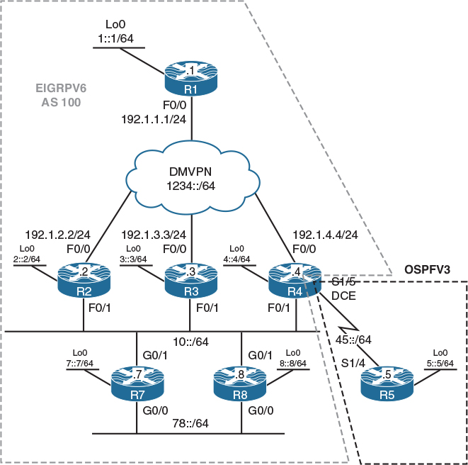
Figure 11-8 EIGRPv6
Figure 11-8 illustrates the topology that will be used in the following lab.
EIGRPv6—which is only a fancy name for IPv6-enabled EIGRP and does not really refer to a specific EIGRP version—operates in a very similar manner to its predecessor, EIGRP for IPv4. Both versions of EIGRP perform the following tasks:
![]() EIGRP routers build a topology table using each of their neighbors’ advertisements, and then only the best routes from the topology table are placed into the routers’ routing tables. For each route, the next hop that provides the shortest loop-free path is called a successor, while a next hop that provides a higher-cost loop-free path is called a feasible successor.
EIGRP routers build a topology table using each of their neighbors’ advertisements, and then only the best routes from the topology table are placed into the routers’ routing tables. For each route, the next hop that provides the shortest loop-free path is called a successor, while a next hop that provides a higher-cost loop-free path is called a feasible successor.
![]() Both versions of EIGRP use the same Diffusing Update Algorithm (DUAL) for fast convergence and to guarantee loop-free operation.
Both versions of EIGRP use the same Diffusing Update Algorithm (DUAL) for fast convergence and to guarantee loop-free operation.
![]() Both versions of EIGRP only send routing updates about paths that have changed once an EIGRP network has converged.
Both versions of EIGRP only send routing updates about paths that have changed once an EIGRP network has converged.
![]() Both versions of EIGRP send out Hello packets every 5 seconds on high-bandwidth links and every 60 seconds on low-bandwidth multipoint links to verify neighboring router connectivity.
Both versions of EIGRP send out Hello packets every 5 seconds on high-bandwidth links and every 60 seconds on low-bandwidth multipoint links to verify neighboring router connectivity.
![]() Both versions of EIGRP rely on the metrics of Bandwidth, Delay, Reliability, and Load to compute the composite metric of individual routes. By default, only Bandwidth and Delay are taken into account.
Both versions of EIGRP rely on the metrics of Bandwidth, Delay, Reliability, and Load to compute the composite metric of individual routes. By default, only Bandwidth and Delay are taken into account.
![]() Both versions of EIGRP use the Reliable Transport Protocol (RTP) to guarantee the delivery of EIGRP packets.
Both versions of EIGRP use the Reliable Transport Protocol (RTP) to guarantee the delivery of EIGRP packets.
Task 1
Configure OSPFv3 Area 0 on the loopback0 and s1/4 interfaces of R5 and the s1/5 interface of R4. The loopback0 interface of R5 should be advertised with its correct mask. R4 and R5’s RIDs should be configured to be 0.0.0.4 and 0.0.0.5, respectively.
! On R5:
R5(config)# ipv6 unicast-routing
R5(config)# ipv6 router ospf 1
R5(config-rtr)# router-id 0.0.0.5
R5(config)# interface loopback 0
R5(config-if)# ipv6 ospf network point-to-point
R5(config-if)# ipv6 ospf 1 area 0
R5(config)# interface Serial 1/4
R5(config-if)# ipv6 ospf 1 area 0
! On R4:
R4(config)# ipv6 unicast-routing
R4(config)# ipv6 router ospf 1
R4(config-rtr)# router-id 0.0.0.4
R4(config)# interface Serial 1/5
R4(config-if)# ipv6 ospf 1 area 0
You should see the following console message:
%OSPFv3-5-ADJCHG: Process 1, Nbr 0.0.0.5 on Serial1/5 from LOADING to FULL, Loading Done
R4# show ipv6 route ospf
IPv6 Routing Table - default - 10 entries
Codes: C - Connected, L - Local, S - Static, U - Per-user Static route
B - BGP, HA - Home Agent, MR - Mobile Router, R - RIP
I1 - ISIS L1, I2 - ISIS L2, IA - ISIS interarea, IS - ISIS summary
D - EIGRP, EX - EIGRP external, NM - NEMO, ND - Neighbor Discovery
l - LISP
O - OSPF Intra, OI - OSPF Inter, OE1 - OSPF ext 1, OE2 - OSPF ext 2
ON1 - OSPF NSSA ext 1, ON2 - OSPF NSSA ext 2
O 5::/64 [110/782]
via FE80::5, Serial1/5
R4# ping 5::5
Type escape sequence to abort.
Sending 5, 100-byte ICMP Echos to 5::5, timeout is 2 seconds:
!!!!!
Success rate is 100 percent (5/5), round-trip min/avg/max = 28/29/32 ms
Task 2
Configure EIGRPv6 AS 100 on the loopback0, G0/1, and G0/0 interfaces of R7 and R8. These routers should be configured with EIGRPv6 named mode. The RIDs of the R7 and R8 routers should be configured as 0.0.0.7 and 0.0.0.8, respectively.
When configuring EIGRPv6, you must configure the EIGRP RID; otherwise, the EIGRP process will not start.
! On R7:
R7(config)# ipv6 unicast-routing
R7(config)# router eigrp A
R7(config-router)# address-family ipv6 unicast as 100
R7(config-router-af)# eigrp router-id 0.0.0.7
! On R8:
R8(config)# ipv6 unicast-routing
R8(config)# router eigrp B
R8(config-router)# address-family ipv6 unicast as 100
R8(config-router-af)# eigrp router-id 0.0.0.8
You should see the following console message:
%DUAL-5-NBRCHANGE: EIGRP-IPv6 100: Neighbor FE80::7 (GigabitEthernet0/0) is up:
new adjacency
%DUAL-5-NBRCHANGE: EIGRP-IPv6 100: Neighbor FE80::7 (GigabitEthernet0/1) is up:
new adjacency
Note You did not have to run EIGRPv6 on any interface. When you’re configuring EIGRPv6 in the named mode, by default, EIGRPv6 will run on all IPv6-enabled interfaces.
You can see that the two routers have established two EIGRPv6 neighbor adjacencies: one through their G0/0 interface and another through their G0/1 interface.
Let’s verify the configuration:
! On R8:
R8# show ipv6 eigrp neighbors
EIGRP-IPv6 VR(B) Address-Family Neighbors for AS(100)
H Address Interface Hold Uptime SRTT RTO Q Seq
(sec) (ms) Cnt Num
1 Link-local address: Gi0/1 11 00:01:41 1596 5000 0 6
FE80::7
0 Link-local address: Gi0/0 13 00:01:41 1596 5000 0 5
FE80::7
! On R7:
R7# show ipv6 route eigrp
IPv6 Routing Table - default - 8 entries
Codes: C - Connected, L - Local, S - Static, U - Per-user Static route
B - BGP, HA - Home Agent, MR - Mobile Router, R - RIP
H - NHRP, I1 - ISIS L1, I2 - ISIS L2, IA - ISIS interarea
IS - ISIS summary, D - EIGRP, EX - EIGRP external, NM - NEMO
ND - ND Default, NDp - ND Prefix, DCE - Destination, NDr - Redirect
O - OSPF Intra, OI - OSPF Inter, OE1 - OSPF ext 1, OE2 - OSPF ext 2
ON1 - OSPF NSSA ext 1, ON2 - OSPF NSSA ext 2, ls - LISP site
ld - LISP dyn-EID, a - Application
D 8::/64 [90/103040]
via FE80::8, GigabitEthernet0/0
via FE80::8, GigabitEthernet0/1
Task 3
Configure EIGRPv6 on all directly connected interfaces of R1, R2, and R3, as well as the loopback0, F0/1, and tunnel interfaces of R4. The EIGRP Router IDs should be configured to be 0.0.0.1, 0.0.0.2, 0.0.0.3, and 0.0.0.4 for R1, R2, R3, and R4, respectively.
! On R1:
R1(config)# ipv6 unicast-routing
R1(config)# ipv6 router eigrp 100
R1(config-rtr)# eigrp router-id 0.0.0.1
If EIGRPv6 is configured in the classic mode, it must be enabled on the interfaces for which EIGRP should run.
R1(config)# interface tunnel 1
R1(config-if)# ipv6 eigrp 100
R1(config)# interface loopback 0
R1(config-if)# ipv6 eigrp 100
! On R2:
R2(config)# ipv6 unicast-routing
R2(config)# ipv6 router eigrp 100
R2(config-rtr)# eigrp router-id 0.0.0.2
R2(config)# interface loopback 0
R2(config-if)# ipv6 eigrp 100
R2(config)# interface tunnel 1
R2(config-if)# ipv6 eigrp 100
You should see the following console message:
%DUAL-5-NBRCHANGE: EIGRP-IPv6 100: Neighbor FE80::1 (Tunnel1) is up:
new adjacency
After this command is entered we should see adjacencies form with R8 and R7.
%DUAL-5-NBRCHANGE: EIGRP-IPv6 100: Neighbor FE80::8 (FastEthernet0/1) is up:
new adjacency
%DUAL-5-NBRCHANGE: EIGRP-IPv6 100: Neighbor FE80::7 (FastEthernet0/1) is up:
new adjacency
! On R3:
R3(config)# ipv6 unicast-routing
R3(config)# ipv6 router eigrp 100
R3(config-rtr)# eigrp router-id 0.0.0.3
R3(config)# interface loopback 0
R3(config-if)# ipv6 eigrp 100
R3(config)# interface tunnel 1
R3(config-if)# ipv6 eigrp 100
Now a neighbor relationship will form with R1.
%DUAL-5-NBRCHANGE: EIGRP-IPv6 100: Neighbor FE80::1 (Tunnel1) is up:
new adjacency
R3(config)# interface FastEthernet 0/1
R3(config-if)# ipv6 eigrp 100
Three adjacencies will result.
%DUAL-5-NBRCHANGE: EIGRP-IPv6 100: Neighbor FE80::7 (FastEthernet0/1) is up:
new adjacency
%DUAL-5-NBRCHANGE: EIGRP-IPv6 100: Neighbor FE80::8 (FastEthernet0/1) is up:
new adjacency
%DUAL-5-NBRCHANGE: EIGRP-IPv6 100: Neighbor FE80::2 (FastEthernet0/1) is up:
new adjacency
! On R4:
R4(config)# ipv6 router eigrp 100
R4(config-rtr)# eigrp router-id 0.0.0.4
R4(config)# interface loopback 0
R4(config-if)# ipv6 eigrp 100
R4(config)# interface tunnel 1
R4(config-if)# ipv6 eigrp 100
Notice that the tunnel interface to R1 now comes up.
%DUAL-5-NBRCHANGE: EIGRP-IPv6 100: Neighbor FE80::1 (Tunnel1) is up:
new adjacency
R4(config)# interface FastEthernet 0/1
R4(config-if)# ipv6 eigrp 100
Lastly, you should see the following console messages:
%DUAL-5-NBRCHANGE: EIGRP-IPv6 100: Neighbor FE80::7 (FastEthernet0/1) is up:
new adjacency
%DUAL-5-NBRCHANGE: EIGRP-IPv6 100: Neighbor FE80::2 (FastEthernet0/1) is up:
new adjacency
%DUAL-5-NBRCHANGE: EIGRP-IPv6 100: Neighbor FE80::8 (FastEthernet0/1) is up:
new adjacency
%DUAL-5-NBRCHANGE: EIGRP-IPv6 100: Neighbor FE80::3 (FastEthernet0/1) is up:
new adjacency
Let’s verify the configuration:
! On R1:
R1# show ipv6 route eigrp
IPv6 Routing Table - default - 12 entries
Codes: C - Connected, L - Local, S - Static, U - Per-user Static route
B - BGP, HA - Home Agent, MR - Mobile Router, R - RIP
I1 - ISIS L1, I2 - ISIS L2, IA - ISIS interarea, IS - ISIS summary
D - EIGRP, EX - EIGRP external, NM - NEMO, ND - Neighbor Discovery
l - LISP
O - OSPF Intra, OI - OSPF Inter, OE1 - OSPF ext 1, OE2 - OSPF ext 2
ON1 - OSPF NSSA ext 1, ON2 - OSPF NSSA ext 2
D 2::/64 [90/27008000]
via FE80::2, Tunnel1
D 3::/64 [90/27008000]
via FE80::3, Tunnel1
D 4::/64 [90/27008000]
via FE80::4, Tunnel1
D 7::/64 [90/26882592]
via FE80::3, Tunnel1
via FE80::2, Tunnel1
via FE80::4, Tunnel1
D 8::/64 [90/26882592]
via FE80::3, Tunnel1
via FE80::2, Tunnel1
via FE80::4, Tunnel1
D 10::/64 [90/26882560]
via FE80::3, Tunnel1
via FE80::2, Tunnel1
via FE80::4, Tunnel1
D 78::/64 [90/26885120]
via FE80::3, Tunnel1
via FE80::2, Tunnel1
via FE80::4, Tunnel1
Task 4
Configure R4 to redistribute OSPFv3 into EIGRPv6 and inject a default route into the OSPFv3 routing domain.
The following command injects a default route into OSPF’s routing domain. The use of the always keyword eliminates the need for maintaining a default route locally:
! On R4:
R4(config)# ipv6 router ospf 1
R4(config-rtr)# default-information originate always
R4(config-rtr)# ipv6 router eigrp 100
R4(config-rtr)# redistribute ospf 1 include-connected metric 1 1 1 1 1
Note in the preceding configuration that the include-connected keyword also redistributes the connected interfaces that are in OSPF’s routing domain on R4.
Let’s verify the configuration:
! On R1:
R1# show ipv6 route eigrp | include EX
D - EIGRP, EX - EIGRP external, NM - NEMO, ND - Neighbor Discovery
EX 5::/64 [170/2561280256]
EX 45::/64 [170/2561280256]
Note Network 45::/64 is redistributed into EIGRP’s routing domain because on R4 you used the include-connected keyword when the redistribution was performed.
R1# ping 5::5
Type escape sequence to abort.
Sending 5, 100-byte ICMP Echos to 5::5, timeout is 2 seconds:
!!!!!
Success rate is 100 percent (5/5), round-trip min/avg/max = 28/29/32 ms
Task 5
Configure the Hello interval and Hold timer of R7 and R8 to 10 and 40 seconds, respectively. This policy should only be enforced for the G0/0 segment.
Let’s see the default Hello interval:
! On R7:
R7# show ipv6 eigrp interface detail GigabitEthernet 0/0 | include Hold
Hello-interval is 5, Hold-time is 15
R7(config)# router eigrp A
R7(config-router)# address-family ipv6 unicast autonomous-system 100
R7(config-router-af)# af-interface GigabitEthernet 0/0
R7(config-router-af-interface)# hello-interval 10
R7(config-router-af-interface)# hold-time 40
! On R8:
R8(config)# router eigrp B
R8(config-router)# address-family ipv6 unicast autonomous-system 100
R8(config-router-af)# af-interface GigabitEthernet 0/0
R8(config-router-af-interface)# hello-interval 10
R8(config-router-af-interface)# hold-time 40
Let’s verify the configuration:
! On R7:
R7# show ipv6 eigrp interface detail Gigabit 0/0 | include Hold
Hello-interval is 10, Hold-time is 40
Task 6
Configure a loopback1 interface on R2 using 2:2::2/64 as its IPv6 address. This loopback interface should be advertised in EIGRPv6 AS 100. Ensure that all routers in AS 100 know the path to this network and make use of redundant paths if and when they are available:
! On R2:
R2(config)# interface loopback 1
R2(config-if)# ipv6 address 2:2::2/64
R2(config-if)# ipv6 address fe80::2 link-local
R2(config-if)# ipv6 eigrp 100
Let’s verify the configuration:
! On R1:
R1# show ipv6 route 2:2::/64
Routing entry for 2:2::/64
Known via "eigrp 100", distance 90, metric 27008000, type internal
Route count is 1/1, share count 0
Routing paths:
FE80::2, Tunnel1
Last updated 13:18:12 ago
You can also verify this by looking for the same prefix on one of the other spokes:
! On R3:
R3# show ipv6 route 2:2::/64
Routing entry for 2:2::/64
Known via "eigrp 100", distance 90, metric 156160, type internal
Route count is 1/1, share count 0
Routing paths:
FE80::2, FastEthernet0/1
Last updated 13:19:43 ago
Note R3 learns the route through its F0/1 segment and not through the DMVPN cloud. If the F0/1 interface of this router is shut down, the router will not see the route through the DMVPN cloud.
This is because EIGRP for IPv6 has IPv6 split-horizon for EIGRPv6 enabled on multipoint interfaces; therefore, a given spoke will not see the routes advertised by the other spokes unless IPv6 split-horizon is disabled for EIGRP in AS 100. Let’s do a traceroute and see the paths that R3 takes to reach the 2:2::/64 network:
! On R3:
R3# traceroute
Protocol [ip]: ipv6
Target IPv6 address: 2:2::2
Source address: 3::3
Insert source routing header? [no]: → Hit Enter to accept the default
Numeric display? [no]: → Hit Enter to accept the default
Timeout in seconds [3]: → Hit Enter to accept the default
Probe count [3]: → Hit Enter to accept the default
Minimum Time to Live [1]: → Hit Enter to accept the default
Maximum Time to Live [30]: → Hit Enter to accept the default
Priority [0]: → Hit Enter to accept the default
Port Number [0]: → Hit Enter to accept the default
Type escape sequence to abort.
Tracing the route to 2:2::2
1 10::2 8 msec 0 msec 4 msec
Let’s shut down the F0/1 interface of R3 and see if the path changes from going through the F0/1 interface to DMVPN:
R3(config)# interface FastEthernet 0/1
R3(config-if)# shut
Let’s verify:
R3# show ipv6 route 2:2::/64
% Route not found
You can see that R3 does not take the redundant path to reach 2:2::/64. Let’s disable the IPv6 split-horizon on R1:
! On R1:
R1(config)# interface tunnel 1
R1(config-if)# no ipv6 split-horizon eigrp 100
Let’s verify the configuration:
! On R3:
R3# show ipv6 route 2:2::/64
Routing entry for 2:2::/64
Known via "eigrp 100", distance 90, metric 28288000, type internal
Route count is 1/1, share count 0
Routing paths:
FE80::1, Tunnel1
Last updated 00:00:45 ago
You can see that you have redundancy. Let’s enable the F0/1 interface of R3:
R3(config)# interface FastEthernet 0/1
R3(config-if)# no shutdown
Let’s verify the configuration:
! On R3:
R3# show ipv6 route 2:2::/64
Routing entry for 2:2::/64
Known via "eigrp 100", distance 90, metric 156160, type internal
Route count is 1/1, share count 0
Routing paths:
FE80::2, FastEthernet0/1
Last updated 00:00:23 ago
R3# show ipv6 eigrp topology 2:2::/64
EIGRP-IPv6 Topology Entry for AS(100)/ID(0.0.0.3) for 2:2::/64
State is Passive, Query origin flag is 1, 1 Successor(s), FD is 156160
Descriptor Blocks:
FE80::2 (FastEthernet0/1), from FE80::2, Send flag is 0x0
Composite metric is (156160/128256), route is Internal
Vector metric:
Minimum bandwidth is 100000 Kbit
Total delay is 5100 microseconds
Reliability is 255/255
Load is 1/255
Minimum MTU is 1500
Hop count is 1
Originating router is 0.0.0.2
FE80::1 (Tunnel1), from FE80::1, Send flag is 0x0
Composite metric is (28288000/27008000), route is Internal
Vector metric:
Minimum bandwidth is 100 Kbit
Total delay is 105000 microseconds
Reliability is 255/255
Load is 2/255
Minimum MTU is 1476
Hop count is 2
Originating router is 0.0.0.2
Task 7
R4 should never use more than 25% of its bandwidth for EIGRPv6 traffic on its tunnel and F0/1 interfaces. You should use an EIGRP-specific command to accomplish this task.
By default, EIGRP packets use up to 50% of the link’s bandwidth, but this percentage can be changed using the ipv6 bandwidth-percent eigrp interface configuration command:
On R4:
R4(config)# interface range tunnel 1 , FastEthernet 0/1
R4(config-if-range)# ipv6 bandwidth-percent eigrp 100 25
Task 8
Configure a loopback1 interface on R1 using 1:1::1/64 as its IPv6 address. Ensure that all routers in AS 100 can reach this network. Do not advertise or redistribute this particular network in EIGRP to solve this task.
One way to accomplish this task is to configure R1 to send a summary that includes the network 1:1::/64. One such summary network is a default route:
! On R1:
R1(config)# interface loopback 1
R1(config-if)# ipv6 address 1:1::1/64
R1(config-if)# ipv6 address fe80::1 l
Note Just like EIGRP for IPv4, the summary address can be configured to inject a default route.
R1(config)# interface tunnel 1
R1(config-if)# ipv6 summary-address eigrp 100 ::/0
Let’s test and verify the configuration:
! On R7:
R7# show ipv6 route eigrp
IPv6 Routing Table - default - 16 entries
Codes: C - Connected, L - Local, S - Static, U - Per-user Static route
B - BGP, HA - Home Agent, MR - Mobile Router, R - RIP
H - NHRP, I1 - ISIS L1, I2 - ISIS L2, IA - ISIS interarea
IS - ISIS summary, D - EIGRP, EX - EIGRP external, NM - NEMO
ND - ND Default, NDp - ND Prefix, DCE - Destination, NDr - Redirect
O - OSPF Intra, OI - OSPF Inter, OE1 - OSPF ext 1, OE2 - OSPF ext 2
ON1 - OSPF NSSA ext 1, ON2 - OSPF NSSA ext 2, ls - LISP site
ld - LISP dyn-EID, a - Application
D ::/0 [90/79411200]
via FE80::4, GigabitEthernet0/1
via FE80::2, GigabitEthernet0/1
via FE80::3, GigabitEthernet0/1
D 2::/64 [90/2662400]
via FE80::2, GigabitEthernet0/1
D 2:2::/64 [90/2662400]
via FE80::2, GigabitEthernet0/1
D 3::/64 [90/2662400]
via FE80::3, GigabitEthernet0/1
D 4::/64 [90/2662400]
via FE80::4, GigabitEthernet0/1
EX 5::/64 [170/4294967295]
via FE80::4, GigabitEthernet0/1
via FE80::8, GigabitEthernet0/0
D 8::/64 [90/103040]
via FE80::8, GigabitEthernet0/0
via FE80::8, GigabitEthernet0/1
EX 45::/64 [170/4294967295]
via FE80::4, GigabitEthernet0/1
via FE80::8, GigabitEthernet0/0
D 1234::/64 [90/76851200]
via FE80::2, GigabitEthernet0/1
via FE80::4, GigabitEthernet0/1
via FE80::3, GigabitEthernet0/1
R7# ping 1:1::1
Type escape sequence to abort.
Sending 5, 100-byte ICMP Echos to 1:1::1, timeout is 2 seconds:
!!!!!
Success rate is 100 percent (5/5), round-trip min/avg/max = 1/2/4 ms
Task 9
Configure MD5 authentication on all routers connected to the 10::/64 segment. You should use “eigrpv6” as the password to accomplish this task:
! On R2, R3, R4, R7 and R8:
Rx(config)# key chain TST
Rx(config-keychain)# key 1
Rx(config-keychain-key)# key-string eigrpv6
! On R2:
R2(config)# interface FastEthernet 0/1
R2(config-if)# ipv6 authentication key-chain eigrp 100 TST
R2(config-if)# ipv6 authentication mode eigrp 100 md5
! On R3:
R3(config)# interface FastEthernet 0/1
R3(config-if)# ipv6 authentication key-chain eigrp 100 TST
R3(config-if)# ipv6 authentication mode eigrp 100 md5
! On R4:
R4(config)# interface FastEthernet 0/1
R4(config-if)# ipv6 authentication key-chain eigrp 100 TST
R4(config-if)# ipv6 authentication mode eigrp 100 md5
! On R7:
R7(config)# router eigrp A
R7(config-router)# address-family ipv6 unicast autonomous-system 100
R7(config-router-af)# af-interface GigabitEthernet 0/1
R7(config-router-af-interface)# authentication key-chain TST
R7(config-router-af-interface)# authentication mode md5
! On R8:
R8(config)# router eigrp B
R8(config-router)# address-family ipv6 unicast autonomous-system 100
R8(config-router-af)# af-interface GigabitEthernet0/1
R8(config-router-af-interface)# authentication key-chain TST
R8(config-router-af-interface)# authentication mode md5
You should see the following console messages:
%DUAL-5-NBRCHANGE: EIGRP-IPv6 100: Neighbor FE80::4 (GigabitEthernet0/1) is up:
new adjacency
%DUAL-5-NBRCHANGE: EIGRP-IPv6 100: Neighbor FE80::7 (GigabitEthernet0/1) is up:
new adjacency
%DUAL-5-NBRCHANGE: EIGRP-IPv6 100: Neighbor FE80::2 (GigabitEthernet0/1) is up:
new adjacency
%DUAL-5-NBRCHANGE: EIGRP-IPv6 100: Neighbor FE80::3 (GigabitEthernet0/1) is up:
new adjacency
Let’s verify the configuration:
! On R8:
R8# show ipv6 eigrp interface detail GigabitEthernet 0/1 | include Auth
Authentication mode is md5, key-chain is "TST"
Task 10
Configure authentication on the 78::/64 segment. You must use the strongest authentication mechanism to accomplish this task. Use “Cisco” as the password. Do not configure a key chain to accomplish this task.
In EIGRP, authentication is configured on a per-interface basis, which means that the packet exchange between the two neighbors through that given interface is authenticated.
When HMAC-SHA-256 authentication is configured, each EIGRP packet is authenticated using the preshared key. The preshared key is used to generate and verify a message digest that is added to the packet. The message digest is a one-way function of the packet and the secret key.
! On R7:
R7(config)# router eigrp A
R7(config-router)# address-family ipv6 unicast autonomous-system 100
R7(config-router-af)# af-interface GigabitEthernet 0/0
R7(config-router-af-interface)# authentication mode hmac-sha-256 Cisco
! On R8:
R8(config)# router eigrp B
R8(config-router)# address-family ipv6 unicast autonomous-system 100
R8(config-router-af)# af-interface GigabitEthernet 0/0
R8(config-router-af-interface)# authentication mode hmac-sha-256 Cisco
Let’s verify the configuration:
! On R7:
R7# show ipv6 eigrp interface detail GigabitEthernet 0/0 | include Auth
Authentication mode is HMAC-SHA-256, key-chain is not set
Task 11
Configure R2 such that it filters existing and future external routes. Do not use a prefix list or a route map to accomplish this task.
Let’s see if we can verify the existing external routes on R2:
! On R2:
R2# show ipv6 route eigrp | include EX
D - EIGRP, EX - EIGRP external, NM - NEMO, ND - Neighbor Discovery
EX 5::/64 [170/2560002816]
EX 45::/64 [170/2560002816]
Note In the following command, the first value (90) is the administrative distance that is applied to all internal EIGRP routes, whereas the second value is the administrative distance applied to all external EIGRP routes:
R2(config)# ipv6 router eigrp 100
R2(config-rtr)# distance eigrp 90 255
Let’s verify the configuration:
! On R2:
R2# show ipv6 route eigrp
IPv6 Routing Table - default - 15 entries
Codes: C - Connected, L - Local, S - Static, U - Per-user Static route
B - BGP, HA - Home Agent, MR - Mobile Router, R - RIP
I1 - ISIS L1, I2 - ISIS L2, IA - ISIS interarea, IS - ISIS summary
D - EIGRP, EX - EIGRP external, NM - NEMO, ND - Neighbor Discovery
l - LISP
O - OSPF Intra, OI - OSPF Inter, OE1 - OSPF ext 1, OE2 - OSPF ext 2
ON1 - OSPF NSSA ext 1, ON2 - OSPF NSSA ext 2
D ::/0 [90/27008000]
via FE80::1, Tunnel1
D 3::/64 [90/156160]
via FE80::3, FastEthernet0/1
D 4::/64 [90/156160]
via FE80::4, FastEthernet0/1
D 7::/64 [90/28192]
via FE80::7, FastEthernet0/1
D 8::/64 [90/28192]
via FE80::8, FastEthernet0/1
D 78::/64 [90/30720]
via FE80::8, FastEthernet0/1
via FE80::7, FastEthernet0/1
Task 12
R3 should be configured to filter prefix 2:2::/64:
! On R3:
R3# show ipv6 route 2:2::/64
Routing entry for 2:2::/64
Known via "eigrp 100", distance 90, metric 156160, type internal
Route count is 1/1, share count 0
Routing paths:
FE80::2, FastEthernet0/1
Last updated 00:13:41 ago
Note In EIGRPv6, distribute-list prefix-list is supported, but the use of route-map is not supported. Therefore, a prefix list is configured, and the distribute list is configured to reference the prefix list as follows:
! On R3:
R3(config)# ipv6 prefix-list TST seq 5 deny 2:2::/64
R3(config)# ipv6 prefix-list TST seq 10 permit ::0/0 le 128
R3(config)# ipv6 router eigrp 100
R3(config-rtr)# distribute-list prefix TST in FastEthernet 0/1
R3(config-rtr)# distribute-list prefix TST in tunnel 1
Let’s verify the configuration:
! On R3:
R3# show ipv6 route eigrp
IPv6 Routing Table - default - 15 entries
Codes: C - Connected, L - Local, S - Static, U - Per-user Static route
B - BGP, HA - Home Agent, MR - Mobile Router, R - RIP
I1 - ISIS L1, I2 - ISIS L2, IA - ISIS interarea, IS - ISIS summary
D - EIGRP, EX - EIGRP external, NM - NEMO, ND - Neighbor Discovery
l - LISP
O - OSPF Intra, OI - OSPF Inter, OE1 - OSPF ext 1, OE2 - OSPF ext 2
ON1 - OSPF NSSA ext 1, ON2 - OSPF NSSA ext 2
D ::/0 [90/27008000]
via FE80::1, Tunnel1
D 2::/64 [90/156160]
via FE80::2, FastEthernet0/1
D 4::/64 [90/156160]
via FE80::4, FastEthernet0/1
EX 5::/64 [170/2560002816]
via FE80::4, FastEthernet0/1
D 7::/64 [90/28192]
via FE80::7, FastEthernet0/1
D 8::/64 [90/28192]
via FE80::8, FastEthernet0/1
EX 45::/64 [170/2560002816]
via FE80::4, FastEthernet0/1
D 78::/64 [90/30720]
via FE80::7, FastEthernet0/1
via FE80::8, FastEthernet0/1
Erase the startup configuration and reload the routers before proceeding to the next lab.