Chapter 5 DMVPN
Dynamic multipoint virtual private networks (DMVPNs) began simply as what is best described as hub-and-spoke topologies. The main tool employed to create these VPNs is a combination of Multipoint Generic Routing Encapsulation (mGRE) connections employed on the hub and traditional Point-to-Point (P2P) GRE tunnels on the spoke devices.
In this initial deployment methodology, known as a Phase 1 DMVPN, the spokes can only join the hub and they can only communicate with one another through the hub. This phase does not use spoke-to-spoke tunnels. The spokes are configured for Point-to-Point GRE to the hub and register their logical IP with the Non-Broadcast Multi-Access (NBMA) address on the Next Hop Server (NHS) hub.
This registration process can be conducted via static or dynamic means. Static operation implies that each of the spokes will be configured via manual mapping statements. It is important to keep in mind that there is a total of three phases, and each one can influence the following:
![]() Spoke-to-spoke traffic patterns
Spoke-to-spoke traffic patterns
![]() Routing protocol design
Routing protocol design
![]() Scalability
Scalability
Lab 5-1: DMVPN Phase 1 Using Static Mapping
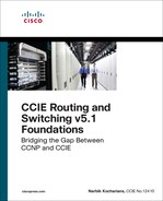
The simplest way to solve the mapping problem between the NBMA address (the “outside” address) and the tunnel IP address is to use static mappings. However, this is normally not done because it kind of removes the dynamic part of DMVPN. Let’s explore the concept here because it very clearly illustrates what we are trying to do. Let’s say you have the very simple topology outline shown in Figure 5-1. Let’s explore almost every aspect of the static method so we can compare it more analytically to the dynamic method in the next lab.
Task 1
SW1 represents the Internet. Configure a static default route on each router pointing to the appropriate interface on SW1. If this configuration is performed correctly, these routers should be able to ping and have reachability to the F0/0 interfaces of all routers in this topology. The switch interface to which the routers are connected should have “.10” in the host portion of the IP address for that subnet.
Let’s configure SW1’s interfaces for these routers. Because SW1 represents the Internet, the IP addresses in the following configuration should be made the default gateway on the routers.
On SW1:
SW1(config)# interface range FastEthernet0/1-4
SW1(config-if-range)# no switchport
SW1(config)# interface FastEthernet0/1
SW1(config-if)# ip address 192.1.1.10 255.255.255.0
SW1(config-if)# no shutdown
SW1(config)# interface FastEthernet0/2
SW1(config-if)# ip address 192.1.2.10 255.255.255.0
SW1(config-if)# no shutdown
SW1(config)# interface FastEthernet0/3
SW1(config-if)# ip address 192.1.3.10 255.255.255.0
SW1(config-if)# no shutdown
SW1(config)# interface FastEthernet0/4
SW1(config-if)# ip address 192.1.4.10 255.255.255.0
SW1(config-if)# no shutdown
Let’s not forget to enable ip routing; otherwise, the switch will not be able to route from one subnet to another:
SW1(config)# ip routing
Let’s configure the routers:
On R1:
R1(config)# interface FastEthernet0/0
R1(config-if)# ip address 192.1.1.1 255.255.255.0
R1(config-if)# no shutdown
R1(config)# ip route 0.0.0.0 0.0.0.0 192.1.1.10
On R2:
R2(config)# interface FastEthernet0/0
R2(config-if)# ip address 192.1.2.2 255.255.255.0
R2(config-if)# no shutdown
R2(config)# ip route 0.0.0.0 0.0.0.0 192.1.2.10
On R3:
R3(config)# interface FastEthernet0/0
R3(config-if)# ip address 192.1.3.3 255.255.255.0
R3(config-if)# no shutdown
R3(config)# ip route 0.0.0.0 0.0.0.0 192.1.3.10
On R4:
R4(config)# interface FastEthernet0/0
R4(config-if)# ip address 192.1.4.4 255.255.255.0
R4(config-if)# no shutdown
R4(config)# ip route 0.0.0.0 0.0.0.0 192.1.4.10
Now let’s verify the configuration:
On R1:
R1# ping 192.1.2.2
Type escape sequence to abort.
Sending 5, 100-byte ICMP Echos to 192.1.2.2, timeout is 2 seconds:
!!!!!
Success rate is 100 percent (5/5), round-trip min/avg/max = 1/2/4 ms
R1# ping 192.1.3.3
Type escape sequence to abort.
Sending 5, 100-byte ICMP Echos to 192.1.3.3, timeout is 2 seconds:
!!!!!
Success rate is 100 percent (5/5), round-trip min/avg/max = 1/2/4 ms
R1# ping 192.1.4.4
Type escape sequence to abort.
Sending 5, 100-byte ICMP Echos to 192.1.4.4, timeout is 2 seconds:
!!!!!
Success rate is 100 percent (5/5), round-trip min/avg/max = 1/2/4 ms
On R2:
R2# ping 192.1.1.1
Type escape sequence to abort.
Sending 5, 100-byte ICMP Echos to 192.1.1.1, timeout is 2 seconds:
!!!!!
Success rate is 100 percent (5/5), round-trip min/avg/max = 1/2/4 ms
R2# ping 192.1.3.3
Type escape sequence to abort.
Sending 5, 100-byte ICMP Echos to 192.1.3.3, timeout is 2 seconds:
!!!!!
Success rate is 100 percent (5/5), round-trip min/avg/max = 1/2/4 ms
R2# ping 192.1.4.4
Type escape sequence to abort.
Sending 5, 100-byte ICMP Echos to 192.1.4.4, timeout is 2 seconds:
!!!!!
Success rate is 100 percent (5/5), round-trip min/avg/max = 1/1/4 ms
Task 2
Configure DMVPN Phase 1 such that R1 is the hub and R2, R3, and R4 are the spokes. You should use 10.1.1.x/24, where x is the router number. If this configuration is performed correctly, these routers should have reachability to all tunnel endpoints. You should configure static mapping to accomplish this task.
DMVPN is a combination of mGRE, the Next-Hop Resolution Protocol (NHRP), and IPSec (optional). DMVPN can be implemented as Phase 1, Phase 2, or Phase 3.
There are two GRE flavors:
![]() GRE
GRE
![]() mGRE
mGRE
GRE, which is a point-to-point logical link, is configured with a tunnel source and tunnel destination. The tunnel source can either be an IP address or an interface. When a tunnel destination is configured, it ties the tunnel to a specific endpoint. This makes a GRE tunnel a point-to-point tunnel. If there are 200 endpoints, each endpoint would need to configure 199 GRE tunnels.
With Multipoint Generic Routing Encapsulation (mGRE), the configuration includes the tunnel source and tunnel mode. The tunnel destination is not configured. Therefore, the tunnel can have many endpoints, and only a single tunnel interface is utilized. The endpoints can be configured as a GRE tunnel or an mGRE tunnel.
But what if the spokes need to communicate with each other? Especially with the NBMA nature of mGRE? How would we accomplish that?
If a spoke needs to communicate with another spoke in a hub-and-spoke Frame Relay network, a Frame Relay mapping needs to be configured. Is there a mapping that we need to configure in mGRE?
Well, mGRE does not have a mapping capability. This is why another protocol is used. That protocol is called the Next-Hop Resolution Protocol (NHRP) and is defined in RFC 2332. It provides Layer 2 address resolution and a caching service, very much like ARP and inverse ARP.
NHRP is used by the spokes connected to an NBMA network to determine the NBMA IP address of the next-hop router. With NHRP, you can map a tunnel IP address to an NBMA IP address either statically or dynamically. The NBMA IP address is the IP address acquired from the service provider. The tunnel IP address is the IP address that you assigned to the tunnel interface, typically using RFC 1918 addressing.
In NHRP, a router is configured either as an NHRP client (NHC) or an NHRP server (NHS). The NHS acts as a mapping agent and stores all registered mappings performed by the NHC. The NHS can reply to the queries made by NHCs. NHCs send a query to the NHS if they need to communicate with another NHC.
NHRP is like the Address Resolution Protocol (ARP). Why is it like ARP? Because it allows NHCs to dynamically register their NBMA-IP-address-to-tunnel-IP-address mapping. This allows the NHCs to join the NBMA network without the NHS needing to be reconfigured. This means that when a new NHC is added to the NBMA network, none of the NHCs or the NHSs need to be reconfigured.
Let’s look at a scenario where the NHC has a dynamic physical IP address or the NHC is behind a network address translation (NAT) device. How would you configure the NHS and what IP addresses are you going to use for the NHCs?
This is the reason why dynamic registration and queries are very useful. In these scenarios, it is almost impossible to preconfigure the logical tunnel IP address to the physical NBMA IP address mapping for the NHCs on the NHS. NHRP is a resolution protocol that allows the NHCs to dynamically discover the logical-IP-address-to- physical-IP-address mapping for other NHCs within the same NBMA network.
Without this discovery, packets must traverse through the hub to reach other spokes. This can negatively impact the CPU and the bandwidth of the hub router.
There are three phases in DMVPN: Phase 1, Phase 2, and Phase 3. Here are some important points to remember about DMVPN Phase 1:
![]() mGRE is configured on the hub, and GRE is configured on the spokes.
mGRE is configured on the hub, and GRE is configured on the spokes.
![]() Multicast or unicast traffic can only flow between the hub and the spokes, not from spoke to spoke.
Multicast or unicast traffic can only flow between the hub and the spokes, not from spoke to spoke.
![]() This can be configured statically, or the NHCs (spokes) can register themselves dynamically with the NHS (the hub).
This can be configured statically, or the NHCs (spokes) can register themselves dynamically with the NHS (the hub).
Let’s configure R1 (the hub router) with static mappings.
The tunnel configuration on the hub, whether static or dynamic, can be broken down into two configuration steps. In the first step, the mGRE tunnel is configured. This step uses three configuration commands: the IP address of the tunnel, the tunnel source, and the tunnel mode, as shown here:
On R1:
R1(config)# interface tunnel 1
R1(config-if)# ip address 10.1.1.1 255.255.255.0
R1(config-if)# tunnel source 192.1.1.1
R1(config-if)# tunnel mode gre multipoint
In the second step, NHRP is configured. This configuration uses two NHRP configuration commands: the NHRP network ID (which enables NHRP on that tunnel interface) and the NHRP mapping that maps the tunnel IP address to the physical IP address (NBMA IP address) of the spoke(s). This needs to be done for each spoke. An optional third NHRP configuration command allows the mapping of multicast to the physical IP address of the spokes. This enables multicasting and allows the Interior Gateway Protocols (IGPs) to use multicasting over the tunnel interface. (Doesn’t this remind you of the Frame Relay days with the Broadcast keyword at the end of the frame-relay map statement?) In this task, the mapping of multicast to the NBMA IP address is not configured.
R1(config-if)# ip nhrp network-id 111
R1(config-if)# ip nhrp map 10.1.1.2 192.1.2.2
R1(config-if)# ip nhrp map 10.1.1.3 192.1.3.3
R1(config-if)# ip nhrp map 10.1.1.4 192.1.4.4
Let’s verify the configuration:
R1# show ip nhrp
10.1.1.2/32 via 10.1.1.2
Tunnel1 created 00:05:20, never expire
Type: static, Flags:
NBMA address: 192.1.2.2
10.1.1.3/32 via 10.1.1.3
Tunnel1 created 00:05:12, never expire
Type: static, Flags:
NBMA address: 192.1.3.3
10.1.1.4/32 via 10.1.1.4
Tunnel1 created 00:05:05, never expire
Type: static, Flags:
NBMA address: 192.1.4.4
In the DMVPN Phase 1 configuration on the spokes, the tunnels should be configured as point-to-point GRE tunnels. The configuration includes the tunnel source and the tunnel destination. Because the tunnel destination is configured, it ties that tunnel to that destination only. This makes the tunnel a point-to-point tunnel and not a multipoint tunnel. Once the tunnel commands are configured, the next step is to configure NHRP. In this configuration on the spokes, NHRP is enabled first and then a single mapping is configured for the hub’s tunnel IP address:
On R2:
R2(config)# interface tunnel 1
R2(config-if)# ip address 10.1.1.2 255.255.255.0
R2(config-if)# tunnel source 192.1.2.2
R2(config-if)# tunnel destination 192.1.1.1
R2(config-if)# ip nhrp network-id 222
R2(config-if)# ip nhrp map 10.1.1.1 192.1.1.1
Let’s verify the configuration:
R2# show ip nhrp
10.1.1.1/32 via 10.1.1.1
Tunnel1 created 00:04:03, never expire
Type: static, Flags:
NBMA address: 192.1.1.1
On R3:
R3(config)# interface tunnel 1
R3(config-if)# ip address 10.1.1.3 255.255.255.0
R3(config-if)# tunnel source FastEthernet0/0
R3(config-if)# tunnel destination 192.1.1.1
R3(config-if)# ip nhrp network-id 333
R3(config-if)# ip nhrp map 10.1.1.1 192.1.1.1
On R4:
R4(config)# interface tunnel 1
R4(config-if)# ip address 10.1.1.4 255.255.255.0
R4(config-if)# tunnel source FastEthernet0/0
R4(config-if)# tunnel destination 192.1.1.1
R4(config-if)# ip nhrp network-id 444
R4(config-if)# ip nhrp map 10.1.1.1 192.1.1.1
Now we can test the configuration:
On R1:
R1# ping 10.1.1.2
Type escape sequence to abort.
Sending 5, 100-byte ICMP Echos to 10.1.1.2, timeout is 2 seconds:
!!!!!
Success rate is 100 percent (5/5), round-trip min/avg/max = 1/3/4 ms
R1# ping 10.1.1.3
Type escape sequence to abort.
Sending 5, 100-byte ICMP Echos to 10.1.1.3, timeout is 2 seconds:
!!!!!
Success rate is 100 percent (5/5), round-trip min/avg/max = 1/3/4 ms
R1# ping 10.1.1.4
Type escape sequence to abort.
Sending 5, 100-byte ICMP Echos to 10.1.1.4, timeout is 2 seconds:
!!!!!
Success rate is 100 percent (5/5), round-trip min/avg/max = 1/3/4 ms
On R2:
R2# ping 10.1.1.1
Type escape sequence to abort.
Sending 5, 100-byte ICMP Echos to 10.1.1.1, timeout is 2 seconds:
!!!!!
Success rate is 100 percent (5/5), round-trip min/avg/max = 1/2/4 ms
R2# ping 10.1.1.3
Type escape sequence to abort.
Sending 5, 100-byte ICMP Echos to 10.1.1.3, timeout is 2 seconds:
!!!!!
Success rate is 100 percent (5/5), round-trip min/avg/max = 1/3/4 ms
R2# ping 10.1.1.4
Type escape sequence to abort.
Sending 5, 100-byte ICMP Echos to 10.1.1.4, timeout is 2 seconds:
!!!!!
Success rate is 100 percent (5/5), round-trip min/avg/max = 1/3/4 ms
To see the traffic path between the spokes:
R2# traceroute 10.1.1.3
Type escape sequence to abort.
Tracing the route to 10.1.1.3
VRF info: (vrf in name/id, vrf out name/id)
1 10.1.1.1 4 msec 4 msec 4 msec
2 10.1.1.3 0 msec * 0 msec
R2# traceroute 10.1.1.4
Type escape sequence to abort.
Tracing the route to 10.1.1.4
VRF info: (vrf in name/id, vrf out name/id)
1 10.1.1.1 4 msec 4 msec 0 msec
2 10.1.1.4 4 msec * 0 msec
On R3:
R3# ping 10.1.1.4
Type escape sequence to abort.
Sending 5, 100-byte ICMP Echos to 10.1.1.4, timeout is 2 seconds:
!!!!!
Success rate is 100 percent (5/5), round-trip min/avg/max = 1/2/4 ms
R3# traceroute 10.1.1.4
Type escape sequence to abort.
Tracing the route to 10.1.1.4
VRF info: (vrf in name/id, vrf out name/id)
1 10.1.1.1 0 msec 4 msec 4 msec
2 10.1.1.4 0 msec * 0 msec
Because the spokes are configured in a point-to-point manner, there is no need to map multicast traffic to the NBMA IP address of a given endpoint.
Erase the startup configuration of the routers and the switch and reload them before proceeding to the next lab.
Lab 5-2: DMVPN Phase 1 Using Dynamic Mapping
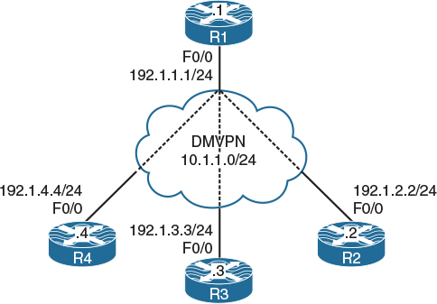
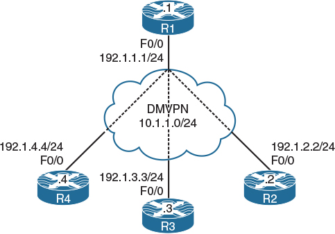
Figure 5-2 DMVPN Phase 1 Using Dynamic Mapping
Task 1
In Figure 5.2, we see the topology we will use in this lab. Hidden in the figure we see a cloud, and in this lab that cloud is a switch named SW1. SW1 represents the Internet; configure a static default route on each router pointing to the appropriate interface on SW1. If this configuration is performed correctly, these routers should be able to ping and have reachability to the F0/0 interfaces of all routers in this topology. The switch interface to which the routers are connected should have “.10” in the host portion of the IP address for that subnet.
Let’s configure SW1’s interfaces for these routers. Because in this lab SW1 represents the Internet, the IP addresses in the following configuration should be set as the default gateway on the routers.
On SW1:
SW1(config)# interface range FastEthernet0/1-4
SW1(config-if-range)# no switchport
SW1(config)# interface FastEthernet0/1
SW1(config-if)# ip address 192.1.1.10 255.255.255.0
SW1(config-if)# no shutdown
SW1(config)# interface FastEthernet0/2
SW1(config-if)# ip address 192.1.2.10 255.255.255.0
SW1(config-if)# no shutdown
SW1(config)# interface FastEthernet0/3
SW1(config-if)# ip address 192.1.3.10 255.255.255.0
SW1(config-if)# no shutdown
SW1(config)# interface FastEthernet0/4
SW1(config-if)# ip address 192.1.4.10 255.255.255.0
SW1(config-if)# no shutdown
Let’s not forget to enable ip routing; otherwise, the switch will not be able to route from one subnet to another:
SW1(config)# ip routing
Let’s configure the routers:
On R1:
R1(config)# interface FastEthernet0/0
R1(config-if)# ip address 192.1.1.1 255.255.255.0
R1(config-if)# no shutdown
R1(config)# ip route 0.0.0.0 0.0.0.0 192.1.1.10
On R2:
R2(config)# interface FastEthernet0/0
R2(config-if)# ip address 192.1.2.2 255.255.255.0
R2(config-if)# no shut
R2(config)# ip route 0.0.0.0 0.0.0.0 192.1.2.10
On R3:
R3(config)# interface FastEthernet0/0
R3(config-if)# ip address 192.1.3.3 255.255.255.0
R3(config-if)# no shutdown
R3(config)# ip route 0.0.0.0 0.0.0.0 192.1.3.10
On R4:
R4(config)# interface FastEthernet0/0
R4(config-if)# ip address 192.1.4.4 255.255.255.0
R4(config-if)# no shutdown
R4(config)# ip route 0.0.0.0 0.0.0.0 192.1.4.10
Now let’s verify the configuration:
On R1:
R1# ping 192.1.2.2
Type escape sequence to abort.
Sending 5, 100-byte ICMP Echos to 192.1.2.2, timeout is 2 seconds:
!!!!!
Success rate is 100 percent (5/5), round-trip min/avg/max = 1/2/4 ms
R1# ping 192.1.3.3
Type escape sequence to abort.
Sending 5, 100-byte ICMP Echos to 192.1.3.3, timeout is 2 seconds:
!!!!!
Success rate is 100 percent (5/5), round-trip min/avg/max = 1/2/4 ms
R1# ping 192.1.4.4
Type escape sequence to abort.
Sending 5, 100-byte ICMP Echos to 192.1.4.4, timeout is 2 seconds:
!!!!!
Success rate is 100 percent (5/5), round-trip min/avg/max = 1/2/4 ms
On R2:
R2# ping 192.1.1.1
Type escape sequence to abort.
Sending 5, 100-byte ICMP Echos to 192.1.1.1, timeout is 2 seconds:
!!!!!
Success rate is 100 percent (5/5), round-trip min/avg/max = 1/2/4 ms
R2# ping 192.1.3.3
Type escape sequence to abort.
Sending 5, 100-byte ICMP Echos to 192.1.3.3, timeout is 2 seconds:
!!!!!
Success rate is 100 percent (5/5), round-trip min/avg/max = 1/2/4 ms
R2# ping 192.1.4.4
Type escape sequence to abort.
Sending 5, 100-byte ICMP Echos to 192.1.4.4, timeout is 2 seconds:
!!!!!
Success rate is 100 percent (5/5), round-trip min/avg/max = 1/1/4 ms
Task 2
Configure DMVPN Phase 1 such that R1 is the hub and R2, R3, and R4 are the spokes. You should use 10.1.1.x/24, where x is the router number. If this configuration is performed correctly, these routers should have reachability to all tunnel endpoints. You should not configure static mappings on the hub router to accomplish this task.
Because the task refers to DMVPN Phase 1, you know that the hub router must be configured in a multipoint manner and the spokes should be configured in a point-to-point manner. The task also specifies that the hub router should not be configured with static mappings. This means that the hub should be configured such that the mappings are performed dynamically. This configuration is more scalable than configuring the hub with static mappings. If the hub is configured with static mappings for each spoke, a newly added spoke will require some configuration on the hub. If the mappings are performed dynamically, the spokes can be added dynamically without any configuration performed on the hub. How does that work?
When a spoke router initially connects to the DMVPN network, it registers its tunnel-IP-address-to-NBMA-IP-address mapping with the hub router. The hub router will acknowledge the registration by sending back the registration message that was initiated by the spoke with a success code. This registration enables the mGRE interface on the hub router to build a dynamic GRE tunnel back to the registering spoke router. This means that the spoke routers must be configured with the tunnel IP address of the hub; otherwise, they won’t know where to go to register their tunnel-IP-address-to-NBMA-IP-address mapping.
Let’s configure the routers, starting with the hub (R1). Remember that this configuration should be done in two steps. In the first step, the tunnel source and tunnel mode are configured:
On R1:
R1(config)# interface tunnel 1
R1(config-if)# ip address 10.1.1.1 255.255.255.0
R1(config-if)# tunnel source 192.1.1.1
R1(config-if)# tunnel mode gre multipoint
In the second step, NHRP is configured. First, the NHRP network ID is configured, which enables NHRP on that tunnel interface. The NHRP mapping should then be configured. This mapping can be configured dynamically or statically. The previous lab demonstrated the configuration of static mapping. In this lab, the configuration of dynamic mapping is demonstrated. In a dynamic mapping configuration, nothing else is done. As long as NHRP is enabled on that interface, the mappings will occur dynamically. Let’s configure the routers and verify.
R1(config-if)# ip nhrp network-id 111
Since in DMVPN Phase 1 configuration the spoke routers should be configured as “point to point,” the configuration includes the tunnel source and the tunnel destination. Because the tunnel destination is configured, it ties that tunnel to that destination only. This makes the tunnel a point-to-point tunnel and not a multipoint tunnel. Once the tunnel commands are configured, the next step to configure NHRP. To configure NHRP dynamically on the spokes, first enable NHRP and then configure the NHS.
Note Because the tunnel on the spoke routers (R2, R3, and R4) is configured in a point-to-point manner, there is no need to configure an NHRP mapping for the NHS’s IP address.
On R2:
R2(config)# interface tunnel 1
R2(config-if)# ip address 10.1.1.2 255.255.255.0
R2(config-if)# tunnel source FastEthernet0/0
R2(config-if)# tunnel destination 192.1.1.1
R2(config-if)# ip nhrp network-id 222
R2(config-if)# ip nhrp nhs 10.1.1.1
Let’s verify the configuration:
On R1:
R1# show ip nhrp
10.1.1.2/32 via 10.1.1.2
Tunnel1 created 00:01:05, expire 01:58:54
Type: dynamic, Flags: unique registered
NBMA address: 192.1.2.2
You can see that once R2 was connected to the DMVPN network, the hub router (R1) created a dynamic entry for R2. Let’s configure the other spoke routers:
On R3:
R3(config)# interface tunnel 1
R3(config-if)# ip address 10.1.1.3 255.255.255.0
R3(config-if)# tunnel source FastEthernet0/0
R3(config-if)# tunnel destination 192.1.1.1
R3(config-if)# ip nhrp network-id 333
R3(config-if)# ip nhrp nhs 10.1.1.1
On R4:
R4(config)# interface tunnel 1
R4(config-if)# ip address 10.1.1.4 255.255.255.0
R4(config-if)# tunnel source FastEthernet0/0
R4(config-if)# tunnel destination 192.1.1.1
R4(config-if)# ip nhrp network-id 444
R4(config-if)# ip nhrp nhs 10.1.1.1
Let’s verify the configuration:
On R1:
R1# show ip nhrp
10.1.1.2/32 via 10.1.1.2
Tunnel1 created 00:05:53, expire 01:54:06
Type: dynamic, Flags: unique registered
NBMA address: 192.1.2.2
10.1.1.3/32 via 10.1.1.3
Tunnel1 created 00:02:24, expire 01:57:35
Type: dynamic, Flags: unique registered
NBMA address: 192.1.3.3
10.1.1.4/32 via 10.1.1.4
Tunnel1 created 00:00:21, expire 01:59:38
Type: dynamic, Flags: unique registered
NBMA address: 192.1.4.4
Now let’s test the configuration:
On R1:
R1# ping 10.1.1.2
Type escape sequence to abort.
Sending 5, 100-byte ICMP Echos to 10.1.1.2, timeout is 2 seconds:
!!!!!
Success rate is 100 percent (5/5), round-trip min/avg/max = 1/3/4 ms
R1# ping 10.1.1.3
Type escape sequence to abort.
Sending 5, 100-byte ICMP Echos to 10.1.1.3, timeout is 2 seconds:
!!!!!
Success rate is 100 percent (5/5), round-trip min/avg/max = 1/2/4 ms
R1# ping 10.1.1.4
Type escape sequence to abort.
Sending 5, 100-byte ICMP Echos to 10.1.1.4, timeout is 2 seconds:
!!!!!
Success rate is 100 percent (5/5), round-trip min/avg/max = 1/3/4 ms
On R3:
R3# ping 10.1.1.1
Type escape sequence to abort.
Sending 5, 100-byte ICMP Echos to 10.1.1.1, timeout is 2 seconds:
!!!!!
Success rate is 100 percent (5/5), round-trip min/avg/max = 1/3/4 ms
R3# ping 10.1.1.2
Type escape sequence to abort.
Sending 5, 100-byte ICMP Echos to 10.1.1.2, timeout is 2 seconds:
!!!!!
Success rate is 100 percent (5/5), round-trip min/avg/max = 1/2/4 ms
R3# ping 10.1.1.4
Type escape sequence to abort.
Sending 5, 100-byte ICMP Echos to 10.1.1.4, timeout is 2 seconds:
!!!!!
Success rate is 100 percent (5/5), round-trip min/avg/max = 1/2/4 ms
R3# traceroute 10.1.1.2 numeric
Type escape sequence to abort.
Tracing the route to 10.1.1.2
VRF info: (vrf in name/id, vrf out name/id)
1 10.1.1.1 0 msec 4 msec 4 msec
2 10.1.1.2 4 msec * 0 msec
You can see that in DMVPN Phase 1, no matter the configuration (static mapping or dynamic mapping), the spokes will go through the hub to connect to the other spokes.
Erase the startup configuration of the routers and the switch and reload them before proceeding to the next lab.
Lab 5-3: DMVPN Phase 2 Using Static Mapping
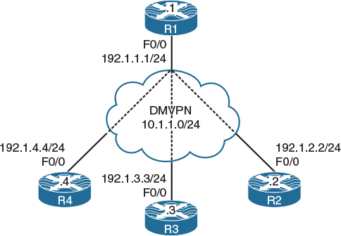
Figure 5-3 DMVPN Phase 2 Using Static Mapping
In Figure 5.3, we see the topology we will use in this lab. To allow the dynamic spoke-to-spoke tunnels to form, you need to change the spokes to multipoint tunnels. As you do that, you need to make sure that you also add a static entry for the hub, because without that entry, the NHRP registration cannot be sent. The question then becomes, how does a spoke learn the NHRP mapping of another spoke? A system of requests and replies are used where a spoke sends a request for a particular spoke that it wants to send traffic to. It then gets a reply from the spoke in question. The process looks something like the following:
1. Spoke 1 forwards a packet with a next hop that is another spoke, spoke 2. There is no NHRP map entry for this spoke, so an NHRP resolution request is sent to the hub.
2. The request from spoke 1 contains the tunnel IP address of spoke 2. The hub relays the request to spoke 2.
3. Spoke 2 receives the request, adds its own address mapping to it, and sends it as an NHRP reply directly to spoke 1.
4. Spoke 2 then sends its own request to the hub, which relays it to spoke 1.
5. Spoke 1 receives the request from spoke 2 via the hub and replies by adding its own mapping to the packet and sending it directly to spoke 2.
6. Technically, the requests themselves provide enough information to build a spoke-to-spoke tunnel, but the replies accomplish two things. They acknowledge to the other spoke that the request was received and also verify that spoke-to-spoke NBMA reachability exists.
This phase of DMVPN deployment has some restrictions:
![]() Summarization is not allowed on the hub.
Summarization is not allowed on the hub.
![]() Default routing is not allowed on the hub.
Default routing is not allowed on the hub.
![]() The spokes must always maintain next-hop reachability.
The spokes must always maintain next-hop reachability.
Task 1
SW1 represents the Internet. Configure a static default route on each router pointing to the appropriate interface on SW1. If this configuration is performed correctly, these routers should be able to ping and have reachability to the F0/0 interfaces of all routers in this topology. The switch interface to which the routers are connected should have “.10” in the host portion of the IP address for that subnet.
Let’s configure SW1’s interfaces for these routers. Since in this lab SW1 represents the Internet, the IP addresses in the following configuration should be set as the default gateway on the routers:
On SW1:
SW1(config)# interface range FastEthernet0/1-4
SW1(config-if-range)# no switchport
SW1(config)# interface FastEthernet0/1
SW1(config-if)# ip address 192.1.1.10 255.255.255.0
SW1(config-if)# no shutdown
SW1(config)# interface FastEthernet0/2
SW1(config-if)# ip address 192.1.2.10 255.255.255.0
SW1(config-if)# no shutdown
SW1(config)# interface FastEthernet0/3
SW1(config-if)# ip address 192.1.3.10 255.255.255.0
SW1(config-if)# no shutdown
SW1(config)# interface FastEthernet0/4
SW1(config-if)# ip address 192.1.4.10 255.255.255.0
SW1(config-if)# no shutdown
Let’s not forget to enable ip routing; otherwise, the switch will not be able to route from one subnet to another:
SW1(config)# ip routing
Let’s configure the routers:
On R1:
R1(config)# interface FastEthernet0/0
R1(config-if)# ip address 192.1.1.1 255.255.255.0
R1(config-if)# no shutdown
R1(config)# ip route 0.0.0.0 0.0.0.0 192.1.1.10
On R2:
R2(config)# interface FastEthernet0/0
R2(config-if)# ip address 192.1.2.2 255.255.255.0
R2(config-if)# no shutdown
R2(config)# ip route 0.0.0.0 0.0.0.0 192.1.2.10
On R3:
R3(config)# interface FastEthernet0/0
R3(config-if)# ip address 192.1.3.3 255.255.255.0
R3(config-if)# no shutdown
R3(config)# ip route 0.0.0.0 0.0.0.0 192.1.3.10
On R4:
R4(config)# interface FastEthernet0/0
R4(config-if)# ip address 192.1.4.4 255.255.255.0
R4(config-if)# no shutdown
R4(config)# ip route 0.0.0.0 0.0.0.0 192.1.4.10
Now let’s verify the configuration:
On R1:
R1# ping 192.1.2.2
Type escape sequence to abort.
Sending 5, 100-byte ICMP Echos to 192.1.2.2, timeout is 2 seconds:
!!!!!
Success rate is 100 percent (5/5), round-trip min/avg/max = 1/2/4 ms
R1# ping 192.1.3.3
Type escape sequence to abort.
Sending 5, 100-byte ICMP Echos to 192.1.3.3, timeout is 2 seconds:
!!!!!
Success rate is 100 percent (5/5), round-trip min/avg/max = 1/2/4 ms
R1# ping 192.1.4.4
Type escape sequence to abort.
Sending 5, 100-byte ICMP Echos to 192.1.4.4, timeout is 2 seconds:
!!!!!
Success rate is 100 percent (5/5), round-trip min/avg/max = 1/2/4 ms
On R2:
R2# ping 192.1.1.1
Type escape sequence to abort.
Sending 5, 100-byte ICMP Echos to 192.1.1.1, timeout is 2 seconds:
!!!!!
Success rate is 100 percent (5/5), round-trip min/avg/max = 1/2/4 ms
R2# ping 192.1.3.3
Type escape sequence to abort.
Sending 5, 100-byte ICMP Echos to 192.1.3.3, timeout is 2 seconds:
!!!!!
Success rate is 100 percent (5/5), round-trip min/avg/max = 1/2/4 ms
R2# ping 192.1.4.4
Type escape sequence to abort.
Sending 5, 100-byte ICMP Echos to 192.1.4.4, timeout is 2 seconds:
!!!!!
Success rate is 100 percent (5/5), round-trip min/avg/max = 1/1/4 ms
Task 2
Configure DMVPN Phase 2 such that R1 is the hub and R2, R3, and R4 are the spokes. You should use 10.1.1.x/24, where x is the router number. If this configuration is performed correctly, these routers should have reachability to all tunnel endpoints. You should configure static mappings on the hub router to accomplish this task.
Since the task refers to DMVPN Phase 2, the hub and all the spokes are configured with multipoint GRE tunnels. In this phase, the spokes have reachability to the other spokes directly.
Let’s configure the routers:
On R1:
R1(config)# interface tunnel 1
R1(config-if)# ip address 10.1.1.1 255.255.255.0
R1(config-if)# tunnel source 192.1.1.1
R1(config-if)# tunnel mode gre multipoint
R1(config-if)# ip nhrp network-id 111
R1(config-if)# ip nhrp map 10.1.1.2 192.1.2.2
On R1:
R4(config-if)# ip nhrp map 10.1.1.3 192.1.3.3
R4(config-if)# ip nhrp map 10.1.1.4 192.1.4.4
On R2:
R2(config)# interface tunnel 1
R2(config-if)# ip address 10.1.1.2 255.255.255.0
R2(config-if)# tunnel source FastEthernet0/0
R2(config-if)# tunnel mode gre multipoint
R2(config-if)# ip nhrp network-id 222
R2(config-if)# ip nhrp map 10.1.1.1 192.1.1.1
R2(config-if)# ip nhrp map 10.1.1.3 192.1.3.3
R2(config-if)# ip nhrp map 10.1.1.4 192.1.4.4
On R3:
R3(config)# interface tunnel 1
R3(config-if)# ip address 10.1.1.3 255.255.255.0
R3(config-if)# tunnel source FastEthernet0/0
R3(config-if)# tunnel mode gre multipoint
R3(config-if)# ip nhrp network-id 333
R3(config-if)# ip nhrp map 10.1.1.1 192.1.1.1
R3(config-if)# ip nhrp map 10.1.1.2 192.1.2.2
R3(config-if)# ip nhrp map 10.1.1.4 192.1.4.4
On R4:
R4(config)# interface tunnel 1
R4(config-if)# ip address 10.1.1.4 255.255.255.0
R4(config-if)# tunnel source FastEthernet0/0
R4(config-if)# tunnel mode gre multipoint
R4(config-if)# ip nhrp network-id 444
R4(config-if)# ip nhrp map 10.1.1.1 192.1.1.1
R4(config-if)# ip nhrp map 10.1.1.2 192.1.2.2
R4(config-if)# ip nhrp map 10.1.1.3 192.1.3.3
Let’s verify the configuration:
On R1:
R1# show ip nhrp
10.1.1.2/32 via 10.1.1.2
Tunnel1 created 00:19:16, never expire
Type: static, Flags: used
NBMA address: 192.1.2.2
10.1.1.3/32 via 10.1.1.3
Tunnel1 created 00:19:08, never expire
Type: static, Flags:
NBMA address: 192.1.3.3
10.1.1.4/32 via 10.1.1.4
Tunnel1 created 00:01:09, never expire
Type: static, Flags:
NBMA address: 192.1.4.4
On R2:
R2# show ip nhrp
10.1.1.1/32 via 10.1.1.1
Tunnel1 created 00:15:34, never expire
Type: static, Flags: used
NBMA address: 192.1.1.1
10.1.1.3/32 via 10.1.1.3
Tunnel1 created 00:15:27, never expire
Type: static, Flags:
NBMA address: 192.1.3.3
10.1.1.4/32 via 10.1.1.4
Tunnel1 created 00:15:19, never expire
Type: static, Flags:
NBMA address: 192.1.4.4
On R3:
R3# show ip nhrp
10.1.1.1/32 via 10.1.1.1
Tunnel1 created 00:15:19, never expire
Type: static, Flags:
NBMA address: 192.1.1.1
10.1.1.2/32 via 10.1.1.2
Tunnel1 created 00:15:11, never expire
Type: static, Flags:
NBMA address: 192.1.2.2
10.1.1.4/32 via 10.1.1.4
Tunnel1 created 00:15:02, never expire
Type: static, Flags:
NBMA address: 192.1.4.4
On R4:
R4# show ip nhrp
10.1.1.1/32 via 10.1.1.1
Tunnel1 created 00:15:13, never expire
Type: static, Flags:
NBMA address: 192.1.1.1
10.1.1.2/32 via 10.1.1.2
Tunnel1 created 00:15:04, never expire
Type: static, Flags:
NBMA address: 192.1.2.2
10.1.1.3/32 via 10.1.1.3
Tunnel1 created 00:14:57, never expire
Type: static, Flags:
NBMA address: 192.1.3.3
Now let’s test the configuration:
On R1:
R1# ping 10.1.1.2
Type escape sequence to abort.
Sending 5, 100-byte ICMP Echos to 10.1.1.2, timeout is 2 seconds:
!!!!!
Success rate is 100 percent (5/5), round-trip min/avg/max = 1/3/4 ms
R1# ping 10.1.1.3
Type escape sequence to abort.
Sending 5, 100-byte ICMP Echos to 10.1.1.3, timeout is 2 seconds:
!!!!!
Success rate is 100 percent (5/5), round-trip min/avg/max = 1/2/4 ms
R1# ping 10.1.1.4
Type escape sequence to abort.
Sending 5, 100-byte ICMP Echos to 10.1.1.4, timeout is 2 seconds:
!!!!!
Success rate is 100 percent (5/5), round-trip min/avg/max = 1/3/4 ms
On R3:
R3# ping 10.1.1.1
Type escape sequence to abort.
Sending 5, 100-byte ICMP Echos to 10.1.1.1, timeout is 2 seconds:
!!!!!
Success rate is 100 percent (5/5), round-trip min/avg/max = 1/3/4 ms
R3# ping 10.1.1.2
Type escape sequence to abort.
Sending 5, 100-byte ICMP Echos to 10.1.1.2, timeout is 2 seconds:
!!!!!
Success rate is 100 percent (5/5), round-trip min/avg/max = 1/2/4 ms
R3# ping 10.1.1.4
Type escape sequence to abort.
Sending 5, 100-byte ICMP Echos to 10.1.1.4, timeout is 2 seconds:
!!!!!
Success rate is 100 percent (5/5), round-trip min/avg/max = 1/2/4 ms
R3# traceroute 10.1.1.2
Type escape sequence to abort.
Tracing the route to 10.1.1.2
VRF info: (vrf in name/id, vrf out name/id)
1 10.1.1.2 4 msec * 0 msec
You can see in DMVPN Phase 2 that the spokes can communicate with and reach other spokes directly.
Erase the startup configuration of the routers and the switch and reload them before proceeding to the next lab.
Lab 5-4: DMVPN Phase 2 Using Dynamic Mapping

Figure 5-4 DMVPN Phase 2 Using Dynamic Mapping
Task 1
In Figure 5.4, we see the topology we will use in this lab. Hidden in the figure we see a cloud, and in this lab that cloud is a switch named SW1. SW1 represents the Internet. Configure a static default route on each router pointing to the appropriate interface on SW1. If this configuration is performed correctly, these routers should be able to ping and have reachability to the F0/0 interfaces of all routers in this topology. The switch interface to which the routers are connected should have “.10” in the host portion of the IP address for the subnet.
Let’s configure SW1’s interfaces for these routers. Since in this lab SW1 represents the Internet, the IP addresses in the following configuration should be set as the default gateway on the routers:
On SW1:
SW1(config)# interface range FastEthernet0/1-4
SW1(config-if-range)# no switchport
SW1(config)# interface FastEthernet0/1
SW1(config-if)# ip address 192.1.1.10 255.255.255.0
SW1(config-if)# no shutdown
SW1(config)# interface FastEthernet0/2
SW1(config-if)# ip address 192.1.2.10 255.255.255.0
SW1(config-if)# no shutdown
SW1(config)# interface FastEthernet0/3
SW1(config-if)# ip address 192.1.3.10 255.255.255.0
SW1(config-if)# no shutdown
SW1(config)# interface FastEthernet0/4
SW1(config-if)# ip address 192.1.4.10 255.255.255.0
SW1(config-if)# no shutdown
Let’s not forget to enable ip routing; otherwise, the switch will not be able to route from one subnet to another:
SW1(config)# ip routing
Let’s configure the routers:
On R1:
R1(config)# interface FastEthernet0/0
R1(config-if)# ip address 192.1.1.1 255.255.255.0
R1(config-if)# no shutdown
R1(config)# ip route 0.0.0.0 0.0.0.0 192.1.1.10
On R2:
R2(config)# interface FastEthernet0/0
R2(config-if)# ip address 192.1.2.2 255.255.255.0
R2(config-if)# no shutdown
R2(config)# ip route 0.0.0.0 0.0.0.0 192.1.2.10
On R3:
R3(config)# interface FastEthernet0/0
R3(config-if)# ip address 192.1.3.3 255.255.255.0
R3(config-if)# no shutdown
R3(config)# ip route 0.0.0.0 0.0.0.0 192.1.3.10
On R4:
R4(config)# interface FastEthernet0/0
R4(config-if)# ip address 192.1.4.4 255.255.255.0
R4(config-if)# no shutdown
R4(config)# ip route 0.0.0.0 0.0.0.0 192.1.4.10
Let’s verify the configuration:
On R1:
R1# ping 192.1.2.2
Type escape sequence to abort.
Sending 5, 100-byte ICMP Echos to 192.1.2.2, timeout is 2 seconds:
!!!!!
Success rate is 100 percent (5/5), round-trip min/avg/max = 1/2/4 ms
R1# ping 192.1.3.3
Type escape sequence to abort.
Sending 5, 100-byte ICMP Echos to 192.1.3.3, timeout is 2 seconds:
!!!!!
Success rate is 100 percent (5/5), round-trip min/avg/max = 1/2/4 ms
R1# ping 192.1.4.4
Type escape sequence to abort.
Sending 5, 100-byte ICMP Echos to 192.1.4.4, timeout is 2 seconds:
!!!!!
Success rate is 100 percent (5/5), round-trip min/avg/max = 1/2/4 ms
On R2:
R2# ping 192.1.1.1
Type escape sequence to abort.
Sending 5, 100-byte ICMP Echos to 192.1.1.1, timeout is 2 seconds:
!!!!!
Success rate is 100 percent (5/5), round-trip min/avg/max = 1/2/4 ms
R2# ping 192.1.3.3
Type escape sequence to abort.
Sending 5, 100-byte ICMP Echos to 192.1.3.3, timeout is 2 seconds:
!!!!!
Success rate is 100 percent (5/5), round-trip min/avg/max = 1/2/4 ms
R2# ping 192.1.4.4
Type escape sequence to abort.
Sending 5, 100-byte ICMP Echos to 192.1.4.4, timeout is 2 seconds:
!!!!!
Success rate is 100 percent (5/5), round-trip min/avg/max = 1/1/4 ms
Task 2
Configure DMVPN Phase 2 such that R1 is the hub and R2, R3, and R4 are the spokes. You should use 10.1.1.x/24, where x is the router number. If this configuration is performed correctly, these routers should have reachability to all tunnel endpoints. You should not configure static mappings on the hub router to accomplish this task.
Since the task refers to DMVPN Phase 2, the hub and all the spokes are configured with multipoint GRE tunnels. In this phase, the spokes have reachability to the other spokes directly.
On R1:
R1(config)# interface tunnel 1
R1(config-if)# ip address 10.1.1.1 255.255.255.0
R1(config-if)# tunnel source 192.1.1.1
R1(config-if)# tunnel mode gre multipoint
R1(config-if)# ip nhrp network-id 111
The spokes are configured with a tunnel source, a tunnel mode, and an NHRP network ID. The configuration ip nhrp nhs identifies the NHRP next-hop server. The configuration ip nhrp map 10.1.1.1 192.1.1.1 maps the hub’s tunnel IP address to the hub’s NBMA IP address. If this mapping is not configured, the spokes won’t be able to communicate with the hub router. This mapping is needed because the spokes are configured with a multipoint GRE tunnel.
On R2:
R2(config)# interface tunnel 1
R2(config-if)# ip address 10.1.1.2 255.255.255.0
R2(config-if)# tunnel source FastEthernet0/0
R2(config-if)# tunnel mode gre multipoint
R2(config-if)# ip nhrp network-id 222
R2(config-if)# ip nhrp nhs 10.1.1.1
R2(config-if)# ip nhrp map 10.1.1.1 192.1.1.1
Before we configure R3, let’s enable debug nhrp packet and debug nhrp cache on both R1 and R3 and verify the output:
On R3:
R3(config)# interface tunnel 1
R3(config-if)# ip address 10.1.1.3 255.255.255.0
R3(config-if)# tunnel source FastEthernet0/0
R3(config-if)# tunnel mode gre multipoint
R3(config-if)# ip nhrp network-id 333
R3(config-if)# ip nhrp nhs 10.1.1.1
R3(config-if)# ip nhrp map 10.1.1.1 192.1.1.1
The following debug output was produced once the ip nhrp map 10.1.1.1 192.1.1.1 command was configured:
NHRP: Tunnel1: Cache add for target 10.1.1.1/32 next-hop 10.1.1.1
192.1.1.1
The following debug output sends a registration request to the NHS, which happened because we configured the NHS using the ip nhrp nhs 10.1.1.1 command:
NHRP: Send Registration Request via Tunnel1 vrf 0, packet size: 92
src: 10.1.1.3, dst: 10.1.1.1
On R1:
R1 received the registration request and added the entry to its cache.
NHRP: Receive Registration Request via Tunnel1 vrf 0, packet size: 92
(F) afn: IPv4(1), type: IP(800), hop: 255, ver: 1
shtl: 4(NSAP), sstl: 0(NSAP)
pktsz: 92 extoff: 52
(M) flags: "unique nat ", reqid: 65537
src NBMA: 192.1.2.2
src protocol: 10.1.1.2, dst protocol: 10.1.1.1
NHRP: Tunnel1: Cache update for target 10.1.1.2/32 next-hop 10.1.1.2
192.1.2.2
Let’s configure R4:
On R4:
R4(config)# interface tunnel 1
R4(config-if)# ip address 10.1.1.4 255.255.255.0
R4(config-if)# tunnel source FastEthernet0/0
R4(config-if)# tunnel mode gre multipoint
R4(config-if)# ip nhrp network-id 444
R4(config-if)# ip nhrp nhs 10.1.1.1
R4(config-if)# ip nhrp map 10.1.1.1 192.1.1.1
Now we can verify and test the configuration. Let’s start by looking at the existing NHRP cache:
R4# show ip nhrp
10.1.1.1/32 via 10.1.1.1
Tunnel1 created 00:00:24, never expire
Type: static, Flags: used
NBMA address: 192.1.1.1
The following traceroute should go through the hub router to reach 10.1.1.2, because this is the initial communication between the two spokes. R4 needs to send a resolution request to the hub router, R1. R1 receives the message and redirects that request to the destination spoke, R2. Because R4 includes its tunnel-IP-address-to-NBMA-IP-address mapping in the resolution request message, R2 caches the mapping information for R4 when it receives that message. R2 establishes a tunnel to R4 directly. When R4 receives the resolution message from R2, it caches the tunnel-IP-address-to-NBMA-IP-address mapping for R2. From that point on, it goes directly to R4.
R4# traceroute 10.1.1.2
Type escape sequence to abort.
Tracing the route to 10.1.1.2
VRF info: (vrf in name/id, vrf out name/id)
1 10.1.1.1 8 msec 0 msec 4 msec
2 10.1.1.2 8 msec * 0 msec
R4# show ip nhrp
10.1.1.1/32 via 10.1.1.1
Tunnel1 created 00:00:44, never expire
Type: static, Flags: used
NBMA address: 192.1.1.1
10.1.1.2/32 via 10.1.1.2
Tunnel1 created 00:00:07, expire 01:59:52
Type: dynamic, Flags: router used
NBMA address: 192.1.2.2
10.1.1.4/32 via 10.1.1.4
Tunnel1 created 00:00:07, expire 01:59:52
Type: dynamic, Flags: router unique local
NBMA address: 192.1.4.4
(no-socket)
You can see that in DMVPN Phase 2, the spokes can communicate with and reach other spokes directly.
Erase the startup configuration of the routers and the switch and reload them before proceeding to the next lab.
Lab 5-5: DMVPN Phase 3
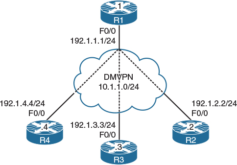
Figure 5-5 DMVPN Phase 3
In Figure 5.5, we see the topology we will use in this lab. Phase 3 is just like Phase 2 of mGRE tunnels on the hub and on the spokes of a DMVPN, but adding an NHRP redirect allows the data plane of spoke-to-spoke conversations to join the spokes directly without going through the hub, thus eliminating the requirement to conduct IP CEF (Cisco Express Forwarding) resolution.
NHRP Phase 3 allows the spokes to support NHRP resolution requests, meaning that the hub is not the only device that contains the NHRP database.
Operationally, the process follows these guidelines:
Step 1. The spokes register their mappings with the Hub. This allows the hub and spokes to dynamically discover and establish adjacencies. Then the routing information is exchanged. However, the hub is not obliged to preserve the information. We can summarize routes, given that they are sent to the spokes. One can even send a route-default to the spokes, which improves network scalability.
Step 2. The spokes receive routing information and fill their CEF tables. In this phase of DMVPN there should be no CEF invalid entries; they are all “complete.” They all point to the IP of the hub NBMA, so that all the first packets are CEF switches to the hub, and the invalid CEF no longer triggers the NHRP resolution.
Henceforth, the spoke-to-spoke communications are based on the packet NHRP Redirect message.
Step 3. A tunnel mGRE is configured for NHRP Redirect messages (the first major order for Phase 3), which is an operation similar to the ICMP redirect IP. When a router receives an incoming IP packet via the mGRE tunnel, which will be returning on the same interface, it sends a source Redirect NHRP. This message tells the source that the path is not optimal, and it should find a better way via the NHRP Resolution. This first package is still routed through the GDI.
Step 4. Now the spoke receives the NHRP Redirect. The router is thus sending an NHRP Request to the same destination IP, which is not the NHS (although the package always goes through there). The NHRP Request travels on all spokes until it finds the target. This is the normal operation of NHRP Request forwarding, which goes hop by hop.
Step 5. Now the spoke (not the NHS) has the resolution. Based on the IP source present in the payload package, it finds the corresponding spoke in its routing table. It uses the source NBMA IP router and returns an NHRP reply directly (without re-crossing the hub). The reply arrives on the source router, which then learns the IP NBMA its destination. Now, in addition to rewriting the NHRP table, the router rewrites the CEF entry.
The rewriting of the CEF is called NHRP Shortcut. Instead of having a CEF adjacency that triggers the NHRP Request, the CEF entry is rewritten when the NHRP Response is received. Simple.
Traffic is CEF switched at all times, and NHRP responses update the table of router CEF entries.
In summation:
![]() NHRP is needed for spoke registration to the hub.
NHRP is needed for spoke registration to the hub.
![]() NHRP is required for spoke-to-spoke resolution.
NHRP is required for spoke-to-spoke resolution.
![]() When traffic goes from a spoke to the hub, and the hub sees that the destination is reachable via another spoke, it sends an NHRP Redirect, which causes the spoke to install routes to each other.
When traffic goes from a spoke to the hub, and the hub sees that the destination is reachable via another spoke, it sends an NHRP Redirect, which causes the spoke to install routes to each other.
![]() A spoke-to-spoke tunnel is triggered by the hub via NHRP Redirect.
A spoke-to-spoke tunnel is triggered by the hub via NHRP Redirect.
![]() NHRP Resolution is done per true destination and not per next hop, as in Phase 2.
NHRP Resolution is done per true destination and not per next hop, as in Phase 2.
Unlike Phase 2, Phase 3 has far less restrictive behavior:
![]() Summarization is allowed on the hub.
Summarization is allowed on the hub.
![]() Default routing is allowed on the hub.
Default routing is allowed on the hub.
![]() Next-hop values on the spokes are always modified.
Next-hop values on the spokes are always modified.
We will explore these and other aspects of Phase 3 DMVPNs in the following tasks.
Task 1
SW1 represents the Internet. Configure a static default route on each router pointing to the appropriate interface on SW1. If this configuration is performed correctly, these routers should be able to ping and have reachability to the F0/0 interfaces of all routers in this topology. The switch interface to which the routers are connected should have “.10” in the host portion of the IP address for that subnet.
Let’s configure SW1’s interfaces for these routers. Because in this lab, SW1 represents the Internet, the IP addresses in the following configuration should be set as the default gateway on the routers:
On SW1:
SW1(config)# interface range FastEthernet0/1-4
SW1(config-if-range)# no switchport
SW1(config)# interface FastEthernet0/1
SW1(config-if)# ip address 192.1.1.10 255.255.255.0
SW1(config-if)# no shutdown
SW1(config)# interface FastEthernet0/2
SW1(config-if)# ip address 192.1.2.10 255.255.255.0
SW1(config-if)# no shutdown
SW1(config)# interface FastEthernet0/3
SW1(config-if)# ip address 192.1.3.10 255.255.255.0
SW1(config-if)# no shutdown
SW1(config)# interface FastEthernet0/4
SW1(config-if)# ip address 192.1.4.10 255.255.255.0
SW1(config-if)# no shutdown
Let’s not forget to enable ip routing; otherwise, the switch will not be able to route from one subnet to another:
SW1(config)# ip routing
Let’s configure the routers:
On R1:
R1(config)# interface FastEthernet0/0
R1(config-if)# ip address 192.1.1.1 255.255.255.0
R1(config-if)# no shutdown
R1(config)# ip route 0.0.0.0 0.0.0.0 192.1.1.10
On R2:
R2(config)# interface FastEthernet0/0
R2(config-if)# ip address 192.1.2.2 255.255.255.0
R2(config-if)# no shutdown
R2(config)# ip route 0.0.0.0 0.0.0.0 192.1.2.10
On R3:
R3(config)# interface FastEthernet0/0
R3(config-if)# ip address 192.1.3.3 255.255.255.0
R3(config-if)# no shutdown
R3(config)# ip route 0.0.0.0 0.0.0.0 192.1.3.10
On R4:
R4(config)# interface FastEthernet0/0
R4(config-if)# ip address 192.1.4.4 255.255.255.0
R4(config-if)# no shutdown
R4(config)# ip route 0.0.0.0 0.0.0.0 192.1.4.10
Now let’s verify the configuration:
On R1:
R1# ping 192.1.2.2
Type escape sequence to abort.
Sending 5, 100-byte ICMP Echos to 192.1.2.2, timeout is 2 seconds:
!!!!!
Success rate is 100 percent (5/5), round-trip min/avg/max = 1/2/4 ms
R1# ping 192.1.3.3
Type escape sequence to abort.
Sending 5, 100-byte ICMP Echos to 192.1.3.3, timeout is 2 seconds:
!!!!!
Success rate is 100 percent (5/5), round-trip min/avg/max = 1/2/4 ms
R1# ping 192.1.4.4
Type escape sequence to abort.
Sending 5, 100-byte ICMP Echos to 192.1.4.4, timeout is 2 seconds:
!!!!!
Success rate is 100 percent (5/5), round-trip min/avg/max = 1/2/4 ms
On R2:
R2# ping 192.1.1.1
Type escape sequence to abort.
Sending 5, 100-byte ICMP Echos to 192.1.1.1, timeout is 2 seconds:
!!!!!
Success rate is 100 percent (5/5), round-trip min/avg/max = 1/2/4 ms
R2# ping 192.1.3.3
Type escape sequence to abort.
Sending 5, 100-byte ICMP Echos to 192.1.3.3, timeout is 2 seconds:
!!!!!
Success rate is 100 percent (5/5), round-trip min/avg/max = 1/2/4 ms
R2# ping 192.1.4.4
Type escape sequence to abort.
Sending 5, 100-byte ICMP Echos to 192.1.4.4, timeout is 2 seconds:
!!!!!
Success rate is 100 percent (5/5), round-trip min/avg/max = 1/1/4 ms
Task 2
Configure DMVPN Phase 3 such that R1 is the hub and R2, R3, and R4 are the spokes. You should use 10.1.1.x/24, where x is the router number. If this configuration is performed correctly, these routers should have reachability to all tunnel endpoints. You should not configure static mappings on the hub router to accomplish this task.
Since the task refers to DMVPN Phase 3, the hub and all the spokes are configured with multipoint GRE tunnels, just like in Phase 2. In addition to mGRE being configured on all routers, the hub router is configured with the ip nhrp redirect command and the spokes are configured with the ip nhrp shortcut command. In this phase, the spokes have reachability to the other spokes directly.
On R1:
R1(config)# interface tunnel 1
R1(config-if)# ip address 10.1.1.1 255.255.255.0
R1(config-if)# tunnel source 192.1.1.1
R1(config-if)# tunnel mode gre multipoint
R1(config-if)# ip nhrp network-id 111
R1(config-if)# ip nhrp redirect
Let’s configure the spoke routers:
On R2:
R2(config)# interface tunnel 1
R2(config-if)# ip address 10.1.1.2 255.255.255.0
R2(config-if)# tunnel source FastEthernet0/0
R2(config-if)# tunnel mode gre multipoint
R2(config-if)# ip nhrp network-id 222
R2(config-if)# ip nhrp nhs 10.1.1.1
R2(config-if)# ip nhrp map 10.1.1.1 192.1.1.1
R2(config-if)# ip nhrp shortcut
On R3:
R3(config)# interface tunnel 1
R3(config-if)# ip address 10.1.1.3 255.255.255.0
R3(config-if)# tunnel source FastEthernet0/0
R3(config-if)# tunnel mode gre multipoint
R3(config-if)# ip nhrp network-id 333
R3(config-if)# ip nhrp nhs 10.1.1.1
R3(config-if)# ip nhrp map 10.1.1.1 192.1.1.1
R3(config-if)# ip nhrp shortcut
On R4:
R4(config)# interface tunnel 1
R4(config-if)# ip address 10.1.1.4 255.255.255.0
R4(config-if)# tunnel source FastEthernet0/0
R4(config-if)# tunnel mode gre multipoint
R4(config-if)# ip nhrp network-id 444
R4(config-if)# ip nhrp nhs 10.1.1.1
R4(config-if)# ip nhrp map 10.1.1.1 192.1.1.1
R4(config-if)# ip nhrp shortcut
Now we need to verify and test the configuration. First, let’s see the existing NHRP cache:
R4# show ip nhrp
10.1.1.1/32 via 10.1.1.1
Tunnel1 created 00:00:24, never expire
Type: static, Flags: used
NBMA address: 192.1.1.1
One of the major benefits of DMVPN Phase 3 is that the hub router, R1, can inject a default route and suppress the more specific routes that it receives from the spokes.
In this case, the spoke routers will only have a single default route pointing to the hub router, R1. But the spoke routers will be able to access other spoke routers or the network(s) that the other spoke routers are advertising directly without going through the hub router. How is this possible?
Let’s configure the following loopback interfaces on the spoke routers and advertise them in EIGRP AS 100 and then configure the hub router to inject a default route using the ip summary-address command so that we can test and verify.
Let’s configure the loopback interfaces on the routers based on the following chart:
On R2:
Lo0 - 2.2.0.2/24
Lo1 – 2.2.1.2/24
Lo2 – 2.2.2.2/24
Lo3 – 2.2.3.2/24
On R3:
Lo0 – 3.3.0.3/24
Lo1 – 3.3.1.3/24
Lo2 – 3.3.2.3/24
Lo3 – 3.3.3.3/24
On R4:
Lo0 – 4.4.0.4/24
Lo1 – 4.4.1.4/24
Lo2 – 4.4.2.4/24
Lo3 – 4.4.3.4/24
On R2:
R2(config)# interface loopback0
R2(config-if)# ip address 2.2.0.2 255.255.255.0
R2(config)# interface loopback1
R2(config-if)# ip address 2.2.1.2 255.255.255.0
R2(config)# interface loopback2
R2(config-if)# ip address 2.2.2.2 255.255.255.0
R2(config)# interface loopback3
R2(config-if)# ip address 2.2.3.2 255.255.255.0
On R3:
R3(config)# interface loopback0
R3(config-if)# ip address 3.3.0.3 255.255.255.0
R3(config)# interface loopback1
R3(config-if)# ip address 3.3.1.3 255.255.255.0
R3(config)# interface loopback2
R3(config-if)# ip address 3.3.2.3 255.255.255.0
R3(config)# interface loopback3
R3(config-if)# ip address 3.3.3.3 255.255.255.0
On R4:
R4(config)# interface loopback0
R4(config-if)# ip address 4.4.0.4 255.255.255.0
R4(config)# interface loopback1
R4(config-if)# ip address 4.4.1.4 255.255.255.0
R4(config)# interface loopback2
R4(config-if)# ip address 4.4.2.4 255.255.255.0
R4(config)# interface loopback3
R4(config-if)# ip address 4.4.3.4 255.255.255.0
Let’s configure EIGRP on all routers. Because IGPs use multicast to form an adjacency, before any IGP is configured, we need to provide multicast capability to all routers:
On R1:
R1(config)# interface tunnel 1
R1(config-if)# ip nhrp map multicast dynamic
The preceding command provides multicast capability to all the entries in the NHRP table that are learned dynamically. Let’s see the entries in the NHRP cache:
R1# show ip nhrp
10.1.1.2/32 via 10.1.1.2
Tunnel1 created 00:34:16, expire 01:32:53
Type: dynamic, Flags: unique registered
NBMA address: 192.1.2.2
10.1.1.3/32 via 10.1.1.3
Tunnel1 created 00:33:38, expire 01:26:21
Type: dynamic, Flags: unique registered
NBMA address: 192.1.3.3
10.1.1.4/32 via 10.1.1.4
Tunnel1 created 00:32:53, expire 01:27:06
Type: dynamic, Flags: unique registered
NBMA address: 192.1.4.4
The output of the preceding show command reveals all the entries/spokes that are learned dynamically (these are R2, R3, and R4).
R1(config)# router eigrp 100
R1(config-router)# network 10.1.1.1 0.0.0.0
Let’s configure the spokes:
On R2, R3, and R4:
Rx(config)# interface tunnel 1
Rx(config-if)# ip nhrp map multicast 192.1.1.1
The preceding command provides multicast capability for the hub router, R1.
On R2:
R2(config)# router eigrp 100
R2(config-router)# network 10.1.1.2 0.0.0.0
R2(config-router)# network 2.2.0.2 0.0.0.0
R2(config-router)# network 2.2.1.2 0.0.0.0
R2(config-router)# network 2.2.2.2 0.0.0.0
R2(config-router)# network 2.2.3.2 0.0.0.0
You should see the following console message:
%DUAL-5-NBRCHANGE: EIGRP-IPv4 100: Neighbor 10.1.1.1 (Tunnel1) is up: new adjacency
Note If the adjacency is not formed, you may need the spoke routers to re-register their tunnel-IP-to-NBMA-IP mapping with the hub router. One way to achieve this is to configure the ip nhrp registration timeout 5 command. This command sends a registration request to the hub router every 5 seconds:
On R3:
R3(config)# router eigrp 100
R3(config-router)# network 10.1.1.3 0.0.0.0
R3(config-router)# network 3.3.0.3 0.0.0.0
R3(config-router)# network 3.3.1.3 0.0.0.0
R3(config-router)# network 3.3.2.3 0.0.0.0
R3(config-router)# network 3.3.3.3 0.0.0.0
You should see the following console message:
%DUAL-5-NBRCHANGE: EIGRP-IPv4 100: Neighbor 10.1.1.1 (Tunnel1) is up: new adjacency
On R4:
R4(config)# router eigrp 100
R4(config-router)# network 10.1.1.4 0.0.0.0
R4(config-router)# network 4.4.0.4 0.0.0.0
R4(config-router)# network 4.4.1.4 0.0.0.0
R4(config-router)# network 4.4.2.4 0.0.0.0
R4(config-router)# network 4.4.3.4 0.0.0.0
You should see the following console message:
%DUAL-5-NBRCHANGE: EIGRP-IPv4 100: Neighbor 10.1.1.1 (Tunnel1) is up: new adjacency
Let’s verify the configuration:
On R1:
R1# show ip route eigrp | begin Gate
Gateway of last resort is 192.1.1.10 to network 0.0.0.0
2.0.0.0/24 is subnetted, 4 subnets
D 2.2.0.0 [90/27008000] via 10.1.1.2, 00:06:00, Tunnel1
D 2.2.1.0 [90/27008000] via 10.1.1.2, 00:06:00, Tunnel1
D 2.2.2.0 [90/27008000] via 10.1.1.2, 00:06:00, Tunnel1
D 2.2.3.0 [90/27008000] via 10.1.1.2, 00:06:00, Tunnel1
3.0.0.0/24 is subnetted, 4 subnets
D 3.3.0.0 [90/27008000] via 10.1.1.3, 00:02:20, Tunnel1
D 3.3.1.0 [90/27008000] via 10.1.1.3, 00:02:16, Tunnel1
D 3.3.2.0 [90/27008000] via 10.1.1.3, 00:02:13, Tunnel1
D 3.3.3.0 [90/27008000] via 10.1.1.3, 00:02:10, Tunnel1
4.0.0.0/24 is subnetted, 4 subnets
D 4.4.0.0 [90/27008000] via 10.1.1.4, 00:01:03, Tunnel1
D 4.4.1.0 [90/27008000] via 10.1.1.4, 00:01:00, Tunnel1
D 4.4.2.0 [90/27008000] via 10.1.1.4, 00:00:57, Tunnel1
D 4.4.3.0 [90/27008000] via 10.1.1.4, 00:00:54, Tunnel1
For the spoke routers to see the routes from the other spokes, EIGRP split-horizon needs to be disabled:
On R1:
R1(config)# interface tunnel 1
R1(config-if)# no ip split-horizon eigrp 100
Let’s verify the configuration:
On R2:
R2# show ip route eigrp | begin Gate
Gateway of last resort is 192.1.2.10 to network 0.0.0.0
3.0.0.0/24 is subnetted, 4 subnets
D 3.3.0.0 [90/28288000] via 10.1.1.1, 00:00:36, Tunnel1
D 3.3.1.0 [90/28288000] via 10.1.1.1, 00:00:36, Tunnel1
D 3.3.2.0 [90/28288000] via 10.1.1.1, 00:00:36, Tunnel1
D 3.3.3.0 [90/28288000] via 10.1.1.1, 00:00:36, Tunnel1
4.0.0.0/24 is subnetted, 4 subnets
D 4.4.0.0 [90/28288000] via 10.1.1.1, 00:00:36, Tunnel1
D 4.4.1.0 [90/28288000] via 10.1.1.1, 00:00:36, Tunnel1
D 4.4.2.0 [90/28288000] via 10.1.1.1, 00:00:36, Tunnel1
D 4.4.3.0 [90/28288000] via 10.1.1.1, 00:00:36, Tunnel1
Let’s configure ip summary-address on the hub router to suppress all the specific routes from the other spokes and inject a default route:
On R1:
R1(config)# interface tunnel 1
R1(config-if)# ip summary-address eigrp 100 0.0.0.0 0.0.0.0
Before the configuration is verified, the static default routes that are configured on the spoke routers must be removed, and specific static routes for the NBMA IP address of the spokes must be configured. Let’s see the reason for this:
On R2:
R2# show ip route eigrp | begin Gate
Gateway of last resort is 192.1.2.10 to network 0.0.0.0
Note We cannot see the default route configured on the hub router, so let’s configure the spoke routers with specific static routes:
On R2:
R2(config)# ip route 192.1.1.1 255.255.255.255 192.1.2.10
R2(config)# ip route 192.1.3.3 255.255.255.255 192.1.2.10
R2(config)# ip route 192.1.4.4 255.255.255.255 192.1.2.10
R2(config)# no ip route 0.0.0.0 0.0.0.0
On R3:
R3(config)# ip route 192.1.1.1 255.255.255.255 192.1.3.10
R3(config)# ip route 192.1.2.2 255.255.255.255 192.1.3.10
R3(config)# ip route 192.1.4.4 255.255.255.255 192.1.3.10
R3(config)# no ip route 0.0.0.0 0.0.0.0
On R4:
R4(config)# ip route 192.1.1.1 255.255.255.255 192.1.4.10
R4(config)# ip route 192.1.2.2 255.255.255.255 192.1.4.10
R4(config)# ip route 192.1.3.3 255.255.255.255 192.1.4.10
R4(config)# no ip route 0.0.0.0 0.0.0.0
Now let’s verify the configuration:
On R2:
R2# show ip route eigrp | begin Gate
Gateway of last resort is 10.1.1.1 to network 0.0.0.0
D* 0.0.0.0/0 [90/28160000] via 10.1.1.1, 00:02:04, Tunnel1
Let’s test DMVPN Phase 3 by using traceroute 3.3.3.3 on R2:
On R2:
R2# show adjacency tunnel 1 detail
Protocol Interfac Address
IP Tunnel1 10.1.1.1(11)
0 packets, 0 bytes
epoch 0
sourced in sev-epoch 0
Encap length 24
4500000000000000FF2F38C9C0010202
C001010100000800
Tun endpt
Next chain element:
IP adj out of FastEthernet0/0, addr 192.1.2.10
You can see a single rewrite for the hub router. The “c0010101” part is the NBMA IP address of the hub router.
Note: c0 in decimal is 192, followed by 010101, or 192.1.1.1.
R2# traceroute 3.3.3.3 numeric
Type escape sequence to abort.
Tracing the route to 3.3.3.3
VRF info: (vrf in name/id, vrf out name/id)
1 10.1.1.1 4 msec 4 msec 4 msec
2 10.1.1.3 4 msec * 0 msec
Let’s verify the configuration:
R2# show adjacency tunnel 1 detail
Protocol Interface Address
IP Tunnel1 10.1.1.1(11)
0 packets, 0 bytes
epoch 0
sourced in sev-epoch 0
Encap length 24
4500000000000000FF2F38C9C0010202
C001010100000800
Tun endpt
Next chain element:
IP adj out of FastEthernet0/0, addr 192.1.2.10
IP Tunnel1 10.1.1.3(9)
0 packets, 0 bytes
epoch 0
sourced in sev-epoch 0
Encap length 24
4500000000000000FF2F36C7C0010202
C001030300000800
Tun endpt
Next chain element:
IP adj out of FastEthernet0/0, addr 192.1.2.10
Now that the second rewrite is in the CEF, the traceroutes should go directly to the destination spoke. Let’s verify:
R2# traceroute 3.3.3.3 numeric
Type escape sequence to abort.
Tracing the route to 3.3.3.3
VRF info: (vrf in name/id, vrf out name/id)
1 10.1.1.3 4 msec * 0 msec
How did this work?
DMVPN Phase 3 is similar to Phase 2 in that it provides direct spoke-to-spoke tunnels. However, the underlying mechanism is significantly different. The change came with the requirement to allow spoke routers to receive only a summarized set of routes—possibly just a default route—from the hub router, and yet allow direct spoke-to-spoke communication.
The following explains the process in Phase 3:
![]() The data packet is forwarded from the originating spoke to the hub based on the routing table of the originating spoke. No NHRP messaging is triggered by the originating spoke at this point, because it is not certain whether the destination is located in a DMVPN or in a normal network.
The data packet is forwarded from the originating spoke to the hub based on the routing table of the originating spoke. No NHRP messaging is triggered by the originating spoke at this point, because it is not certain whether the destination is located in a DMVPN or in a normal network.
![]() The hub router receives the data packet from the originating spoke and forwards it to the destination spoke according to its routing table. The hub also realizes that the packet is being forwarded within the same DMVPN because the incoming and outgoing interface have the same ip nhrp network-id configured. The hub router thus realizes that it is a transit router for the data packets between the spokes.
The hub router receives the data packet from the originating spoke and forwards it to the destination spoke according to its routing table. The hub also realizes that the packet is being forwarded within the same DMVPN because the incoming and outgoing interface have the same ip nhrp network-id configured. The hub router thus realizes that it is a transit router for the data packets between the spokes.
![]() The hub router sends an NHRP Traffic Indication message back to the originating spoke router, telling it that for the original packet whose header is carried in the Traffic Indication body, there might be a more direct way to the destination rather than through the hub.
The hub router sends an NHRP Traffic Indication message back to the originating spoke router, telling it that for the original packet whose header is carried in the Traffic Indication body, there might be a more direct way to the destination rather than through the hub.
![]() Upon receiving the NHRP Traffic Indication message, the originating spoke triggers an NHRP Resolution Request to map the known destination IP address of the original packet to the unknown NBMA address of the destination spoke. As in Phase 2, the spoke router includes its tunnel-IP-to-NBMA-IP mapping in the Resolution Request.
Upon receiving the NHRP Traffic Indication message, the originating spoke triggers an NHRP Resolution Request to map the known destination IP address of the original packet to the unknown NBMA address of the destination spoke. As in Phase 2, the spoke router includes its tunnel-IP-to-NBMA-IP mapping in the Resolution Request.
![]() The hub router receives the NHRP Resolution Request. Based on the destination address of the original packet indicated in the Resolution Request, it looks up the matching destination network in its routing table, finds the next hop, and forwards the Resolution Request to the next hop.
The hub router receives the NHRP Resolution Request. Based on the destination address of the original packet indicated in the Resolution Request, it looks up the matching destination network in its routing table, finds the next hop, and forwards the Resolution Request to the next hop.
![]() The destination spoke receives the NHRP Resolution Request. Using its contents, it learns about the originating spoke’s tunnel IP and NBMA IP and adds this mapping into its NHRP table. The destination spoke then creates an NHRP Resolution Reply packet with its own tunnel IP and NBMA IP. In addition, because the Resolution Request asked about the original packet’s destination address rather than the tunnel IP address of the destination spoke, the destination spoke will also insert the original packet’s destination address and the netmask of the matching destination network from its routing table into its Resolution Reply. This will allow the originating spoke to compute the address of the destination network for which the original packet is intended.
The destination spoke receives the NHRP Resolution Request. Using its contents, it learns about the originating spoke’s tunnel IP and NBMA IP and adds this mapping into its NHRP table. The destination spoke then creates an NHRP Resolution Reply packet with its own tunnel IP and NBMA IP. In addition, because the Resolution Request asked about the original packet’s destination address rather than the tunnel IP address of the destination spoke, the destination spoke will also insert the original packet’s destination address and the netmask of the matching destination network from its routing table into its Resolution Reply. This will allow the originating spoke to compute the address of the destination network for which the original packet is intended.
![]() If IPSec is also configured, before sending the Resolution Reply to the originating spoke, the destination spoke triggers IPSec to create a secured spoke-to-spoke tunnel.
If IPSec is also configured, before sending the Resolution Reply to the originating spoke, the destination spoke triggers IPSec to create a secured spoke-to-spoke tunnel.
![]() After the originating spoke receives the Resolution Reply, it will add the mapping for the destination spoke’s tunnel IP and NBMA IP into its NHRP table. In addition, using the original packet’s destination address and the netmask of the matching network on the destination spoke carried in the Resolution Reply, the originating spoke will compute the address of the destination network and insert this network into its routing table, with the next-hop address pointing to the destination spoke’s tunnel IP. Because this added network has a longer prefix than the default route, it will be matched first for every packet going to this destination network. This will cause subsequent packets to be sent to the destination spoke directly, rather than being routed over the hub.
After the originating spoke receives the Resolution Reply, it will add the mapping for the destination spoke’s tunnel IP and NBMA IP into its NHRP table. In addition, using the original packet’s destination address and the netmask of the matching network on the destination spoke carried in the Resolution Reply, the originating spoke will compute the address of the destination network and insert this network into its routing table, with the next-hop address pointing to the destination spoke’s tunnel IP. Because this added network has a longer prefix than the default route, it will be matched first for every packet going to this destination network. This will cause subsequent packets to be sent to the destination spoke directly, rather than being routed over the hub.
There are two new commands related to DMVPN Phase 3:
![]() ip nhrp redirect: This command allows a hub router to send out NHRP Traffic Indication messages.
ip nhrp redirect: This command allows a hub router to send out NHRP Traffic Indication messages.
![]() ip nhrp shortcut: This command allows a spoke router to accept incoming NHRP Traffic Indication messages, and in turn send an NHRP Resolution Request message for the original packet’s destination address and then, after receiving an NHRP Resolution Reply, install the destination network discovered through the Resolution Reply into the routing table with the responding spoke router as a next hop.
ip nhrp shortcut: This command allows a spoke router to accept incoming NHRP Traffic Indication messages, and in turn send an NHRP Resolution Request message for the original packet’s destination address and then, after receiving an NHRP Resolution Reply, install the destination network discovered through the Resolution Reply into the routing table with the responding spoke router as a next hop.
Erase the startup configuration of the routers and the switch and reload them before proceeding to the next lab.