Chapter 2 Physical and Logical Topologies
The ability of CCIE candidates to read physical and logical topologies and perform a transition from one to the other is a crucial skill to be mastered because it is an everyday task in a networker’s life. Unfortunately, the common CCENT–CCNA–CCNP progression does not focus on sharpening this skill, and even CCNP holders often struggle with it. This chapter strives to cover this particular gap.
Topology Types
Often, the difficulty lies in a vague understanding of what constitutes a physical topology versus a logical topology. Therefore, let’s spend some time clarifying these two terms, including the rationale behind them.
The term physical topology denotes all the physical devices (repeaters, transceivers, media converters, hubs, bridges, switches, wireless access points, routers, firewalls, servers, end hosts, and so on) and their interconnections that make up a particular network. A physical topology diagram contains all physical devices contained in a network that operate on OSI Layer 1 and higher, including all their interconnections. A diagram of a physical topology describes a network in detail.
The TCP/IP protocol architecture does not care much about the physical topology, though. In RFC 1122, the TCP/IP architecture is loosely described in four layers: Application (roughly covering OSI Layers 5–7), Transport (roughly equivalent to OSI Layer 4), Internet (roughly equivalent to OSI Layer 3), and Link Layer (roughly covering OSI Layers 1 and 2), which is sometimes suitably renamed the Network Access Layer. TCP/IP does not exactly specify how the Link Layer should operate; instead, it only imposes a set of requirements and restrictions on its operation, and for the most part, the operation of the Link Layer is transparent to the TCP/IP stack. In particular, hosts in the same Link Layer domain (that is, interconnected only by OSI Layer 1 and Layer 2 devices) are considered to be in the same IPv4 or IPv6 network, and they can communicate directly and instantly. Exactly how the Link Layer allows these hosts to mutually exchange frames with IP packets inside is irrelevant to IP as long as it gets done.
Therefore, when focusing on IP networking in particular, it often makes sense to abstract from the step-by-step operation of the TCP/IP Link Layer (OSI Layer 1 + Layer 2) and instead assume that this functionality is simply present and working. Every Link Layer domain is also a broadcast domain, because a broadcast frame sent from one host in a Link Layer domain will be delivered to all other hosts in the same domain. In IP networking, a single broadcast domain is treated as a single IP network. Therefore, if we ignore the details of every Link Layer domain and simply assume it is present and working, the physical topology collapses into a set of IP networks and their attachment to individual devices operating at OSI Layer 3 and above (routers, firewalls, and end hosts, to name a few). This is what we call a logical topology. A logical topology keeps all routers, firewalls, end hosts, servers, load balancers, and other devices that operate at OSI Layer 3 and above, and replaces all switches and other Layer 1 and Layer 2 devices with IP networks that run over them.
Transitioning from a physical topology to its logical counterpart is relatively straightforward—simply remove all OSI Layer 1 and Layer 2 devices from the topology and replace them with proper IP networks that have been spanned over individual broadcast (that is, Link Layer) domains. Naturally, every technology that virtualizes a physical broadcast domain into multiple virtual broadcast domains, such as VLANs, must be taken into account.
Transitioning from a logical topology to its physical counterpart, on the other hand, is a much more difficult task. Precisely because every Link Layer domain is transparent to IP, based on IP information alone, it is not possible to know how many switches comprise a single IP network, how they are interconnected, whether VLANs are in use, and so on. These details can be obtained by OSI Layer 2 management protocols such as CDP and LLDP, and sometimes inferred from various diagnostic outputs on Layer 2 devices. An unmanaged Ethernet switch, however, is completely transparent, and without knowing about this switch through other means, it is not possible to detect it reliably.
The ability to quickly move from a physical to a logical topology and back is an acquired skill and needs practice. The most important parts of transitioning from a physical to a logical topology are the ability to properly identify broadcast domains and their boundaries and the ability to properly replace them with corresponding IP networks. The reverse process, moving from a logical to a physical topology, is often detective work, requiring piecing together various shreds of information from different OSI Layer 2 and Layer 3 sources. Here, hands-on experience is a great asset.
Lab 2-1: Introductory Lab
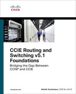
Let’s say we come across the topology shown in Figure 2-1 and the trouble ticket states that R1 cannot ping R2.
Notice that I intentionally do not comment on whether Figure 2-1 contains a physical or a logical topology. If we read the topology in Figure 2-1 literally, it is tempting to quickly conclude that the two routers are connected back-to-back with an Ethernet crossover cable. However, there is a significant chance, both in the CCIE Lab Exam and in real-life scenarios, that their interconnection is more complex than initially thought.
Let’s troubleshoot this problem. As the first step, let’s verify the ticket by pinging R2 from R1:
R1# ping 12.1.1.2
Type escape sequence to abort.
Sending 5, 100-byte ICMP Echos to 12.1.1.2, timeout is 2 seconds:
.....
Success rate is 0 percent (0/5)
Because the ping is not successful, we should check the ARP table to see if R1 is at least able to learn the MAC address of R2:
R1# show arp
Protocol Address Age (min) Hardware Addr Type Interface
Internet 12.1.1.1 - 0000.1111.1111 ARPA FastEthernet0/0
Internet 12.1.1.2 0 Incomplete ARPA
Obviously, ARP has failed. Because this potentially can be caused by a Layer 2 problem, let’s verify the interface configuration by inspecting the F0/0 configuration on R1:
R1# show run interface FastEthernet0/0
interface FastEthernet0/0
ip address 12.1.1.1 255.255.255.0
mac-address 0000.1111.1111
duplex auto
speed auto
end
Nothing suspicious shows up here. Let’s verify whether there is an access control list configured on R1, which could be blocking the communication in some not-so-obvious way—perhaps in a local Policy Base Routing configuration or a class map:
R1# show access-lists
No ACLs on R1, either. Let’s see if R1 is connected directly to R2:
R1# show cdp neighbors
Capability Codes: R - Router, T - Trans Bridge, B - Source Route Bridge
S - Switch, H - Host, I - IGMP, r - Repeater, P - Phone,
D - Remote, C - CVTA, M - Two-port Mac Relay
Device ID Local Intrfce Holdtme Capability Platform Port ID
SW1 Fas 0/0 154 S I WS-C3560- Fas 0/1
As it turns out, R1 is not connected to R2; rather, it connects to SW1’s F0/1 interface. Obviously, there is at least one switch between R1 and R2 that was not depicted in Figure 2-1, and as a consequence, we immediately know that Figure 2-1 is not a physical topology diagram. Let’s therefore check the configuration of the F0/1 interface on SW1:
SW1# show run interface Fastethernet0/1
interface FastEthernet0/1
switchport access vlan 12
switchport mode access
spanning-tree portfast
end
We can see that the F0/1, and R1 along with it, is placed into VLAN 12. Let’s check for access control lists (ACLs) or virtual LAN (VLAN) access maps on SW1 that could be blocking the communication:
SW1# show access-lists
SW1# show vlan access-map
No ACLs, no VLAN access maps. Let’s view the topology from the perspective of the Spanning Tree Protocol (STP):
SW1# show spanning-tree vlan 12
VLAN0012
Spanning tree enabled protocol ieee
Root ID Priority 32780
Address 0012.7f40.9380
This bridge is the root
Hello Time 2 sec Max Age 20 sec Forward Delay 15 sec
Bridge ID Priority 32780 (priority 32768 sys-id-ext 12)
Address 0012.7f40.9380
Hello Time 2 sec Max Age 20 sec Forward Delay 15 sec
Aging Time 300
Interface Role Sts Cost Prio.Nbr Type
---------------- ---- --- --------- -------- -------------------------
Fa0/1 Desg FWD 19 128.3 P2p Edge
Fa0/21 Desg FWD 19 128.23 P2p
We know already that the F0/1 interface of SW1 is connected to R1, and it looks like SW1 is connected to another device via its F0/21 interface. Cisco Discovery Protocol (CDP) can hopefully tell us more about the neighboring device:
SW1# show cdp neighbors
Capability Codes: R - Router, T - Trans Bridge, B - Source Route Bridge
S - Switch, H - Host, I - IGMP, r - Repeater, P - Phone
Device ID Local Intrfce Holdtme Capability Platform Port ID
SW3 Fas 0/21 172 S I WS-C3550- Fas 0/21
R1 Fas 0/1 142 R S I 2811 Fas 0/0
In this output, we can see that F0/21 on SW1 connects to another switch whose name is SW3. Let’s move on to SW3 and verify its ACLs, VLAN access maps, and STP:
SW3# show access-lists
SW3# show vlan access-map
SW3# show spanning-tree vlan 12
Spanning tree instance(s) for vlan 12 does not exist.
SW3 reports that there is no STP instance for VLAN 12. That either means that the VLAN does not exist on this switch or that there are no ports in VLAN 12 that are currently in the up/up state. Let’s verify the VLAN database first:
SW3# show vlan brief
VLAN Name Status Ports
---- -------------------------------- --------- -------------------------------
1 default active Fa0/1, Fa0/2, Fa0/3, Fa0/4
Fa0/5, Fa0/6, Fa0/7, Fa0/8
Fa0/9, Fa0/10, Fa0/11, Fa0/12
Fa0/13, Fa0/14, Fa0/15, Fa0/16
Fa0/17, Fa0/18, Fa0/20, Fa0/22
Fa0/23, Fa0/24, Gi0/1, Gi0/2
1002 fddi-default act/unsup
1003 token-ring-default act/unsup
1004 fddinet-default act/unsup
1005 trnet-default act/unsup
Clearly, VLAN 12 is missing. Let’s create it:
Note When configuring a VLAN in the global configuration mode, you must exit the VLAN submode in order for the changes to apply.
SW3(config)# vlan 12
SW3(config-vlan)# exit
While we are on SW3, let’s verify the topology from the perspective of STP:
SW3# show spanning-tree vlan 12
VLAN0012
Spanning tree enabled protocol ieee
Root ID Priority 32780
Address 000c.858b.7a00
This bridge is the root
Hello Time 2 sec Max Age 20 sec Forward Delay 15 sec
Bridge ID Priority 32780 (priority 32768 sys-id-ext 12)
Address 000c.858b.7a00
Hello Time 2 sec Max Age 20 sec Forward Delay 15 sec
Aging Time 300
Interface Role Sts Cost Prio.Nbr Type
---------------- ---- --- --------- -------- --------------------------
Fa0/21 Desg FWD 19 128.21 P2p
Although there is no obvious problem in this output, it is slightly suspicious that the only port participating in VLAN 12 should be F0/21, which goes back to SW1. In order for R1 and R2 to communicate, R2 must be connected to a port—either on this switch or on some other switch—that participates in VLAN 12, and so far, neither SW1 nor SW3 shows such a port. Next, let’s verify the trunk interfaces configured on SW3:
SW3# show interface trunk
Port Mode Encapsulation Status Native vlan
Fa0/19 on 802.1q trunking 1
Fa0/21 on 802.1q trunking 1
Port Vlans allowed on trunk
Fa0/19 1-11,13-4094
Fa0/21 1-4094
Port Vlans allowed and active in management domain
Fa0/19 1
Fa0/21 1,12
Port Vlans in spanning tree forwarding state and not pruned
Fa0/19 1
Fa0/21 1,12
We can see that VLAN 12 is not allowed on the F0/19 interface, even though F0/19 is a trunk port leading to some yet-unknown device. Why is that?
SW3# show run interface Fasterethernet0/19
interface FastEthernet0/19
switchport trunk encapsulation dot1q
switchport trunk allowed vlan 1-11,13-4094
switchport mode trunk
end
We can clearly see the problem: VLAN 12 is not in the list of allowed VLANs on this trunk. Let’s add it:
SW3(config)# interface FastEthernet0/19
SW3(config-if)# switchport trunk allowed vlan add 12
We can now verify the modification, like so:
SW3# show interface trunk
Port Mode Encapsulation Status Native vlan
Fa0/19 on 802.1q trunking 1
Fa0/21 on 802.1q trunking 1
Port Vlans allowed on trunk
Fa0/19 1-4094
Fa0/21 1-4094
Port Vlans allowed and active in management domain
Fa0/19 1,12
Fa0/21 1,12
Port Vlans in spanning tree forwarding state and not pruned
Fa0/19 1,12
Fa0/21 1,12
This looks much better. What does the STP say now?
SW3# show spanning-tree vlan 12
VLAN0012
Spanning tree enabled protocol ieee
Root ID Priority 32780
Address 000c.858b.7a00
This bridge is the root
Hello Time 2 sec Max Age 20 sec Forward Delay 15 sec
Bridge ID Priority 32780 (priority 32768 sys-id-ext 12)
Address 000c.858b.7a00
Hello Time 2 sec Max Age 20 sec Forward Delay 15 sec
Aging Time 300
Interface Role Sts Cost Prio.Nbr Type
---------------- ---- --- --------- -------- --------------------------------
Fa0/19 Desg FWD 19 128.19 P2p
Fa0/21 Desg FWD 19 128.21 P2p
Using CDP, we should now see the device that is connected to the F0/19 interface of SW3:
SW3# show cdp neighbors
Capability Codes: R - Router, T - Trans Bridge, B - Source Route Bridge
S - Switch, H - Host, I - IGMP, r - Repeater, P - Phone
Device ID Local Intrfce Holdtme Capability Platform Port ID
SW4 Fas 0/19 162 S I WS-C3550- Fas 0/19
SW1 Fas 0/21 123 S I WS-C3560- Fas 0/21
According to this output, F0/19 on SW3 leads to SW4. Let’s move to SW4, then, and verify the VLAN database on SW4 right away:
SW4# show vlan brief
VLAN Name Status Ports
---- -------------------------------- --------- -------------------------------
1 default active Fa0/1, Fa0/2, Fa0/3, Fa0/4
Fa0/5, Fa0/6, Fa0/7, Fa0/8
Fa0/9, Fa0/10, Fa0/11, Fa0/12
Fa0/13, Fa0/14, Fa0/15, Fa0/16
Fa0/17, Fa0/18, Fa0/20, Fa0/22
Fa0/23, Fa0/24, Gi0/1, Gi0/2
1002 fddi-default act/unsup
1003 token-ring-default act/unsup
1004 fddinet-default act/unsup
1005 trnet-default act/unsup
VLAN 12 is not configured on this switch. Let’s add it and verify the topology from the perspective of STP:
SW4(config)# vlan 12
SW4(config-vlan)# exit
SW4(config)# end
SW4# show interface trunk
Port Mode Encapsulation Status Native vlan
Fa0/19 on 802.1q trunking 1
Fa0/21 on 802.1q trunking 1
Port Vlans allowed on trunk
Fa0/19 1-4094
Fa0/21 1-4094
Port Vlans allowed and active in management domain
Fa0/19 1,12
Fa0/21 1,12
Port Vlans in spanning tree forwarding state and not pruned
Fa0/19 1,12
Fa0/21 1,12
SW4# show spanning-tree vlan 12
VLAN0012
Spanning tree enabled protocol ieee
Root ID Priority 32780
Address 000c.302d.9980
This bridge is the root
Hello Time 2 sec Max Age 20 sec Forward Delay 15 sec
Bridge ID Priority 32780 (priority 32768 sys-id-ext 12)
Address 000c.302d.9980
Hello Time 2 sec Max Age 20 sec Forward Delay 15 sec
Aging Time 15
Interface Role Sts Cost Prio.Nbr Type
---------------- ---- --- --------- -------- --------------------------------
Fa0/19 Desg FWD 19 128.19 P2p
Fa0/21 Desg FWD 19 128.21 P2p
SW4 is connected to a device through its F0/21 interface. Let’s verify this information with CDP:
SW4# show cdp neighbors
Capability Codes: R - Router, T - Trans Bridge, B - Source Route Bridge
S - Switch, H - Host, I - IGMP, r - Repeater, P - Phone
Device ID Local Intrfce Holdtme Capability Platform Port ID
SW2 Fas 0/21 149 S I WS-C3560- Fas 0/21
SW3 Fas 0/19 136 S I WS-C3550- Fas 0/19
SW4 is connected to SW2 via its F0/21 interface, so let’s move on to SW2:
SW2# show vlan brief
VLAN Name Status Ports
---- -------------------------------- --------- -------------------------------
1 default active Fa0/1, Fa0/3, Fa0/4, Fa0/5
Fa0/6, Fa0/7, Fa0/8, Fa0/9
Fa0/10, Fa0/11, Fa0/12, Fa0/13
Fa0/14, Fa0/15, Fa0/16, Fa0/17
Fa0/18, Fa0/19, Fa0/20, Fa0/22
Fa0/23, Fa0/24, Gi0/1, Gi0/2
12 VLAN0012 active Fa0/2
1002 fddi-default act/unsup
1003 token-ring-default act/unsup
1004 fddinet-default act/unsup
1005 trnet-default act/unsup
VLAN 12 does exist on SW2, and the only access port in this VLAN is F0/2. Before we verify reachability, let’s see the STP status:
SW2# show spanning-tree vlan 12
VLAN0012
Spanning tree enabled protocol ieee
Root ID Priority 32780
Address 000c.302d.9980
Cost 19
Port 23 (FastEthernet0/21)
Hello Time 2 sec Max Age 20 sec Forward Delay 15 sec
Bridge ID Priority 32780 (priority 32768 sys-id-ext 12)
Address 001d.e5d6.0000
Hello Time 2 sec Max Age 20 sec Forward Delay 15 sec
Aging Time 300
Interface Role Sts Cost Prio.Nbr Type
---------------- ---- --- --------- -------- -------------------------
Fa0/2 Desg FWD 19 128.4 P2p Edge
Fa0/21 Root FWD 19 128.23 P2p
All looks good here. Let’s see which device is connected to the F0/2 interface of SW2:
SW2# show cdp neighbors
Capability Codes: R - Router, T - Trans Bridge, B - Source Route Bridge
S - Switch, H - Host, I - IGMP, r - Repeater, P - Phone
Device ID Local Intrfce Holdtme Capability Platform Port ID
SW4 Fas 0/21 144 S I WS-C3550- Fas 0/21
R2 Fas 0/2 126 R S I 2811 Fas 0/1
The output of the preceding show command reveals that the Fa0/2 interface of SW2 is connected to R2’s Fa0/1 interface. Let’s go to R2 and verify reachability with R1:
R2# ping 12.1.1.1
Type escape sequence to abort.
Sending 5, 100-byte ICMP Echos to 12.1.1.1, timeout is 2 seconds:
.!!!!
Success rate is 80 percent (4/5), round-trip min/avg/max = 1/1/4 ms
The problem is fixed, and we can see how a simple logical diagram can translate into the physical diagram shown in Figure 2-2.
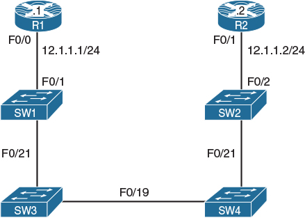
Figure 2-2 Physical Topology of the Network
Lab 2-2: Physical-to-Logical Topology
By this point, it should be obvious how important it is to know the physical topology of a given logical topology. This next lab demonstrates the configuration of physical topology in order to achieve a particular logical topology, and it will give you a better understanding of what to expect in the actual CCIE lab.
Figures 2-3 and 2-4 describe the physical connections of routers and switches. Figure 2-5 shows the desired logical topology that will be created as a result of accomplishing the tasks in this lab.

Figure 2-3 Physical Topology—Router Connections to Switches
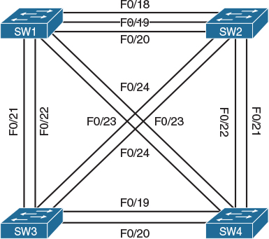
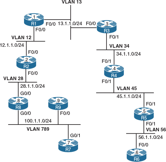
Figure 2-5 Desired Logical Topology
Task 1
Shut down all ports on all switches:
! On all switches:
SWx(config)# interface range fastethernet0/1 – 24
SWx(config-if-range)# shutdown
SWx(config-if-range)# interface range gigabitethernet0/1 – 2
SWx(config-if-range)# shutdown
Task 2
Configure the hostnames of the switches based on the following assignment:
![]() Switch 1: SW1
Switch 1: SW1
![]() Switch 2: SW2
Switch 2: SW2
![]() Switch 3: SW3
Switch 3: SW3
To perform this task, do the following:
! On Switch 1:
Switch(config)# hostname SW1
! On Switch 2:
Switch(config)# hostname SW2
! On Switch 3:
Switch(config)# hostname SW3
Task 3
Configure the physical topology to implement the logical topology shown in Figure 2-3. If this configuration is completed successfully, every router should be able to ping its neighboring routers in the same subnet.
Let’s do a top-down configuration starting from VLAN 13. As shown in Figure 2-5, the F0/0 interfaces of R1 and R3 should be placed into VLAN 13. However, the R1 F0/0 interface also appears in VLAN 12 toward R2. In other words, R1 F0/0 participates in two distinct VLANs, and this requires creating two subinterfaces under this interface, one for each VLAN. Additionally, according to Figure 2-3, R1 F0/0 connects to the SW1 F0/1 interface, which can also be confirmed by using the command show cdp neighbors after both interfaces are started. Consequently, the SW1 F0/1 interface must carry multiple VLANs, so it must be configured as a trunk.
Note Although the subinterface number (the X in F0/0.X) does not need to match the VLAN ID of the subinterface, looking at the full name makes it much easier to know the VLAN of the subinterface.
! On SW1:
SW1(config)# interface fastethernet0/1
SW1(config-if)# switchport trunk encapsulation dot1q
SW1(config-if)# switchport mode trunk
SW1(config-if)# no shutdown
! On R1:
Router(config)# hostname R1
R1(config)# interface fastethernet0/0
R1(config-if)# no shutdown
R1(config-if)# exit
R1(config)# interface fastethernet0/0.12
R1(config-subif)# encapsulation dot1q 12
R1(config-subif)# ip address 12.1.1.1 255.255.255.0
R1(config-subif)# exit
R1(config)# interface fastethernet0/0.13
R1(config-subif)# encapsulation dot1q 13
R1(config-subif)# ip address 13.1.1.1 255.255.255.0
R1(config-subif)# do show cdp neighbors
Capability Codes: R - Router, T - Trans Bridge, B - Source Route Bridge
S - Switch, H - Host, I - IGMP, r - Repeater, P - Phone,
D - Remote, C - CVTA, M - Two-port Mac Relay
Device ID Local Intrfce Holdtme Capability Platform Port ID
SW1 Fas 0/0 143 S I WS-C3560- Fas 0/1
Note that we have not created VLAN 13 on the switch yet.
Next, we focus on R3 F0/0. Figure 2-5 shows that this interface participates only in VLAN 13, and according to Figure 2-3, R3 F0/0 connects to SW1 F0/3. Although we could solve this task by using subinterfaces on R3 and trunking on SW1, it would make the configuration needlessly complex. In this particular topology, R3 F0/0 is never going to participate in multiple VLANs, so it is perfectly fine to directly configure F0/0 on R3 without subinterfaces and to make F0/3 on SW1 a simple access port in VLAN 13. Note that SW1 creates an access VLAN automatically if that VLAN does not exist at the moment of adding an access port to it.
! On SW1:
SW1(config)# interface fastethernet0/3
SW1(config-if)# switchport mode access
SW1(config-if)# switchport access vlan 13
% Access VLAN does not exist. Creating vlan 13
SW1(config-if)# no shutdown
! On R3:
R3(config)# interface fastethernet0/0
R3(config-if)# ip address 13.1.1.3 255.255.255.0
R3(config-if)# no shutdown
Now verify the configuration:
! On SW1 – VLAN 13 should exist
SW1# show vlan brief
VLAN Name Status Ports
---- -------------------------------- --------- -------------------------------
1 default active Fa0/2, Fa0/4, Fa0/5, Fa0/6
Fa0/7, Fa0/8, Fa0/9, Fa0/10
Fa0/11, Fa0/12, Fa0/13, Fa0/14
Fa0/15, Fa0/16, Fa0/17, Fa0/18
Fa0/19, Fa0/20, Fa0/23, Fa0/24
Gi0/1, Gi0/2
13 VLAN0013 active Fa0/3
1002 fddi-default act/unsup
1003 token-ring-default act/unsup
1004 fddinet-default act/unsup
1005 trnet-default act/unsup
! On R1: Pinging between R1 and R3 should work
R1# ping 13.1.1.3
Type escape sequence to abort.
Sending 5, 100-byte ICMP Echos to 13.1.1.3, timeout is 2 seconds:
.!!!!
Success rate is 80 percent (4/5), round-trip min/avg/max = 1/1/1 ms
Let’s move on to VLAN 12. In VLAN 12, we have the R1 F0/0 and R2 F0/0 interfaces. The R1 F0/0 interface is already configured with a subinterface for this VLAN (VLAN 12). Figure 2-5 shows that the R2 F0/0 interface is again placed into two VLANs: 12 and 28. Therefore, we will configure R2 F0/0 with two subinterfaces—one for VLAN 12 and the second one for VLAN 28. Also, according to Figure 2-3, R2 F0/0 connects to SW1 F0/2. This switchport is again required to carry multiple VLANs, so it must be configured as a trunk.
! On SW1:
SW1(config)# interface fastethernet0/2
SW1(config-if)# switchport trunk encapsulation dot1q
SW1(config-if)# switchport mode trunk
SW1(config-if)# no shutdown
! On R2:
R2(config)# interface fastethernet0/0
R2(config-if)# no shutdown
R2(config-if)# exit
R2(config-if)# interface fastethernet0/0.12
R2(config-subif)# encapsulation dot1q 12
R2(config-subif)# ip address 12.1.1.2 255.255.255.0
R2(config-subif)# exit
R2(config)# interface fastethernet0/0.28
R2(config-subif)# encapsulation dot1q 28
R2(config-subif)# ip address 28.1.1.2 255.255.255.0
Now verify the VLANs on SW1, like so:
SW1# show vlan brief
VLAN Name Status Ports
---- -------------------------------- --------- -------------------------------
1 default active Fa0/2, Fa0/4, Fa0/5, Fa0/6
Fa0/7, Fa0/8, Fa0/9, Fa0/10
Fa0/11, Fa0/12, Fa0/13, Fa0/14
Fa0/15, Fa0/16, Fa0/17, Fa0/18
Fa0/19, Fa0/20, Fa0/23, Fa0/24
Gi0/1, Gi0/2
13 VLAN0013 active Fa0/3
1002 fddi-default act/unsup
1003 token-ring-default act/unsup
1004 fddinet-default act/unsup
1005 trnet-default act/unsup
As you can see, VLAN 12 is not created yet because it wasn’t configured explicitly and an access port wasn’t configured in VLAN 12. Therefore, we need to add VLAN 12 to SW1 explicitly:
Note Creating or modifying VLANs in global configuration mode is one of the very few commands in Cisco IOS that is not applied immediately after you enter it. With VLANs, all changes are applied only after you exit the VLAN configuration submode.
SW1(config)# vlan 12
SW1(config-vlan)# exit
Now, test the reachability between R1 and R2:
R1# ping 12.1.1.2
Type escape sequence to abort.
Sending 5, 100-byte ICMP Echos to 12.1.1.2, timeout is 2 seconds:
.!!!!
Success rate is 80 percent (4/5), round-trip min/avg/max = 1/2/4 ms
Let’s move on to VLAN 28.
R2 has been already configured with a proper subinterface for VLAN 28. To complete the configuration on R8, first note that in Figure 2-5, G0/0 on R8 is shown to participate in two VLANs: 28 and 789. Therefore, R8 will need to be configured with two subinterfaces—one for each of these VLANs. The configuration steps on R8 and SW1 are as follows:
1. Configure the SW1 F0/8 interface toward R8 G0/0 as a trunk port.
2. Create VLAN 28 on SW1.
3. Configure the R8 G0/0 interface with two subinterfaces—one for VLAN 28 and the other one for VLAN 789.
4. Configure the R8 subinterface in VLAN 28 with an IP address of 28.1.1.8/24.
5. Configure the R8 subinterface in VLAN 789 with an IP address of 100.1.1.8/24.
! On SW1:
SW1(config)# interface fastethernet0/8
SW1(config-if)# switchport trunk encapsulation dot1q
SW1(config-if)# switchport mode trunk
SW1(config-if)# no shutdown
SW1(config-if)# exit
SW1(config)# vlan 28
SW1(config-vlan)# exit
! On R8:
R8(config)# interface gigabitethernet0/0
R8(config-if)# no shutdown
R8(config-if)# exit
R8(config)# interface gigabitethernet0/0.28
R8(config-subif)# encapsulation dot1q 28
R8(config-subif)# ip address 28.1.1.8 255.255.255.0
R8(config-subif)# exit
R8(config)# interface gigabitethernet0/0.789
R8(config-subif)# encapsulation dot1q 789
R8(config-subif)# ip address 100.1.1.8 255.255.255.0
Now verify and test the configuration:
! On SW1:
SW1# show vlan brief
VLAN Name Status Ports
---- -------------------------------- --------- -------------------------------
1 default active Fa0/4, Fa0/5, Fa0/6, Fa0/7
Fa0/9, Fa0/10, Fa0/11, Fa0/12
Fa0/13, Fa0/14, Fa0/15, Fa0/16
Fa0/17, Fa0/18, Fa0/19, Fa0/20
Fa0/23, Fa0/24, Gi0/1, Gi0/2
12 VLAN0012 active
13 VLAN0013 active Fa0/3
28 VLAN0028 active
1002 fddi-default act/unsup
1003 token-ring-default act/unsup
1004 fddinet-default act/unsup
1005 trnet-default act/unsup
! On R2:
R2# ping 28.1.1.8
Type escape sequence to abort.
Sending 5, 100-byte ICMP Echos to 28.1.1.8, timeout is 2 seconds:
.!!!!
Success rate is 80 percent (4/5), round-trip min/avg/max = 1/1/4 ms
Having this done, let’s proceed to VLAN 789.
VLAN 789 consists of the R8 G0/0, R9 F0/0, and R7 G0/1 interfaces. Looking at the physical topology diagram in Figure 2-3, you can see that the R8 G0/0 and R9 F0/0 interfaces are connected to SW1 but the R7 G0/1 interface is connected to SW2. In other words, VLAN 789 members are spread across two switches. To have VLAN 789 span two switches, we need to configure a trunk between SW1 and SW2 to pass the VLAN 789 traffic between them. Any of the direct links between SW1 and SW2 shown in Figure 2-4 can be used for this purpose.
Furthermore, Figure 2-5 shows that the R7 G0/1 and R9 F0/0 interfaces participate only in VLAN 789; therefore, we do not need to configure them with subinterfaces. R8 has already been configured for VLAN 789 connectivity, so we don’t need to focus on it at this point.
The steps to configure this part of the topology are as follows:
1. Configure the SW1 F0/9 interface toward R9 F0/0 as an access port in VLAN 789.
2. Configure a trunk between SW1 and SW2. We’ll choose F0/19 for this purpose.
3. Configure the SW2 F0/7 interface toward R7 G0/1 as an access port in VLAN 789.
4. Configure the R7 G0/1 interface with an IP address of 100.1.1.7/24.
5. Configure the R9 F0/0 interface with an IP address of 100.1.1.9/24.
! On SW1:
SW1(config)# interface fastethernet0/9
SW1(config-if)# switchport mode access
SW1(config-if)# switchport access vlan 789
% Access VLAN does not exist. Creating vlan 789
SW1(config-if)# no shutdown
SW1(config-if)# exit
SW1(config)# interface fastethernet0/19
SW1(config-if)# switchport trunk encapsulation dot1q
SW1(config-if)# switchport mode trunk
SW1(config-if)# no shutdown
! On SW2:
SW2(config)# interface fastethernet0/19
SW2(config-if)# switchport trunk encapsulation dot1q
SW2(config-if)# switchport mode trunk
SW2(config-if)# no shutdown
SW2(config-if)# exit
SW2(config)# interface fastethernet0/7
SW2(config-if)# switchport mode access
SW2(config-if)# switchport access vlan 789
% Access VLAN does not exist. Creating vlan 789
SW2(config-if)# no shutdown
! On R7:
R7(config)# interface gigabitethernet0/1
R7(config-if)# ip address 100.1.1.7 255.255.255.0
R7(config-if)# no shutdown
! On R9:
R9(config)# interface fastethernet0/0
R9(config-if)# ip address 100.1.1.9 255.255.255.0
R9(config-if)# no shutdown
Now let’s test the connectivity:
R8# ping 100.1.1.7
Type escape sequence to abort.
Sending 5, 100-byte ICMP Echos to 100.1.1.7, timeout is 2 seconds:
.!!!!
Success rate is 80 percent (4/5), round-trip min/avg/max = 1/1/1 ms
R8# ping 100.1.1.9
Type escape sequence to abort.
Sending 5, 100-byte ICMP Echos to 100.1.1.9, timeout is 2 seconds:
.!!!!
Success rate is 80 percent (4/5), round-trip min/avg/max = 1/1/4 ms
Now we can move to VLAN 34 and work down all the way to VLAN 56.
VLAN 34 interconnects the F0/1 interfaces of R3 and R4, but in Figure 2-5, the R4 F0/1 interface appears in two different VLANs. This translates into the following sequence of steps:
1. Configure the SW2 F0/3 interface toward R3 F0/1 as an access port in VLAN 34.
2. Configure the SW2 F0/4 interface toward R4 F0/1 as a trunk port.
3. Configure the R3 F0/1 interface with an IP address of 34.1.1.3/24.
4. Configure the R4 F0/1 interface with two subinterfaces—one in VLAN 34 and the second in VLAN 45.
5. Configure the R4 subinterface in VLAN 34 with an IP address of 34.1.1.4/24.
6. Configure the R4 subinterface in VLAN 45 with an IP address of 45.1.1.4/24.
! On SW2:
SW2(config)# interface fastethernet0/3
SW2(config-if)# switchport mode access
SW2(config-if)# switchport access vlan 34
% Access VLAN does not exist. Creating vlan 34
SW2(config-if)# no shutdown
SW2(config-if)# exit
SW2(config)# interface fastethernet0/4
SW2(config-if)# switchport trunk encapsulation dot1q
SW2(config-if)# switchport mode trunk
SW2(config-if)# no shutdown
! On R3:
R3(config)# interface fastethernet0/1
R3(config-if)# ip address 34.1.1.3 255.255.255.0
R3(config-if)# no shutdown
! On R4:
R4(config)# interface fastethernet0/1
R4(config-if)# no shutdown
R4(config-if)# exit
R4(config)# interface fastethernet0/1.34
R4(config-subif)# encapsulation dot1q 34
R4(config-subif)# ip address 34.1.1.4 255.255.255.0
R4(config-subif)# exit
R4(config)# interface fastethernet0/1.45
R4(config-subif)# encapsulation dot1q 45
R4(config-subif)# ip address 45.1.1.4 255.255.255.0
Let’s now test the configuration:
! On SW2:
SW2# show vlan brief
VLAN Name Status Ports
---- -------------------------------- --------- -------------------------------
1 default active Fa0/1, Fa0/2, Fa0/5, Fa0/6
Fa0/8, Fa0/9, Fa0/10, Fa0/11
Fa0/12, Fa0/13, Fa0/14, Fa0/15
Fa0/16, Fa0/17, Fa0/18, Fa0/20
Fa0/21, Fa0/22, Gi0/1, Gi0/2
34 VLAN0034 active Fa0/3
789 VLAN0789 active Fa0/7
1002 fddi-default act/unsup
1003 token-ring-default act/unsup
1004 fddinet-default act/unsup
1005 trnet-default act/unsup
! On R3:
R3# ping 34.1.1.4
Type escape sequence to abort.
Sending 5, 100-byte ICMP Echos to 34.1.1.4, timeout is 2 seconds:
.!!!!
Success rate is 80 percent (4/5), round-trip min/avg/max = 1/1/1 ms
Let’s move on to VLAN 45. This VLAN should connect together the F0/1 interfaces of R4 and R5, but once again the R5 F0/1 interface is also in another VLAN (VLAN 56). Note that R4 has already been configured with the necessary settings for VLAN 45.
Hence, the steps for configuring the VLAN 45 segment are as follows:
![]() Configure the SW2 F0/5 interface toward R5 F0/1 as a trunk port.
Configure the SW2 F0/5 interface toward R5 F0/1 as a trunk port.
![]() Create VLAN 45 on SW2.
Create VLAN 45 on SW2.
![]() Configure the R5 F0/1 interface with two subinterfaces—one in VLAN 56 and the second in VLAN 45.
Configure the R5 F0/1 interface with two subinterfaces—one in VLAN 56 and the second in VLAN 45.
![]() Configure the R5 subinterface in VLAN 45 with an IP address of 45.1.1.5/24.
Configure the R5 subinterface in VLAN 45 with an IP address of 45.1.1.5/24.
![]() Configure the R5 subinterface in VLAN 56 with an IP address of 56.1.1.5/24.
Configure the R5 subinterface in VLAN 56 with an IP address of 56.1.1.5/24.
! On SW2:
SW2(config)# interface fastethernet0/5
SW2(config-if)# switchport trunk encapsulation dot1q
SW2(config-if)# switchport mode trunk
SW2(config-if)# no shutdown
SW2(config-if)# exit
SW2(config)# vlan 45
SW2(config-vlan)# exit
! On R5:
R5(config)# interface fastethernet0/1
R5(config-if)# no shutdown
R5(config-if)# exit
R5(config)# interface fastethernet0/1.45
R5(config-subif)# encapsulation dot1q 45
R5(config-subif)# ip address 45.1.1.5 255.255.255.0
R5(config-subif)# exit
R5(config)# interface fastethernet0/1.56
R5(config-subif)# encapsulation dot1q 56
R5(config-subif)# ip address 56.1.1.5 255.255.255.0
Now let’s verify the connectivity between R4 and R5:
R5# ping 45.1.1.4
Type escape sequence to abort.
Sending 5, 100-byte ICMP Echos to 45.1.1.4, timeout is 2 seconds:
.!!!!
Success rate is 80 percent (4/5), round-trip min/avg/max = 1/2/4 ms
The last segment of this topology is VLAN 56. Following Figure 2-5, routers R5 and R6 are connected together in this VLAN using the R5 F0/1 and R6 F0/0 interfaces. On R5, we have already created the proper subinterface under its F0/1 interface. R6 does not use its F0/0 for any other connection, so R6 does not need to use subinterfaces. However, because R5 F0/1 is connected to SW2 F0/5 whereas R6 F0/0 is connected to SW1 F0/6, VLAN 56 needs to span both switches, which means we need a working trunk between SW1 and SW2.
We first verify whether there is a trunk configured between the two switches:
SW2# show interface trunk
Port Mode Encapsulation Status Native vlan
Fa0/4 on 802.1q trunking 1
Fa0/5 on 802.1q trunking 1
Fa0/19 on 802.1q trunking 1
Port Vlans allowed on trunk
Fa0/4 1-4094
Fa0/5 1-4094
Fa0/19 1-4094
Port Vlans allowed and active in management domain
Fa0/4 1,34,45,789
Fa0/5 1,34,45,789
Fa0/19 1,34,45,789
Port Vlans in spanning tree forwarding state and not pruned
Fa0/4 1,34,45,789
Fa0/5 1,34,45,789
Fa0/19 1,34,45,789
F0/19 is the trunk link between the switches we set up earlier, and it is shown correctly in the output.
Next, verify whether VLAN 56 is created on both SW1 and SW2, and if it isn’t, create it:
! On SW1:
SW1(config)# do show vlan brief
VLAN Name Status Ports
---- -------------------------------- --------- -------------------------------
1 default active Fa0/4, Fa0/5, Fa0/6, Fa0/7
Fa0/10, Fa0/11, Fa0/12, Fa0/13
Fa0/14, Fa0/15, Fa0/16, Fa0/17
Fa0/18, Fa0/20, Fa0/21, Fa0/22
Fa0/23, Fa0/24, Gi0/1, Gi0/2
12 VLAN0012 active
13 VLAN0013 active Fa0/3
28 VLAN0028 active
789 VLAN0789 active Fa0/9
1002 fddi-default act/unsup
1003 token-ring-default act/unsup
1004 fddinet-default act/unsup
1005 trnet-default act/unsup
! VLAN 56 is missing; create it manually.
SW1(config)# vlan 56
SW1(config-vlan)# exit
! On SW2:
SW2(config)# do show vlan brief | e unsup
VLAN Name Status Ports
---- -------------------------------- --------- -------------------------------
1 default active Fa0/1, Fa0/2, Fa0/6, Fa0/8
Fa0/9, Fa0/10, Fa0/11, Fa0/12
Fa0/13, Fa0/14, Fa0/15, Fa0/16
Fa0/17, Fa0/18, Fa0/20, Fa0/21
Fa0/22, Fa0/23, Fa0/24, Gi0/1
Gi0/2
34 VLAN0034 active Fa0/3
45 VLAN0045 active
789 VLAN0789 active Fa0/7
! VLAN 56 is missing; create it manually.
SW2(config)# vlan 56
SW2(config-vlan)# exit
At this point, you might wonder why VLAN 56 was not propagated automatically by the VLAN Trunking Protocol (VTP) from SW1 to SW2. In order for VLANs to be propagated to another switch over VTP, the following must be true:
![]() A trunk link must be connecting the two switches. (This is already configured.)
A trunk link must be connecting the two switches. (This is already configured.)
![]() The switches must operate in VTP Server or Client mode. By default, switches run in the VTP Server mode.
The switches must operate in VTP Server or Client mode. By default, switches run in the VTP Server mode.
![]() If VTPv3 is in use, the primary server must be elected. By default, switches run VTPv1.
If VTPv3 is in use, the primary server must be elected. By default, switches run VTPv1.
![]() The VTP domain name must match and be non-NULL. Because we have not touched VTP settings, both switches default to the NULL (empty) VTP domain name, and so the VLAN database contents are not propagated.
The VTP domain name must match and be non-NULL. Because we have not touched VTP settings, both switches default to the NULL (empty) VTP domain name, and so the VLAN database contents are not propagated.
Let’s finish the necessary configurations:
! On SW1:
SW1(config)# interface fastethernet0/6
SW1(config-if)# switchport mode access
SW1(config-if)# switchport access vlan 56
SW1(config-if)# no shut
! On R6:
R6(config)# interface fastethernet0/0
R6(config-if)# ip address 56.1.1.6 255.255.255.0
R6(config-if)# no shutdown
Now let’s verify and test the configuration:
! On SW1:
SW1# show vlan brief | exclude unsup
VLAN Name Status Ports
---- -------------------------------- --------- -------------------------------
1 default active Fa0/4, Fa0/5, Fa0/7, Fa0/10
Fa0/11, Fa0/12, Fa0/13, Fa0/14
Fa0/15, Fa0/16, Fa0/17, Fa0/18
Fa0/20, Fa0/21, Fa0/22, Fa0/23
Fa0/24, Gi0/1, Gi0/2
12 VLAN0012 active
13 VLAN0013 active Fa0/3
28 VLAN0028 active
56 VLAN0056 active Fa0/6
789 VLAN0789 active Fa0/9
SW1# show interface fastethernet0/19 trunk
Port Mode Encapsulation Status Native vlan
Fa0/19 on 802.1q trunking 1
Port Vlans allowed on trunk
Fa0/19 1-4094
Port Vlans allowed and active in management domain
Fa0/19 1,12-13,28,56,789
Port Vlans in spanning tree forwarding state and not pruned
Fa0/19 1,12-13,28,56,789
! On R6:
R6# ping 56.1.1.5
Type escape sequence to abort.
Sending 5, 100-byte ICMP Echos to 56.1.1.5, timeout is 2 seconds:
.!!!!
Success rate is 80 percent (4/5), round-trip min/avg/max = 1/2/4 ms
With this test, Task 3 has been fully completed. Erase the startup configurations and reload the routers and switches before proceeding to the next lab.
Summary
In this chapter, we have explored the steps required to translate from a logical topology to a physical topology. This skillset is essential in order to extrapolate any information not provided by a drawing given to you in the exam. I will go a step further by stating that this is one of the most critical skills needed to function as a consultant who is exposed to many new and different network environments. It is widely considered the most useful troubleshooting skill there is.