Chapter 14 Multicast
Lab 14-1: IGMP
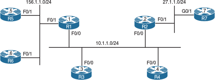
Figure 14-1 Configuring Internet Group Management Protocol (IGMP)
Figure 14-1 illustrates the topology that will be used in the following lab.
Task 1
Enable multicast routing on R1 and R2 and configure their F0/0 and F0/1 interfaces in PIM dense mode.
There are two types of multicast routing protocols: dense mode and sparse mode. Dense mode uses a push model, meaning that the multicast traffic is flooded throughout the network. This is called a flood and prune model because initially the traffic is flooded to the network, but after the initial flood the routers with no receivers are pruned.
On both R1 and R2, IP multicast routing is disabled by default and needs to be enabled using the ip multicast-routing command on all devices.
The following commands enable PIM dense mode for the requested interfaces; in order to enable any multicasting on a given interface, you must have IP multicast-routing. If it is not configured, you will receive a console warning message:
WARNING: "ip multicast-routing" is not configured,
IP Multicast packets will not be forwarded
Let’s enable Protocol Independent Multicast (PIM) dense mode:
On R1:
R1(config)# interface FastEthernet0/0
R1(config-if)# ip pim dense-mode
R1(config)# interface FastEthernet0/1
R1(config-if)# ip pim dense-mode
On R2:
R2(config)# interface FastEthernet0/0
R2(config-if)# ip pim dense-mode
R2(config)# interface FastEthernet0/1
R2(config-if)# ip pim dense-mode
Now let’s verify the configuration:
On R1:
R1# show ip pim interface
Address Interface Ver/ Nbr Query DR DR
Mode Count Intvl Prior
10.1.1.1 FastEthernet0/0 v2/D 1 30 1 10.1.1.2
156.1.1.1 FastEthernet0/1 v2/D 0 30 1 156.1.1.1
On R2:
R2# show ip pim interface
Address Interface Ver/ Nbr Query DR DR
Mode Count Intvl Prior
10.1.1.2 FastEthernet0/0 v2/D 1 30 1 10.1.1.2
27.1.1.2 FastEthernet0/1 v2/D 0 30 1 27.1.1.2
By looking at the DR column in the preceding output, you can see that 10.1.1.2 (R2) is the Designated Router (DR) for 10.1.1.0/24 segment, and 27.1.1.2 (R2) is also the DR for its F0/1 segment.
On R1:
R1# show ip mroute
IP Multicast Routing Table
Flags: D - Dense, S - Sparse, B - Bidir Group, s - SSM Group, C - Connected,
L - Local, P - Pruned, R - RP-bit set, F - Register flag,
T - SPT-bit set, J - Join SPT, M - MSDP created entry, E - Extranet,
X - Proxy Join Timer Running, A - Candidate for MSDP Advertisement,
U - URD, I - Received Source Specific Host Report,
Z - Multicast Tunnel, z - MDT-data group sender,
Y - Joined MDT-data group, y - Sending to MDT-data group,
V - RD & Vector, v - Vector
Outgoing interface flags: H - Hardware switched, A - Assert winner
Timers: Uptime/Expires
Interface state: Interface, Next-Hop or VCD, State/Mode
(*, 224.0.1.40), 06:35:29/00:02:35, RP 0.0.0.0, flags: DCL
Incoming interface: Null, RPF nbr 0.0.0.0
Outgoing interface list:
FastEthernet0/0, Forward/Dense, 06:35:28/stopped
When PIM is enabled on a given interface, IGMP is also enabled.
Note The (*, 224.0.1.40) entry is always created when PIM is enabled on a Cisco router. Each router will start generating V2 general queries on their multicast-enabled interfaces for group 224.0.1.40. This multicast group is used by Auto-RP, which is discussed later in this chapter.
Let’s verify the configuration:
On R1:
R1# show ip igmp interface FastEthernet0/0
FastEthernet0/0 is up, line protocol is up
Internet address is 10.1.1.1/24
IGMP is enabled on interface <---------------------------------- Line 1
Current IGMP host version is 2 <-------------------------------- Line 2
Current IGMP router version is 2
IGMP query interval is 60 seconds <----------------------------- Line 3
IGMP configured query interval is 60 seconds
IGMP querier timeout is 120 seconds <--------------------------- Line 4
IGMP configured querier timeout is 120 seconds
IGMP max query response time is 10 seconds <-------------------- Line 5
Last member query count is 2
Last member query response interval is 1000 ms
Inbound IGMP access group is not set
IGMP activity: 1 joins, 0 leaves
Multicast routing is enabled on interface
Multicast TTL threshold is 0
Multicast designated router (DR) is 10.1.1.2 <------------------ Line 6
IGMP querying router is 10.1.1.1 (this system)<----------------- Line 7
Multicast groups joined by this system (number of users):
224.0.1.40(1)
Here are some points to keep in mind:
![]() Lines 1 and 2: By default, when PIM is configured on an interface, IGMPv2 is also enabled; the version of IGMP can be changed using the ip igmp version command.
Lines 1 and 2: By default, when PIM is configured on an interface, IGMPv2 is also enabled; the version of IGMP can be changed using the ip igmp version command.
![]() Lines 3 and 4: The IGMP query interval states the frequency at which the IGMP querier sends IGMP-Host-Query messages through this interface. These messages are sent by the querier in order to discover which multicast groups have members on the interface. The default value is 60 seconds; this value can be changed using the ip igmp query-interval interface configuration command.
Lines 3 and 4: The IGMP query interval states the frequency at which the IGMP querier sends IGMP-Host-Query messages through this interface. These messages are sent by the querier in order to discover which multicast groups have members on the interface. The default value is 60 seconds; this value can be changed using the ip igmp query-interval interface configuration command.
By default, if the querier misses two queries in a row, the other router(s) on the segment will trigger an election to elect a new querier. Therefore, when the IP IGMP query interval is changed, IOS will automatically change the IGMP querier timeout value to twice the query interval. However, the querier timeout can be changed using the ip igmp querier-timeout interface command.
![]() Line 5: By default, the IGMP max query response time is set to 10 seconds; in IGMP version 2 (IGMPv2), this counter is advertised in IGMP queries to the hosts, informing them of the maximum time within which they must respond to a general query. This improves the “burstiness” of the responses. This default value can be changed using the interface configuration ip igmp query-max-response-time command.
Line 5: By default, the IGMP max query response time is set to 10 seconds; in IGMP version 2 (IGMPv2), this counter is advertised in IGMP queries to the hosts, informing them of the maximum time within which they must respond to a general query. This improves the “burstiness” of the responses. This default value can be changed using the interface configuration ip igmp query-max-response-time command.
![]() Lines 6 and 7: Note that the querier is responsible for forwarding the multicast flows. IGMPv1 did not have a querier election; therefore, it was the decision of the multicast routing protocol to elect a DR for this purpose.
Lines 6 and 7: Note that the querier is responsible for forwarding the multicast flows. IGMPv1 did not have a querier election; therefore, it was the decision of the multicast routing protocol to elect a DR for this purpose.
A formal querying router election process was specified within the IGMPv2 protocol. In IGMPv2, each router on a multi-access network will initially assume that it is the querier and begins by sending queries; each router connected to that multi-access network will see the queries from the other IGMPv2 routers and will examine the source IP address of the query messages. All IGMPv2 routers will then elect the router with the lowest source IP address as the IGMP querier. If the elected router fails to send query messages within a specified time limit, the routers on that multi-access network will initiate the query election once again. IGMPv2 is described in RFC 2236.
The concept of a Designated Router (DR) will be covered in later labs.
Task 2
Disable IP routing on R3 and R4 and configure their F0/0 interface to join 224.1.1.1 multicast group:
On R3 and R4:
Rx(config)# no ip routing
Two commands that are somewhat identical are ip igmp static-group and ip igmp join-group.
The ip igmp static-group command configures a static group membership entry on an interface, which allows the router to join the multicast group. This configuration of the ip igmp static-group command will cause the upstream router(s) to maintain the multicast routing table information for that group, which ensures that all the paths to that multicast group are active. Remember that this command does not process the ping packets; it just joins the group and floods the multicast flow.
The ip igmp join-group command allows the router to process and respond to ping commands. This can be a useful administrative and debugging tool. This command can configure the router to emulate a client connected to a last-hop router, whereas the ping command performed on a router can configure the router to act as a server.
We will have both R3 and R4 join the same multicast group. This is accomplished as follows:
On R3 and R4:
Rx(config)# interface FastEthernet0/0
Rx(config-if)# ip igmp join-group 224.1.1.1
Let’s verify the configuration:
On R1:
R1# show ip igmp groups
IGMP Connected Group Membership
Group Address Interface Uptime Expires Last Reporter Group Accounted
224.1.1.1 FastEthernet0/0 00:00:36 00:02:46 10.1.1.4
224.0.1.40 FastEthernet0/0 00:30:04 00:01:57 10.1.1.2
Note R4 (10.1.1.4) is the last host to report being a member of the 224.1.1.1 multicast group (in your configuration this could be 10.1.1.3). The Uptime column specifies how long the multicast group has been known. The Expires column specifies how long until the entry expires. The entry starts with 2 minutes and 59 seconds, and it counts down all the way to 2 minutes and then back up to 2:59, because every 60 seconds the querier sends IGMP-Host-Query messages. If there is an active group member, it will reply within 10 seconds; therefore, this counter should not go below 2 minutes unless there are no active group members.
Task 3
Disable IP routing on R5 and R6 and configure their F0/1 interfaces to join the 224.56.56.56 multicast group:
On R5 and R6:
Rx(config)# no ip routing
Rx(config)# interface FastEthernet0/1
Rx(config-if)# ip igmp Join-group 224.56.56.56
Let’s verify the configuration:
On R1:
R1# show ip igmp groups
IGMP Connected Group Membership
Group Address Interface Uptime Expires Last Reporter Group Accounted
224.56.56.56 FastEthernet0/1 00:02:38 00:02:05 156.1.1.5
224.1.1.1 FastEthernet0/0 00:21:41 00:02:06 10.1.1.4
224.0.1.40 FastEthernet0/0 01:25:26 00:02:11 10.1.1.1
On R5:
R5# show ip igmp interface FastEthernet0/1 | begin Multicast groups
Multicast groups joined by this system (number of users):
224.56.56.56(1)
R5# show ip igmp groups
IGMP Connected Group Membership
Group Address Interface Uptime Expires Last Reporter Group Accounted
224.56.56.56 FastEthernet0/1 00:06:10 never 156.1.1.5
Note Because the router’s interface is configured with an igmp join-group command, the Expires column shows never.
Task 4
Disable IP routing on R7 and configure its G0/1 interface to join the 224.7.7.7 multicast group:
On R7:
R7(config)# no ip routing
R7(config)# interface GigabitEthernet0/1
R7(config-if)# ip igmp join-group 224.7.7.7
Let’s verify the configuration:
On R7:
R7# show ip igmp interface GigabitEthernet0/1 | begin Multicast groups
Multicast groups joined by this system (number of users):
224.7.7.7(1)
On R2:
R2# show ip igmp groups | exclude 224.0.1.40
IGMP Connected Group Membership
Group Address Interface Uptime Expires Last Reporter Group Accounted
224.7.7.7 FastEthernet0/1 00:00:09 00:02:50 27.1.1.7
224.1.1.1 FastEthernet0/0 00:18:22 00:02:34 10.1.1.3
Task 5
Configure R1 to restrict hosts connected to its F0/1 interface from joining the 224.5.5.5 and 224.6.6.6 multicast groups.
Note The following standard access list denies the two groups and allows the others:
On R1:
R1# show access-lists
R1(config)# ip access-list standard TST
R1(config-std-nacl)# deny 224.5.5.5
R1(config-std-nacl)# deny 224.6.6.6
R1(config-std-nacl)# permit any
The Access-list is applied to the F0/1 interface of R1
R1(config)# interface FastEthernet0/1
R1(config-if)# ip igmp access-group TST
The following debug is enabled for verification purpose:
R1# debug ip igmp
IGMP debugging is on
Let’s verify and test the configuration:
On R5:
R5(config)# interface FastEthernet0/1
R5(config-if)# ip igmp join-group 224.5.5.5
On R6:
R6(config)# interface FastEthernet0/1
R6(config-if)# ip igmp join-group 224.6.6.6
On R1:
Note: You should see the following messages in the output of the debug:
Received v2 Report on FastEthernet0/1 from 10.1.156.5 for 224.5.5.5
Group 224.5.5.5 access denied on FastEthernet0/1
Received v2 Report on FastEthernet0/1 from 10.1.156.6 for 224.6.6.6
Group 224.6.6.6 access denied on FastEthernet0/1
Let’s disable the debug:
R1# undebug all
All possible debugging has been turned off
R1# show ip igmp groups | exclude 224.0.1.40
IGMP Connected Group Membership
Group Address Interface Uptime Expires Last Reporter Group Accounted
224.56.56.56 FastEthernet0/1 00:27:54 00:02:57 156.1.1.6
224.1.1.1 FastEthernet0/0 00:46:56 00:02:51 10.1.1.4
R1# show ip igmp interface FastEthernet0/1
FastEthernet0/1 is up, line protocol is up
Internet address is 156.1.1.1/24
IGMP is enabled on interface
Current IGMP host version is 2
Current IGMP router version is 2
IGMP query interval is 60 seconds
IGMP configured query interval is 60 seconds
IGMP querier timeout is 120 seconds
IGMP configured querier timeout is 120 seconds
IGMP max query response time is 10 seconds
Last member query count is 2
Last member query response interval is 1000 ms
Inbound IGMP access group is TST
IGMP activity: 2 joins, 1 leaves
Multicast routing is enabled on interface
Multicast TTL threshold is 0
Multicast designated router (DR) is 156.1.1.1 (this system)
IGMP querying router is 156.1.1.1 (this system)
No multicast groups joined by this system
Task 6
Because there is only a single host connected to the F0/1 interface of R2, R2 should be configured such that it stops forwarding multicast traffic for all groups immediately upon receipt of an IGMPv2 group leave message:
On R2:
R2(config)# interface FastEthernet0/1
R2(config-if)# ip igmp immediate-leave group-list 1
R2# show access-list
R2(config)# access-list 1 permit 224.0.0.0 15.255.255.255
Note If ip igmp immediate-leave group-list 1 is configured in the global configuration mode, it is applied to all interfaces. In this case, it is applied to the F0/1 interface; therefore, it affects hosts that are connected to the F0/1 interface of R2. Note that the access list matches all Class D addresses, thus affecting all multicast groups.
To see how this command works, let’s enable debug ip igmp on R2 and remove the ip igmp join-group 224.2.2.2 command and view the results:
R2# debug ip igmp
IGMP debugging is on
On R7:
R7(config)# interface GigabitEthernet0/1
R7(config-if)# no ip igmp join-group 224.7.7.7
On R2:
IGMP(0): Received Leave from 27.1.1.7 (FastEthernet0/1) for 224.7.7.7
IGMP(0): Leave group 224.2.2.2 immediately on FastEthernet0/1
IGMP(0): Deleting 224.7.7.7 on FastEthernet0/1
IGMP(0): MRT delete FastEthernet0/1 for (*,224.7.7.7) by 3
Based on this output, you can see that once R7 was configured to remove the ip igmp join-group command, it sent a leave message for group 224.7.7.7, and R7 immediately removed the group.
In the next test, we will add the ip igmp join-group 224.7.7.7 command on R7 and remove the ip igmp immediate-leave group-list 1 command from R2. Then we will remove the ip igmp join-group 224.7.7.7 command from R7 and view the result:
On R7:
R7(config)# interface GigabitEthernet0/1
R7(config-if)# ip igmp join-group 224.7.7.7
On R2:
R2(config)# interface FastEthernet0/1
R2(config-if)# no ip igmp immediate-leave group-list 1
On R7:
R7(config)# interface GigabitEthernet0/1
R7(config-if)# no ip igmp join-group 224.7.7.7
Now, let’s examine the output of the debug on R2:
On R2:
IGMP(0): Received Leave from 27.1.1.7 (FastEthernet0/1) for 224.7.7.7
IGMP(0): Received Group record for group 224.7.7.7, mode 3 from 27.1.1.7 for 0 sources
IGMP(0): Lower expiration timer to 2000 msec for 224.7.7.7 on FastEthernet0/1
IGMP(0): Send v2 Query on FastEthernet0/1 for group 224.7.7.7
IGMP(0): Send v2 Query on FastEthernet0/1 for group 224.7.7.7
IGMP(0): Switching to INCLUDE mode for 224.7.7.7 on FastEthernet0/1
IGMP(0): MRT delete FastEthernet0/1 for (*,224.7.7.7) by 0
You can see that the local router (R2) sent a query once it received the leave message from R7. Let’s disable debug ip igmp, add ip igmp immediate-leave group-list 1 on R2, and add igmp join-group on R7:
On R2:
R2# undebug all
All possible debugging has been turned off
R2(config)# interface FastEthernet0/1
R2(config-if)# ip igmp immediate-leave group-list 1
On R7:
R7(config)# interface GigabitEthernet0/1
R7(config-if)# ip igmp join-group 224.7.7.7
Task 7
Configure R1 such that before it stops forwarding the multicast traffic out of its F0/0 interface, it sends three IGMP query messages at 500-ms intervals after receiving an IGMP group-specific leave message.
Let’s begin by viewing the default value:
On R1:
R1# show ip igmp interface FastEthernet0/0
FastEthernet0/0 is up, line protocol is up
Internet address is 10.1.1.1/24
IGMP is enabled on interface
Current IGMP host version is 2
Current IGMP router version is 2
IGMP query interval is 60 seconds
IGMP configured query interval is 60 seconds
IGMP querier timeout is 120 seconds
IGMP configured querier timeout is 120 seconds
IGMP max query response time is 10 seconds
Last member query count is 2
Last member query response interval is 1000 ms
Inbound IGMP access group is not set
IGMP activity: 3 joins, 1 leaves
Multicast routing is enabled on interface
Multicast TTL threshold is 0
Multicast designated router (DR) is 10.1.1.2
IGMP querying router is 10.1.1.1 (this system)
Multicast groups joined by this system (number of users):
224.0.1.40(1)
Note The default last member query count (LMQC) is set to 2, and the interval is set to 1 second (1000 ms). The following command sets the LMQC to 3:
On R1:
R1(config)# interface FastEthernet0/0
R1(config-if)# ip igmp last-member-query-count 3
Let’s verify the configuration:
On R1:
R1# show ip igmp interface FastEthernet0/0 | include Last
Last member query count is 3
Last member query response interval is 1000 ms
Now let’s set the interval for these messages:
On R1:
R1(config)# interface FastEthernet0/0
R1(config-if)# ip igmp last-member-query-interval 500
Now we’ll verify the configuration:
On R1:
R1# show ip igmp interface FastEthernet0/0 | include Last
Last member query count is 3
Last member query response interval is 500 ms
Task 8
Configure R2 such that the number of mroute states created as a result of host membership reports is 3. This policy should only affect R2’s F0/1 interface.
The following solution can be applied in global configuration mode or interface configuration mode. When it’s configured in global config mode, it’s applied to the entire router and it’s referred to as “Global IGMP State Limiter,” which means that it affects the router globally. However, if it is configured in the interface config mode, the effect is for the hosts connected to that given interface only.
On R2:
R2(config)# interface FastEthernet0/1
R2(config-if)# ip igmp limit 3
Let’s verify the configuration:
On R2:
R2# show ip igmp interface FastEthernet0/1 | include Limit
Interface IGMP State Limit : 1 active out of 3 max
Note The output of the preceding show command states that there is one active group out of a maximum of three groups, whereas the output of the following show command reveals that there is a single group on R2’s F0/1 interface:
R2# show ip igmp groups FastEthernet0/1
IGMP Connected Group Membership
Group Address Interface Uptime Expires Last Reporter Group Accounted
224.7.7.7 FastEthernet0/1 00:11:59 00:02:26 27.1.1.7 Ac
Now let’s test the configuration. In testing the solution, R7 is configured to join additional groups and the mroute state is verified on R2; once the limit is reached, R2 denies creating additional mroute states:
On R7:
R7(config)# interface GigabitEthernet0/1
R7(config-if)# ip igmp join-group 224.22.22.22
On R2:
R2# show ip igmp group FastEthernet0/1
IGMP Connected Group Membership
Group Address Interface Uptime Expires Last Reporter Group Accounted
224.22.22.22 FastEthernet0/1 00:00:24 00:02:35 27.1.1.7 Ac
224.7.7.7 FastEthernet0/1 00:17:14 00:02:35 27.1.1.7 Ac
Note An mroute state is created for group 224.22.22.22, as shown here:
R2# show ip igmp interface FastEthernet0/1 | include Limit
Interface IGMP State Limit : 2 active out of 3 max
R2# show ip mroute | include 224.22.22.22
(*, 224.22.22.22), 00:02:15/00:02:02, RP 0.0.0.0, flags: DC
On R7:
!Note: The following is the third group:
R7(config)# interface GigabitEthernet0/1
R7(config-if)# ip igmp join-group 224.222.222.222
On R2:
R2# show ip igmp group FastEthernet0/1
IGMP Connected Group Membership
Group Address Interface Uptime Expires Last Reporter Group Accounted
224.22.22.22 FastEthernet0/1 00:02:08 00:02:52 27.1.1.7 Ac
224.7.7.7 FastEthernet0/1 00:18:57 00:02:52 27.1.1.7 Ac
224.222.222.222 FastEthernet0/1 00:00:07 00:02:52 27.1.1.7 Ac
R2# show ip mroute | include 224.222.222.222
(*, 224.222.222.222), 00:00:58/00:02:01, RP 0.0.0.0, flags: DC
R2# show ip igmp interface FastEthernet0/1 | include Limit
Interface IGMP State Limit : 3 active out of 3 max
Note R2 has created an mroute state and has reached its maximum allowable mroute states. To see the effect of the ip igmp limit command, configure the debug ip igmp command on R2, as follows:
On R2:
R2# debug ip igmp
IGMP debugging is on
Let’s configure R7 with the fourth group:
On R7:
R7(config)# interface GigabitEthernet0/1
R7(config-if)# ip igmp join-group 224.220.220.220
On R2, you should see the following debug output:
On R2:
IGMP(0): Received v2 Report on FastEthernet0/1 from 27.1.1.7 for 224.220.220.220
IGMP(0): Received Group record for group 224.220.220.220, mode 2 from 27.1.1.7 for 0 sources
IGMP_ACL(0): Group 224.220.220.220 access denied on FastEthernet0/1
R2# show ip igmp groups FastEthernet0/1
IGMP Connected Group Membership
Group Address Interface Uptime Expires Last Reporter Group Accounted
224.22.22.22 FastEthernet0/1 00:02:08 00:02:52 27.1.1.7 Ac
224.7.7.7 FastEthernet0/1 00:18:57 00:02:52 27.1.1.7 Ac
224.222.222.222 FastEthernet0/1 00:00:07 00:02:52 27.1.1.7 Ac
Note As shown here, there are three groups, which is the maximum allowed number:
R2# show ip igmp interface FastEthernet0/1 | include Limit
Interface IGMP State Limit : 3 active out of 3 max
Let’s disable the debug ip igmp command on R2:
On R2
R2# undebug all
Task 9
Configure R1 and R2 such that if the existing querier is down for longer than 90 seconds, a new querier is elected for the 10.1.1.0/24 network.
The output of the following show command displays the existing querying router and the query interval:
On R1:
R1# show ip igmp interface FastEthernet0/0 | include IGMP quer
IGMP query interval is 60 seconds
IGMP querier timeout is 120 seconds
IGMP querying router is 10.1.1.1 (this system)
On R2:
R2# show ip igmp interface FastEthernet0/0 | include IGMP quer
IGMP query interval is 60 seconds
IGMP querier timeout is 120 seconds
IGMP querying router is 10.1.1.1
You can see that both R1 and R2 agree that R1 (10.1.1.1) is the querying router and that the timers match.
Let’s configure the task.
Note By default, if the querier is down, the other routers on the same subnet will wait twice the query interval specified by ip igmp query-interval before the election is reinitiated.
The following command changes the wait time to 90 seconds:
On R1 and R2:
Rx(config)# interface FastEthernet0/0
Rx(config-if)# ip igmp querier-timeout 90
Let’s verify the configuration:
On R1:
R1# show ip igmp interface FastEthernet0/0 | include IGMP quer
IGMP query interval is 60 seconds
IGMP querier timeout is 90 seconds
IGMP querying router is 10.1.1.1 (this system)
On R2:
R2# show ip igmp interface FastEthernet0/0 | include IGMP quer
IGMP query interval is 60 seconds
IGMP querier timeout is 90 seconds
IGMP querying router is 10.1.1.1
Now we need to verify and test the configuration.
The existing querier is R1 (10.1.1.1). Let’s shut down the F0/0 interface of R1 and see the change take effect in 90 seconds:
On R1:
R1(config)# interface FastEthernet0/0
R1(config-if)# shutdown
You should see the following console message:
%PIM-5-NBRCHG: neighbor 10.1.1.2 DOWN on interface FastEthernet0/0 DR
The following show command is entered within 90 seconds, and as you can see, R2 is the new querying router:
R2# show ip igmp interface DastWthernet0/0 | include IGMP quer
IGMP query interval is 60 seconds
IGMP querier timeout is 90 seconds
IGMP querying router is 10.1.1.2 (this system)
Let’s reconfigure R1 as the querier:
On R1:
R1(config)# interface FastEthernet0/0
R1(config-if)# no shutdown
Now let’s verify the configuration:
On R2:
R2# show ip igmp interface FastEthernet0/0 | include IGMP quer
IGMP query interval is 60 seconds
IGMP querier timeout is 90 seconds
IGMP querying router is 10.1.1.1
The second the F0/0 interface of R1 is up, it becomes the querier immediately.
Task 10
The F0/0 interfaces of R1 and R2 should be configured to advertise the period during which the responder can respond to an IGMP query message before these routers delete the group to its maximum allowable value.
This is controlled through the ip igmp query-max-response-time interface configuration command:
On R1 and R2:
RX# show ip igmp interface FastEthernet0/0 | include IGMP max
IGMP max query response time is 10 seconds
The default is 10 seconds. The following command changes this value, whose range is 1–25 seconds:
On R1 and R2:
Rx(config)# interface FastEthernet0/0
Rx(config-if)# ip igmp query-max-response-time ?
<1-25> query response value in seconds
Rx(config-if)# ip igmp query-max-response-time 25
Let’s verify the configuration:
RX# show ip igmp interface FastEthernet0/0 | include IGMP max
IGMP max query response time is 25 seconds
Erase the startup configuration and reload the routers before proceeding to the next lab.
Lab 14-2: Static RP
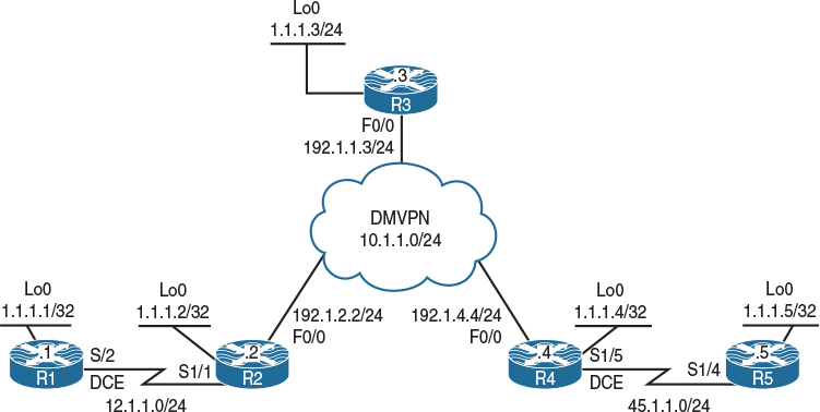
Figure 14-2 Configuring Static RP
Task 1
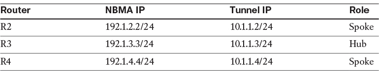
Configure the topology shown in Figure 14-2 based on the policy detailed in Table 14-1.
Table 14-1 Policy Configuration for Task 1
You should use specific static routes to provide reachability for the dynamic multipoint virtual private network (DMVPN) NBMA IP addresses. The DMVPN should be configured in Phase 1:
On SW1:
SW1(config)# interface range FastEthernet0/2 - 4
SW1(config-if-range)# no switchport
SW1(config)# interface FastEthernet0/2
SW1(config-if)# ip address 192.1.2.10 255.255.255.0
SW1(config-if)# no shutdown
SW1(config)# interface FastEthernet0/3
SW1(config-if)# ip address 192.1.3.10 255.255.255.0
SW1(config-if)# no shutdown
SW1(config)# interface FfastEthernet0/4
SW1(config-if)# ip address 192.1.4.10 255.255.255.0
SW1(config-if)# no shutdown
SW1(config)# ip routing
On R1:
R1(config)# interface loopback0
R1(config-if)# ip address 1.1.1.1 255.255.255.255
R1(config)# interface serial1/2
R1(config-if)# clock rate 64000
R1(config-if)# ip address 12.1.1.1 255.255.255.0
R1(config-if)# no shutdown
On R2:
R2(config)# interface loopback0
R2(config-if)# ip address 1.1.1.2 255.255.255.255
R2(config)# interface serial1/1
R2(config-if)# ip address 12.1.1.2 255.255.255.0
R2(config-if)# no shutdown
R2(config)# interface FastEthernet0/0
R2(config-if)# ip address 192.1.2.2 255.255.255.0
R2(config-if)# no shutdown
R2(config)# ip route 192.1.4.4 255.255.255.255 192.1.2.10
R2(config)# ip route 192.1.3.3 255.255.255.255 192.1.2.10
R2(config)# interface tunnel1
R2(config-if)# ip address 10.1.1.2 255.255.255.0
R2(config-if)# tunnel source FastEthernet0/0
R2(config-if)# tunnel destination 192.1.3.3
R2(config-if)# ip nhrp network 222
R2(config-if)# ip nhrp nhs 10.1.1.3
R2(config-if)# ip nhrp map 10.1.1.3 192.1.3.3
R2(config-if)# ip nhrp map multicast 192.1.3.3
On R3:
R3(config)# interface loopback0
R3(config-if)# ip address 1.1.1.3 255.255.255.255
R3(config)# interface FastEthernet0/0
R3(config-if)# ip address 192.1.3.3 255.255.255.0
R3(config-if)# no shutdown
R3(config)# ip route 192.1.2.2 255.255.255.255 192.1.3.10
R3(config)# ip route 192.1.4.4 255.255.255.255 192.1.3.10
R3(config)# interface tunnel1
R3(config-if)# ip address 10.1.1.3 255.255.255.0
R3(config-if)# tunnel source FastEthernet/0
R3(config-if)# tunnel mode gre multipoint
R3(config-if)# ip nhrp network 333
R3(config-if)# ip nhrp map multicast dynamic
On R4:
R4(config)# interface loopback0
R4(config-if)# ip address 1.1.1.4 255.255.255.255
R4(config)# interface FastEthernet0/0
R4(config-if)# ip address 192.1.4.4 255.255.255.0
R4(config-if)# no shutdown
R4(config)# interface serial1/5
R4(config-if)# clock rate 64000
R4(config-if)# ip address 45.1.1.4 255.255.255.0
R4(config-if)# no shutdown
R4(config)# ip route 192.1.3.3 255.255.255.255 192.1.4.10
R4(config)# ip route 192.1.2.2 255.255.255.255 192.1.4.10
R4(config)# interface tunnel1
R4(config-if)# ip address 10.1.1.4 255.255.255.0
R4(config-if)# tunnel source FastEthernet0/0
R4(config-if)# tunnel destination 192.1.3.3
R4(config-if)# ip nhrp network 444
R4(config-if)# ip nhrp nhs 10.1.1.3
R4(config-if)# ip nhrp map 10.1.1.3 192.1.3.3
R4(config-if)# ip nhrp map multi 192.1.3.3
On R5:
R5(config)# interface loopback0
R5(config-if)# ip address 1.1.1.5 255.255.255.255
R5(config)# interface serial1/4
R5(config-if)# ip address 45.1.1.5 255.255.255.0
R5(config-if)# no shutdown
Let’s verify the configuration:
On R2:
R2# ping 12.1.1.1
Type escape sequence to abort.
Sending 5, 100-byte ICMP Echos to 12.1.1.1, timeout is 2 seconds:
!!!!!
Success rate is 100 percent (5/5), round-trip min/avg/max = 28/29/32 ms
R2# ping 10.1.1.3
Type escape sequence to abort.
Sending 5, 100-byte ICMP Echos to 10.1.1.3, timeout is 2 seconds:
!!!!!
Success rate is 100 percent (5/5), round-trip min/avg/max = 1/2/4 ms
R2# ping 10.1.1.4
Type escape sequence to abort.
Sending 5, 100-byte ICMP Echos to 10.1.1.4, timeout is 2 seconds:
!!!!!
Success rate is 100 percent (5/5), round-trip min/avg/max = 4/5/8 ms
On R5:
R5# ping 45.1.1.4
Type escape sequence to abort.
Sending 5, 100-byte ICMP Echos to 45.1.1.4, timeout is 2 seconds:
!!!!!
Success rate is 100 percent (5/5), round-trip min/avg/max = 28/28/32 ms
Task 2
Configure OSPF Area 0 on all routers in the topology shown in Figure 14-2 and ensure reachability to all links and loopback interfaces in this diagram. The DMVPN tunnel is configured in Phase 2 and should not be changed to another phase.
On R1:
R1(config)# router ospf 1
R1(config-router)# network 12.1.1.1 0.0.0.0 area 0
R1(config-router)# network 1.1.1.1 0.0.0.0 area 0
On R2:
R2(config)# router ospf 1
R2(config-router)# network 1.1.1.2 0.0.0.0 area 0
R2(config-router)# network 12.1.1.2 0.0.0.0 area 0
R2(config-router)# network 10.1.1.2 0.0.0.0 area 0
R2(config-router)# interface tunnel1
R2(config-if)# ip ospf hello-interval 10
You should see the following console message:
%OSPF-5-ADJCHG: Process 1, Nbr 1.1.1.1 on Serial1/1 from LOADING to FULL, Loading Done
On R3:
R3(config)# interface tunnel1
R3(config-if)# ip ospf network point-to-multipoint
R3(config-if)# ip ospf hello-interval 10
R3(config)# router ospf 1
R3(config-router)# network 1.1.1.3 0.0.0.0 area 0
R3(config-router)# network 10.1.1.3 0.0.0.0 area 0
You should also see this console message:
%OSPF-5-ADJCHG: Process 1, Nbr 1.1.1.2 on Tunnel1 from LOADING to FULL, Loading Done
On R4:
R4(config)# router ospf 1
R4(config-router)# network 1.1.1.4 0.0.0.0 area 0
R4(config-router)# network 10.1.1.4 0.0.0.0 area 0
R4(config-router)# network 45.1.1.4 0.0.0.0 area 0
R4(config-router)# interface tunnel1
R4(config-if)# ip ospf hello-interval 10
You should see this console message as well:
%OSPF-5-ADJCHG: Process 1, Nbr 1.1.1.3 on Tunnel1 from LOADING to FULL, Loading Done
On R5:
R5(config)# router ospf 1
R5(config-router)# network 1.1.1.5 0.0.0.0 area 0
R5(config-router)# network 45.1.1.5 0.0.0.0 area 0
Finally, you should see this console message:
%OSPF-5-ADJCHG: Process 1, Nbr 1.1.1.4 on Serial1/4 from LOADING to FULL,
Loading Done
Let’s verify the configuration:
On R1:
R1# show ip route ospf | begin Gate
Gateway of last resort is not set
1.0.0.0/32 is subnetted, 5 subnets
O 1.1.1.2 [110/782] via 12.1.1.2, 00:04:33, Serial1/2
O 1.1.1.3 [110/1782] via 12.1.1.2, 00:02:33, Serial1/2
O 1.1.1.4 [110/2782] via 12.1.1.2, 00:01:33, Serial1/2
O 1.1.1.5 [110/3563] via 12.1.1.2, 00:00:33, Serial1/2
10.0.0.0/8 is variably subnetted, 2 subnets, 2 masks
O 10.1.1.0/24 [110/1781] via 12.1.1.2, 00:04:33, Serial1/2
O 10.1.1.3/32 [110/1781] via 12.1.1.2, 00:02:43, Serial1/2
45.0.0.0/24 is subnetted, 1 subnets
O 45.1.1.0 [110/3562] via 12.1.1.2, 00:01:23, Serial1/2
R1# ping 1.1.1.5
Type escape sequence to abort.
Sending 5, 100-byte ICMP Echos to 1.1.1.5, timeout is 2 seconds:
!!!!!
Success rate is 100 percent (5/5), round-trip min/avg/max = 56/57/60 ms
Task 3
Configure PIM sparse mode on all the interfaces in the topology. Do not configure PIM on the F0/0 interfaces of R2, R3, and R4.
The first step is to enable multicast routing. Once multicast routing is enabled, you can enable PIM sparse mode on the interfaces:
On R1:
R1(config)# ip multicast-routing
R1(config)# interface loopback0
R1(config-if)# ip pim sparse-mode
R1(config)# interface serial1/2
R1(config-if)# ip pim sparse-mode
On R2:
R2(config)# ip multicast-routing
R2(config)# interface loopback0
R2(config-if)# ip pim sparse-mode
R2(config)# interface serial1/1
R2(config-if)# ip pim sparse-mode
R2(config)# interface tunnel1
R2(config-if)# ip pim sparse-mode
You should see the following console message:
%PIM-5-NBRCHG: neighbor 12.1.1.1 UP on interface Serial1/1
On R3:
R3(config)# ip multicast-routing
R3(config)# interface loopback0
R3(config-if)# ip pim sparse-mode
R3(config)# interface tunnel1
R3(config-if)# ip pim sparse-mode
You should also see this console message:
%PIM-5-NBRCHG: neighbor 10.1.1.2 UP on interface Tunnel1
On R4:
R4(config)# ip multicast-routing
R4(config)# interface loopback0
R4(config-if)# ip pim sparse-mode
R4(config)# interface tunnel1
R4(config-if)# ip pim sparse-mode
R4(config)# interface serial1/5
R4(config-if)# ip pim sparse-mode
You should see the following console message as well:
%PIM-5-NBRCHG: neighbor 10.1.1.3 UP on interface Tunnel1
On R5:
R5(config)# ip multicast-routing
R5(config)# interface loopback0
R5(config-if)# ip pim sparse-mode
R5(config)# interface serial1/4
R5(config-if)# ip pim sparse-mode
Finally, you should see this console message:
%PIM-5-NBRCHG: neighbor 45.1.1.4 UP on interface Serial1/4
To verify the configuration, let’s use the following show ip pim neighbor commands, which enable us to verify that the directly connected routers are PIM neighbors:
On R1:
R1# show ip pim neighbor | begin Interface
Neighbor Interface Uptime/Expires Ver DR
Address Prio/Mode
12.1.1.2 Serial1/2 00:07:45/00:01:22 v2 1 / S P G
On R2:
R2# show ip pim neighbor | begin Interface
Neighbor Interface Uptime/Expires Ver DR
Address Prio/Mode
12.1.1.1 Serial1/1 00:05:45/00:01:23 v2 1 / S P G
10.1.1.3 Tunnel1 00:05:17/00:01:40 v2 1 / S P G
On R3:
R3# show ip pim neighbor | begin Interface
Neighbor Interface Uptime/Expires Ver DR
Address Prio/Mode
10.1.1.4 Tunnel1 00:03:45/00:01:27 v2 1 / DR S P G
10.1.1.2 Tunnel1 00:04:45/00:01:24 v2 1 / S P G
On R4:
R4# show ip pim neighbor | begin Interface
Neighbor Interface Uptime/Expires Ver DR
Address Prio/Mode
10.1.1.3 Tunnel1 00:03:34/00:01:38 v2 1 / S P G
45.1.1.5 Serial1/5 00:03:33/00:01:38 v2 1 / S P G
On R5:
R5# show ip pim neighbor | begin Interface
Neighbor Interface Uptime/Expires Ver DR
Address Prio/Mode
45.1.1.4 Serial1/4 00:01:36/00:01:35 v2 1 / S P G
Task 4
R2 should be configured as the Rendezvous Point (RP) for the private group addresses, whereas R3 should be configured as the RP for the remaining groups. You should use static configuration and loopback0 interfaces to accomplish this task.
Even though static RP configuration is the most popular and simplest solution, it is extremely easy to make configuration typos because the same exact configuration needs to be replicated accurately on all routers including the RP.
Here are the configuration tasks:
![]() R2’s Lo0 interface is to be configured as the RP for the private group addresses.
R2’s Lo0 interface is to be configured as the RP for the private group addresses.
![]() R3’s Lo0 interface is to be configured as the RP for all other groups.
R3’s Lo0 interface is to be configured as the RP for all other groups.
For RP’s requirement, you need to configure an access list to identify the private multicast group address range as well as configure the static RP command to reference the access list. This configuration must be done on all routers, including the RP.
Note When an access list is not referenced, the IP address specified in the configuration is configured to be the RP for all groups (224.0.0.0 15.255.255.255):
On All Routers:
Rx# show access-lists
Rx(config)# access-list 2 permit 239.0.0.0 0.255.255.255
Rx(config)# ip pim rp-address 1.1.1.2 2
Rx(config)# ip pim rp-address 1.1.1.3
You should see new tunnel interfaces coming up. On R1 and R5, you should see Tunnel 0 and 1. On R2 and R3, you should see Tunnels 0, 2, and 3. On R4, you should see Tunnels 0 and 2.
Let’s see the reason for these tunnel interfaces:
On R1:
%LINEPROTO-5-UPDOWN: Line protocol on Interface Tunnel0, changed state to up
%LINEPROTO-5-UPDOWN: Line protocol on Interface Tunnel1, changed state to up
R1# show interface tunnel0
Tunnel0 is up, line protocol is up
Hardware is Tunnel
Interface is unnumbered. Using address of Serial1/2 (12.1.1.1)
MTU 17912 bytes, BW 100 Kbit/sec, DLY 50000 usec,
reliability 255/255, txload 1/255, rxload 1/255
Encapsulation TUNNEL, loopback not set
Keepalive not set
Tunnel source 12.1.1.1 (Serial1/2), destination 1.1.1.2
Tunnel Subblocks:
src-track:
Tunnel0 source tracking subblock associated with Serial1/2
Set of tunnels with source Serial1/2, 2 members (includes iterators), on interface <OK>
Tunnel protocol/transport PIM/IPv4
Tunnel TOS/Traffic Class 0xC0, Tunnel TTL 255
Tunnel transport MTU 1472 bytes
Tunnel is transmit only
(The rest of the output is omitted for brevity)
R1# show interface tunnel1
Tunnel1 is up, line protocol is up
Hardware is Tunnel
Interface is unnumbered. Using address of Serial1/2 (12.1.1.1)
MTU 17912 bytes, BW 100 Kbit/sec, DLY 50000 usec,
reliability 255/255, txload 1/255, rxload 1/255
Encapsulation TUNNEL, loopback not set
Keepalive not set
Tunnel source 12.1.1.1 (Serial1/2), destination 1.1.1.3
Tunnel Subblocks:
src-track:
Tunnel1 source tracking subblock associated with Serial1/2
Set of tunnels with source Serial1/2, 2 members (includes iterators), on interface <OK>
Tunnel protocol/transport PIM/IPv4
Tunnel TOS/Traffic Class 0xC0, Tunnel TTL 255
Tunnel transport MTU 1472 bytes
Tunnel is transmit only
(The rest of the output is omitted for brevity)
When multicasting is enabled and the RPs are defined, the non-RP routers assume that they are going to be directly connected to the source. In 12.4 and earlier IOS versions, when the source is initiated, the first-hop router receives the multicast data and encapsulates the multicast data in register messages that are unicasted to the RP.
In IOS releases 15 and later, the register messages are sent through the tunnel that is auto-configured. You can see that these two tunnels are in transmit mode only. The reason you see two tunnels is because you have defined two RPs (1.1.1.2 and 1.1.1.3); therefore, the first tunnel has a destination of 1.1.1.2 and the second tunnel interface has a destination of 1.1.1.3. You can see a similar behavior when multicasting is configured in IPv6. Let’s verify that the tunnel interfaces are used for register messages:
R1(config)# interface tunnel0
%Tunnel0 used by PIM for Registering, configuration not allowed
R1(config)# interface tunnel1
%Tunnel1 used by PIM for Registering, configuration not allowed
The PIM tunnels can also be displayed with the following command:
R1# show ip pim tunnel
Tunnel0
Type : PIM Encap
RP : 1.1.1.2
Source: 12.1.1.1
Tunnel1
Type : PIM Encap
RP : 1.1.1.3
Source: 12.1.1.1
You should see the following console messages on R2 and R3:
%LINEPROTO-5-UPDOWN: Line protocol on Interface Tunnel0, changed state to up
%LINEPROTO-5-UPDOWN: Line protocol on Interface Tunnel2, changed state to up
%LINEPROTO-5-UPDOWN: Line protocol on Interface Tunnel3, changed state to up
Let’s check the tunnels on R2 and R3, which are identical. Tunnel 0 is auto-configured in case the local router is a first-hop router and it needs to send register messages to the RP. As you can see, the destination of the tunnel is 1.1.1.2:
On R2 or R3:
Rx# show interface tunnel0 | include destination|only
Tunnel source 1.1.1.2 (Loopback0), destination 1.1.1.2
Tunnel is transmit only
Tunnel 1 cannot be used because you have configured DMVPN using Tunnel 1; therefore, Tunnel 2 is auto-configured in receive-only mode, as shown next. This tunnel is used for receiving the register messages.
Rx# show interface tunnel2 | include destination|only
Tunnel source 1.1.1.2 (Loopback0), destination 1.1.1.2
Tunnel is receive only
Tunnel 3 is auto-configured for sending stop register messages, and that’s why it’s in transmit-only mode, as shown here:
Rx# show interface tunnel3 | include destination|only
Tunnel source 10.1.1.2 (Tunnel1), destination 1.1.1.3
Tunnel is transmit only
The PIM tunnels can also be displayed with the following command:
R2# show ip pim tunnel
Tunnel0
Type : PIM Encap
RP : 1.1.1.2*
Source: 1.1.1.2
Tunnel3
Type : PIM Encap
RP : 1.1.1.3
Source: 10.1.1.2
Tunnel2
Type : PIM Decap
RP : 1.1.1.2*
Source: -
The asterisk (*) indicates that this router is the RP.
You should see the following console messages on R4:
%LINEPROTO-5-UPDOWN: Line protocol on Interface Tunnel0, changed state to up
%LINEPROTO-5-UPDOWN: Line protocol on Interface Tunnel2, changed state to up
Let’s check Tunnels 0 and 2 on R4:
On R4:
R4# show interface tunnel0 | include destination|only
Tunnel source 10.1.1.4 (Tunnel1), destination 1.1.1.2
Tunnel is transmit only
R4# show interface tunnel2 | include destination|only
Tunnel source 10.1.1.4 (Tunnel1), destination 1.1.1.3
Tunnel is transmit only
The PIM tunnels can also be displayed with the following command:
R4# show ip pim tunnel
Tunnel0
Type : PIM Encap
RP : 1.1.1.2
Source: 10.1.1.4
Tunnel2
Type : PIM Encap
RP : 1.1.1.3
Source: 10.1.1.4
Let’s verify the configuration:
On R1:
R1# show ip pim rp mapping
PIM Group-to-RP Mappings
Note since an access-list was NOT referenced, the router
Acl: 2, Static becomes the RP for ALL Mcast groups
RP: 1.1.1.2 (?)
Group(s): 224.0.0.0/4, Static
RP: 1.1.1.3 (?)
Note The output of the preceding show command reveals that the lo0 interface of R2 is the RP for the groups that are referenced in ACL 2, whereas the lo0 interface of R3 is the RP for the group range of 224.0.0.0/4, meaning all groups.
Because in the preceding configuration the private group addresses are overlapping, the RP with the highest IP address will become the RP for all groups. In this case, R3 is the RP for all groups.
Based on the existing configuration, R3 is chosen as the RP for all groups, and R2 will not be used at all. The correct solution is to configure another access list, deny group 239.0.0.0/8 and allow all other groups, and then reference the access list for R3. This has to be configured on all routers.
On All Routers:
R1# show access-lists
Standard IP access list 2
10 permit 239.0.0.0, wildcard bits 0.255.255.255
Rx(config)# access-list 3 deny 239.0.0.0 0.255.255.255
Rx(config)# access-list 3 permit any
Rx(config)# ip pim rp-address 1.1.1.3 3
Let’s verify the configuration:
On R1:
R1# show ip pim rp mapping
PIM Group-to-RP Mappings
Acl: 2, Static
RP: 1.1.1.2 (?)
Acl: 3, Static
RP: 1.1.1.3 (?)
Note R2 is the RP for the groups defined in ACL #2, and R3 is the RP for groups defined in ACL #3. Remember that the configuration should be performed on all routers, including the RPs.
Task 5
Configure R5’s S1/4 interface to join group 224.5.5.5.
All routers must be able to ping this group:
On R5:
R5(config)# interface s1/4
R5(config-if)# ip igmp join-group 224.5.5.5
Let’s verify the configuration:
On R5:
R5# show ip mroute | section 224.5.5.5
(*, 225.5.5.5), 00:00:08/00:02:51, RP 1.1.1.3, flags: SJPL
Incoming interface: Serial1/4, RPF nbr 45.1.1.4
Outgoing interface list: Null
On R4:
R4# show ip mroute | section 224.5.5.5
(*, 224.5.5.5), 00:01:10/00:03:18, RP 1.1.1.3, flags: S
Incoming interface: Tunnel1, RPF nbr 10.1.1.3
Outgoing interface list:
Serial1/5, Forward/Sparse, 00:01:10/00:03:18
On R3:
R3# show ip mroute | section 224.5.5.5
(*, 224.5.5.5), 00:04:17/00:03:08, RP 1.1.1.3, flags: S
Incoming interface: Null, RPF nbr 0.0.0.0
Outgoing interface list:
Tunnel1, Forward/Sparse, 00:04:17/00:03:08
On R1 and R2:
Rx# show ip mroute | section 224.5.5.5
Note Every PIM-enabled router will create the parent entry (*, 224.5.5.5) in their mroute table. This is created as the join messages are sent from R5 to the RP; R2 and R1 will not have any entry for this group. The RP for this group is 1.1.1.3 (R3). Remember that R3 is the RP for all scopes (local and global scopes) except for the private/admin scope.
Let’s verify the configuration:
On R1:
R1# ping 224.5.5.5
Type escape sequence to abort.
Sending 1, 100-byte ICMP Echos to 224.5.5.5, timeout is 2 seconds:
Reply to request 0 from 45.1.1.5, 76 ms
Reply to request 0 from 45.1.1.5, 88 ms
The reason you see two replies back is because the ping is originated from every multicast-enabled interface.
Let’s verify the configuration:
On R1:
R1# show ip mroute | section 225.5.5.5
(*, 224.5.5.5), 00:00:24/stopped, RP 1.1.1.3, flags: SPF
Incoming interface: Serial1/2, RPF nbr 12.1.1.2
Outgoing interface list: Null
(12.1.1.1, 224.5.5.5), 00:00:24/00:03:05, flags: PFT
Incoming interface: Serial1/2, RPF nbr 0.0.0.0, Registering
Outgoing interface list: Null
(1.1.1.1, 224.5.5.5), 00:00:24/00:02:35, flags: FT
Incoming interface: Loopback0, RPF nbr 0.0.0.0, Registering
Outgoing interface list:
Serial1/2, Forward/Sparse, 00:00:24/00:03:05
Note You can see two entries: one sourcing from loopback0 and the second one sourcing from the S1/2 interfaces of R1. With multicasting, when a ping command is performed, it is sourced from every multicast-enabled interface on that router.
Erase the startup configuration and reload the routers before proceeding to the next lab.
Lab 14-3: Dynamic Rendezvous Point Learning and Auto-RP
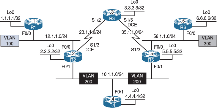
Figure 14-3 Configuring Auto-RP
Figure 14-3 illustrates the topology that will be used in the following lab.
Cisco developed a mechanism to dynamically elect and advertise the identity of a Rendezvous Point. This mechanism has several components and will be explored in the following lab.
Task 1
Configure OSPF Area 0 on all interfaces.
On All Routers:
Rx(config)# router ospf 1
Rx(config-router)# network 0.0.0.0 0.0.0.0 area 0
Let’s verify the configuration:
On R1:
R1# show ip route ospf | begin Gate
Gateway of last resort is not set
2.0.0.0/32 is subnetted, 1 subnets
O 2.2.2.2 [110/2] via 12.1.1.2, 00:00:18, FastEthernet0/0
3.0.0.0/32 is subnetted, 1 subnets
O 3.3.3.3 [110/783] via 12.1.1.2, 00:00:18, FastEthernet0/0
4.0.0.0/32 is subnetted, 1 subnets
O 4.4.4.4 [110/3] via 12.1.1.2, 00:00:08, FastEthernet0/0
5.0.0.0/32 is subnetted, 1 subnets
O 5.5.5.5 [110/3] via 12.1.1.2, 00:00:08, FastEthernet0/0
6.0.0.0/32 is subnetted, 1 subnets
O 6.6.6.6 [110/4] via 12.1.1.2, 00:00:08, FastEthernet0/0
10.0.0.0/24 is subnetted, 1 subnets
O 10.1.1.0 [110/2] via 12.1.1.2, 00:00:08, FastEthernet0/0
23.0.0.0/24 is subnetted, 1 subnets
O 23.1.1.0 [110/782] via 12.1.1.2, 00:00:18, FastEthernet0/0
35.0.0.0/24 is subnetted, 1 subnets
O 35.1.1.0 [110/783] via 12.1.1.2, 00:00:08, FastEthernet0/0
56.0.0.0/24 is subnetted, 1 subnets
O 56.1.1.0 [110/3] via 12.1.1.2, 00:00:08, FastEthernet0/0
Task 2
Configure PIM sparse-dense-mode on all the interfaces in this topology:
On R1:
R1(config)# ip multicast-routing
R1(config)# interface loopback0
R1(config-if)# ip pim sparse-dense-mode
R1(config-if)# interface FastEthernet0/0
R1(config-if)# ip pim sparse-dense-mode
On R2:
R2(config)# ip multicast-routing
R2(config)# interface loopback0
R2(config-if)# ip pim sparse-dense-mode
R2(config)# interface FastEthernet0/0
R2(config-if)# ip pim sparse-dense-mode
R2(config)# interface FastEthernet0/1
R2(config-if)# ip pim sparse-dense-mode
R2(config)# interface serial1/3
R2(config-if)# ip pim sparse-dense-mode
On R3:
R3(config)# ip multicast-routing
R3(config)# interface loopback0
R3(config-if)# ip pim sparse-dense-mode
R3(config)# interface serial1/2
R3(config-if)# ip pim sparse-dense-mode
R3(config)# interface serial1/5
R3(config-if)# ip pim sparse-dense-mode
On R4:
R4(config)# ip multicast-routing
R4(config)# interface loopback0
R4(config-if)# ip pim sparse-dense-mode
R4(config)# interface FastEthernet0/1
R4(config-if)# ip pim sparse-dense-mode
On R5:
R5(config)# ip multicast-routing
R5(config)# interface loopback0
R5(config-if)# ip pim sparse-dense-mode
R5(config)# interface FastEthernet0/0
R5(config-if)# ip pim sparse-dense-mode
R5(config)# interface FastEthernet0/1
R5(config-if)# ip pim sparse-dense-mode
R5(config-)# interface serial1/3
R5(config-if)# ip pim sparse-dense-mode
On R6:
R6(config)# ip multicast-routing
R6(config)# interface loopback0
R6(config-if)# ip pim sparse-dense-mode
R6(config-if)# interface FastEthernet0/0
R6(config-if)# ip pim sparse-dense-mode
Let’s verify the configuration:
On R1:
R1# show ip pim neighbor | begin Interface
Neighbor Interface Uptime/Expires Ver DR
Address Prio/Mode
12.1.1.2 FastEthernet0/0 00:03:20/00:01:20 v2 1 / DR S P G
On R2:
R2# show ip pim neighbor | begin Interface
Neighbor Interface Uptime/Expires Ver DR
Address Prio/Mode
12.1.1.1 FastEthernet0/0 00:04:30/00:01:40 v2 1 / S P G
10.1.1.5 FastEthernet0/1 00:02:15/00:01:26 v2 1 / DR S P G
10.1.1.4 FastEthernet0/1 00:03:02/00:01:26 v2 1 / S P G
23.1.1.3 Serial1/3 00:03:41/00:01:29 v2 1 / S P G
On R3:
R3# show ip pim neighbor | begin Interface
Neighbor Interface Uptime/Expires Ver DR
Address Prio/Mode
23.1.1.2 Serial1/2 00:03:41/00:01:29 v2 1 / S P G
35.1.1.5 Serial1/5 00:02:26/00:01:16 v2 1 / S P G
On R4:
R4# show ip pim neighbor | begin Interface
Neighbor Interface Uptime/Expires Ver DR
Address Prio/Mode
10.1.1.5 FastEthernet0/1 00:02:15/00:01:26 v2 1 / DR S P G
10.1.1.2 FastEthernet0/1 00:03:02/00:01:27 v2 1 / S P G
On R5:
R5# show ip pim neighbor | begin Interface
Neighbor Interface Uptime/Expires Ver DR
Address Prio/Mode
35.1.1.3 Serial1/3 00:02:26/00:01:16 v2 1 / S P G
56.1.1.6 FastEthernet0/0 00:02:20/00:01:21 v2 1 / DR S P G
10.1.1.2 FastEthernet0/1 00:02:15/00:01:27 v2 1 / S P G
10.1.1.4 FastEthernet0/1 00:02:15/00:01:26 v2 1 / S P G
On R6:
R6# show ip pim neighbor | begin Interface
Neighbor Interface Uptime/Expires Ver DR
Address Prio/Mode
56.1.1.5 FastEthernet0/0 00:02:20/00:01:22 v2 1 / S P
Task 3
Configure R4 as the primary RP for 238.0.0.0/8 and R3 as the backup RP. You should use Auto-RP to distribute the RP mapping information through R5.
In Auto-RP, two roles must be defined:
![]() Candidate RPs: The routers configured to be the RP will announce themselves as the RP for all or specific groups. They accomplish this by sending RP-announce messages. The destination address of these announcements is 224.0.1.39. All routers will hear these announcements, but only the router configured as the mapping agent will process them.
Candidate RPs: The routers configured to be the RP will announce themselves as the RP for all or specific groups. They accomplish this by sending RP-announce messages. The destination address of these announcements is 224.0.1.39. All routers will hear these announcements, but only the router configured as the mapping agent will process them.
![]() Mapping agent: The router that is configured to be the mapping agent will process the RP-announce messages and decide the RP-to-group mapping. If there is more than one RP announcement for a given group, the mapping agent will elect the RP with the highest source IP address as the RP for that group; this behavior cannot be changed. The MA will send RP-discover messages to announce the RP-to-group mapping.
Mapping agent: The router that is configured to be the mapping agent will process the RP-announce messages and decide the RP-to-group mapping. If there is more than one RP announcement for a given group, the mapping agent will elect the RP with the highest source IP address as the RP for that group; this behavior cannot be changed. The MA will send RP-discover messages to announce the RP-to-group mapping.
We need to explore the caveats and rational behind how Auto-RP works. This extends into its functionality and its operational requirements.
![]() Why sparse-dense-mode? Because 224.0.1.39 and 224.0.1.40 can only work in dense-mode, configuring sparse-mode will not work. Therefore, sparse-dense-mode is required for Auto-RP configuration.
Why sparse-dense-mode? Because 224.0.1.39 and 224.0.1.40 can only work in dense-mode, configuring sparse-mode will not work. Therefore, sparse-dense-mode is required for Auto-RP configuration.
Auto-RP can work with interfaces configured as sparse-mode only if the routers are configured with ip pim autorp listener.
![]() Why do these groups have to operate in dense-mode? In Auto-RP, the multicast packets are forwarded on the shared tree, which means that the routers need to be aware of the RP. The router that’s listening for 224.0.1.40 should notify its RP that it needs to join 224.0.1.40 so it can receive and process the RP-discover messages, but the big question is how would that router know where the RP is if it has not received the RP-discover messages for that specific group? In other words, to join the group, the router needs to know the RP, but to know the RP, it needs to join the group.
Why do these groups have to operate in dense-mode? In Auto-RP, the multicast packets are forwarded on the shared tree, which means that the routers need to be aware of the RP. The router that’s listening for 224.0.1.40 should notify its RP that it needs to join 224.0.1.40 so it can receive and process the RP-discover messages, but the big question is how would that router know where the RP is if it has not received the RP-discover messages for that specific group? In other words, to join the group, the router needs to know the RP, but to know the RP, it needs to join the group.
The ip pim sparse-dense-mode command was created to fix this problem for groups 224.0.1.39 and 224.0.1.40. Remember that in sparse-dense-mode configuration, if the RP is known for the group, the interfaces use sparse-mode; however, if the RP is not known, they will use dense-mode.
In this task, both R3 and R4 should advertise themselves as the RP for the specific group, and R5 will be configured to collect the RP announcements and decide which router will be the primary RP and which will be the backup RP.
On R3:
R3# show access-lists
R3(config)# access-list 1 permit 238.0.0.0 0.255.255.255
R3(config)# ip pim send-rp-announce loopback0 scope 2 group-list 1
Note The group-list keyword limits the RP announcements only for the 238.0.0.0/8 group. The scope keyword defines the TTL of these packets, since it was not mentioned in the requirements; a scope of 2 was configured so only the mapping agent within this topology can receive the announcements.
In order for a router to use its loopback interface as the source IP address of RP-announce messages, multicast must be enabled on that loopback interface. If it’s not enabled, you will receive the following message:
Must first configure PIM mode on the interface: Loopback0
Note If you enter debug ip pim auto-rp before configuring the mapping agent, the following output will result every 60 seconds. This interval can be changed using the interval keyword on the ip pim send-rp-announce command.
Auto-RP(0): Build RP-Announce for 3.3.3.3, PIMv2/v1, ttl 2, ht 181
Auto-RP(0): Build announce entry for (238.0.0.0/8)
Auto-RP(0): Send RP-Announce packet of length 48 on Serial1/2
Auto-RP(0): Send RP-Announce packet of length 48 on Serial1/5
Auto-RP(0): Send RP-Announce packet of length 48 on Loopback0(*)
On R4:
R4# show access-lists
R4(config)# access-list 1 permit 238.0.0.0 0.255.255.255
R4(config)# ip pim send-rp-announce loopback0 scope 2 group-list 1
On R5:
R5(config)# ip pim send-rp-discovery loopback0 scope 5
Let’s verify the configuration:
On R1:
R1# show ip pim rp mapping
PIM Group-to-RP Mappings
Group(s) 238.0.0.0/8
RP 4.4.4.4 (?), v2v1
Info source: 5.5.5.5 (?), elected via Auto-RP
Uptime: 00:22:04, expires: 00:02:45
The output of the preceding show command reveals the following:
![]() R4 (4.4.4.4) is the RP for group 238.0.0.0/8.
R4 (4.4.4.4) is the RP for group 238.0.0.0/8.
![]() The ? indicates a failure in the name resolution.
The ? indicates a failure in the name resolution.
![]() The Info source section identifies the mapping agent (in this case, 5.5.5.5, or R5).
The Info source section identifies the mapping agent (in this case, 5.5.5.5, or R5).
![]() This election was managed by the Auto-RP process.
This election was managed by the Auto-RP process.
![]() The Uptime section shows the uptime of the existing RP for this multicast group.
The Uptime section shows the uptime of the existing RP for this multicast group.
![]() The expires section indicates the expiration time for the RP; this timer is refreshed when the local router receives the RP-Discovery messages, which occur every 60 seconds by default.
The expires section indicates the expiration time for the RP; this timer is refreshed when the local router receives the RP-Discovery messages, which occur every 60 seconds by default.
Let’s verify the name resolution (the second bullet point from the preceding explanation):
On R1:
R1(config)# ip host R4 4.4.4.4
R1(config)# ip host R5 5.5.5.5
R1# show ip pim rp mapping
PIM Group-to-RP Mappings
Group(s) 238.0.0.0/8
RP 4.4.4.4 (R4), v2v1
Info source: 5.5.5.5 (R5), elected via Auto-RP
Uptime: 00:03:34, expires: 00:02:24
On R2:
R2# show ip pim rp mapping
PIM Group-to-RP Mappings
Group(s) 238.0.0.0/8
RP 4.4.4.4 (?), v2v1
Info source: 5.5.5.5 (?), elected via Auto-RP
Uptime: 00:21:52, expires: 00:02:19
On R3:
R3# show ip pim rp mapping
PIM Group-to-RP Mappings
This system is an RP (Auto-RP)
Group(s) 238.0.0.0/8
RP 4.4.4.4 (?), v2v1
Info source: 5.5.5.5 (?), elected via Auto-RP
Uptime: 00:22:17, expires: 00:02:52
On R4:
R4# show ip pim rp mapping
PIM Group-to-RP Mappings
This system is an RP (Auto-RP)
Group(s) 238.0.0.0/8
RP 4.4.4.4 (?), v2v1
Info source: 5.5.5.5 (?), elected via Auto-RP
Uptime: 00:22:51, expires: 00:02:18
On R5:
R5# show ip pim rp mapping
PIM Group-to-RP Mappings
This system is an RP-mapping agent (Loopback0)
Group(s) 238.0.0.0/8
RP 4.4.4.4 (?), v2v1
Info source: 4.4.4.4 (?), elected via Auto-RP
Uptime: 01:12:09, expires: 00:02:55
RP 3.3.3.3 (?), v2v1
Info source: 3.3.3.3 (?), via Auto-RP Source IP address.
Uptime: 01:10:50, expires: 00:02:12
Note R5 (the MA) is aware of both RPs, but it elected R4 (4.4.4.4) because it has a higher IP address. After making this decision, it advertises R4 to the rest of the routers in RP-Discovery messages.
Let’s test the backup RP:
On R4:
R4(config)# interface loopback0
R4(config-if)# shutdown
Note The expires counter is counting down. Because R4 is down, R5 (the MA) will not receive the RP-announce messages; therefore, the counter expires and the entry is removed, as follows:
R5# show ip pim rp mapping | section 4.4.4.4
RP 4.4.4.4 (?), v2v1
Info source: 4.4.4.4 (?), elected via Auto-RP
Uptime: 00:25:32, expires: 00:02:27
R5# show ip pim rp mapping | section 4.4.4.4
RP 4.4.4.4 (?), v2v1
Info source: 4.4.4.4 (?), elected via Auto-RP
Uptime: 00:26:11, expires: 00:01:49
R5# show ip pim rp mapping | section 4.4.4.4
RP 4.4.4.4 (?), v2v1
Info source: 4.4.4.4 (?), elected via Auto-RP
Uptime: 00:26:40, expires: 00:01:19
R5# show ip pim rp mapping | section 4.4.4.4
RP 4.4.4.4 (?), v2v1
Info source: 4.4.4.4 (?), elected via Auto-RP
Uptime: 00:27:02, expires: 00:00:58
R5# show ip pim rp mapping | section 4.4.4.4
RP 4.4.4.4 (?), v2v1
Info source: 4.4.4.4 (?), elected via Auto-RP
Uptime: 00:27:48, expires: 00:00:11
R5# show ip pim rp mapping | section 4.4.4.4
RP 4.4.4.4 (?), v2v1
Info source: 4.4.4.4 (?), elected via Auto-RP
Uptime: 00:27:55, expires: 00:00:04
R5# show ip pim rp mapping | section 4.4.4.4
RP 4.4.4.4 (?), v2v1
Info source: 4.4.4.4 (?), elected via Auto-RP
Uptime: 00:27:59, expires: 00:00:01
R5# show ip pim rp mapping | section 4.4.4.4
R5# show ip pim rp mapping
PIM Group-to-RP Mappings
This system is an RP-mapping agent (Loopback0)
Group(s) 238.0.0.0/8
RP 3.3.3.3 (?), v2v1
Info source: 3.3.3.3 (?), elected via Auto-RP Uptime: 00:31:26, expires: 00:02:34
Finally, the entry has expired and has been removed; therefore, R3 (3.3.3.3) is the RP for groups in the 238.0.0.0/8 range. If the Lo0 interface of R4 is brought back up, it should once again resume its role as the primary RP. Let’s test this:
On R4:
R4(config)# interface loopback0
R4(config-if)# no shutdown
It may take up to 3 minutes for 3.3.3.3 information to show up in the output of the following show command:
On R5:
R5# show ip pim rp mapping
PIM Group-to-RP Mappings
This system is an RP-mapping agent (Loopback0)
Group(s) 238.0.0.0/8
RP 4.4.4.4 (?), v2v1
Info source: 4.4.4.4 (?), elected via Auto-RP
Uptime: 00:00:05, expires: 00:02:50
RP 3.3.3.3 (?), v2v1
Info source: 3.3.3.3 (?), via Auto-RP
Uptime: 00:18:20, expires: 00:00:15
Task 4
Configure R5 such that R6 does not receive the RP announcements.
Let’s view the RP mapping on R6 before the configuration:
On R6:
R6# show ip pim rp mapping
PIM Group-to-RP Mappings
Group(s) 238.0.0.0/8
RP 4.4.4.4 (?), v2v1
Info source: 5.5.5.5 (?), elected via Auto-RP
Uptime: 00:01:25, expires: 00:02:31
The output of the preceding show command reveals that R6 receives the RP mapping information from R5 (the MA). The following steps configure filtering of these announcements.
First, configure an access list to deny 224.0.1.40 and permit any:
R5# show access-lists
R5(config)# access-list 1 deny host 224.0.1.40
R5(config)# access-list 1 permit any
Once the access list is configured, you should apply it to the interface facing R6 (in this case, the F0/0 interface). In this configuration, the ip multicast boundary command is used. This command sets a boundary for administratively scoped multicast addresses. The purpose of this boundary is to restrict the flooding of multicast packets, especially in asymmetrical networks.
R5(config)# interface FastEthernet0/0
R5(config-if)# ip multicast boundary 1
Let’s verify the configuration.
Note R5 will no longer send the RP-Discovery messages to R6, and as a result of that, the RP mapping will expire, as shown here:
On R6:
R6# show ip pim rp mapping
PIM Group-to-RP Mappings
Group(s) 238.0.0.0/8
RP 4.4.4.4 (?), v2v1
Info source: 5.5.5.5 (?), elected via Auto-RP
Uptime: 00:02:19, expires: 00:02:37
R6# show ip pim rp mapping
PIM Group-to-RP Mappings
Group(s) 238.0.0.0/8
RP 4.4.4.4 (?), v2v1
Info source: 5.5.5.5 (?), elected via Auto-RP
Uptime: 00:02:59, expires: 00:01:57
R6# show ip pim rp mapping
PIM Group-to-RP Mappings
Group(s) 238.0.0.0/8
RP 4.4.4.4 (?), v2v1
Info source: 5.5.5.5 (?), elected via Auto-RP
Uptime: 00:04:28, expires: 00:00:28
R6# show ip pim rp mapping
PIM Group-to-RP Mappings
Group(s) 238.0.0.0/8
RP 4.4.4.4 (?), v2v1
Info source: 5.5.5.5 (?), elected via Auto-RP
Uptime: 00:04:54, expires: 00:00:03
R6# show ip pim rp mapping
PIM Group-to-RP Mappings
Once the timer expires, R6 will no longer have the RP mappings.
Task 5
Configure R3 to be the RP for 224.1.1.1 only.
Since the task states “only,” you must remove the previously configured access list and configure a new one to permit 224.1.1.1:
On R3:
R3(config)# no access-list 1
R3(config)# access-list 1 permit host 224.1.1.1
R3# show ip pim rp mapping
PIM Group-to-RP Mappings
This system is an RP (Auto-RP)
Group(s) 224.0.0.0/4
RP 3.3.3.3 (?), v2v1
Info source: 5.5.5.5 (?), elected via Auto-RP
Uptime: 00:00:18, expires: 00:02:52
Group(s) 224.1.1.1/32
RP 3.3.3.3 (?), v2v1
Info source: 5.5.5.5 (?), elected via Auto-RP
Uptime: 00:00:08, expires: 00:02:50
Group(s) 238.0.0.0/8
RP 4.4.4.4 (?), v2v1
Info source: 5.5.5.5 (?), elected via Auto-RP
Uptime: 00:12:51, expires: 00:02:49
On R1:
R1# show ip pim rp mapping
PIM Group-to-RP Mappings
Group(s) 224.0.0.0/4
RP 3.3.3.3 (?), v2v1
Info source: 5.5.5.5 (R5), elected via Auto-RP
Uptime: 00:01:22, expires: 00:01:48
Group(s) 224.1.1.1/32
RP 3.3.3.3 (?), v2v1
Info source: 5.5.5.5 (R5), elected via Auto-RP
Uptime: 00:01:12, expires: 00:02:58
Group(s) 238.0.0.0/8
RP 4.4.4.4 (R4), v2v1
Info source: 5.5.5.5 (R5), elected via Auto-RP
Uptime: 00:13:55, expires: 00:02:58
Task 6
Configure the Lo0 interface of R1 to join the group 224.1.1.1. This router should be configured such that it responds to pings generated by all routers in this topology:
On R1:
R1(config)# interface loopback0
R1(config-if)# ip igmp join-group 224.1.1.1
On R2:
R2# ping 224.1.1.1
Type escape sequence to abort.
Sending 1, 100-byte ICMP Echos to 224.1.1.1, timeout is 2 seconds:
Reply to request 0 from 1.1.1.1, 4 ms
Reply to request 0 from 1.1.1.1, 8 ms
On R3:
R3# ping 224.1.1.1
Type escape sequence to abort.
Sending 1, 100-byte ICMP Echos to 224.1.1.1, timeout is 2 seconds:
Reply to request 0 from 1.1.1.1, 32 ms
Reply to request 0 from 1.1.1.1, 44 ms
Reply to request 0 from 1.1.1.1, 32 ms
On R4:
R4# ping 224.1.1.1
Type escape sequence to abort.
Sending 1, 100-byte ICMP Echos to 224.1.1.1, timeout is 2 seconds:
Reply to request 0 from 1.1.1.1, 4 ms
Reply to request 0 from 1.1.1.1, 4 ms
On R5:
R5# ping 224.1.1.1
Type escape sequence to abort.
Sending 1, 100-byte ICMP Echos to 224.1.1.1, timeout is 2 seconds:
Reply to request 0 from 1.1.1.1, 4 ms
Reply to request 0 from 1.1.1.1, 32 ms
Reply to request 0 from 1.1.1.1, 4 ms
On R6:
R6# ping 224.1.1.1
Type escape sequence to abort.
Sending 1, 100-byte ICMP Echos to 224.1.1.1, timeout is 2 seconds:
.
!Since Auto-RP will not work on R6, as RP-Discovery messages are blocked by R5,
!static RP mapping is implemented as the solution to this task.
On R6:
R6# show access-lists
R6(config)# access-list 1 permit host 224.1.1.1
R6(config)# ip pim rp-address 3.3.3.3 1
R6# ping 224.1.1.1
Type escape sequence to abort.
Sending 1, 100-byte ICMP Echos to 224.1.1.1, timeout is 2 seconds:
Reply to request 0 from 1.1.1.1, 52 ms
Reply to request 0 from 1.1.1.1, 72 ms
Task 7
Configure the Lo0 interface of R1 to join group 224.10.10.10. This router should be configured such that it responds to pings generated by all routers in this topology:
On R1:
R1(config-if)# interface loopback0
R1(config-if)# ip igmp join-group 224.10.10.10
Let’s verify the configuration:
On R1:
R1# show ip igmp groups
IGMP Connected Group Membership
Group Address Interface Uptime Expires Last Reporter Group Accounted
224.10.10.10 Loopback0 00:00:10 00:02:49 1.1.1.1
224.1.1.1 Loopback0 00:05:19 00:02:41 1.1.1.1
224.0.1.40 Loopback0 01:11:23 00:02:37 1.1.1.1
Now we can test the configuration:
On R2:
R2# ping 224.10.10.10
Type escape sequence to abort.
Sending 1, 100-byte ICMP Echos to 224.10.10.10, timeout is 2 seconds:
Reply to request 0 from 1.1.1.1, 4 ms
Reply to request 0 from 1.1.1.1, 12 ms
On R3:
R3# ping 224.10.10.10
Type escape sequence to abort.
Sending 1, 100-byte ICMP Echos to 224.10.10.10, timeout is 2 seconds:
Reply to request 0 from 1.1.1.1, 32 ms
Reply to request 0 from 1.1.1.1, 44 ms
Reply to request 0 from 1.1.1.1, 32 ms
On R4:
R4# ping 224.10.10.10
Type escape sequence to abort.
Sending 1, 100-byte ICMP Echos to 224.10.10.10, timeout is 2 seconds:
Reply to request 0 from 1.1.1.1, 4 ms
Reply to request 0 from 1.1.1.1, 8 ms
On R5:
R5# ping 224.10.10.10
Type escape sequence to abort.
Sending 1, 100-byte ICMP Echos to 224.10.10.10, timeout is 2 seconds:
Reply to request 0 from 1.1.1.1, 4 ms
Reply to request 0 from 1.1.1.1, 8 ms
On R6:
R6# ping 224.10.10.10
Type escape sequence to abort.
Sending 1, 100-byte ICMP Echos to 224.10.10.10, timeout is 2 seconds:
Reply to request 0 from 1.1.1.1, 4 ms
Reply to request 0 from 1.1.1.1, 8 ms
R6# show ip mroute | s 224.10.10.10
(*, 224.10.10.10), 00:08:37/00:00:45, RP 0.0.0.0, flags: D
Incoming interface: Null, RPF nbr 0.0.0.0
Outgoing interface list:
FastEthernet0/0, Forward/Sparse-Dense, 00:02:00/stopped
(The rest of the output is omitted for brevity)
Note R6 was able to reach 224.10.10.10 because the interface of this router is configured as sparse-dense-mode. By default, when an interface is configured with ip pim sparse-dense-mode, the router will use PIM sparse mode (SM) for groups it has an RP mappings for and use PIM dense mode (DM) for groups it does not. In the event of an RP failure, all traffic will be dense mode forwarded. This situation may be undesirable and can be prevented with the use of the no ip pim dm-fallback command. We explore this feature in the following task.
Task 8
Configure the routers to disable the use of PIM DM for groups with no RP:
On All Routers:
Rx(config)# no ip pim dm-fallback
Let’s test the configuration:
On R2:
R2# ping 224.10.10.10
Type escape sequence to abort.
Sending 1, 100-byte ICMP Echos to 224.10.10.10, timeout is 2 seconds:
.
On R3:
R3# ping 224.10.10.10
Type escape sequence to abort.
Sending 1, 100-byte ICMP Echos to 224.10.10.10, timeout is 2 seconds:
.
On R4:
R4# ping 224.10.10.10
Type escape sequence to abort.
Sending 1, 100-byte ICMP Echos to 224.10.10.10, timeout is 2 seconds:
.
On R5:
R5# ping 224.10.10.10
Type escape sequence to abort.
Sending 1, 100-byte ICMP Echos to 224.10.10.10, timeout is 2 seconds:
.
On R6:
R6# ping 224.10.10.10
Type escape sequence to abort.
Sending 1, 100-byte ICMP Echos to 224.10.10.10, timeout is 2 seconds:
.
The pings failed because there are no RPs for 224.10.10.10 group.
Let’s test the configuration further:
On All Routers
Rx(config)# ip pim dm-fallback
On R2:
R2# ping 224.10.10.10
Type escape sequence to abort.
Sending 1, 100-byte ICMP Echos to 224.10.10.10, timeout is 2 seconds:
Reply to request 0 from 1.1.1.1, 8 ms
Reply to request 0 from 1.1.1.1, 48 ms
On R3:
R3# ping 224.10.10.10
Type escape sequence to abort.
Sending 1, 100-byte ICMP Echos to 224.10.10.10, timeout is 2 seconds:
Reply to request 0 from 1.1.1.1, 144 ms
Reply to request 0 from 1.1.1.1, 200 ms
Reply to request 0 from 1.1.1.1, 160 ms
On R4:
R4# ping 224.10.10.10
Type escape sequence to abort.
Sending 1, 100-byte ICMP Echos to 224.10.10.10, timeout is 2 seconds:
Reply to request 0 from 1.1.1.1, 44 ms
Reply to request 0 from 1.1.1.1, 72 ms
On R5:
R5# ping 224.10.10.10
Type escape sequence to abort.
Sending 1, 100-byte ICMP Echos to 224.10.10.10, timeout is 2 seconds:
Reply to request 0 from 1.1.1.1, 44 ms
Reply to request 0 from 1.1.1.1, 72 ms
On R6:
R6# ping 224.10.10.10
Type escape sequence to abort.
Sending 1, 100-byte ICMP Echos to 224.10.10.10, timeout is 2 seconds:
Reply to request 0 from 1.1.1.1, 72 ms
Reply to request 0 from 1.1.1.1, 72 ms
Erase the startup configuration of the routers and SW1 and reload them before proceeding to the next lab.
Lab 14-4: Bootstrap Router (BSR)
Figure 14-4 Configuring Boot Strap Router
Figure 14-4 illustrates the topology that will be used in the following lab.
Task 1
Configure OSPF Area 0 on all interfaces:
On All Routers:
Rx(config)# router ospf 1
Rx(config-router)# network 0.0.0.0 0.0.0.0 area 0
Let’s verify the configuration:
On R1:
R1# show ip route ospf | begin Gate
Gateway of last resort is not set
2.0.0.0/32 is subnetted, 1 subnets
O 2.2.2.2 [110/2] via 12.1.1.2, 00:00:18, FastEthernet0/0
3.0.0.0/32 is subnetted, 1 subnets
O 3.3.3.3 [110/783] via 12.1.1.2, 00:00:18, FastEthernet0/0
4.0.0.0/32 is subnetted, 1 subnets
O 4.4.4.4 [110/3] via 12.1.1.2, 00:00:08, FastEthernet0/0
5.0.0.0/32 is subnetted, 1 subnets
O 5.5.5.5 [110/3] via 12.1.1.2, 00:00:08, FastEthernet0/0
6.0.0.0/32 is subnetted, 1 subnets
O 6.6.6.6 [110/4] via 12.1.1.2, 00:00:08, FastEthernet0/0
10.0.0.0/24 is subnetted, 1 subnets
O 10.1.1.0 [110/2] via 12.1.1.2, 00:00:08, FastEthernet0/0
23.0.0.0/24 is subnetted, 1 subnets
O 23.1.1.0 [110/782] via 12.1.1.2, 00:00:18, FastEthernet0/0
35.0.0.0/24 is subnetted, 1 subnets
O 35.1.1.0 [110/783] via 12.1.1.2, 00:00:08, FastEthernet0/0
56.0.0.0/24 is subnetted, 1 subnets
O 56.1.1.0 [110/3] via 12.1.1.2, 00:00:08, FastEthernet0/0
Task 2
Configure pim sparse-mode on all the interfaces in this topology:
On R1:
R1(config)# ip multicast-routing
R1(config)# interface loopback0
R1(config-if)# ip pim sparse-mode
R1(config-if)# interface FastEthernet0/0
R1(config-if)# ip pim sparse-mode
On R2:
R2(config)# ip multicast-routing
R2(config)# interface loopback0
R2(config-if)# ip pim sparse-mode
R2(config)# interface FastEthernet0/0
R2(config-if)# ip pim sparse-mode
R2(config)# interface FastEthernet0/1
R2(config-if)# ip pim sparse-mode
R2(config)# interface serial1/3
R2(config-if)# ip pim sparse-mode
On R3:
R3(config)# ip multicast-routing
R3(config)# interface loopback0
R3(config-if)# ip pim sparse-mode
R3(config)# interface serial1/2
R3(config-if)# ip pim sparse-mode
R3(config)# interface serial1/5
R3(config-if)# ip pim sparse-mode
On R4:
R4(config)# ip multicast-routing
R4(config)# interface loopback0
R4(config-if)# ip pim sparse-mode
R4(config)# interface FastEthernet0/1
R4(config-if)# ip pim sparse-mode
On R5:
R5(config)# ip multicast-routing
R5(config)# interface loopback0
R5(config-if)# ip pim sparse-mode
R5(config)# interface FastEthernet0/0
R5(config-if)# ip pim sparse-mode
R5(config)# interface FastEthernet0/1
R5(config-if)# ip pim sparse-mode
R5(config)# interface serial1/3
R5(config-if)# ip pim sparse-mode
On R6:
R6(config)# ip multicast-routing
R6(config)# interface loopback0
R6(config-if)# ip pim sparse-mode
R6(config)# interface FastEthernet0/0
R6(config-if)# ip pim sparse-mode
Let’s verify the configuration:
On R1:
R1# show ip pim neighbor | begin Interface
Neighbor Interface Uptime/Expires Ver DR
Address Prio/Mode
12.1.1.2 FastEthernet0/0 00:03:42/00:01:29 v2 1 / DR S P G
On R2:
R2# show ip pim neighbor | begin Interface
Neighbor Interface Uptime/Expires Ver DR
Address Prio/Mode
12.1.1.1 FastEthernet0/0 00:03:42/00:01:28 v2 1 / S P G
10.1.1.5 FastEthernet0/1 00:01:28/00:01:15 v2 1 / DR S P G
10.1.1.4 FastEthernet0/1 00:02:03/00:01:15 v2 1 / S P G
23.1.1.3 Serial1/3 00:03:06/00:01:36 v2 1 / S P G
On R3:
R3# show ip pim neighbor | begin Interface
Neighbor Interface Uptime/Expires Ver DR
Address Prio/Mode
23.1.1.2 Serial1/2 00:03:06/00:01:36 v2 1 / S P G
35.1.1.5 Serial1/5 00:01:33/00:01:40 v2 1 / S P G
On R4:
R4# show ip pim neighbor | begin Interface
Neighbor Interface Uptime/Expires Ver DR
Address Prio/Mode
10.1.1.5 FastEthernet0/1 00:01:28/00:01:15 v2 1 / DR S P G
10.1.1.2 FastEthernet0/1 00:02:03/00:01:15 v2 1 / S P G
On R5:
R5# show ip pim neighbor
Neighbor Interface Uptime/Expires Ver DR
Address Prio/Mode
35.1.1.3 Serial1/3 00:01:33/00:01:40 v2 1 / S P G
10.1.1.2 FastEthernet0/1 00:01:28/00:01:15 v2 1 / S P G
10.1.1.4 FastEthernet0/1 00:01:28/00:01:15 v2 1 / S P G
56.1.1.6 FastEthernet0/0 00:00:23/00:01:20 v2 1 / DR S P G
On R6:
R6# show ip pim neighbor
Neighbor Interface Uptime/Expires Ver DR
Address Prio/Mode
56.1.1.5 FastEthernet0/0 00:00:23/00:01:20 v2 1 / S P G
Task 3
Configure R3 and R4 as the RP for all groups; R3 should be the primary and R4 should be the backup. These routers should use their Lo0’s IP address as the source of their announcements every 30 seconds. You should not change the PIM mode or change the IP addressing of the interface(s) to accomplish this task.
The following are the possible choices:
![]() Auto-RP
Auto-RP
![]() Static RP
Static RP
![]() BSR
BSR
![]() Anycast RP
Anycast RP
To resolve this task, Auto-RP or static RP cannot be used because R4 has a higher IP address and it will always be chosen as the primary RP. Therefore, BSR is the only choice.
The question should be where to place the bootstrap routers. The answer is, any two routers. Why two? Well, the task asks for a redundant mapping.
In the following solution, RP candidates are also configured as the BSRs. A debug ip pim bsr command is configured to see the messages generated by the RP and the BSR.
On R3:
R3# debug ip pim bsr
PIM-BSR debugging is on
R3(config)# ip pim rp-candidate loopback0 interval 30
You should see the following debug output on your console:
PIM-BSR(0): Build v2 Candidate-RP advertisement for 3.3.3.3 priority 0, holdtime 150
PIM-BSR(0): Candidate RP's group prefix 224.0.0.0/4
PIM-BSR(0): no bootstrap router address
Note The advertisements are generated from the IP address of the loopback0 interface. The priority is set to zero and the holdtime is set to 150. The holdtime is 2.5 times the interval in which these messages are generated; by default these messages are generated every 60 seconds. Because a BSR is not configured, the last line of the debug states that the local router does not see a BSR.
Let’s configure the BSR:
R3(config)# ip pim bsr-candidate loopback0
PIM-BSR(0): Build v2 Candidate-RP advertisement for 3.3.3.3 priority 0,
holdtime 150
PIM-BSR(0): Candidate RP's group prefix 224.0.0.0/4
PIM-BSR(0): Send Candidate RP Advertisement to 3.3.3.3
PIM-BSR(0): RP 3.3.3.3, 1 Group Prefixes, Priority 0, Holdtime 150
PIM-BSR(0): RP-set for 224.0.0.0/4
PIM-BSR(0): RP(1) 3.3.3.3, holdtime 150 sec priority 0
PIM-BSR(0): Bootstrap message for 3.3.3.3 originated
Note Now that candidate RP knows the IP address of the BSR, it sends a unicast message to the bootstrap router to identify itself as a candidate RP.
In the following configuration, R4 is configured as candidate RP with a priority of 200, because a lower priority value has more preference; R3 is elected as the RP:
On R4:
R4(config)# ip pim rp-candidate loopback0 interval 30 priority 200
R4(config)# ip pim bsr-candidate loopback0
Contrary to RP election, where lower priority has more preference, in BSR election, the higher priority has more preference and the higher IP address is used as the tiebreaker.
Let’s verify the configuration:
On R3:
R3# undebug all
R3# show ip pim rp mapping
PIM Group-to-RP Mappings
This system is a candidate RP (v2)
Group(s) 224.0.0.0/4
RP 3.3.3.3 (?), v2
Info source: 4.4.4.4 (?), via bootstrap, priority 0, holdtime 150
Uptime: 00:06:14, expires: 00:02:06
RP 4.4.4.4 (?), v2
Info source: 4.4.4.4 (?), via bootstrap, priority 200, holdtime 150
Uptime: 00:04:26, expires: 00:02:05
R4 and R3 are both configured as Candidate-BSRs. By default, the priority of these routers is set to zero; therefore, the router with a higher source IP address (4.4.4.4 versus 3.3.3.3) is elected as the BSR.
Contrary to Auto-RP, in BSR, the C-BSR collects all RP announcements and creates a Rendezvous Point Set (RP-SET); the RP-SET is then advertised to all DRs.
Once the DRs receive the RP-SET, they will elect an RP from the list for a given group. Luckily, all DR routers use the same calculations to elect an RP; therefore, the result of the election will be consistent across all routers.
Let’s verify the configuration:
On R1:
R1# show ip pim rp mapping
PIM Group-to-RP Mappings
Group(s) 224.0.0.0/4
RP 3.3.3.3 (?), v2
Info source: 4.4.4.4 (?), via bootstrap, priority 0, holdtime 150
Uptime: 00:05:19, expires: 00:02:04
RP 4.4.4.4 (?), v2
Info source: 4.4.4.4 (?), via bootstrap, priority 200, holdtime 150
Uptime: 00:03:29, expires: 00:02:04
On R2:
R2# show ip pim rp mapping
PIM Group-to-RP Mappings
Group(s) 224.0.0.0/4
RP 3.3.3.3 (?), v2
Info source: 4.4.4.4 (?), via bootstrap, priority 0, holdtime 150
Uptime: 00:11:58, expires: 00:02:24
RP 4.4.4.4 (?), v2
Info source: 4.4.4.4 (?), via bootstrap, priority 200, holdtime 150
Uptime: 00:10:10, expires: 00:02:22
On R5:
R5# show ip pim rp mapping
PIM Group-to-RP Mappings
Group(s) 224.0.0.0/4
RP 3.3.3.3 (?), v2
Info source: 4.4.4.4 (?), via bootstrap, priority 0, holdtime 150
Uptime: 00:12:27, expires: 00:01:57
RP 4.4.4.4 (?), v2
Info source: 4.4.4.4 (?), via bootstrap, priority 200, holdtime 150
Uptime: 00:10:38, expires: 00:01:56
On R6:
R6# show ip pim rp mapping
PIM Group-to-RP Mappings
Group(s) 224.0.0.0/4
RP 3.3.3.3 (?), v2
Info source: 4.4.4.4 (?), via bootstrap, priority 0, holdtime 150
Uptime: 00:12:58, expires: 00:02:21
RP 4.4.4.4 (?), v2
Info source: 4.4.4.4 (?), via bootstrap, priority 200, holdtime 150
Uptime: 00:11:10, expires: 00:02:22
Let’s further verify the configuration:
On R1:
R1# show ip pim bsr-router
PIMv2 Bootstrap information
BSR address: 4.4.4.4 (?)
Uptime: 00:11:33, BSR Priority: 0, Hash mask length: 0
Expires: 00:01:36
On R2:
R2# show ip pim bsr-router
PIMv2 Bootstrap information
BSR address: 4.4.4.4 (?)
Uptime: 00:12:12, BSR Priority: 0, Hash mask length: 0
Expires: 00:01:57
On R3:
R3# show ip pim bsr-router
PIMv2 Bootstrap information
BSR address: 4.4.4.4 (?)
Uptime: 00:12:55, BSR Priority: 0, Hash mask length: 0
Expires: 00:01:14
This system is a candidate BSR
Candidate BSR address: 3.3.3.3, priority: 0, hash mask length: 0
Candidate RP: 3.3.3.3(Loopback0)
Holdtime 75 seconds
Advertisement interval 30 seconds
Next advertisement in 00:00:04
On R4:
R4# show ip pim bsr-router
PIMv2 Bootstrap information
This system is the Bootstrap Router (BSR)
BSR address: 4.4.4.4 (?)
Uptime: 00:12:13, BSR Priority: 0, Hash mask length: 0
Next bootstrap message in 00:00:47
Candidate RP: 4.4.4.4(Loopback0)
Holdtime 75 seconds
Advertisement interval 30 seconds
Next advertisement in 00:00:18
Candidate RP priority : 200
On R5:
R5# show ip pim bsr-router
PIMv2 Bootstrap information
BSR address: 4.4.4.4 (?)
Uptime: 00:12:12, BSR Priority: 0, Hash mask length: 0
Expires: 00:01:57
On R6:
R6# show ip pim bsr-router
PIMv2 Bootstrap information
BSR address: 4.4.4.4 (?)
Uptime: 00:12:12, BSR Priority: 0, Hash mask length: 0
Expires: 00:01:57
Task 4
Configure the Lo0 interface of R1 to join 239.1.1.1 and then ensure that R3, R4, and R5 can successfully ping this group:
On R1:
R1(config)# interface loopback0
R1(config-if)# ip igmp join-group 239.1.1.1
On R3:
R3# ping 239.1.1.1
Type escape sequence to abort.
Sending 1, 100-byte ICMP Echos to 239.1.1.1, timeout is 2 seconds:
Reply to request 0 from 1.1.1.1, 72 ms
Reply to request 0 from 1.1.1.1, 104 ms
Reply to request 0 from 1.1.1.1, 92 ms
On R4:
R4# ping 239.1.1.1
Type escape sequence to abort.
Sending 1, 100-byte ICMP Echos to 239.1.1.1, timeout is 2 seconds:
Reply to request 0 from 1.1.1.1, 4 ms
Reply to request 0 from 1.1.1.1, 20 ms
On R5:
R5# ping 239.1.1.1
Type escape sequence to abort.
Sending 1, 100-byte ICMP Echos to 239.1.1.1, timeout is 2 seconds:
Reply to request 0 from 1.1.1.1, 4 ms
Reply to request 0 from 1.1.1.1, 60 ms
Reply to request 0 from 1.1.1.1, 36 ms
Reply to request 0 from 1.1.1.1, 12 ms
On R5:
R5# show ip mroute | section 239.1.1.1
(*, 239.1.1.1), 00:01:52/stopped, RP 3.3.3.3, flags: SPF
Incoming interface: Serial1/3, RPF nbr 35.1.1.3
Outgoing interface list: Null
(The rest of the output is omitted for brevity)
As expected, the RP for the group is R3 because it has a lower RP priority.
Erase the startup configuration and reload the routers before proceeding to the next lab.