Chapter 4 Point-to-Point Protocol
Point-to-Point Protocol (PPP) is one of the most ubiquitous and arguably well-designed data-link layer protocols still in use. Originally designed for dialed and permanent point-to-point WAN links running over serial interfaces, PPP has been reused in a number of other protocols, such as PPTP, L2TP, and PPPoE. Despite its open nature and wide adoption, though, understanding of PPP operations is often superficial—an administrator usually just activates the PPP encapsulation and optionally configures authentication parameters. This chapter therefore provides a more involved insight into the workings of PPP.
Introduction to PPP
To understand why PPP has become so popular, we need to take a brief look into the history of WAN data-link layer protocols. In the late 1980s, just before PPP was created, there were already a number of data-link layer protocols that could be used over a physical point-to-point link, or at least could provide an emulation of a point-to-point link. The most prominent protocols were HDLC, SLIP, X.25, and Frame Relay. However, all these protocols had certain deficiencies. The first major drawback was the lack of control and management functions, such as negotiation of link operational parameters, a keepalive mechanism, peer authentication, detection of a looped link, negotiation of higher layer protocols to be transported across the link, and provisioning of configuration information to higher layer protocols. While these features might seem to be of marginal usefulness, they are extremely important from a service provider’s point of view, and we will have a closer look at them later in the chapter.
The second drawback was much more fundamental: As surprising as it may seem, the frame format of these protocols did not contain a field that would identify the protocol in the payload portion of the frame. In other words, based on the information present in the frame header alone, it was not possible to know what was being carried inside the frame’s payload—whether it was, say, an IPv4 packet or an IPv6 packet. This approach made sense in the past when there was usually only a single specific higher protocol carried over a link, so both peers statically configured for this protocol knew what to expect. However, if multiple higher protocols were to be used simultaneously over this link, frame headers did not carry the information necessary to tell these higher protocols apart. There were several methods envisioned to solve this problem, such as inserting IEEE 802.2 LLC, IEEE 802 SNAP, or ISO/IEC NLPID headers identifying the higher protocol into the frame payload along with the higher protocol packet itself, or assuming that the header of the higher protocol already contained a fixed field that uniquely identified it; however, none of these methods became mandatory, so the uncertainty remained. And as if this were not confusing enough, vendors sometimes decided to solve this problem in their own proprietary and incompatible ways by extending the frame formats themselves with an additional “Payload Type”-like field that, initially, was supported only by their own devices. This is the exact case with Cisco’s own formats of High-Level Data Link Control (HDLC) and Frame Relay framing.
The design of PPP removes these deficiencies, and adds a set of new useful features not seen with other data-link layer protocols. PPP is an open protocol whose core part is specified in RFCs 1661 and 1662 (the initial RFC was 1134), and additional features are described in various further RFCs. Although we will be talking about PPP running on Cisco routers in particular, at the time of its inception, PPP ran as a software driver on ordinary user computers, workstations, and servers, and only then gradually made its way into ISDN modems, integrated routers, and other network equipment. All discussion about PPP “between routers” should therefore be seen in this broader context as a PPP session between any two directly connected neighbors on a point-to-point link, regardless of what exact devices these neighbors are, as long as they support PPP.
PPP Frame Format
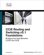
Interestingly enough, PPP does not specify its own entire frame format. Instead, for point-to-point serial links, it reuses the basic HDLC framing and defines additional header and trailer fields that will be added into the basic HDLC frame payload so that, together, they form a valid PPP frame in HDLC framing, as shown in Figure 4-1.
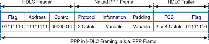
Figure 4-1 PPP Frame Format
The Flag, Address, and Control header fields are retained from the basic HDLC frame structure. The Flag field contains a constant value of 01111110 in binary, and serves as a frame delimiter to separate subsequent frames from each other. In a series of frames sent one after another, a single Flag field between individual frames can be used. The Address field for PPP is set to a constant value of 11111111 (the All-Stations address) in binary, regardless of the sender of the frame, because on a point-to-point link, unique data-link addresses have no meaning. The Control field is also set to a constant value of 00000011, indicating that this is an unnumbered information frame, one of three specific HDLC frame types that carry user information but are not delivered reliably (meaning no sequencing and no acknowledgements).
The Protocol field is a mandatory field present in every PPP frame. Being two octets long, this field identifies the type of higher protocol carried in the Information field. The purpose of the Protocol field is the same as the purpose of the EtherType field in Ethernet frames; however, perhaps somewhat unfortunately, PPP uses different values than Ethernet to enumerate higher protocols. For example, IPv4 uses an EtherType of 0x0800 but a PPP Protocol value of 0x0021; IPv6 uses an EtherType of 0x86DD but a PPP Protocol value of 0x0057. Nonetheless, the Protocol field is a fixed part of every PPP frame and hence it solves one of the major drawbacks of HDLC in terms of identifying the nature of its payload.
The Information field is the actual payload where the higher protocol datagram would be carried—and quite naturally, it is of a variable size. The Padding field allows the sender to artificially fill the frame with dummy bytes so that its size meets a prescribed minimum. Because frame padding is seldom used, the entire Padding field is optional. The “naked PPP frame,” therefore, usually consists just of the Protocol header field and the actual higher protocol packet.
The FCS field is the frame checksum computed over the Address, Control, Protocol, Information, and Payload fields (if present). By default, a 16-bit cyclic redundancy check (CRC) is used. It is possible to configure routers to use a 32-bit CRC if necessary.
PPP Control Plane
What truly distinguishes PPP from other similar data-link layer protocols is the fact that along with the framing (the PPP data plane), it comes with its own control plane and a dedicated set of control protocols. These PPP control plane protocols can be divided into two subgroups: the Link Control Protocol (LCP) and the Network Control Protocols (NCPs). LCP is a protocol that takes care of establishing a PPP session between two link partners. NCP is the name for a whole family of protocols that negotiate the transport of specific higher layer protocols over a PPP link and optionally provide configuration parameters to these higher protocols. Both LCP and NCP are carried inside PPP frames as their payload, and each of them uses a unique Protocol value.
Link Control Protocol and Basic PPP Session Establishment
A PPP session between two routers is established in three phases: Link Establishment Phase, Authentication Phase, and Network Layer Protocol Phase. The Link Establishment Phase is the first phase, during which two routers verify whether they speak PPP and negotiate the basic link operation parameters. The key protocol in charge of the Link Establishment Phase is the Link Control Protocol.
LCP is a protocol whose purpose is to set up and maintain a PPP session between routers. In particular, LCP performs the following tasks:
![]() It verifies that the routers speak PPP.
It verifies that the routers speak PPP.
![]() It verifies that the link is not looped (if the link is looped, the router will be talking to itself).
It verifies that the link is not looped (if the link is looped, the router will be talking to itself).
![]() It negotiates the basic parameters of the link operation, such as the maximum packet size a router is willing to receive, partner authentication, link quality monitoring, and Protocol and/or Address/Control header field compression.
It negotiates the basic parameters of the link operation, such as the maximum packet size a router is willing to receive, partner authentication, link quality monitoring, and Protocol and/or Address/Control header field compression.
![]() It periodically verifies the liveliness of the session.
It periodically verifies the liveliness of the session.
![]() It tears down the session if any of the routers decides to close it.
It tears down the session if any of the routers decides to close it.
During the Link Establishment Phase, LCP makes use of four Configure message types: Configure-Request, Configure-Ack, Configure-Nak, and Configure-Reject. Each of these messages contains a one-octet integer called Identification in its header, which is used to properly match a request and a corresponding response (Ack, Nak, or Reject).
The basic start of a PPP session is accomplished by each router sending PPP frames with an LCP Configure-Request (CONFREQ) message, as shown in Figure 4-2. This message may contain a list of options depending on what feature is being requested by a router from its neighbor. Among other options, a CONFREQ message usually contains a so-called magic number option, which is simply a random number generated by its sender. If a sender receives a CONFREQ with the same magic number it has sent itself, then either its neighbor has chosen the same magic number, or the link is looped and the sender is seeing its own frame. In such a case, each of the senders will choose another magic number and attempt another exchange of LCP packets. If the received magic numbers are still identical to the sent ones, it is with high probability an indication of a looped link. The number of attempts at arriving at a unique magic number and the reaction to an indication of a looped link is implementation-specific; PPP does not mandate any specific action. The magic number option is not mandatory and may be omitted; however, Cisco routers use it by default.
If a router receives a CONFREQ with a different magic number or no magic number at all, it analyzes the other options in the message. These options may include the maximum receive unit (MRU; the maximum packet size the neighbor is capable of receiving), authentication type, link quality monitoring, selected frame header field compression, and others. If the router recognizes all received options, is in agreement with all of them, and is willing to operate accordingly, it will respond with a Configure-Ack (CONFACK) message. This CONFACK will contain an exact copy of the entire body of the CONFREQ that is being acknowledged. If a router receives a CONFACK from its neighbor to its own CONFREQ, this indicates that the neighbor speaks PPP and fully agrees with all suggested link options. In the simplest case, a PPP session is bidirectionally established after each router both receives a CONFACK for its own CONFREQ and sends a CONFACK for the neighbor’s CONFREQ (four messages in total). Note that the precise order of these messages on the link may vary; a router usually sends out CONFREQ messages without waiting for its neighbor to send anything, and may confirm a received CONFREQ with a CONFACK right away, without waiting for its own CONFREQ to be confirmed by the neighbor. Figure 4-2 shows one particular possible ordering.
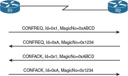
Figure 4-2 Basic LCP Message Exchange Between PPP Peers
If a router receives a CONFREQ with a different magic number or no magic number at all, as well as recognizes all options in the message but considers some of the option values unacceptable and open for negotiation (for example, the particular authentication method is not supported by the router but another method is), it will respond by sending back a Configure-Nak (CONFNAK) message, as shown in Figure 4-3. This CONFNAK will contain the list of all unacceptable options from the CONFREQ, and their values will be set to the router’s own acceptable values for these options. This way, the router negotiates alternative values for these options, hoping that its neighbor will still find them agreeable. If the neighbor receives a CONFNAK and is willing to adapt its own operation to the option values suggested by the router, it will resend a new CONFREQ with all options it has included previously, but for the contentious options, it will use the values as suggested in the received CONFNAK. If the neighbor is unwilling to adapt, then a deadlock ensues; the neighbor will resend a new CONFREQ with all options unchanged, prompting the same CONFNAK from the router as before, and the PPP session will not be established. The “ping-pong” of CONFREQ and CONFNAK messages will be throttled down but will continue until the configuration of either router is changed to match the neighbor or until the interface is brought down.
Figure 4-3 shows a situation where R1 and R2 are trying to bring up a link, and R2 requires that R1 prove its identity (that is, authenticate itself) to R2 using CHAP. R1, however, does not support CHAP and suggests using PAP instead, which R2 finds acceptable. Note that R2 acknowledged R1’s CONFREQ right away because R1 did not have any specific demands; however, R1 objects to R2’s request for CHAP and suggests an alternative, prompting R2 to resend its own CONFREQ with an updated authentication option.

If a router receives a CONFREQ with a different magic number, or no magic number at all, and does not recognize some of the options, or their values are unacceptable and nonnegotiable, it will respond by sending back a Configure-Reject (CONFREJ) message, as shown in Figure 4-4. This CONFREJ will contain the list of all unrecognized or unacceptable options, but instead of suggesting acceptable values, the CONFREJ will simply contain the unrecognized/unacceptable options along with their unacceptable values. If the neighbor is willing to operate without the particular features that were rejected, it will send another CONFREQ omitting all rejected options. Otherwise, the routers are in a deadlock, with the one insisting on particular options in its CONFREQ messages and the other rejecting some of these options with CONFREJ messages continuously until the routers are either reconfigured or shut down.
Figure 4-4 shows a situation where R1 suggests using the Protocol Field Compression feature, which would allow shrinking the Protocol field in PPP headers to a single octet. However, R2 refuses to use this feature by sending back a CONFREJ. Therefore, R1 resends its CONFREQ without suggesting the PFC feature anymore, thus allowing the PPP session to come up.
The Link Establishment Phase ends when each router has both sent a CONFACK for its neighbor’s CONFREQ and received a CONFACK for its own CONFREQ.
Besides the four Configure message types, LCP also uses other message types, the most important being the following:
![]() Terminate-Request and Terminate-Ack are used to request and confirm the teardown of a PPP session.
Terminate-Request and Terminate-Ack are used to request and confirm the teardown of a PPP session.
![]() Code-Reject is used to reject an entire LCP message whose type is unknown.
Code-Reject is used to reject an entire LCP message whose type is unknown.
![]() Protocol-Reject is used to reject a suggestion for a particular higher layer protocol (described in the “Network Control Protocols and Network Layer Protocol Phase” section).
Protocol-Reject is used to reject a suggestion for a particular higher layer protocol (described in the “Network Control Protocols and Network Layer Protocol Phase” section).
![]() Echo-Request and Echo-Reply are used as a keepalive mechanism to verify whether the neighbor is still alive and running the PPP session.
Echo-Request and Echo-Reply are used as a keepalive mechanism to verify whether the neighbor is still alive and running the PPP session.
Authentication Phase and Authentication Mechanisms
If, during the Link Establishment Phase, routers agreed on performing authentication, they will enter the Authentication Phase immediately after the Link Establishment Phase ends and then perform the negotiated authentication procedure. In PPP, authentication is fundamentally a one-way procedure in which one router proves its identity to the other router. If mutual authentication is configured, then two entirely independent one-way authentications, one for each router, will take place. This is an important fact that is often overlooked.
Originally, two primary authentication mechanisms were defined for PPP—the Password Authentication Protocol (PAP) and the Challenge-Handshake Authentication Protocol (CHAP). Both PAP and CHAP are discussed in RFC 1334. Later, the set of authentication mechanisms was extended by two CHAP variations authored by Microsoft (MS-CHAP and MS-CHAPv2) and ultimately by the Extensible Authentication Protocol (EAP), which provides a wide variety of authentication methods. PPP MS-CHAP is discussed in RFC 2433, while PPP MS-CHAPv2 is covered in RFC 2759. PPP EAP is discussed in RFC 3748. Still, the PAP- and CHAP-based methods remain prevalent.
PAP is a very simple, two-way authentication method. A router proving its identity sends its preconfigured username and password in plaintext in a PAP Authenticate-Request message to the neighbor, and after the neighbor verifies the information either against its local set of usernames and their passwords, or against an AAA server (either RADIUS or TACACS+), it responds back with an Authenticate-Ack (success) or Authenticate-Nak (failure) message. The disadvantages of this method are obvious—sensitive data is sent in plaintext, and the neighbor who requires the local router to authenticate has no means of requesting a repeated authentication once it has been performed successfully.
In CHAP, the neighbor that requires the local router to authenticate starts by sending a Challenge message. This message contains, among other data, an Identifier value to match requests and responses (just like with LCP), the neighbor’s hostname, and a random string of bytes called the challenge string. After the local router receives the challenge, it looks up the appropriate shared password (also called a secret) associated with the neighbor based on the hostname indicated in the Challenge message. Then it computes a hash value over the identifier (the secret) and the challenge string. In basic CHAP, MD5 is used as the hashing function; newer CHAP variants may be using different hashes. After the hash value is computed, the local router sends back a Response message that will contain the same identifier as the Challenge message, the computed hash value, and the local router’s hostname. The neighbor will compute its own hash value based on the same identifier, the secret associated with the local router’s hostname, and the challenge string, and compare this value to the one received in the Response packet. Based on the comparison result, it will respond with either a Success or a Failure message.
CHAP’s advantages step in right where PAP fails—sensitive information is carried in a more secure way (even though the simple hashing method used by CHAP has been gradually proven insufficient), and because the CHAP exchange is started by the neighbor that requires the local router to authenticate, repeated authentications are in its direct control and can occur at any time during the PPP session. That being said, Cisco routers do not appear to repeat the CHAP authentication during an existing PPP session once it has been successfully completed.
As mentioned already, the authentication in PPP is essentially a one-way process. With two-way authentication, two independent one-way authentications are performed, meaning that either authentication direction can use a different mechanism (hardly a best practice, but still possible). Also, based on the nature of PAP and CHAP mechanisms, there are certain not-so-obvious facts worth keeping in mind:
![]() With PAP, the router that performs the validation of user credentials (that is, compares them to the database of usernames and passwords) can store the passwords in an irreversibly hashed format (username login secret password) without impacting the PAP functionality. This is because the incoming password in a PAP Authenticate-Request message will be received as plaintext, so the validating router can always apply the hashing function to this plaintext password to yield its hashed form and compare it to the stored value. Conversely, with CHAP, user passwords must be stored in the plaintext form or be encrypted by a reversible mechanism because to compute the MD5 hash, the validating router needs to know the original, plaintext value of the password. If the passwords were stored in an irreversibly hashed format, CHAP would necessarily fail.
With PAP, the router that performs the validation of user credentials (that is, compares them to the database of usernames and passwords) can store the passwords in an irreversibly hashed format (username login secret password) without impacting the PAP functionality. This is because the incoming password in a PAP Authenticate-Request message will be received as plaintext, so the validating router can always apply the hashing function to this plaintext password to yield its hashed form and compare it to the stored value. Conversely, with CHAP, user passwords must be stored in the plaintext form or be encrypted by a reversible mechanism because to compute the MD5 hash, the validating router needs to know the original, plaintext value of the password. If the passwords were stored in an irreversibly hashed format, CHAP would necessarily fail.
![]() With PAP and mutual authentication, each router can use a different username/password combination when authenticating to the other router. With CHAP, however, the routers must use the same shared password even though the usernames will be different. This is because in CHAP, the password needed to compute the MD5 hash (both when sending a response and validating a received response) is either statically tied to the interface (using the ppp chap password command) or looked up in the local username/password database based on the hostname of the neighbor. In other words, both when responding to a challenge of a neighbor (the router→neighbor authentication direction) and when validating a neighbor’s response (the neighbor→router authentication direction), the router computes the hash using a password based on the neighbor’s hostname or the interface configuration; therefore, it is going to be the same for both authentication directions.
With PAP and mutual authentication, each router can use a different username/password combination when authenticating to the other router. With CHAP, however, the routers must use the same shared password even though the usernames will be different. This is because in CHAP, the password needed to compute the MD5 hash (both when sending a response and validating a received response) is either statically tied to the interface (using the ppp chap password command) or looked up in the local username/password database based on the hostname of the neighbor. In other words, both when responding to a challenge of a neighbor (the router→neighbor authentication direction) and when validating a neighbor’s response (the neighbor→router authentication direction), the router computes the hash using a password based on the neighbor’s hostname or the interface configuration; therefore, it is going to be the same for both authentication directions.
Lastly, in PPP, a router sends its credentials to a neighbor only if the neighbor has requested this router to authenticate itself. If the neighbor does not request this router to authenticate, then the router will not send any authentication information, even if it has this information preconfigured.
Network Control Protocols and Network Layer Protocol Phase
After the Link Establishment Phase and the optional Authentication Phase have been successfully completed, the PPP link is considered to be functional and fully operational. This is the moment when Cisco routers will report the interface as “up, line protocol up” (during the Link Establishment and Authentication phases, the interface is “up, line protocol down”).
At this point, the PPP session enters the third phase, called the Network Layer Protocol Phase, which allows higher layer protocols and user data to be transmitted across the link. This phase is also called the UP Phase. However, even in this phase, the PPP control plane still keeps a tight grip on the communication by mandating that the routers can speak only those higher layer protocols that have been mutually agreed upon by both routers. Certainly it would be a waste of effort and link bandwidth, as well as a security issue, to send IPv6 packets to a neighbor that does not support IPv6 at all, or to send CDP packets to a neighbor that is not willing to process them in this PPP session. And even if two routers agree on a common protocol (say, IPv4), there are still open questions on how this protocol would be set up. In particular, for IPv4, there are questions that correspond to the elementary configuration variables of an IPv4 stack, such as What is my IP address? What is the neighbor’s IP address? What DNS servers should I use?
The task of negotiating a particular higher layer protocol and its settings is handled by the Network Control Protocols (NCPs). Contrary to LCP, which is just a single protocol, NCP is in fact the name for an entire family of negotiation protocols—one NCP for each higher layer protocol carried over a PPP link. The names of individual NCPs are derived from the name/acronym of the particular higher protocol and the addition of the term “Control Protocol (CP).” For example, IPv4 is handled by IPCP, IPv6 is handled by IPv6CP, MPLS is handled by MPLSCP, CDP is handled by CDPCP, and OSI protocols (such as IS-IS) are handled by OSICP. If a particular protocol is not mutually requested and acknowledged between routers by a corresponding NCP, the routers will not attempt to send or receive their packets over the PPP link.
Keep in mind that these NCPs are not additional encapsulations for the corresponding higher level protocols. NCPs only negotiate whether a particular protocol will be running over a PPP link and how the protocol should be set up. After this has been done, however, the higher layer protocol will be encapsulated directly into the Information field of PPP frames. NCPs are used only for control and signaling purposes.
Because NCPs serve different higher layer protocols, which in turn have different features and options, there is no general list of options that each NCP can negotiate—some protocols, such as CDP or MPLS, have no negotiable options whatsoever, whereas, say, IPv4 allows for negotiating IP addresses of peering routers, addresses of DNS servers, and even the addresses of WINS servers. However, in general, NCPs use a set of messages similar to LCP—namely, Configure-Request, Configure-Ack, Configure-Nak, Configure-Reject, Terminate-Request, Terminate-Ack, and Code-Reject—with the same meaning and rules of use.
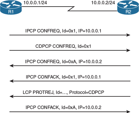
Figure 4-5 shows two routers negotiating the use of IPv4 and CDP over a PPP link. Both routers agree on using IPv4; however, CDP is suggested by R1 and is refused by R2 via an LCP Protocol-Reject (PROTREJ) message. The fact that a CDPCP CONFREJ message was responded to by an LCP PROTREJ message may be surprising at first. However, it is logical: Assuming that R2 does not support CDP, it also does not support the CDPCP, so it cannot respond using that particular NCP. Therefore, all NCP negotiations for unsupported protocols will be rejected by LCP PROTREJ messages. The Identifier values of these LCP PROTREJ messages do not correspond to the Identifier values of rejected NCP messages (they are numbered independently, so their numbering may overlap); instead, the Identifier value is simply a unique number increased for each PROTREJ message.
Advanced PPP Features
PPP supports a number of features not commonly seen with other protocols. We will have a brief look at three of them: compression, multilink, and PPPoE.
Compression
PPP supports both header and data payload compression. These features were most usable in the past when the WAN links were slow (tens or hundreds of Kbps) and when the bulk of data traffic contained uncompressed data. Nowadays, the compression mostly has lost its meaning: WAN links are faster by orders of magnitude, the bulk of data traffic is already compressed (think of graphics or video), and performing compression under these circumstances would strain the CPU on routers so much that it would become the new bottleneck. Nonetheless, it is always an advantage to at least have an overview of what is possible.
Header compression in PPP can be divided into several categories based on which header fields are to be compressed:
![]() Protocol Field Compression (PFC) allows shrinking the two-octet Protocol field to a one-octet value. This functionality is negotiated by LCP.
Protocol Field Compression (PFC) allows shrinking the two-octet Protocol field to a one-octet value. This functionality is negotiated by LCP.
![]() Address and Control Field Compression (ACFC) allows omitting the Address and Control fields from the HDLC frame because they carry a constant value all the time. This functionality is negotiated by LCP.
Address and Control Field Compression (ACFC) allows omitting the Address and Control fields from the HDLC frame because they carry a constant value all the time. This functionality is negotiated by LCP.
![]() Compression of IP+TCP and IP+UDP+RTP headers allows for the shrinking of these headers for a particular packet flow by an order of magnitude. This functionality is negotiated by IPCP.
Compression of IP+TCP and IP+UDP+RTP headers allows for the shrinking of these headers for a particular packet flow by an order of magnitude. This functionality is negotiated by IPCP.
Payload compression applies to the contents of the Information field indiscriminately. Cisco routers may support different compression mechanisms, such as LZS, MPPC, Predictor, and Stac. The use of payload compression is negotiated by a standalone NCP called the Compression Control Protocol (CCP).
Multilink PPP
Multilink PPP (MLPPP) is a unique feature that allows bundling multiple parallel links toward the same neighboring router and utilizing the aggregate bandwidth. This feature was originally designed to make efficient use of multiple B-channels on an ISDN interface, but it can be used to bundle any number of any point-to-point links running PPP between the same neighboring devices, even if the links are not of the same transmission speed.
As opposed to the well-known EtherChannel technology, where frames of a particular data flow are carried only by a single link in the bundle, MLPPP first creates a naked PPP frame by encapsulating each transmitted packet according to the usual PPP rules. It then splits this naked PPP frame into several fragments, adds a new HDLC+PPP+MLPPP header to each of these fragments, and sends them over the multiple links to the neighboring router. The MLPPP header contains a sequence number used to reassemble the fragments into the proper order, and two bits indicating that the particular fragment is either the first or the last fragment of the original naked PPP frame. This way, MLPPP allows even a single data flow to be split among multiple links and thus experience bandwidth improvement.
Multilink PPP is the underlying mechanism for the Link Fragmentation and Interleaving (LFI) QoS tool that allows interspersing short high-priority packets with fragments of longer lower-priority packets to reduce the jitter and queuing delay of high-priority flows.
PPP over Ethernet
PPPoE, which stands for PPP over Ethernet, is a technology originally developed to build PPP sessions between possibly multiple clients and an access concentrator, assuming that these clients and the access concentrator are interconnected by a common Ethernet network and are thus located in a single broadcast domain. This application was motivated by the fact that Ethernet has gradually grown into the role of a cost-effective, fast, and reasonably reliable network access technology. With Ethernet as an access technology, clients could connect to a service provider without needing to purchase any special devices or interfaces, using just their Ethernet network interfaces. At the same time, however, providers did not want to change their core networks and internal mechanisms, and if their client connectivity model was built on top of PPP, they wanted to keep PPP in place even if the access technology changed. Quite naturally, this called for some kind of integration of PPP and Ethernet.
PPPoE is the result of this integration. Defined in RFC 2516, PPPoE is basically a control and adaptation mechanism for PPP that allows carrying PPP frames across an Ethernet network between a client and an access concentrator. PPPoE also provides mechanisms for a client to dynamically discover an access concentrator and associate with it. With PPPoE, multiple clients, and even multiple PPP sessions from the same client, can be served by a single access concentrator within the same Ethernet network. Essentially, PPPoE defines the encapsulation procedure to carry PPP frames within Ethernet frames as well as the control procedures required for a client to discover, associate with, and disassociate with an access concentrator.
With regard to encapsulation, PPPoE defines a six-octet-long PPPoE header that is inserted together with each naked PPP frame into the Ethernet frame payload. Among other information, the most important field in the PPPoE header is the Session ID field. This is a unique number assigned to a particular client and that client’s PPP session by the access concentrator during the association procedure. This Session ID field allows the access concentrator to distinguish between different clients and their PPP sessions. Client MAC addresses alone are not used to differentiate between clients and individual PPP sessions because a single client can have multiple PPPoE clients and thus multiple PPP sessions running over the same interface. Because the naked PPP frame contains the Protocol field, which is two octets long, the total overhead of PPPoE is 6 + 2 = 8 bytes. This is the reason why on PPPoE virtual interfaces, the MTU is being decreased by a value of 8, to 1492, to provide sufficient space for the additional PPPoE+PPP headers.
PPPoE operates in two distinct stages—the Discovery Stage and the PPP Session Stage. The purpose of the Discovery Stage is to allow the client to discover an access concentrator and associate with it. The Discovery Stage strongly resembles a DHCP operation:
1. The client broadcasts a PPPoE Active Discovery Initiation (PADI) frame, soliciting access concentrators in the same broadcast domain.
2. Each access concentrator that receives the PADI responds by unicasting a PPPoE Active Discovery Offer (PADO) frame to the client.
3. After choosing one particular access concentrator, the client unicasts a PPPoE Active Discovery Request (PADR) frame to the chosen concentrator to associate with it.
4. If the access concentrator is willing to handle this client, it responds with a unicast PPPoE Active Discovery Session-confirmation (PADS) frame, assigning a unique Session ID to this particular client’s session.
After receiving the PADS frame, the client moves to the PPP Session Stage. This stage allows the clients to send and receive PPP frames using Ethernet+PPPoE encapsulation. In all outgoing Ethernet+PPPoE frames, the client must use the Session ID assigned by the access concentrator in the PADS message, and, conversely, all incoming Ethernet+PPPoE frames will have the same Session ID filled in by the access concentrator. During the PPP Session Stage, all PPP operations are entirely the same as if PPP were running over a serial link in HDLC framing.
The PPP Session Stage can be terminated by either the client or the access concentrator by sending a PPPoE Active Discovery Termination (PADT) message. Usually, though, this will be a result of PPP itself tearing down the PPP session beforehand using the LCP Terminate-Request and Terminate-Ack messages.
To better distinguish PPPoE control (discovery) frames from data (session) frames, all discovery frames have an EtherType of 0x8863, whereas all session frames have an EtherType of 0x8864.
Although PPPoE was not designed specifically with DSL in mind, DSL has reused PPPoE and is arguably the most extensively deployed access technology that internally relies on PPPoE.
Lab 4-1: PPP
Note Before proceeding with this lab, you need to copy and paste the running configuration information found in the Lab4-1_PPP.txt file. Once these configurations have been installed, you may proceed with Task 1.
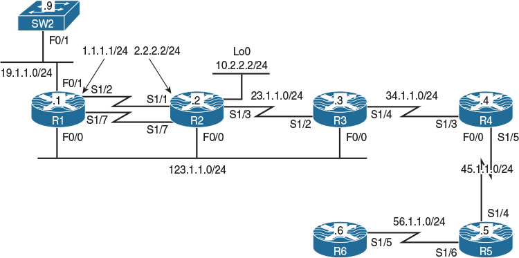
Figure 4-6 PPP and PPPoE Lab Topology
Task 1
Configure the S1/2 interface of R1 and the S1/1 interface of R2 so that they can ping each other. Do not configure an IGP, change their IP addresses, or use PBR, NAT, or any global configuration mode command to accomplish this task.
Figure 4-6 shows that the serial interfaces S1/2 on R1 and S1/1 on R2 facing each other are not configured in the same IP network. Without additional configuration, R1 won’t be able to reach R2, and vice versa, because neither of these two routers will consider the other to be on a directly connected network. Two manually configured static routes, one on each router, can fix this problem—but the task assignment explicitly prohibits using a global configuration mode command.
However, we are not prohibited from changing the encapsulation on the serial interfaces. If the encapsulation is changed to PPP, each router will automatically add a /32 route toward the other router’s IP address. This automatically added route to the neighbor’s IP address is also called a neighbor route, and adding it is a part of the IPCP operation. As a result, these routers will be able to ping each other as soon as the link comes up.
Let’s first change the serial link encapsulation on R1 and R2 to PPP:
! On R1:
R1(config)# interface serial1/2
R1(config-if)# encapsulation PPP
! On R2:
R2(config)# interface serial1/1
R2(config-if)# encapsulation PPP
To see the IPCP and add the neighbor route in action, let’s bring the S1/2 interface on R1 down, activate debug ppp negotiation, and then bring the S1/2 interface back up:
R1(config)# interface s1/2
R1(config-if)# shutdown
%LINK-5-CHANGED: Interface Serial1/2, changed state to administratively down
%LINEPROTO-5-UPDOWN: Line protocol on Interface Serial1/2, changed state to down
R1(config-if)# do debug ppp negotiation
PPP protocol negotiation debugging is on
R1(config-if)# no shutdown
%LINK-3-UPDOWN: Interface Serial1/2, changed state to up
Se1/2 PPP: Sending cstate UP notification
Se1/2 PPP: Processing CstateUp message
PPP: Alloc Context [49A53484]
ppp4 PPP: Phase is ESTABLISHING
Se1/2 PPP: Using default call direction
Se1/2 PPP: Treating connection as a dedicated line
Se1/2 PPP: Session handle[4B000004] Session id[4]
Se1/2 LCP: Event[OPEN] State[Initial to Starting]
Se1/2 LCP: O CONFREQ [Starting] id 1 len 10
Se1/2 LCP: MagicNumber 0x0718A653 (0x05060718A653)
Se1/2 LCP: Event[UP] State[Starting to REQsent]
Se1/2 LCP: I CONFREQ [REQsent] id 1 len 10
Se1/2 LCP: MagicNumber 0x1C631023 (0x05061C631023)
Se1/2 LCP: O CONFACK [REQsent] id 1 len 10
Se1/2 LCP: MagicNumber 0x1C631023 (0x05061C631023)
Se1/2 LCP: Event[Receive ConfReq+] State[REQsent to ACKsent]
Se1/2 LCP: I CONFACK [ACKsent] id 1 len 10
Se1/2 LCP: MagicNumber 0x0718A653 (0x05060718A653)
Se1/2 LCP: Event[Receive ConfAck] State[ACKsent to Open]
Se1/2 PPP: Queue IPCP code[1] id[1]
Se1/2 PPP: Phase is FORWARDING, Attempting Forward
Se1/2 LCP: State is Open
Se1/2 PPP: Phase is ESTABLISHING, Finish LCP
Se1/2 PPP: Phase is UP
Se1/2 IPCP: Protocol configured, start CP. state[Initial]
Se1/2 IPCP: Event[OPEN] State[Initial to Starting]
Se1/2 IPCP: O CONFREQ [Starting] id 1 len 10
Se1/2 IPCP: Address 1.1.1.1 (0x030601010101)
Se1/2 IPCP: Event[UP] State[Starting to REQsent]
Se1/2 PPP: Process pending ncp packets
Se1/2 IPCP: Redirect packet to Se1/2
Se1/2 IPCP: I CONFREQ [REQsent] id 1 len 10
Se1/2 IPCP: Address 2.2.2.2 (0x030602020202)
Se1/2 IPCP: O CONFACK [REQsent] id 1 len 10
Se1/2 IPCP: Address 2.2.2.2 (0x030602020202)
Se1/2 IPCP: Event[Receive ConfReq+] State[REQsent to ACKsent]
%LINEPROTO-5-UPDOWN: Line protocol on Interface Serial1/2, changed state to up
Se1/2 IPCP: I CONFACK [ACKsent] id 1 len 10
Se1/2 IPCP: Address 1.1.1.1 (0x030601010101)
Se1/2 IPCP: Event[Receive ConfAck] State[ACKsent to Open]
Se1/2 IPCP: State is Open
Se1/2 Added to neighbor route AVL tree: topoid 0, address 2.2.2.2
Se1/2 IPCP: Install route to 2.2.2.2
In the preceding transcript, the codes I and O, shown with various LCP and NCP protocol messages, stand for Incoming and Outgoing, respectively.
The neighbor routes can now be seen in the routing tables on both routers, and we can check whether R1 and R2 can reach each other, like so:
! On R1:
R1# show ip route | begin Gate
Gateway of last resort is not set
1.0.0.0/8 is variably subnetted, 2 subnets, 2 masks
C 1.1.1.0/24 is directly connected, Serial1/2
L 1.1.1.1/32 is directly connected, Serial1/2
2.0.0.0/32 is subnetted, 1 subnets
C 2.2.2.2 is directly connected, Serial1/2
19.0.0.0/8 is variably subnetted, 2 subnets, 2 masks
C 19.1.1.0/24 is directly connected, FastEthernet0/1
L 19.1.1.1/32 is directly connected, FastEthernet0/1
! On R2:
R2# show ip route | begin Gate
Gateway of last resort is not set
1.0.0.0/32 is subnetted, 1 subnets
C 1.1.1.1 is directly connected, Serial1/1
2.0.0.0/8 is variably subnetted, 2 subnets, 2 masks
C 2.2.2.0/24 is directly connected, Serial1/1
L 2.2.2.2/32 is directly connected, Serial1/1
10.0.0.0/8 is variably subnetted, 2 subnets, 2 masks
C 10.2.2.0/24 is directly connected, Loopback0
L 10.2.2.2/32 is directly connected, Loopback0
! On R1:
R1# ping 2.2.2.2
Type escape sequence to abort.
Sending 5, 100-byte ICMP Echos to 2.2.2.2, timeout is 2 seconds:
!!!!!
Success rate is 100 percent (5/5), round-trip min/avg/max = 28/29/32 ms
R1# undebug all
All possible debugging has been turned off
The adding of a neighbor route to a particular neighbor can also be disabled on a router by configuring the no peer neighbor-route command on its serial interface toward this neighbor, although this is seldom necessary.
! On R1:
R1# show ppp all
Interface/ID OPEN+ Nego* Fail- Stage Peer Address Peer Name
------------ --------------------- -------- --------------- --------------------
Se1/1 LCP+ IPCP+ CDPCP+ LocalT 2.2.2.2
As you can see, the Network Control Protocols LCP, IPCP, and CDPCP have been successfully negotiated and are functioning properly because they are in the OPEN state.
Task 2
Configure R1 so that it can ping R2’s loopback0 interface. Do not configure a static route, any routing protocol, NAT, or PBR to accomplish this task.
Let’s see if R1 can ping the loopback0 interface of R2 already:
R1# ping 10.2.2.2
Type escape sequence to abort.
Sending 5, 100-byte ICMP Echos to 10.2.2.2, timeout is 2 seconds:
.....
Success rate is 0 percent (0/5)
Obviously, it cannot, because it does not know the route to this address. This problem can be solved by instructing IPCP to inject a default route on R1 pointing toward R2. Let’s configure this feature first:
R1(config)# interface serial1/2
R1(config-if)# ppp ipcp route default
R1(config-if)# shutdown
%LINK-5-CHANGED: Interface Serial1/2, changed state to administratively down
%LINEPROTO-5-UPDOWN: Line protocol on Interface Serial1/2, changed state to down
R1(config-if)# no shutdown
Now let’s verify it:
R1# show ip route | begin Gate
Gateway of last resort is 2.2.2.2 to network 0.0.0.0
S* 0.0.0.0/0 [1/0] via 2.2.2.2
1.0.0.0/8 is variably subnetted, 2 subnets, 2 masks
C 1.1.1.0/24 is directly connected, Serial1/2
L 1.1.1.1/32 is directly connected, Serial1/2
2.0.0.0/32 is subnetted, 1 subnets
C 2.2.2.2 is directly connected, Serial1/2
19.0.0.0/8 is variably subnetted, 2 subnets, 2 masks
C 19.1.1.0/24 is directly connected, FastEthernet0/1
L 19.1.1.1/32 is directly connected, FastEthernet0/1
R1# ping 10.2.2.2
Type escape sequence to abort.
Sending 5, 100-byte ICMP Echos to 10.2.2.2, timeout is 2 seconds:
!!!!!
Success rate is 100 percent (5/5), round-trip min/avg/max = 28/29/32 ms
Note If the no peer neighbor-route command is configured on the interface toward a neighbor, the default route through this neighbor will not be injected, either.
Task 3
Configure R2 so that it can assign an IP address of 23.1.1.3 to R3’s s1/2 interface. Do not configure DHCP to accomplish this task.
One of the benefits of PPP encapsulation is the ability to assign an IP address to a directly connected neighboring host using IPCP.
The following commands must be configured on these two routers:
1. PPP encapsulation must be configured on the serial interfaces of these two routers that face each other.
2. On R2, the peer default ip address 23.1.1.3 interface command instructs the router to assign the IP address of 23.1.1.3 to R3.
3. On R3, the ip address negotiated interface command must be configured.
Let’s configure these commands, then:
! On R2:
R2(config)# interface serial1/3
R2(config-if)# encapsulation ppp
R2(config-if)# shutdown
%LINK-5-CHANGED: Interface Serial1/3, changed state to administratively down
%LINEPROTO-5-UPDOWN: Line protocol on Interface Serial1/3, changed state to down
R2(config-if)# peer default ip address 23.1.1.3
R2(config-if)# no shutdown
! On R3:
R3(config)# interface serial1/2
R3(config-if)# encapsulation ppp
R3(config-if)# ip address negotiated
R3(config-if)# no shutdown
Now let’s verify and test the configuration:
R3# show ip interface brief serial1/2
Interface IP-Address OK? Method Status Protocol
Serial1/2 23.1.1.3 YES IPCP up up
R3# ping 23.1.1.2
Type escape sequence to abort.
Sending 5, 100-byte ICMP Echos to 23.1.1.2, timeout is 2 seconds:
!!!!!
Success rate is 100 percent (5/5), round-trip min/avg/max = 28/29/32 ms
Task 4
Configure one-way PAP authentication between the serial interfaces of R3 and R4. R3 should be configured to authenticate R4 (that is, R4 must prove its identity, or authenticate itself, to R3) using PAP. R4 should use “R4” as its username and “Cisco” as its password.
Among the authentication mechanisms supported by PPP are PAP and CHAP. These authentication methods are defined in RFCs 1334 and 1994, respectively. PAP, in particular, provides a simple though unsecure method for authentication. In PAP, the password is sent across the link in cleartext, and there is no protection from playback or trial-and-error attacks. Nor is there a possibility of periodic reauthentication between PPP peers.
To better illustrate how PAP works, consider the following two figures of PAP messages dissected by the Wireshark traffic analyzer. Figure 4-7 shows a PAP AUTH-REQ message from R4 to R3, plainly carrying the sensitive data.
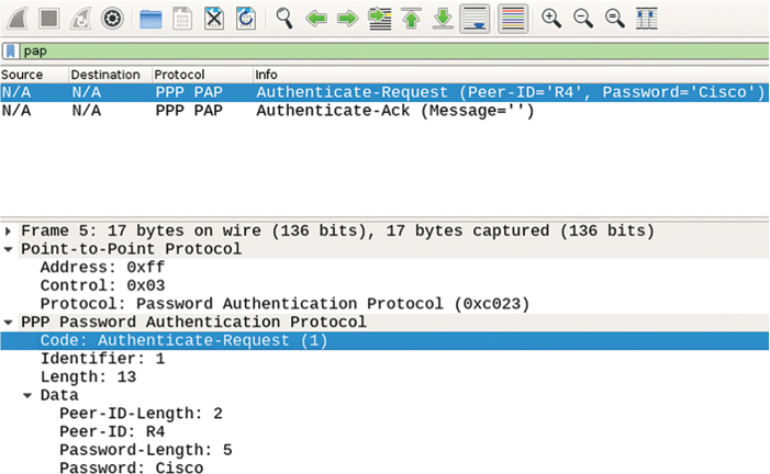
Figure 4-7 PAP AUTH-REQ Message
In Figure 4-7, notice that the PAP message is actually a PPP frame’s payload with a Protocol identifier of 0xc023. The PAP message contains the following information: Code identifies the actual PAP message, Identifier is a value used to pair together requests and responses, Length describes the length of the entire PAP message, and the Data portion contains the actual credentials.
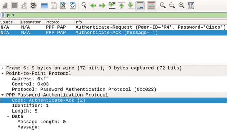
Figure 4-8 shows a PAP AUTH-ACK message confirming a successful authentication. This message has an empty Data portion because it does not carry any additional information. If this message was a PPP AUTH-NAK message, the Message field in the Data portion would contain an optional error message clarifying why the authentication failed.
According to the task, R3 is the router that will verify the identity of R4 using PAP, while R4 needs to provide information over PAP that proves that it is what it claims to be. R3 must therefore be configured to ask R4 to provide authentication information, while R4 must be configured with a proper username and password combination to be sent to R3 when it asks for it.
Let’s start with the configuration of R3 and enable debug ppp authentication along the way, as we configure the task.
R3(config)# do debug ppp authentication
PPP authentication debugging is on
R3(config)# interface serial1/4
R3(config-if)# encapsulation ppp
R3(config-if)# ppp authentication pap
The ppp authentication pap command configures R3 to be the authenticator, which requests that the connected peer authenticate itself using PAP. This command instructs R3 to inform R4 during the initial LCP exchange phase that it wants R4 to prove its identity using PAP. Note that the particular authentication method is always negotiated in the LCP phase before the authentication exchange itself.
Next, configure R4 with the username and password combination that should be sent to whoever requests this information over PAP:
R4(config)# interface serial1/3
R4(config-if)# encapsulation ppp
R4(config-if)# ppp pap sent-username R4 password Cisco
The ppp pap sent-username command configures R4 to send the indicated username and password in a PAP AUTH-REQ (Authentication Request) message to R3.
After this is configured, R3 displays a set of debugging messages similar to the following output:
! On R3:
Se1/4 PPP: Using default call direction
Se1/4 PPP: Treating connection as a dedicated line
Se1/4 PPP: Session handle[2C000073] Session id[115]
Se1/4 PAP: I AUTH-REQ id 1 len 13 from "R4"
Se1/4 PAP: Authenticating peer R4
Se1/4 PPP: Sent PAP LOGIN Request
Se1/4 PPP: Received LOGIN Response FAIL
Se1/4 PAP: O AUTH-NAK id 1 len 26 msg is "Authentication failed"
The output of the preceding debug reveals that R3 received R4’s username and password but it sent an AUTH-NAK (Negative Acknowledgment) back to R4, telling it that the authentication failed. This is because R3 checked the received credentials against its user account database and did not find a matching entry.
Here’s how to see the number of failed attempts:
R3# show ppp statistics | include Counter|PAP
Type PPP MIB Counters PEAK CURRENT
51 PAP authentication attempts 10 10
52 PAP authentication successes 0 0
53 PAP authentication failures 10 10
54 User failed PAP authentication 10 10
Let’s add the username and password for R4 to R3’s user account database:
! On R3:
R3(config)# username R4 password Cisco
Se1/4 PPP: Using default call direction
Se1/4 PPP: Treating connection as a dedicated line
Se1/4 PPP: Session handle[D400000F] Session id[270]
Se1/4 PAP: I AUTH-REQ id 1 len 13 from "R4"
Se1/4 PAP: Authenticating peer R4
Se1/4 PPP: Sent PAP LOGIN Request
Se1/4 PPP: Received LOGIN Response PASS
Se1/4 PAP: O AUTH-ACK id 1 len 5
This time, R3 responds with an AUTH-ACK message, indicating to R4 that the authentication is successful.
Now let’s test the configuration:
R3# ping 34.1.1.4
Type escape sequence to abort.
Sending 5, 100-byte ICMP Echos to 34.1.1.4, timeout is 2 seconds:
!!!!!
Success rate is 100 percent (5/5), round-trip min/avg/max = 28/29/32 ms
R3# undebug all
All possible debugging has been turned off
Task 5
Configure two-way PAP authentication between the serial interfaces of R4 and R5 using the following parameters:
![]() R4: Username R4, password R4
R4: Username R4, password R4
![]() R5: Username R5, password R5
R5: Username R5, password R5
Because R4 uses a username of R4 and a password of R4, this username and password must be configured on R5, and the username and the password that is used by R5 should be configured on R4, as shown here:
! On R4:
R4(config)# username R5 password R5
! On R5:
R5(config)# username R4 password R4
PPP encapsulation must be configured on the serial interfaces of these two routers that face each other:
! On R4:
R4(config)# interface serial1/5
R4(config-if)# encapsulation ppp
! On R5:
R5(config)# interface serial1/4
R5(config-if)# encapsulation ppp
Configure the username and the password on the serial interfaces of these two routers:
! On R4:
R4(config)# interface serial1/5
R4(config-if)# ppp pap sent-username R4 password R4
! On R5:
R5(config)# interface serial1/4
R5(config-if)# ppp pap sent-username R5 password R5
The final step is to configure both routers as authenticators to mutually request authentication from each other:
! On R4:
R4(config)# interface serial1/5
R4(config-if)# ppp authentication pap
! On R5:
R5(config)# interface serial1/4
R5(config-if)# ppp authentication pap
To see and verify the two-way authentication, let’s bring down the s1/5 interface of R4, enable debug ppp authentication, and then activate the s1/5 interface on R4 again:
R4(config)# interface serial1/5
R4(config-if)# shutdown
R4(config-if)# do debug ppp authentication
PPP authentication debugging is on
R4(config-if)# no shutdown
Se1/5 PPP: Using default call direction
Se1/5 PPP: Treating connection as a dedicated line
Se1/5 PPP: Session handle[90000014] Session id[276]
Se1/5 PAP: Using hostname from interface PAP
Se1/5 PAP: Using password from interface PAP
Se1/5 PAP: O AUTH-REQ id 1 len 10 from "R4"
Se1/5 PAP: I AUTH-REQ id 1 len 10 from "R5"
Se1/5 PAP: Authenticating peer R5
Se1/5 PPP: Sent PAP LOGIN Request
Se1/5 PPP: Received LOGIN Response PASS
Se1/5 PAP: O AUTH-ACK id 1 len 5
Se1/5 PAP: I AUTH-ACK id 1 len 5
The output shows R4 both sending and receiving an AUTH-REQ message, and subsequently both sending and receiving an AUTH-ACK message, suggesting that both R4 and R5 have mutually authenticated themselves successfully.
Another way to verify whether PAP was successful is with the show ppp all command, shown here:
R4# show ppp all
Interface/ID OPEN+ Nego* Fail- Stage Peer Address Peer Name
------------ --------------------- -------- --------------- --------------------
Se1/5 LCP+ PAP+ IPCP+ CDPC> LocalT 45.1.1.5 R5
Se1/3 LCP+ IPCP+ CDPCP+ LocalT 34.1.1.3
In the output, CDPC> simply means that the field has been truncated. Use the show ppp interface command to view the full output:
R4# show ppp interface serial1/5
PPP Serial Context Info
-------------------
Interface : Se1/5
PPP Serial Handle: 0x9700002B
PPP Handle : 0xDD00002B
SSS Handle : 0xA300002B
Access IE : 0xB000029
SHDB Handle : 0x0
State : Up
Last State : Binding
Last Event : LocalTerm
PPP Session Info
----------------
Interface : Se1/5
PPP ID : 0xDD00002B
Phase : UP
Stage : Local Termination
Peer Name : R5
Peer Address : 45.1.1.5
Control Protocols: LCP[Open] PAP+ IPCP[Open] CDPCP[Open]
Session ID : 41
AAA Unique ID : 55
SSS Manager ID : 0xA300002B
SIP ID : 0x9700002B
PPP_IN_USE : 0x11
Se1/5 LCP: [Open]
Our Negotiated Options
Se1/5 LCP: AuthProto PAP (0x0304C023)
Se1/5 LCP: MagicNumber 0xBCC153A3 (0x0506BCC153A3)
Peer's Negotiated Options
Se1/5 LCP: AuthProto PAP (0x0304C023)
Se1/5 LCP: MagicNumber 0xBCC152D1 (0x0506BCC152D1)
Se1/5 IPCP: [Open]
Our Negotiated Options
Se1/5 IPCP: Address 45.1.1.4 (0x03062D010104)
Peer's Negotiated Options
Se1/5 IPCP: Address 45.1.1.5 (0x03062D010105)
Se1/5 CDPCP: [Open]
Our Negotiated Options
NONE
Peer's Negotiated Options
NONE
PAP authentication is shown as an LCP “negotiated option.”
Task 6
Configure one-way CHAP authentication between the serial interfaces of R5 and R6. R5 should be configured to send a challenge to R6. Use the following parameters to accomplish this task:
![]() R5: Username R5, password aaa
R5: Username R5, password aaa
![]() R6: Username R6, password aaa
R6: Username R6, password aaa
The Challenge Handshake Authentication Protocol, or CHAP, is defined in RFC 1994. CHAP can be used to verify the identity of the peer by exchanging three packets: a Challenge packet, a Response packet, and a Success or Failure indication.
CHAP can be used in one-way or two-way authentication. In this task, we will configure CHAP in a one-way authentication manner. As for the authentication direction, R5 is the authenticator because the task states that R5 should send a challenge to R6, and a challenge is always sent out from the router that asks its peer to prove its identity. This means that R5 will be configured with the ppp authentication chap interface command and a username/password combination that matches the credentials configured on R6, whereas R6 will be configured with the credentials necessary to authenticate to R5.
To better understand the processes behind CHAP, we will have a look at the contents of CHAP messages as dissected by Wireshark.
R5 as an authenticator begins the CHAP authentication process by sending a CHAP Challenge packet to R6. Figure 4-9 shows the contents of the CHAP Challenge packet.
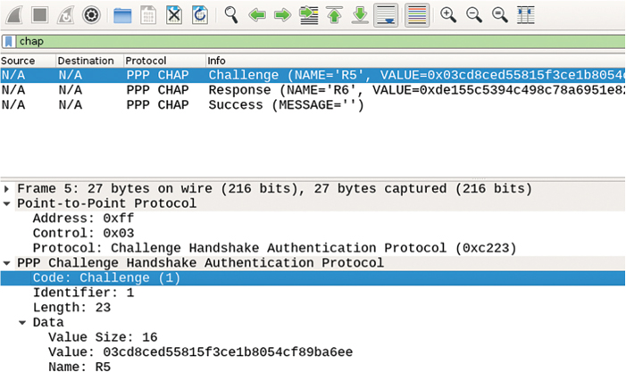
Figure 4-9 CHAP Challenge Packet Contents
The Protocol field in the PPP frame header identifies CHAP with its protocol number 0xc223. A CHAP Challenge packet contains the Code field identifying the particular CHAP message type, an Identifier value that is used to pair this message with the Response packet from the peer, a Length field covering the length of the entire CHAP message, and the Data portion. The Data portion itself consists of the challenge size (Value Size), the challenge itself (Value), and the hostname of the sender that originates the challenge (Name).
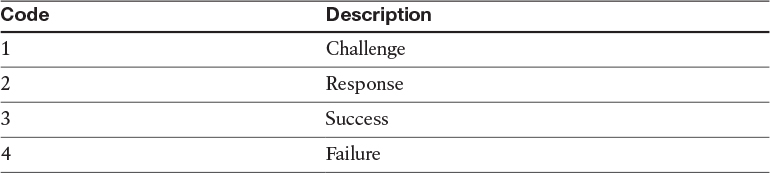
The Code field can carry one of the four possible values shown in Table 4-1.
Table 4-1 CHAP Message Types
The Value field is the actual challenge originated by R5 and is sent to R6 for processing. Whenever R5 originates a new challenge, this field carries a new pseudorandom (ideally, a random) value that cannot be predicted.
The Name field, by default, carries the hostname of the router sending the challenge, but it can be changed using the ppp chap hostname interface configuration mode command.
After R6 receives the Challenge packet, it tries to look up the name indicated in the Name field of the Challenge packet in its local user account database. If it finds a matching entry, it feeds the password associated with that username into an MD5 hash generator, along with the contents of the Identifier and Value fields from the Challenge packet (the precise order of data fed into the MD5 sum is the Identifier field, then the password, then the Value field). The result of this MD5 hash is the response that needs to be sent back to R5.
R6 therefore builds a CHAP Response packet and sends it to R5. The contents of a CHAP Response packet are shown in Figure 4-10.
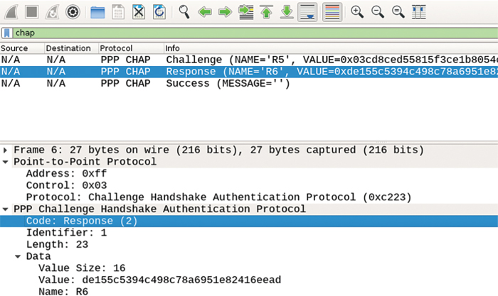
Note that the format of a CHAP Response packet is very similar to the CHAP Challenge packet. The Code value is set to 2, indicating a Response packet. Identifier is set to 1, identical to the preceding Challenge, allowing R5 to match its former Challenge with this Response. The Length field again indicates the length of the entire CHAP message, and the Data portion contains the length of the response itself (Value Size), the MD5 value comprising the response (Value), and again the hostname of the sending host (Name).
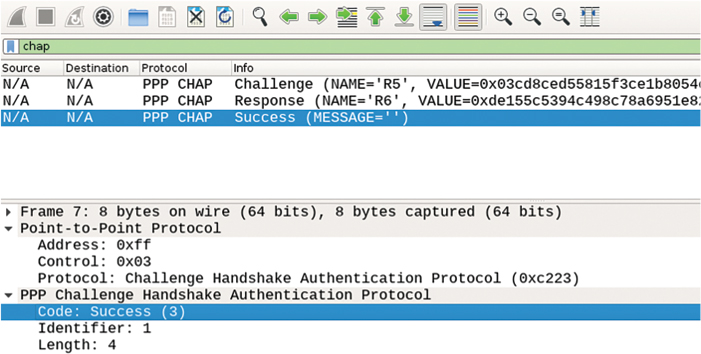
R5 receives this Response message from R6. Using the Name field contents from the Response message, it looks up the matching username in its user account database. R5 then uses the password associated with the matching username together with the Identifier field and the original challenge value to compute its own MD5 hash result and then compares it to the Value field in the received Response packet. If they match, it is clear that R6 knows the same password as R5, that R6 is responding to the same challenge R5 sent it in the first step, and that the Challenge and Response packets’ fields processed by the MD5 hash have not been tampered with while in transit. R5 can now claim that R6 is authentic and send a CHAP Success message, as shown in Figure 4-11. If, however, the computed MD5 hash does not match the Value field in the received Response packet, R5 will send back a Failure packet.
When you’re configuring CHAP authentication, it is useful to follow the path of actual CHAP messages and configure routers in that sequence to minimize configuration errors.
Let’s now configure one-way CHAP authentication on R5 and R6. We start by configuring R5 to start the authentication process and send a Challenge packet to R6:
R5(config)# interface serial1/6
R5(config-if)# encapsulation ppp
R5(config-if)# ppp authentication chap
On R6, PPP needs to be configured:
R6(config)# interface serial1/5
R6(config-if)# encapsulation ppp
Because R5 includes its own hostname in the Name field of the Challenge packet, and R6 will perform a lookup in its user account database for the associated password to be used with R5, R6 has to be configured with a username and a password for R5:
R6(config)# username R5 password aaa
With the preceding command configured, R6 can find the password for R5 and use it in computing its Response message contents, but R6 will also include its hostname in the Response packet, so R5 has to find the proper password to validate R6’s response. Therefore, R5 must be configured with a username and password for R6, like so:
R5(config)# username R6 password aaa
To verify the configuration, bring the interface s1/6 on R5 down, enable debug ppp authentication, and reactivate the interface:
R5(config)# interface serial1/6
R5(config-if)# shutdown
R5(config-if)# do debug ppp authentication
PPP authentication debugging is on
R5(config-if)# no shutdown
Se1/6 PPP: Using default call direction
Se1/6 PPP: Treating connection as a dedicated line
Se1/6 PPP: Session handle[58000028] Session id[38]
Se1/6 CHAP: O CHALLENGE id 1 len 23 from "R5"
Se1/6 PPP: Sent CHAP SENDAUTH Request
Se1/6 PPP: Received SENDAUTH Response PASS
Se1/6 CHAP: Using hostname from configured hostname
Se1/6 CHAP: Using password from AAA
Se1/6 CHAP: I RESPONSE id 1 len 23 from "R6"
Se1/6 PPP: Sent CHAP LOGIN Request
Se1/6 PPP: Received LOGIN Response PASS
Se1/6 CHAP: O SUCCESS id 1 len 4
Finally, let’s test and verify the configuration:
R5# ping 56.1.1.6
Type escape sequence to abort.
Sending 5, 100-byte ICMP Echos to 56.1.1.6, timeout is 2 seconds:
!!!!!
Success rate is 100 percent (5/5), round-trip min/avg/max = 28/29/32 ms
msR5# show ppp all
Interface/ID OPEN+ Nego* Fail- Stage Peer Address Peer Name
------------ --------------------- -------- --------------- --------------------
Se1/6 LCP+ CHAP+ IPCP+ CDP> LocalT 56.1.1.6 R6
Se1/4 LCP+ PAP+ IPCP+ CDPC> LocalT 45.1.1.4 R4
Task 7
Reconfigure R5 and R6 to perform two-way CHAP authentication using the credentials from the previous task.
To configure this task, we have to configure R6 to also send a Challenge packet. This takes one additional command to accomplish. R5 will automatically respond with a proper Response packet because it has the necessary credentials for R6 already configured.
R6(config)# interface serial1/5
R6(config-if)# ppp authentication chap
To verify the configuration, bring the interface s1/5 on R6 down, enable debug ppp authentication, and reactivate the interface:
R6(config)# interface serial1/5
R6(config-if)# shutdown
R6(config-if)# do debug ppp authentication
PPP authentication debugging is on
R6(config-if)# no shutdown
Se1/5 PPP: Using default call direction
Se1/5 PPP: Treating connection as a dedicated line
Se1/5 PPP: Session handle[15000022] Session id[32]
Se1/5 CHAP: O CHALLENGE id 1 len 23 from "R6"
Se1/5 CHAP: I CHALLENGE id 1 len 23 from "R5"
Se1/5 PPP: Sent CHAP SENDAUTH Request
Se1/5 PPP: Received SENDAUTH Response PASS
Se1/5 CHAP: Using hostname from configured hostname
Se1/5 CHAP: Using password from AAA
Se1/5 CHAP: O RESPONSE id 1 len 23 from "R6"
Se1/5 CHAP: I RESPONSE id 1 len 23 from "R5"
Se1/5 PPP: Sent CHAP LOGIN Request
Se1/5 PPP: Received LOGIN Response PASS
Se1/5 CHAP: O SUCCESS id 1 len 4
Se1/5 CHAP: I SUCCESS id 1 len 4
Finally, let’s test the connectivity:
R6# ping 56.1.1.5
Type escape sequence to abort.
Sending 5, 100-byte ICMP Echos to 56.1.1.5, timeout is 2 seconds:
!!!!!
Success rate is 100 percent (5/5), round-trip min/avg/max = 28/29/32 ms
Task 8
In Task 4, R3 is configured to authenticate R4 (that is, verify R4’s identity) using PAP. Configure R4 to authenticate R3 (that is, verify R3’s identity) using CHAP. If this task is configured properly, R3 will authenticate R4 using PAP, and R4 will authenticate R3 using CHAP. Use the following parameters to accomplish the task:
![]() R3 username: R3
R3 username: R3
![]() R4 username: router4
R4 username: router4
![]() Shared secret: aaa
Shared secret: aaa
Before we start configuring the routers, we need to analyze the existing configuration on R3 and R4 to properly integrate it with the required changes for this task.
In Task 4, R4 sends a username/password combination of “R4/Cisco” to R3 via PAP to prove its identity. R3 therefore already has a username R4 password Cisco command present in its configuration. This task requires that R3 prove its own identity to R4 using a different password. An important observation is that R4 is required to use a different username when sending its Challenge packet to R3—“router4” instead of “R4”. Therefore, the existing R4’s account on R3 used by PAP is not affected; just a new username/password combination needs to be added to R3 so that when challenged by “router4”, it responds using the password “aaa”.
According to the task assignment, R4 is the CHAP authenticator and therefore must start the CHAP authentication exchange by sending a CHAP Challenge packet to R3. This is accomplished by configuring ppp authentication chap on R4’s interface toward R3. However, the assignment also requires that R4 use a username different from its preconfigured hostname. Therefore, R4’s interface toward R3 must also be configured with the required username using the ppp chap hostname command.
Let’s start first with R4, which is supposed to send a CHAP Challenge packet to R3 with a nondefault hostname:
R4(config)# interface serial1/3
R4(config-if)# ppp authentication chap
R4(config-if)# ppp chap hostname router4
On R3, as the node being authenticated, all that is necessary is to configure a username account for “router4” and a password of “aaa” so that this password is used to construct a Response packet back to “router4” (which is really R4):
R3(config)# username router4 password aaa
Finally, on R4 as an authenticator, we need to add R3’s account:
R4(config)# username R3 password aaa
To verify the configuration, let’s bring down the s1/3 interface of R4, enable debug ppp authentication, and then activate the s1/3 interface on R4 again:
R4(config)# interface serial1/3
R4(config-if)# shutdown
R4(config-if)# do debug ppp authentication
PPP authentication debugging is on
R4(config-if)# no shutdown
Se1/3 PPP: Using default call direction
Se1/3 PPP: Treating connection as a dedicated line
Se1/3 PPP: Session handle[E900009E] Session id[668]
Se1/3 PAP: Using hostname from interface PAP
Se1/3 PAP: Using password from interface PAP
Se1/3 PAP: O AUTH-REQ id 1 len 13 from "R4"
Se1/3 CHAP: O CHALLENGE id 1 len 28 from "router4"
Se1/3 CHAP: I RESPONSE id 1 len 23 from "R3"
Se1/3 PPP: Sent CHAP LOGIN Request
Se1/3 PAP: I AUTH-ACK id 1 len 5
Se1/3 PPP: Received LOGIN Response PASS
Se1/3 CHAP: O SUCCESS id 1 len 4
Now let’s test the configuration:
R4# ping 34.1.1.3
Type escape sequence to abort.
Sending 5, 100-byte ICMP Echos to 34.1.1.3, timeout is 2 seconds:
!!!!!
Success rate is 100 percent (5/5), round-trip min/avg/max = 28/33/48 ms
Here’s how to verify the configuration:
R4# show ppp interface serial1/3
PPP Serial Context Info
-------------------
Interface : Se1/3
PPP Serial Handle: 0xB3000001
PPP Handle : 0xB9000101
SSS Handle : 0x16000101
AAA ID : 269
Access IE : 0xC50000FD
SHDB Handle : 0x0
State : Up
Last State : Binding
Last Event : LocalTerm
PPP Session Info
----------------
Interface : Se1/3
PPP ID : 0xB9000101
Phase : UP
Stage : Local Termination
Peer Name : R3
Peer Address : 34.1.1.3
Control Protocols: LCP[Open] CHAP+ IPCP[Open] CDPCP[Open]
Session ID : 253
AAA Unique ID : 269
SSS Manager ID : 0x16000101
SIP ID : 0xB3000001
PPP_IN_USE : 0x11
Se1/3 LCP: [Open]
Our Negotiated Options
Se1/3 LCP: AuthProto CHAP (0x0305C22305)
Se1/3 LCP: MagicNumber 0xBD251DF0 (0x0506BD251DF0)
Peer's Negotiated Options
Se1/3 LCP: AuthProto PAP (0x0304C023)
Se1/3 LCP: MagicNumber 0xBD251B84 (0x0506BD251B84)
Se1/3 IPCP: [Open]
Our Negotiated Options
Se1/3 IPCP: Address 34.1.1.4 (0x030622010104)
Peer's Negotiated Options
Se1/3 IPCP: Address 34.1.1.3 (0x030622010103)
Se1/3 CDPCP: [Open]
Our Negotiated Options
NONE
Peer's Negotiated Options
NONE
As you can see, our LCP negotiated option is CHAP. Our peer’s LCP negotiated option is PAP.
Task 9
Configure PPPoE based on the following parameters:
![]() R1 should be configured as a PPPoE access concentrator. R2 and R3 should be configured as PPPoE clients.
R1 should be configured as a PPPoE access concentrator. R2 and R3 should be configured as PPPoE clients.
![]() R1 should be configured with an IP address of 123.1.1.1/24, and R2 and R3 should be configured to acquire an IP address from R1. R1 should be configured with a range that includes 123.1.1.2 and 123.1.1.3 IP addresses. Do not configure a DHCP to accomplish this task.
R1 should be configured with an IP address of 123.1.1.1/24, and R2 and R3 should be configured to acquire an IP address from R1. R1 should be configured with a range that includes 123.1.1.2 and 123.1.1.3 IP addresses. Do not configure a DHCP to accomplish this task.
![]() You should use the f0/0 interfaces of these routers to accomplish this task.
You should use the f0/0 interfaces of these routers to accomplish this task.
![]() Assign a MAC address of 0000.1111.1111, 0000.2222.2222, and 0000.3333.3333 to R1, R2 and R3, respectively.
Assign a MAC address of 0000.1111.1111, 0000.2222.2222, and 0000.3333.3333 to R1, R2 and R3, respectively.
With PPPoE, one device is configured as a PPPoE access concentrator that terminates PPPoE sessions from clients. For brevity purposes, we will call this device a “server,” although this is not the official terminology. Devices connecting to and establishing a PPPoE session with a PPPoE server are called “PPPoE clients.” In this task, R1 should be configured as the server, and R2 and R3 as the clients.
A Cisco IOS-based router can run multiple PPPoE server instances. Each PPPoE server instance is represented in the router configuration by a construct called the bba-group (Broad Band Aggregation). A bba-group holds the configuration details of a particular PPPoE server instance, such as the access concentrator name presented to clients, the maximum number of attached clients, and, most importantly, a reference to a specific Virtual-Template interface. A Virtual-Template interface is a placeholder for the configuration of per-client Virtual-Access interfaces that are created on the fly, one for each connected PPPoE client. Whenever a new PPPoE client connects to a PPPoE server, the server dynamically creates a new Virtual-Access interface for this client that inherits the complete configuration from the Virtual-Template interface. In other words, Virtual-Access interfaces are instances of the Virtual-Template interface, instantiated at the moment of accepting a PPPoE client, and destroyed when the client disconnects. Virtual-Template interfaces are commonly configured with all the configuration that applies to all clients, such as PPP authentication, MTU, TCP MSS manipulation, NAT, ACLs, and so on. The entire bba-group is applied to a physical Ethernet interface or subinterface to make the router listen for PPPoE clients on that particular interface or VLAN.
Let’s configure the PPPoE server on R1. In the following configuration snippet, we first configure a loopback interface with an IP address that will subsequently be shared with the Virtual-Template interface, and consequently with all Virtual-Access interfaces cloned off the Virtual-Template. Although the Virtual-Template interface can be configured with an IP address directly, it is customary to use IP Unnumbered with Virtual-Template interfaces. This also saves us from a series of harmless-yet-annoying console messages about overlapping IP networks that would otherwise appear when Virtual-Access interfaces are instantiated. Next, we create a Virtual-Template interface, assign it an IP address, and have all clients handled by Virtual-Access instances of this interface be offered IP addresses from the local address pool named “tst-pool”. We do not configure a DHCP pool because this was prohibited in the task assignment. In addition, because PPPoE encapsulation causes 8 bytes from each frame to be consumed by PPPoE and PPP headers while the maximum payload of an Ethernet frame remains fixed at 1500 bytes, we need to decrease the available MTU for the interface by 8 bytes. All IP packets larger than 1492 bytes will therefore need to be fragmented by the router; otherwise, after PPPoE and PPP headers are added, their size would exceed 1500 bytes and they would not fit into Ethernet frames. Specifically for TCP, we configure the router to silently modify the Maximum Segment Size (MSS) value in all TCP SYN and SYN+ACK segments to take into account the 40-byte TCP header so that it does not exceed the value of 1452. Thanks to this, TCP sessions carried by PPPoE will never encounter segments larger than 1452 bytes in payload; therefore, their total size including TCP and IP headers will not exceed 1492 bytes, thus avoiding the need to be fragmented. Finally, we configure the “tst-pool” pool with the desired addresses for PPPoE clients. Note that we do not configure encapsulation ppp on the Virtual-Template interface because that is the default encapsulation.
R1(config)# interface loopback123
R1(config-if)# ip address 123.1.1.1 255.255.255.0
R1(config-if)# exit
R1(config)# interface virtual-template123
R1(config-if)# ip unnumbered loopback123
R1(config-if)# peer default ip address pool tst-pool
R1(config-if)# mtu 1492
R1(config-if)# ip tcp adjust-mss 1452
R1(config-if)# exit
R1(config)# ip local pool tst-pool 123.1.1.2 123.1.1.3
Next, we create a PPPoE server instance and refer it to the Virtual-Template interface created earlier:
R1(config)# bba-group pppoe tst
R1(config-bba-group)# virtual-template 123
Finally, we attach this PPPoE server instance to the f0/0 interface, along with changing its MAC address:
R1(config)# interface fastethernet0/0
R1(config-if)# mac-address 0000.1111.1111
R1(config-if)# pppoe enable group tst
R1(config-if)# no shutdown
PPPoE clients are configured using yet another type of virtual interface: a Dialer interface. This interface type is commonly used for dialed connections over analog and ISDN BRI or PRI interfaces. A Dialer interface, sometimes also called a dialer profile, holds the configuration necessary to dial a particular destination, but it is not strictly tied to any specific physical interface. Instead, it refers to a pool of interfaces called the dialer pool, and whenever the Dialer interface needs to place a call, it picks up the first free interface from the associated dialer pool and then places the call. Now, obviously, PPPoE is not a dialed connection, but most operations of a PPP client carrying its frames over a PPPoE session are the same as with former dialed interfaces. Therefore, Cisco decided to keep the concept of the Dialer interface even for PPPoE client configuration, and instead have the PPPoE client instance act as a dialed interface in a dialer pool. This way, the Dialer interface operates almost the same way as with dialed interfaces, but instead of picking a physical dialed interface from a dialer pool, it picks a PPPoE client instance from a dialer pool to carry the PPP frames.
On R2, we create a Dialer interface. Because the default encapsulation on Dialer interfaces is HDLC, we need to change the encapsulation to PPP. Next, we configure the Dialer interface to acquire its IP address using IPCP, modify the MTU and TCP MSS values as required for PPPoE, and, importantly, reference a dialer pool from which this Dialer interface can pick interfaces to place calls through. Afterward, we move to F0/0. First, we change its MAC address, and then we start a PPPoE client instance on F0/0 that offers its communication services in dialer pool 100, exactly the one used by Dialer123 to choose dialed interfaces to place calls through.
R2(config)# interface dialer123
R2(config-if)# encapsulation ppp
R2(config-if)# ip address negotiated
R2(config-if)# mtu 1492
R2(config-if)# ip tcp adjust-mss 1452
R2(config-if)# dialer pool 100
R2(config-if)# interface fastethernet0/0
R2(config-if)# mac-address 0000.2222.2222
R2(config-if)# pppoe-client dial-pool-number 100
R2(config-if)# no shutdown
Within the next minute, the following console messages should appear on R2’s console:
%DIALER-6-BIND: Interface Vi1 bound to profile Di123
%LINK-3-UPDOWN: Interface Virtual-Access1, changed state to up
%LINEPROTO-5-UPDOWN: Line protocol on Interface Virtual-Access1, changed state to up
Let’s verify the configuration:
! On R1:
R1# show pppoe session
1 session in LOCALLY_TERMINATED (PTA) State
1 session total
Uniq ID PPPoE RemMAC Port VT VA State
SID LocMAC VA-st Type
10 1 0000.2222.2222 Fa0/0 123 Vi2.1 PTA
0000.1111.1111 UP
R1# show interface virtual-access 2.1
Virtual-Access2.1 is up, line protocol is up
Hardware is Virtual Access interface
Interface is unnumbered. Using address of Loopback123 (123.1.1.1)
MTU 1492 bytes, BW 100000 Kbit/sec, DLY 100000 usec,
reliability 255/255, txload 1/255, rxload 1/255
Encapsulation PPP, LCP Open
Open: IPCP
PPPoE vaccess, cloned from Virtual-Template123
Vaccess status 0x0
Keepalive set (10 sec)
49 packets input, 662 bytes
48 packets output, 668 bytes
Last clearing of "show interface" counters never
! On R2:
R2# show ip interface brief dialer 123
Interface IP-Address OK? Method Status Protocol
Dialer123 123.1.1.2 YES IPCP up up
Now we can test the connectivity from R2 to R1:
R2# ping 123.1.1.1
Type escape sequence to abort.
Sending 5, 100-byte ICMP Echos to 12.1.1.1, timeout is 2 seconds:
!!!!!
Success rate is 100 percent (5/5), round-trip min/avg/max = 1/1/4 ms
Configuration on R3 will be identical to that on R2, save for the MAC address on f0/0:
R3(config)# interface dialer123
R3(config-if)# encapsulation ppp
R3(config-if)# ip address negotiated
R3(config-if)# mtu 1492
R3(config-if)# ip tcp adjust-mss 1452
R3(config-if)# dialer pool 100
R3(config-if)# interface fastethernet0/0
R3(config-if)# mac-address 0000.3333.3333
R3(config-if)# pppoe-client dial-pool-number 100
R3(config-if)# no shutdown
Let’s verify the configuration again:
! On R1:
R1# show pppoe session
2 sessions in LOCALLY_TERMINATED (PTA) State
2 sessions total
Uniq ID PPPoE RemMAC Port VT VA State
SID LocMAC VA-st Type
10 1 0000.2222.2222 Fa0/0 123 Vi2.1 PTA
0000.1111.1111 UP
11 2 0000.3333.3333 Fa0/0 123 Vi2.2 PTA
0000.1111.1111 UP
R1# show interface virtual-access 2.2
Virtual-Access2.2 is up, line protocol is up
Hardware is Virtual Access interface
Interface is unnumbered. Using address of Loopback123 (123.1.1.1)
MTU 1492 bytes, BW 100000 Kbit/sec, DLY 100000 usec,
reliability 255/255, txload 1/255, rxload 1/255
Encapsulation PPP, LCP Open
Open: IPCP
PPPoE vaccess, cloned from Virtual-Template123
Vaccess status 0x0
Keepalive set (10 sec)
46 packets input, 618 bytes
45 packets output, 624 bytes
Last clearing of "show interface" counters never
R1# show ip local pool
Pool Begin End Free In use Blocked
tst-pool 123.1.1.2 123.1.1.3 0 2 0
! We can see that the pool starts with 123.1.1.2 and ends with 123.1.1.3,
! and both IP addresses are in use.
! On R3:
R3# show ip interface brief dialer 123
Interface IP-Address OK? Method Status Protocol
Dialer123 123.1.1.3 YES IPCP up up
Finally, let’s test the configuration:
R3# ping 123.1.1.1
Type escape sequence to abort.
Sending 5, 100-byte ICMP Echos to 123.1.1.1, timeout is 2 seconds:
!!!!!
Success rate is 100 percent (5/5), round-trip min/avg/max = 1/2/4 ms
Task 10
Configure SW2 as a DHCP server with a pool of IP addresses ranging from 123.1.1.2 to 123.1.1.253. The IP address of the DHCP server should be 19.1.1.9. SW2 connects via its F0/1 interface to R1 and its G0/1 interface. Then, reconfigure the previous task so that R2 and R3 obtain their address via DHCP.
To configure R2 and R3 to use the DHCP server on SW2, R1 must be configured as a DHCP relay agent to forward the requests to SW2. Before this can be accomplished, the peer default ip address pool command must be removed from R1 and replaced with an ip helper-address command. Although not necessary for this task, let’s remove the ip local pool command to clean up the configuration. Regarding SW2 configuration, it must have an IP interface in the network 19.1.1.0/24 between R1 and itself; in addition, it must have a route back to the network 123.1.1.0/24 because that is the source network from which the relayed DHCP requests will be sourced.
! On SW2:
SW2(config)# ip routing
SW2(config)# interface fastethernet0/1
SW2(config-if)# no switchport
SW2(config-if)# ip address 19.1.1.9 255.255.255.0
SW2(config-if)# exit
SW2(config)# ip route 123.1.1.0 255.255.255.0 19.1.1.1
SW2(config)# ip dhcp excluded-address 123.1.1.1
SW2(config)# ip dhcp excluded-address 123.1.1.254
SW2(config)# ip dhcp pool tst
SW2(dhcp-config)# network 123.1.1.0 /24
! On R1:
R1(config)# interface virtual-template123
R1(config-if)# no peer default ip address pool tst-pool
R1(config-if)# ip helper-address 19.1.1.9
R1(config-if)# exit
R1(config)# no ip local pool tst-pool
! R2 and R3 should be configured to use the DHCP server (the following
! example only shows R3):
R3(config)# interface dialer123
R3(config-if)# shutdown
R3(config-if)# ip address dhcp
R3(config-if)# no shutdown
%DIALER-6-BIND: Interface Vi1 bound to profile Di123
%LINK-3-UPDOWN: Interface Virtual-Access1, changed state to up
%LINEPROTO-5-UPDOWN: Line protocol on Interface Virtual-Access1, changed state to up
%DHCP-6-ADDRESS_ASSIGN: Interface Dialer123 assigned DHCP address 123.1.1.3, mask 255.255.255.0, hostname R3
According to the logging messages, R3 has obtained an IP address via DHCP, so let’s check it and test the connectivity with R1:
R3# show ip interface brief dialer 123
Interface IP-Address OK? Method Status Protocol
Dialer123 123.1.1.3 YES DHCP up up
R3# ping 123.1.1.1
Type escape sequence to abort.
Sending 5, 100-byte ICMP Echos to 123.1.1.1, timeout is 2 seconds:
!!!!!
Success rate is 100 percent (5/5), round-trip min/avg/max = 1/2/4 ms
A similar test should be performed on R2, which is left as an exercise for the reader.
We can also check the DHCP bindings on the DHCP server and the DHCP relay:
SW2# show ip dhcp binding
Bindings from all pools not associated with VRF:
IP address Client-ID/ Lease expiration Type State Interface
Hardware address/
User name
123.1.1.2 0063.6973.636f.2d61. Mar 27 2016 10:18 PM Automatic Active Ethernet0/0
6162.622e.6363.3030.
2e30.3230.302d.4469.
3132.33
123.1.1.3 0063.6973.636f.2d61. Mar 27 2016 10:18 PM Automatic Active Ethernet0/0
6162.622e.6363.3030.
2e30.3330.302d.4469.
3132.33
R1# show ip dhcp binding
Bindings from all pools not associated with VRF:
IP address Client-ID/ Lease expiration Type
Hardware address/
User name
123.1.1.2 aabb.cc00.0200 Mar 27 2016 10:18 PM Relay
123.1.1.3 aabb.cc00.0300 Mar 27 2016 10:18 PM Relay
Task 11
Reconfigure the serial interfaces of R1 and R2 based on the following policy:
![]() Configure R1 and R2 to exchange Microsoft Point-to-Point Encryption (MPPE) protocol.
Configure R1 and R2 to exchange Microsoft Point-to-Point Encryption (MPPE) protocol.
![]() The R1 S1/2 interface should use an IP address of 1.1.1.1/24, and the R2 S1/1 interface should use the IP address of 2.2.2.2/24.
The R1 S1/2 interface should use an IP address of 1.1.1.1/24, and the R2 S1/1 interface should use the IP address of 2.2.2.2/24.
![]() Configure one-way MS-CHAP authentication between the serial interfaces of R1 and R2. R1 should be configured to authenticate R2 (that is, R1 must prove its identity, or authenticate itself, to R2).
Configure one-way MS-CHAP authentication between the serial interfaces of R1 and R2. R1 should be configured to authenticate R2 (that is, R1 must prove its identity, or authenticate itself, to R2).
! On R1:
R1(config)# default interface serial1/2
Interface Serial1/2 set to default configuration
On R2:
R2(config)# default interface serial1.1
! On R1:
R1(config)# interface serial1/2
R1(config-if)# ip address 1.1.1.1 255.255.255.0
R1(config-if)# clock rate 64000
R1(config-if)# encapsulation ppp
R1(config-if)# ppp encrypt mppe 40 required
R1(config-if)# ppp chap password cisco
R1(config-if)# no shutdown
! On R2:
R2(config)# interface serial1/1
R2(config-if)# ip address 12.1.1.2 255.255.255.0
R2(config-if)# encapsulation ppp
R2(config-if)# ppp encrypt mppe 40 required
R2(config-if)# ppp authentication ms-chap
R2(config-if)# no shutdown
Let’s test and verify the configuration:
R1(config)# interface serial1/2
R1(config-if)# shutdown
R1(config-if)# do debug ppp mppe events
R1(config-if)# no shutdown
Se1/0 MPPE: Generate keys using local database
Se1/0 MPPE: Initialize keys
Se1/0 MPPE: [40 bit encryption] [stateless mode]
R1# undebug all
R1# ping 2.2.2.2
Type escape sequence to abort.
Sending 5, 100-byte ICMP Echos to 2.2.2.2, timeout is 2 seconds:
!!!!!
Success rate is 100 percent (5/5), round-trip min/avg/max = 16/19/20 ms
R1# show ppp all
Interface/ID OPEN+ Nego* Fail- Stage Peer Address Peer Name
------------ --------------------- -------- --------------- --------------------
Se1/2 LCP+ IPCP+ CCP+ CDPC> LocalT 2.2.2.2 R2
R1# show ppp interface serial1/2
PPP Serial Context Info
-------------------
Interface : Se1/2
PPP Serial Handle: 0xB4000006
PPP Handle : 0xFD00000C
SSS Handle : 0xD0000013
AAA ID : 24
Access IE : 0x3000000B
SHDB Handle : 0x0
State : Up
Last State : Binding
Last Event : LocalTerm
PPP Session Info
----------------
Interface : Se1/2
PPP ID : 0xFD00000C
Phase : U
Stage : Local Termination
Peer Name : R2
Peer Address : 2.2.2.2
Control Protocols: LCP[Open] IPCP[Open] CCP[Open] CDPCP[Open]
Session ID : 11
AAA Unique ID : 24
SSS Manager ID : 0xD0000013
SIP ID : 0xB4000006
PPP_IN_USE : 0x11
Se1/2 LCP: [Open]
Our Negotiated Options
Se1/2 LCP: MagicNumber 0xC1AAB3BA (0x0506C1AAB3BA)
Peer's Negotiated Options
Se1/2 LCP: AuthProto MS-CHAP (0x0305C22380)
Se1/2 LCP: MagicNumber 0xC1AAB59C (0x0506C1AAB59C)
Se1/2 IPCP: [Open]
Our Negotiated Options
Se1/2 IPCP: Address 1.1.1.1 (0x030601010101)
Peer's Negotiated Options
Se1/2 IPCP: Address 2.2.2.2 (0x030602020202)
Se1/2 CCP: [Open]
Our Negotiated Options
Se1/2 CCP: MS-PPC supported bits 0x01000020 (0x120601000020)
Peer's Negotiated Options
Se1/2 CCP: MS-PPC supported bits 0x01000020 (0x120601000020)
Se1/2 CDPCP: [Open]
Our Negotiated Options
NONE
Peer's Negotiated Options
NONE
Task 12
Reconfigure the serial interfaces of R1 and R2 based on the following policy:
![]() The R1 S1/2 interface should use an IP address of 1.1.1.1/24, and the R2 S1/1 interface should use the IP address 2.2.2.2/24.
The R1 S1/2 interface should use an IP address of 1.1.1.1/24, and the R2 S1/1 interface should use the IP address 2.2.2.2/24.
![]() Configure one-way EAP authentication between the serial interfaces of R1 and R2. R1 should be configured to authenticate R2 (that is, R1 must prove its identity, or authenticate itself, to R2).
Configure one-way EAP authentication between the serial interfaces of R1 and R2. R1 should be configured to authenticate R2 (that is, R1 must prove its identity, or authenticate itself, to R2).
![]() R2 should use the identity of “tst” and a password of “tstpassword”. Use interface configuration commands on R2.
R2 should use the identity of “tst” and a password of “tstpassword”. Use interface configuration commands on R2.
! On R1:
R1(config)# default interface serial1/2
Interface Serial1/2 set to default configuration
On R2:
R2(config)# default interface serial1.1
! On R1:
R1(config)# interface serial1/2
R1(config-if)# ip address 1.1.1.1 255.255.255.0
R1(config-if)# clock rate 64000
R1(config-if)# encapsulation ppp
R1(config-if)# ppp authentication eap
R1(config-if)# ppp eap local
R1(config-if)# no shutdown
! On R2:
R2(config)# interface serial1/1
R2(config-if)# ip address 12.1.1.2 255.255.255.0
R2(config-if)# encapsulation ppp
R2(config-if)# ppp encrypt mppe 40 required
R2(config-if)# ppp authentication ms-chap
R2(config-if)# no shutdown
Let’s test and verify the configuration:
R1(config)# interface serial1/2
R1(config-if)# shutdown
R1(config-if)# do debug ppp mppe events
R1(config-if)# no shutdown
Se1/0 MPPE: Generate keys using local database
Se1/0 MPPE: Initialize keys
Se1/0 MPPE: [40 bit encryption] [stateless mode]
R1# undebug all
R1# ping 2.2.2.2
Type escape sequence to abort.
Sending 5, 100-byte ICMP Echos to 2.2.2.2, timeout is 2 seconds:
!!!!!
Success rate is 100 percent (5/5), round-trip min/avg/max = 16/19/20 ms
R1# show ppp all
Interface/ID OPEN+ Nego* Fail- Stage Peer Address Peer Name
------------ --------------------- -------- --------------- --------------------
Se1/2 LCP+ IPCP+ CCP+ CDPC> LocalT 2.2.2.2 R2
R1# show ppp interface serial1/0
PPP Serial Context Info
-------------------
Interface : Se1/0
PPP Serial Handle: 0xB4000006
PPP Handle : 0xFD00000C
SSS Handle : 0xD0000013
AAA ID : 24
Access IE : 0x3000000B
SHDB Handle : 0x0
State : Up
Last State : Binding
Last Event : LocalTerm
PPP Session Info
----------------
Interface : Se1/0
PPP ID : 0xFD00000C
Phase : UP
Stage : Local Termination
Peer Name : R2
Peer Address : 2.2.2.2
Control Protocols: LCP[Open] IPCP[Open] CCP[Open] CDPCP[Open]
Session ID : 11
AAA Unique ID : 24
SSS Manager ID : 0xD0000013
SIP ID : 0xB4000006
PPP_IN_USE : 0x11
Se1/0 LCP: [Open]
Our Negotiated Options
Se1/0 LCP: MagicNumber 0xC1AAB3BA (0x0506C1AAB3BA)
Peer's Negotiated Options
Se1/0 LCP: AuthProto MS-CHAP (0x0305C22380)
Se1/0 LCP: MagicNumber 0xC1AAB59C (0x0506C1AAB59C)
Se1/0 IPCP: [Open]
Our Negotiated Options
Se1/0 IPCP: Address 1.1.1.1 (0x030601010101)
Peer's Negotiated Options
Se1/0 IPCP: Address 2.2.2.2 (0x030602020202)
Se1/0 CCP: [Open]
Our Negotiated Options
Se1/0 CCP: MS-PPC supported bits 0x01000020 (0x120601000020)
Peer's Negotiated Options
Se1/0 CCP: MS-PPC supported bits 0x01000020 (0x120601000020)
Se1/0 CDPCP: [Open]
Our Negotiated Options
NONE
Peer's Negotiated Options
NONE
Task 13
Reconfigure the serial interfaces of R1 and R2 based on the following policy:
![]() Configure PPP Multilink using the two serial interfaces that connect these two routers to each other.
Configure PPP Multilink using the two serial interfaces that connect these two routers to each other.
![]() R1 should use an IP address of 12.1.1.1/24, and R2 should use an IP address of 12.1.1.2/24.
R1 should use an IP address of 12.1.1.1/24, and R2 should use an IP address of 12.1.1.2/24.
Before Multilink PPP is configured, the existing configuration on the serial interfaces of these two routers must be removed.
! On R1:
R1(config)# default interface serial1/2
Interface Serial1/2 set to default configuration
! On R2:
R2(config)# default interface serial1/1
Interface Serial1/1 set to default configuration
Multilink PPP bundles are represented by Multilink interfaces, similar to how EtherChannel bundles are represented by port-channel interfaces. To configure Multilink PPP, a Multilink interface is first configured with the usual IP addressing and other common configurations, and then physical serial interfaces are assigned to a particular multilink bundle.
! On R1:
R1(config)# interface multilink12
R1(config-if)# ip address 12.1.1.1 255.255.255.0
R1(config-if)# exit
R1(config)# interface serial1/2
R1(config-if)# clock rate 64000
R1(config-if)# encapsulation ppp
R1(config-if)# ppp multilink group 12
R1(config-if)# no shutdown
R1(config-if)# exit
R1(config)# interface serial1/7
R1(config-if)# clock rate 64000
R1(config-if)# encapsulation ppp
R1(config-if)# ppp multilink group 12
R1(config-if)# no shutdown
! On R2:
R2(config)# interface multilink21
R2(config-if)# ip address 12.1.1.2 255.255.255.0
R2(config-if)# exit
R2(config)# interface serial1/1
R2(config-if)# encapsulation ppp
R2(config-if)# ppp multilink group 21
R2(config-if)# no shutdown
R2(config)# interface serial1/7
R2(config-if)# encapsulation ppp
R2(config-if)# ppp multilink group 21
R2(config-if)# no shutdown
Let’s verify and test the configuration:
R1# show ppp multilink
Multilink12
Bundle name: R2
Remote Endpoint Discriminator: [1] R2
Local Endpoint Discriminator: [1] R1
Bundle up for 00:05:10, total bandwidth 256, load 1/255
Receive buffer limit 24000 bytes, frag timeout 1000 ms
0/0 fragments/bytes in reassembly list
0 lost fragments, 1 reordered
0/0 discarded fragments/bytes, 0 lost received
0xE received sequence, 0xE sent sequence
Member links: 2 active, 0 inactive (max 255, min not set)
Se1/2, since 00:05:10
Se1/7, since 00:02:09
No inactive multilink interfaces
R1# ping 12.1.1.2
Type escape sequence to abort.
Sending 5, 100-byte ICMP Echos to 12.1.1.2, timeout is 2 seconds:
!!!!!
Success rate is 100 percent (5/5), round-trip min/avg/max = 16/19/20 ms
Erase the startup configuration of these routers and switches and reload them before proceeding to the next lab.
Summary
The use of PPP has improved network operations for years, and it is not going to go away completely any time soon. PPP provides many capabilities that ordinarily would not be available on serial interfaces, and also can be used to bring some of the efficiencies found on serial interfaces to Ethernet. We looked at being able to group these slower serial interfaces in such a fashion as to permit their bandwidth to be aggregated. In short, it should be obvious that so long as serial interfaces exist, PPP will be a technology we continue to rely on.