Chapter 12 Quality of Service
Quality of service (QOS) involves how we as network administrators ensure that different types of traffic can be managed differently. In this chapter, we are going to delve into the underlying mechanisms that allow us to be able to select which particular type of traffic we want to provide preferential treatment to.
Preferential treatment means that out of all the available bandwidth we have, we want to cut out a portion and assign it to one particular type of traffic such that it is going to be receiving better treatment than the traffic it’s sharing the overall bandwidth with. On the other hand, non-preferential treatment means that we’re taking away privilege. The important rule to understand here is that there is only so much bandwidth available. There is absolutely no quality of service mechanism we can employ that’s going to allow us to get more bandwidth out of our links than they can natively support. The only thing we can do is designate who gets the lion’s share of that bandwidth and also put into place certain mechanisms that allow us to ensure that certain types of traffic are not starved.
We have two types of QOS mechanisms, each operating at separate levels of the OSI model. Layer 2 quality of service is made possible by the Class of Service (COS Byte) field found in 802.1 Q trunk headers. Layer 3 QOS is supported by the Type of Services (TOS Byte) field found in the Layer 3 IP headers. Due to the absence of advanced Layer 2 application-specific integrated circuits (ASICs) in the virtualized equipment employed in the CCIE exam, Cisco has removed almost all of the complex Layer 2 mechanisms for quality of service.
If we want to support the idea of distributed switching, we’re going to be moving functionality and capabilities to the hardware in our switch in order to relieve the strain from the main processor. Ports have specialized hardware with their own coprocessors that allow them to perform a lot of functions directly applicable to quality of service (QOS) at Layer 2. Because we use all virtualized gear in the Routing and Switching Version 5 exam, we’re missing these ASICs. They’re gone. They’re not part of the equation, so we can’t use many of the advanced quality of service mechanisms that operate at Layer 2. In other words, many of the more complicated L2 QOS features have been removed from the blueprint.
In the following series of labs, we explore the Layer 2 QOS topics remaining in the blueprint.
Lab 12-1: MLS QOS
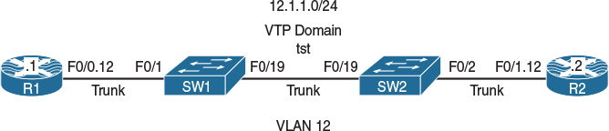
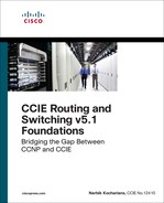
Figure 12-1 Configuring MLS QOS
Figure 12-1 illustrates the topology that will be used in the following tasks.
Task 1
Configure R1 to send all traffic with a COS marking of 1. R2 should be used for verification purposes and should be configured to match on COS values of 0–7 ingress on its f0/1.21 subinterface.
In this task, R2 is configured to match on incoming traffic with COS values of 0–7; this is done so the policy can be tested and verified.
On R2:
R2(config)# class-map cos0
R2(config-cmap)# match cos 0
R2(config)# class-map cos1
R2(config-cmap)# match cos 1
R2(config)# class-map cos2
R2(config-cmap)# match cos 2
R2(config)# class-map cos3
R2(config-cmap)# match cos 3
R2(config)# class-map cos4
R2(config-cmap)# match cos 4
R2(config)# class-map cos5
R2(config-cmap)# match cos 5
R2(config)# class-map cos6
R2(config-cmap)# match cos 6
R2(config)# class-map cos7
R2(config-cmap)# match cos 7
R2(config)# policy-map TST
R2(config-pmap)# class cos0
R2(config-pmap)# class cos1
R2(config-pmap)# class cos2
R2(config-pmap)# class cos3
R2(config-pmap)# class cos4
R2(config-pmap)# class cos5
R2(config-pmap)# class cos6
R2(config-pmap)# class cos7
R2(config)# interface FastEthernet0/1.21
R2(config-subif)# service-policy in TST
The following configures R1 to generate all traffic with a COS value of 1:
On R1:
R1(config)# policy-map TST
R1(config-pmap)# class class-default
R1(config-pmap-c)# set cos 1
R1(config-pmap-c)# interface FastEthernet0/0.12
R1(config-subif)# service-policy out TST
Let’s test the configuration:
On R1:
R1# ping 12.1.1.2
Type escape sequence to abort.
Sending 5, 100-byte ICMP Echos to 12.1.1.2, timeout is 2 seconds:
!!!!!
Success rate is 100 percent (5/5), round-trip min/avg/max = 1/3/4 ms
On R2:
R3# show policy-map interface | section cos1
Class-map: cos1 (match-all)
5 packets, 590 bytes
5 minute offered rate 0 bps
Match: cos 1
You can see that the test was successful. Let’s verify the configuration of mls qos on SW1 and SW2:
On SW1:
SW1# show mls qos
QOS is disabled
QOS ip packet dscp rewrite is enabled
On SW2:
SW2# show mls qos
QOS is disabled
QOS ip packet dscp rewrite is enabled
The test was successful because mls qos was disabled. When mls qos is disabled, the switch does not drop or change the marking of incoming traffic.
Task 2
Enable mls qos on SW1 and ensure that the test in the previous task is still successful:
On SW1:
SW1(config)# mls qos
Let’s verify the configuration:
SW1# show mls qos
QOS is enabled
QOS ip packet dscp rewrite is enabled
When mls qos is enabled, the switch drops the marking of all incoming traffic, unless that marking is trusted on the interface through which the traffic is received. Once mls qos is configured on SW1, SW1 will drop the marking of all incoming traffic; therefore, R2 will see all traffic generated by R1 with a COS value of 0.
If the f0/1 interface of SW1 is configured to trust COS, when SW1 receives the traffic, it will not rewrite or drop the Layer 2 marking.
On R2:
R2# clear counters
Clear "show interface" counters on all interfaces [confirm]
Press Enter to confirm
On R1:
R1# ping 12.1.1.2
Type escape sequence to abort.
Sending 5, 100-byte ICMP Echos to 12.1.1.2, timeout is 2 seconds:
!!!!!
Success rate is 100 percent (5/5), round-trip min/avg/max = 4/4/4 ms
On R2:
R2# show policy-map interface | section cos1
Class-map: cos1 (match-all)
0 packets, 0 bytes
5 minute offered rate 0 bps
Match: cos 1
Note Because the marking was dropped by SW1, R2 no longer sees incoming traffic marked with a COS value of 1. However, if the marking is dropped, it should match COS 0, correct? Let’s verify:
On R2:
R2# show policy-map interface | section cos0
Class-map: cos0 (match-all)
5 packets, 590 bytes
5 minute offered rate 0 bps
Match: cos 0
In order for SW1 to trust the COS marking of incoming traffic, the switchport that R1 is connected to must trust the COS marking in incoming traffic. Let’s configure SW1’s f0/1 interface to trust the COS marking of all incoming traffic:
On SW1:
SW1(config)# interface FastEthernet0/1
SW1(config-if)# mls qos trust cos
On R2:
R2# clear counters
Clear "show interface" counters on all interfaces [confirm]
Press Enter to confirm
On R1:
R1# ping 12.1.1.2 repeat 10
Type escape sequence to abort.
Sending 10, 100-byte ICMP Echos to 12.1.1.2, timeout is 2 seconds:
!!!!!!!!!!
Success rate is 100 percent (10/10), round-trip min/avg/max = 1/3/4 ms
On R2:
R2# show policy-map interface | section cos0
Class-map: cos0 (match-all)
0 packets, 0 bytes
5 minute offered rate 0 bps
Match: cos 0
R2# show policy-map interface | section cos1
Class-map: cos1 (match-all)
10 packets, 1180 bytes
5 minute offered rate 0 bps
Match: cos 1
Task 3
Configure SW1’s f0/1 interface such that it marks all ingress traffic with a COS marking of 2. Do not configure Modular Quality of Service Command Line Interface (MQC) for this purpose.
The following command assigns a COS value of 2:
On SW1:
SW1(config)# interface FastEthernet0/1
SW1(config-if)# mls qos cos 2
Let’s remove the mls qos trust cos command and verify the configuration of the f0/1 interface of SW1:
SW1(config)# interface FastEthernet0/1
SW1(config-if)# no mls qos trust cos
SW1# sh run int f0/1
Building configuration...
Current configuration : 128 bytes
!
interface FastEthernet0/1
switchport trunk encapsulation dot1q
switchport mode trunk
mls qos cos 2
end
Let’s verify the configuration:
On SW1:
SW1# show mls qos interface FastEthernet0/1
FastEthernet0/1
trust state: not trusted
trust mode: not trusted
trust enabled flag: ena
COS override: dis
default COS: 2
DSCP Mutation Map: Default DSCP Mutation Map
Trust device: none
qos mode: port-based
Now we can test the configuration:
On R2:
R2# clear counters
Clear "show interface" counters on all interfaces [confirm]
Press Enter to confirm
On R1:
R1# ping 12.1.1.2 rep 20
Type escape sequence to abort.
Sending 20, 100-byte ICMP Echos to 12.1.1.2, timeout is 2 seconds:
!!!!!!!!!!!!!!!!!!!!
Success rate is 100 percent (20/20), round-trip min/avg/max = 1/3/4 ms
On R2:
R2# show policy-map interface | section cos0
Class-map: cos0 (match-all)
20 packets, 2360 bytes
5 minute offered rate 1000 bps
Match: cos 0
R2# show policy-map interface | section cos1
Class-map: cos1 (match-all)
0 packets, 0 bytes
5 minute offered rate 0 bps
Match: cos 1
R2# show policy-map interface | section cos2
Class-map: cos2 (match-all)
0 packets, 0 bytes
5 minute offered rate 0 bps
Match: cos 2
The mls qos cos 2 command on its own does nothing. It should be combined with either mls qos cos override or mls qos trust cos. When it’s combined with MLS qos trust cos, only the untagged traffic is affected, but if it is combined with mls qos cos override, then all traffic (tagged or untagged) is affected. Tagged traffic is traffic that contains the VLAN ID.
Let’s test this by adding mls qos trust cos to the f0/1 interface of SW1 and view the result:
On SW1:
SW1(config)# interface FastEthernet0/1
SW1(config-if)# mls qos trust cos
On R2:
R2# clear counters
Clear "show interface" counters on all interfaces [confirm]
Press Enter to confirm
On R1:
R1# ping 12.1.1.2 rep 20
Type escape sequence to abort.
Sending 20, 100-byte ICMP Echos to 12.1.1.2, timeout is 2 seconds:
!!!!!!!!!!!!!!!!!!!!
Success rate is 100 percent (20/20), round-trip min/avg/max = 1/3/4 ms
On R2:
R2# show policy-map interface | section cos0
Class-map: cos0 (match-all)
0 packets, 0 bytes
5 minute offered rate 0 bps
Match: cos 0
R2# show policy-map interface | section cos1
Class-map: cos1 (match-all)
20 packets, 2360 bytes
5 minute offered rate 0 bps
Match: cos 1
R2# show policy-map interface | section cos2
Class-map: cos2 (match-all)
0 packets, 0 bytes
5 minute offered rate 0 bps
Match: cos 2
Note Even though the interface is configured with mls qos cos 2 and mls qos trust cos, the traffic coming in on that interface is not affected. To mark all traffic with a COS marking of 2, which means tagged or untagged, the port must be configured to override the existing COS.
The following command configures the switch port with the mls qos cos override command:
On SW1:
SW1(config)# interface FastEthernet0/1
SW1(config-if)# mls qos cos override
Let’s look at the configuration on the f0/1 interface of SW1:
On SW1:
SW1# show run interface FastEthernet0/1
Building configuration...
Current configuration : 131 bytes
!
interface FastEthernet0/1
switchport trunk encapsulation dot1q
switchport mode trunk
mls qos cos 2
mls qos cos override
end
You can see that the mls qos trust cos command was auto-replaced with the mls qos cos override command. Let’s test and verify:
On R2:
R2# clear counters
Clear "show interface" counters on all interfaces [confirm]
Press Enter to confirm
On R1:
R1# ping 12.1.1.2 rep 20
Type escape sequence to abort.
Sending 20, 100-byte ICMP Echos to 12.1.1.2, timeout is 2 seconds:
!!!!!!!!!!!!!!!!!!!!
Success rate is 100 percent (20/20), round-trip min/avg/max = 1/3/4 ms
On R2:
R2# show policy-map interface | section cos0
Class-map: cos0 (match-all)
0 packets, 0 bytes
5 minute offered rate 0 bps
Match: cos 0
R2# show policy-map interface | section cos1
Class-map: cos1 (match-all)
0 packets, 0 bytes
5 minute offered rate 0 bps
Match: cos 1
R2# show policy-map interface | section cos2
Class-map: cos2 (match-all)
20 packets, 2360 bytes
5 minute offered rate 1000 bps
Match: cos 2
You can see that the traffic generated by R1 that had a COS value of 1 was overridden with a COS value of 2.
What if the f0/1 interface of SW1 is configured with mls qos trust cos and mls qos cos 2 and we want the traffic generated by R1 to be rewritten to a COS value of 2? Can we accomplish this task by configuring R1?
Let’s test and verify:
On SW1:
SW1(config)# interface FastEthernet0/1
SW1(config-if)# mls qos trust cos
Now let’s verify the configuration:
SW1# show run interface FastEthernet0/1
Building configuration...
Current configuration : 128 bytes
!
interface FastEthernet0/1
switchport trunk encapsulation dot1q
switchport mode trunk
mls qos cos 2
mls qos trust cos
end
Note The mls qos trust cos command automatically removed the mls qos cos override command.
We know that with the preceding configuration, only untagged traffic will be affected, but how do we untag the traffic generated by R1 without having to reconfigure R1?
On R1:
R1(config)# interface FastEthernet0/0.12
R1(config-subif)# encapsulation dot1Q 100 native
Note With the native keyword, we are instructing R1 to remove the tag; therefore, the value before native is irrelevant.
On R2:
R2# clear counters
Clear "show interface" counters on all interfaces [confirm]
Press Enter to confirm
On R1:
R1# ping 12.1.1.2 rep 20
Type escape sequence to abort.
Sending 20, 100-byte ICMP Echos to 12.1.1.2, timeout is 2 seconds:
!!!!!!!!!!!!!!!!!!!!
Success rate is 100 percent (20/20), round-trip min/avg/max = 1/3/4 ms
On R2:
R2# show policy-map interface | section cos0
Class-map: cos0 (match-all)
0 packets, 0 bytes
5 minute offered rate 0 bps
Match: cos 0
R2# show policy-map interface | section cos1
Class-map: cos1 (match-all)
0 packets, 0 bytes
5 minute offered rate 0 bps
Match: cos 1
R2# show policy-map interface | section cos2
Class-map: cos2 (match-all)
20 packets, 2360 bytes
5 minute offered rate 0 bps
Match: cos 2
Because the traffic is no longer tagged, the traffic generated by R1 with a COS value of 1 is rewritten to a COS value of 2.
Erase the startup configuration on R1–R3 and on SW1 and SW2 and reload these routers and switches before proceeding to the next lab.
Lab 12-2: Differential Service Code Point-Mutation
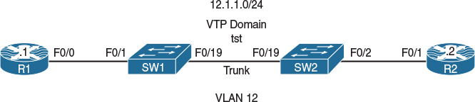
Figure 12-2 Configuring DSCP-Mutation
Figure 12-2 illustrates the topology that will be used in the following tasks.
Task 1
Configure an MQC on R1 such that all packets going out of its F0/0 interface are marked with a DSCP value of 1. For verification purposes, R2’s F0/1 interface should be configured to match on DSCP values of 0–7 for all ingress traffic. Ensure that mls qos is disabled on both switches.
On both switches:
SWx# show mls qos
QOS is disabled
QOS ip packet dscp rewrite is enabled
The following configuration marks all egress traffic with a DSCP value of 1:
On R1:
R1(config)# policy-map TST
R1(config-pmap)# class class-default
R1(config-pmap-c)# set ip dscp 1
R1(config)# interface FastEthernet0/0
R1(config-if)# service-policy out TST
The following configuration is done for verification and testing purposes:
On R2:
R2(config)# class-map dscp0
R2(config-cmap)# match ip dscp 0
R2(config)# class-map dscp1
R2(config-cmap)# match ip dscp 1
R2(config)# class-map dscp2
R2(config-cmap)# match ip dscp 2
R2(config)# class-map dscp3
R2(config-cmap)# match ip dscp 3
R2(config)# class-map dscp4
R2(config-cmap)# match ip dscp 4
R2(config)# class-map dscp5
R2(config-cmap)# match ip dscp 5
R2(config)# class-map dscp6
R2(config-cmap)# match ip dscp 6
R2(config)# class-map dscp7
R2(config-cmap)# match ip dscp 7
R2(config)# policy-map TST
R2(config-pmap)# class dscp0
R2(config-pmap)# class dscp1
R2(config-pmap)# class dscp2
R2(config-pmap)# class dscp3
R2(config-pmap)# class dscp4
R2(config-pmap)# class dscp5
R2(config-pmap)# class dscp6
R2(config-pmap)# class dscp7
R2(config)# interface FastEthernet0/1
R2(config-if)# service-policy in TST
Let’s test the configuration:
On R1:
R1# ping 12.1.1.2 rep 10
Type escape sequence to abort.
Sending 10, 100-byte ICMP Echos to 12.1.1.2, timeout is 2 seconds:
!!!!!!!!!!
Success rate is 100 percent (10/10), round-trip min/avg/max = 1/3/4 ms
On R2:
R2# show policy-map inter | section dscp1
Class-map: dscp1 (match-all)
10 packets, 1140 bytes
5 minute offered rate 0 bps
Match: ip dscp 1
Task 2
Configure SW2 such that if the incoming traffic is marked with a DSCP value of 1, it is overwritten with a DSCP value of 60. Do not configure a class map or a policy map to accomplish this task. Use R2 to verify the configuration.
DSCP-mutation can be configured on SW2 to accomplish this task. Configuring DSCP-mutation requires four steps.
Step 1
First, mls qos must be enabled:
On SW2:
SW2(config)# mls qos
Once mls qos is enabled, the marking of all traffic is zeroed out, meaning that incoming traffic that is marked with any DSCP value will match to a DSCP value of 0. This can be seen on R2. The following proves this point:
On SW2:
SW2# show mls qos
QOS is enabled
QOS ip packet dscp rewrite is enabled
Let’s test the configuration:
On R2:
R2# clear counters
Clear "show interface" counters on all interfaces [confirm]
Press Enter to confirm
On R1:
R1# ping 12.1.1.2 rep 100
Type escape sequence to abort.
Sending 100, 100-byte ICMP Echos to 12.1.1.2, timeout is 2 seconds:
!!!!!!!!!!!!!!!!!!!!!!!!!!!!!!!!!!!!!!!!!!!!!!!!!!!!!!!!!!!!!!!!!!!!!!
!!!!!!!!!!!!!!!!!!!!!!!!!!!!!!
Success rate is 100 percent (100/100), round-trip min/avg/max = 1/1/4 ms
Now we can verify the configuration:
On R2:
R2# show policy-map interface | section dscp1
Class-map: DSCP1 (match-all)
0 packets, 0 bytes
5 minute offered rate 0 bps
Match: dscp 1
R3# show policy-map interface | section dscp0
Class-map: DSCP0 (match-all)
100 packets, 11400 bytes
5 minute offered rate 2000 bps
Match: dscp default (0)
Step 2
If mls qos trust dscp is not configured, the configuration will not have any effect on the packets because SW2 will drop the marking of all incoming traffic:
On SW2:
SW2(config)# interface FastEthernet0/19
SW2(config-if)# mls qos trust dscp
Let’s verify this information:
On SW2:
SW2# show mls qos interface FastEthernet0/19 | include trust state
trust state: trust dscp
Note If COS was trusted, the output of the preceding command would have stated trust state: trust cos since only DSCP is trusted. In other words, the trust state is DSCP.
On R2:
R2# clear counters
Clear "show interface" counters on all interfaces [confirm]
Press Enter to confirm
On R1:
R1# ping 12.1.1.2 rep 100
Type escape sequence to abort.
Sending 100, 100-byte ICMP Echos to 12.1.1.2, timeout is 2 seconds:
!!!!!!!!!!!!!!!!!!!!!!!!!!!!!!!!!!!!!!!!!!!!!!!!!!!!!!!!!!!!!!!!!!!!!!
!!!!!!!!!!!!!!!!!!!!!!!!!!!!!!
Success rate is 100 percent (100/100), round-trip min/avg/max = 1/1/4 ms
On R2:
R2# show policy-map interface | section dscp0
Class-map: DSCP0 (match-all)
0 packets, 0 bytes
5 minute offered rate 0 bps
Match: dscp default (0)
R2# show policy-map interface | section dscp1
Class-map: DSCP1 (match-all)
100 packets, 11400 bytes
5 minute offered rate 0 bps
Match: dscp 1
Step 3
In this step, a custom DSCP-mutation map is configured. Remember that if this custom mapping is not configured, the default DSCP-mutation map will be used.
The default DSCP-mutation map cannot be changed, and it is configured as “one to one,” meaning that the DSCP marking in the incoming traffic will always match the DSCP marking in the outgoing traffic.
In this step, a custom DSCP-mutation map named TST is configured. This custom DSCP-mutation map maps the incoming DSCP value (in this case 1) to an outgoing DSCP value of 60.
Let’s look at the default DSCP-mutation map:
SW2# show mls qos map dscp-mutation
Dscp-dscp mutation map:
Default DSCP Mutation Map:
d1 : d2 0 1 2 3 4 5 6 7 8 9
---------------------------------------
0 : 00 01 02 03 04 05 06 07 08 09
1 : 10 11 12 13 14 15 16 17 18 19
2 : 20 21 22 23 24 25 26 27 28 29
3 : 30 31 32 33 34 35 36 37 38 39
4 : 40 41 42 43 44 45 46 47 48 49
5 : 50 51 52 53 54 55 56 57 58 59
6 : 60 61 62 63
Note that the “d1” column specifies the most significant digit of the DSCP value of incoming packets, whereas the “d2” row specifies the least significant digit of the DSCP value in incoming packets.
The intersection of the “d1” and “d2” values in the body of the output provides the DSCP value of the outgoing traffic.
Note The output of the preceding show command reveals that the incoming DSCP value of 1 is rewritten to the outgoing DSCP value of 1.
Let’s configure a custom DSCP-mutation map called “TST” that maps the incoming DSCP value of 1 to an outgoing DSCP value of 60:
SW2(config)# mls qos map dscp-mutation TST 1 to 60
Let’s verify the configuration:
On SW2:
SW2# show mls qos map dscp-mutation TST
Dscp-dscp mutation map:
TST:
d1 : d2 0 1 2 3 4 5 6 7 8 9
---------------------------------------
0 : 00 60 02 03 04 05 06 07 08 09
1 : 10 11 12 13 14 15 16 17 18 19
2 : 20 21 22 23 24 25 26 27 28 29
3 : 30 31 32 33 34 35 36 37 38 39
4 : 40 41 42 43 44 45 46 47 48 49
5 : 50 51 52 53 54 55 56 57 58 59
6 : 60 61 62 63
Once the custom DSCP-mutation map is configured, it must be applied to the F0/19 interface (trunk interface) of SW2:
SW2(config)# interface FastEthernet0/19
SW2(config-if)# mls qos dscp-mutation TST
Let’s verify the configuration:
On SW2:
SW2# show mls qos interface FastEthernet0/19
FastEthernet0/19
trust state: trust dscp
trust mode: trust dscp
trust enabled flag: ena
COS override: dis
default COS: 0
DSCP Mutation Map: TST
Trust device: none
qos mode: port-based
Step 4
In the final step of this configuration, you must ensure that DSCP rewrites are enabled. If this feature is disabled, the DSCP marking will not be rewritten.
Let’s verify whether DSCP rewrites are enabled:
On SW2:
SW2# Show mls qos
QOS is enabled
QOS ip packet dscp rewrite is enabled
By default, DSCP rewrites are enabled only if mls qos is enabled. I recommend that you enter the following command and not rely on memory to check to see if it is enabled:
SW2(config)# mls qos rewrite ip dscp
Let’s test and see if the incoming DSCP value of 1 is rewritten to a DSCP value of 60 (remember that on R3 we need to match on DSCP 60 so we can test and verify the configuration):
On R2:
R2(config)# class-map dscp60
R2(config-cmap)# match ip dscp 60
R2(config)# policy-map TST
R2(config-pmap)# class dscp60
When we add a class (or classes) to an existing policy map, the new classes are added to the end of all the classes within that policy map. Let’s look at this:
On R2:
R2# show policy-map TST
Policy Map TST
Class dscp0
Class dscp1
Class dscp2
Class dscp3
Class dscp4
Class dscp5
Class dscp6
Class dscp7
Class dscp60
Now let’s test the configuration:
On R2:
R2# clear counters
Clear "show interface" counters on all interfaces [confirm]
Press Enter to confirm
On R1:
R1# ping 12.1.1.2 rep 60
Type escape sequence to abort.
Sending 60, 100-byte ICMP Echos to 12.1.1.2, timeout is 2 seconds:
!!!!!!!!!!!!!!!!!!!!!!!!!!!!!!!!!!!!!!!!!!!!!!!!!!!!!!!!!!!!
Success rate is 100 percent (60/60), round-trip min/avg/max = 1/1/4 ms
On R2:
R2# show policy-map interface | section dscp60
Class-map: DSCP60 (match-all)
60 packets, 6840 bytes
5 minute offered rate 2000 bps
Match: ip dscp 60
Let’s disable the rewrites:
On SW2:
SW2(config)# no mls qos rewrite ip dscp
Now let’s verify the configuration:
On SW2:
SW2# Show mls qos
QOS is enabled
QOS ip packet dscp rewrite is disabled
We also need to test the configuration:
On R2:
R2# clear counters
Clear "show interface" counters on all interfaces [confirm]
Press Enter to confirm
On R1:
R1# ping 12.1.1.2 rep 10
Type escape sequence to abort.
Sending 100, 100-byte ICMP Echos to 12.1.1.2, timeout is 2 seconds:
!!!!!!!!!!
Success rate is 100 percent (10/10), round-trip min/avg/max = 1/1/4 ms
On R2:
R2# show policy-map interface | section dscp60
Class-map: dscp60 (match-all)
0 packets, 0 bytes
5 minute offered rate 0 bps
Match: ip dscp 60
R2# show policy-map interface | section dscp1
Class-map: dscp1 (match-all)
10 packets, 1140 bytes
5 minute offered rate 0 bps
Match: ip dscp 1
Note Because the rewriting of DSCP markings is disabled, the incoming DSCP value was not modified. Let’s enable IP DSCP rewrites:
On SW2:
SW2(config)# mls qos rewrite ip dscp
Erase the startup configuration on R1–R3 and SW1 and SW2 and reload these routers and switches before proceeding to the next lab.
Lab 12-3: DSCP-COS Mapping
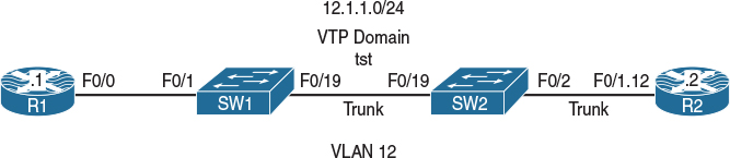
Figure 12-3 Configuring DSCP-COS Mapping
Figure 12-3 illustrates the topology that will be used in the following tasks.
Task 1
For testing and verification of this lab, configure R2 to match on incoming COS markings of 0–7 using an MQC; this policy should be applied inbound to R2’s F0/1.12 subinterface.
On R2:
R2(config)# class-map cos0
R2(config-cmap)# match cos 0
R2(config)# class-map cos1
R2(config-cmap)# match cos 1
R2(config)# class-map cos2
R2(config-cmap)# match cos 2
R2(config)# class-map cos3
R2(config-cmap)# match cos 3
R2(config)# class-map cos4
R2(config-cmap)# match cos 4
R2(config)# class-map cos5
R2(config-cmap)# match cos 5
R2(config)# class-map cos6
R2(config-cmap)# match cos 6
R2(config)# class-map cos7
R2(config-cmap)# match cos 7
R2(config)# policy-map TST
R2(config-pmap)# class cos0
R2(config-pmap)# class cos1
R2(config-pmap)# class cos2
R2(config-pmap)# class cos3
R2(config-pmap)# class cos4
R2(config-pmap)# class cos5
R2(config-pmap)# class cos6
R2(config-pmap)# class cos7
R2(config)# interface FastEthernet0/1.21
R2(config-subif)# service-policy in TST
Task 2
Configure R1 such that it marks all outgoing traffic with a DSCP value of 5:
On R1:
R1(config)# policy-map TST
R1(config-pmap)# class class-default
R1(config-pmap-c)# set ip dscp 5
R1(config)# interface FastEthernet0/0
R1(config-if)# service-policy out TST
Task 3
Configure SW2 such that it rewrites the incoming traffic marked with a DSCP value of 5 to an outgoing COS value of 1.
Before configuring this task, you need to display the default dscp-cos mapping using the following command:
On SW2:
SW2# show mls qos map dscp-cos
Dscp-cos map:
d1 : d2 0 1 2 3 4 5 6 7 8 9
---------------------------------------
0 : 00 00 00 00 00 00 00 00 01 01
1 : 01 01 01 01 01 01 02 02 02 02
2 : 02 02 02 02 03 03 03 03 03 03
3 : 03 03 04 04 04 04 04 04 04 04
4 : 05 05 05 05 05 05 05 05 06 06
5 : 06 06 06 06 06 06 07 07 07 07
6 : 07 07 07 07
Note The output of the preceding show command displays the default DSCP-to-COS mapping, which means that if the mls qos trust dscp command is configured, then the DSCP markings of incoming packets are mapped to the outgoing COS value according to the DSCP-COS map.
The incoming DSCP values are shown in the “d1” column and the “d2” row, whereas the outgoing COS values are identified in the body of this display; this is the intersection of the “d1” column and the “d2” row.
Note Every eight DSCP values are mapped to a single COS value. Because there is no default mapping for dscp-cos, this mapping can affect the entire switch.
By default, an incoming DSCP value of 5 is mapped to an outgoing COS value of 0. To accomplish this task, you have to modify this mapping so the incoming DSCP value of 5 is mapped to an outgoing COS value of 1. Figure 12-4 illustrates this process.
Note The DSCP marking is not changed at all; therefore, you are rewriting the outgoing COS value based on the incoming DSCP value.
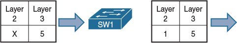
Figure 12-4 Modifying the Mapping of DSCP Values to COS Values
To test and verify the default configuration, the following command must be configured so that the incoming DSCP values are trusted. If this is not configured, the incoming DSCP values will not be mapped to an outgoing COS value.
On SW2:
SW2(config)# mls qos
SW2(config)# interface FastEthernet0/19
SW2(config-if)# mls qos trust dscp
Let’s verify the configuration:
On SW2:
SW2# show mls qos interface FastEthernet0/19 | include trust state
trust state: trust dscp
To test the configuration, a ping is generated from R1 with a repeat count of 50 that’s verified on R2:
On R1:
R1# ping 12.1.1.2 repeat 50
Type escape sequence to abort.
Sending 50, 100-byte ICMP Echos to 12.1.1.2, timeout is 2 seconds:
!!!!!!!!!!!!!!!!!!!!!!!!!!!!!!!!!!!!!!!!!!!!!!!!!!
Success rate is 100 percent (50/50), round-trip min/avg/max = 1/3/4 ms
Let’s verify the configuration:
On R2:
R2# show policy-map interface | section cos0
Class-map: cos0 (match-all)
50 packets, 5900 bytes
5 minute offered rate 0 bps
Match: cos 0
Note DSCP 5 is mapped to a COS value of 0 because of the default mapping that is in use.
In the next step, the default dscp-cos mapping is changed to map an incoming DSCP value of 5 to an outgoing COS value of 1:
On SW2:
SW2(config)# mls qos map dscp-cos 5 to 1
Note The first value (5) is the DSCP value in the incoming packets, and the second value (1) is the COS value in the outgoing packets.
Let’s now test and verify the configuration:
On R2:
R3# clear counters
Clear "show interface" counters on all interfaces [confirm]
Press Enter to confirm
On R1:
R1# ping 12.1.1.2 repeat 50
Type escape sequence to abort.
Sending 50, 100-byte ICMP Echos to 12.1.1.2, timeout is 2 seconds:
!!!!!!!!!!!!!!!!!!!!!!!!!!!!!!!!!!!!!!!!!!!!!!!!!!
Success rate is 100 percent (50/50), round-trip min/avg/max = 1/3/4 ms
Note Incoming packets that are marked with a DSCP value of 5 are mapped to an outgoing COS value of 1 and not 0:
On R2:
R2# show policy-map interface | section cos0
Class-map: cos0 (match-all)
0 packets, 0 bytes
5 minute offered rate 0 bps
Match: cos 0
R2# show policy-map interface | section cos1
Class-map: cos1 (match-all)
50 packets, 5900 bytes
5 minute offered rate 0 bps
Match: cos 1
Erase the startup configuration on R1–R3 and SW1 and SW2 and reload these routers and switches before proceeding to the next lab.
Lab 12-4: COS-DSCP Mapping
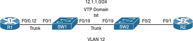
Figure 12-5 Configuring COS-DSCP Mapping
Figure 12-5 illustrates the topology that will be used in the following tasks.
Task 1
Configure the F0/1 interface of R2 to match all its incoming traffic marked as DSCP 0, 30, or 56 using an MQC:
On R2:
R2(config)# class-map d0
R2(config-cmap)# match ip dscp 0
R2(config-cmap)# class-map d30
R2(config-cmap)# match ip dscp 30
R2(config-cmap)# class-map d56
R2(config-cmap)# match ip dscp 56
R2(config)# policy-map TST
R2(config-pmap)# class d0
R2(config-pmap-c)# class d30
R2(config-pmap-c)# class d56
R2(config-pmap-c)# interface FastEthernet0/1
R2(config-if)# service-policy in TST
Task 2
Configure the F0/1 interface of SW1 so that it marks all incoming traffic with a COS value of 7. This should apply to both tagged and untagged traffic.
On SW1:
SW2(config)# mls qos
SW2(config)# interface FastEthernet0/1
SW2(config-if)# mls qos cos 7
SW2(config-if)# mls qos cos override
Task 3
Configure the F0/19 interface of SW2 so that it maps incoming traffic with a COS value of 7 to outgoing traffic with a DSCP value of 30.
Before configuring this task, you should display the default mapping. The following command reveals the default mapping of COS to DSCP:
On SW2:
SW2# show mls qos map cos-dscp
Cos-dscp map:
cos: 0 1 2 3 4 5 6 7 ←← The Cos value of incoming packets
--------------------------------
dscp: 0 8 16 24 32 40 48 56 ← The DSCP value of outgoing packets
The preceding displays the existing COS-to-DSCP map. You can see that COS value of 0 is mapped to an outgoing DSCP value of 0, and an incoming COS value of 1 is mapped to a DSCP value of 8, and so forth.
To test this, R1 will ping R2 because the switchport that R1 is connected to is configured to assign a COS value of 7 to all incoming traffic; it should be matched to a DSCP value of 56 on R2. Before this can be accomplished, mls qos must be enabled on SW2:
On SW2:
SW1(config)# mls qos
SW1(config)# interface FastEthernet0/19
SW1(config-if)# mls qos trust cos
Let’s verify the configuration:
On SW2:
SW2# Show mls qos
QOS is enabled
QOS ip packet dscp rewrite is enabled
SW2# show mls qos interface FastEthernet0/19 | include trust state
trust state: trust cos
Now we can test the configuration:
On R1:
R1# ping 12.1.1.2 rep 30
Type escape sequence to abort.
Sending 30, 100-byte ICMP Echos to 12.1.1.2, timeout is 2 seconds:
!!!!!!!!!!!!!!!!!!!!!!!!!!!!!!
Success rate is 100 percent (30/30), round-trip min/avg/max = 1/2/4 ms
On R2:
R2# show policy-map interface | section d56
Class-map: d56 (match-all)
30 packets, 3420 bytes
5 minute offered rate 0 bps
Match: ip dscp cs7 (56)
To configure this task, you need to change the default mapping. SW2 should be configured as follows:
COS 0 COS 1 COS 2
COS 3 COS 4 COS 5 COS 6 COS 7
On SW2:
SW2(config)# mls qos map cos-dscp 0 8 16 24 32 40 48 30
For this command, you must configure all eight DSCP values. The values entered are the DSCP values, and the position of the DSCP values identifies the COS values. The first DSCP value (0) maps to a COS value of 0, and the second DSCP value (8) maps to a COS value of 1. The third DSCP value (16) maps to a COS value of 2, the fourth DSCP value (24) maps to a COS value of 3, the fifth DSCP value (32) maps to a COS value of 4, the sixth DSCP value (40) maps to a COS value of 5, the seventh DSCP value (48) maps to a COS value of 6, and the last DSCP value (30) maps to a COS value of 7.
Let’s verify and test the configuration:
On SW2:
SW1# show mls qos map cos-dscp
Cos-dscp map:
cos: 0 1 2 3 4 5 6 7
--------------------------------
dscp: 0 8 16 24 32 40 48 30
On R2:
R2# clear counters
Clear "show interface" counters on all interfaces [confirm]
Press Enter to confirm
On R1:
R1# ping 12.1.1.2 rep 30
Type escape sequence to abort.
Sending 30, 100-byte ICMP Echos to 12.1.1.2, timeout is 2 seconds:
!!!!!!!!!!!!!!!!!!!!!!!!!!!!!!
Success rate is 100 percent (30/30), round-trip min/avg/max = 1/2/4 ms
On R2:
R2# show policy-map interface | section d56
Class-map: d56 (match-all)
0 packets, 0 bytes
5 minute offered rate 0 bps
Match: ip dscp cs7 (56)
R2# show policy-map interface | section d30
Class-map: d30 (match-all)
30 packets, 3420 bytes
5 minute offered rate 2000 bps
Match: ip dscp af33 (30)
Erase the startup configuration on R1–R3 and SW1 and SW2 and reload these routers and switches before proceeding to the next lab.
Lab 12-5: IP-Precedence-DSCP Mapping
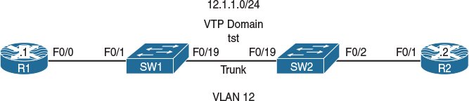
Figure 12-6 Configuring IP-Precedence-DSCP Mapping
Figure 12-6 illustrates the topology that will be used in the following tasks.
Task 1
Configure SW2 so that it overwrites the IP-Precedence value of 5 in incoming traffic with a DSCP value of 50 in the outgoing traffic. Configure R2 to match on DSCP markings of 0, 5, and 40 in incoming packets; this should be done for testing purpose.
On R2:
R2(config)# class-map d0
R2(config-cmap)# match ip dscp 0
R2(config)# class-map d5
R2(config-cmap)# match ip dscp 5
R2(config)# class-map d50
R2(config-cmap)# match ip dscp 50
R2(config)# policy-map TST
R2(config-pmap)# class d0
R2(config-pmap)# class d5
R2(config-pmap)# class d50
R2(config)# interface FastEthernet0/1
R2(config-if)# service-policy in TST
Before this task is configured, the existing IP-Precedence-to-DSCP mapping should be examined:
On SW2:
SW2# Show mls qos map ip-prec-dscp
IpPrecedence-dscp map:
ipprec: 0 1 2 3 4 5 6 7 ← The IPP value of incoming packets
--------------------------------
dscp: 0 8 16 24 32 40 48 56 ← The DSCP value of Outgoing packets
Note The IP-Precedence value of 0 is mapped to an outgoing DSCP value of 0, and the incoming IP-Precedence value of 1 is mapped to a DSCP value of 8, and so forth.
Configure the following to test this default mapping:
![]() Configure R1 to mark all egress traffic with an IP-Precedence value of 5.
Configure R1 to mark all egress traffic with an IP-Precedence value of 5.
![]() Enable mls qos on both switches.
Enable mls qos on both switches.
![]() The F0/1 interface of SW1 and the F0/19 interface of SW2 should be configured to trust IP-Precedence.
The F0/1 interface of SW1 and the F0/19 interface of SW2 should be configured to trust IP-Precedence.
Ping R2 from R1. If the devices are configured correctly, R2 should see the ping traffic from R1 match to a DSCP value of 40.
On R1:
R1(config)# policy-map TST
R1(config-pmap)# class class-default
R1(config-pmap-c)# Set ip precedence 5
R1(config)# interface FastEthernet0/0
R1(config-if)# service-policy output TST
On SW1:
SW1(config)# mls qos
SW1(config)# interface FastEthernet0/1
SW1(config-if)# mls qos trust ip-precedence
On SW2:
SW2(config)# mls qos
SW2(config)# interface FastEthernet0/19
SW2(config-if)# mls qos trust ip-precedence
Let’s test and verify the configuration:
On R2:
R2# clear counters
Clear "show interface" counters on all interfaces [confirm]
Press Enter to confirm
On R1:
R1# ping 12.1.1.2 rep 50
Type escape sequence to abort.
Sending 50, 100-byte ICMP Echos to 12.1.1.2, timeout is 2 seconds:
!!!!!!!!!!!!!!!!!!!!!!!!!!!!!!!!!!!!!!!!!!!!!!!!!!
Success rate is 100 percent (50/50), round-trip min/avg/max = 1/3/8 ms
On R2:
R1# show policy-map interface | section d40
Class-map: D40 (match-all)
50 packets, 5700 bytes
5 minute offered rate 0 bps
Match: ip dscp cs5 (40)
Note All traffic is matched to a DSCP value of 40 on R1.
Let’s configure this task:
On SW2:
SW2(config)# mls qos map ip-prec-dscp 0 8 16 24 32 50 48 56
Now we can verify the configuration:
SW2# show mls qos map ip-prec-dscp
IpPrecedence-dscp map:
ipprec: 0 1 2 3 4 5 6 7
--------------------------------
dscp: 0 8 16 24 32 50 48 56
Let’s test the configuration:
On R2:
R2# clear counters
Clear "show interface" counters on all interfaces [confirm]
Press Enter to confirm
On R1:
R1# ping 12.1.1.2 rep 50
Type escape sequence to abort.
Sending 50, 100-byte ICMP Echos to 12.1.1.2, timeout is 2 seconds:
!!!!!!!!!!!!!!!!!!!!!!!!!!!!!!!!!!!!!!!!!!!!!!!!!!
Success rate is 100 percent (50/50), round-trip min/avg/max = 1/3/4 ms
On R2:
R2# show policy-map interface | section d50
Class-map: d50 (match-all)
50 packets, 5700 bytes
5 minute offered rate 2000 bps
Match: ip dscp 50
Erase the startup config and reload these devices with a clean configuration before proceeding to the next lab.
Lab 12-6: Match Input-Interface and Match NOT
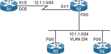
Figure 12-7 Configuring Input-Interface and Match NOT
Figure 12-7 illustrates the topology that will be used in the following tasks.
Task 1
Configure R4’s f0/0 to mark all egress traffic with a DSCP value of 40:
On R4:
R4(config)# policy-map tst
R4(config-pmap)# class class-default
R4(config-pmap-c)# Set ip dscp 40
R4(config)# interface FastEthernet0/0
R4(config-if)# service-policy out tst
Let’s verify and test the configuration:
On R4:
R4# show policy-map interface
FastEthernet0/0
Service-policy output: tst
Class-map: class-default (match-any)
12 packets, 1304 bytes
5 minute offered rate 0 bps, drop rate 0 bps
Match: any
QOS Set
dscp cs5
Packets marked 0
To test the configuration, a class map is configured to match on the DSCP value of 40, and a policy-map is configured that references the class map. The policy map is applied to the F0/0 interface of R2 inbound.
R2(config)# class-map DSCP40
R2(config-cmap)# match ip dscp 40
R2(config)# policy-map tst
R2(config-pmap)# class DSCP40
R2(config)# interface FastEthernet0/0
R2(config-if)# service-policy in tst
To test this configuration, R4 will ping R2. The result is verified on R2:
On R2:
R2# show policy-map interface
FastEthernet0/0
Service-policy input: tst
Class-map: DSCP40 (match-all)
0 packets, 0 bytes
5 minute offered rate 0 bps
Match: ip dscp cs5 (40)
Class-map: class-default (match-any)
0 packets, 0 bytes
5 minute offered rate 0 bps, drop rate 0 bps
Match: any
On R4:
R4# ping 10.1.1.2 rep 40
Type escape sequence to abort.
Sending 40, 100-byte ICMP Echos to 10.1.1.2, timeout is 2 seconds:
!!!!!!!!!!!!!!!!!!!!!!!!!!!!!!!!!!!!!!!!
Success rate is 100 percent (40/40), round-trip min/avg/max = 1/3/4 ms
On R2:
R2# show policy-map interface
FastEthernet0/0
Service-policy input: tst
Class-map: DSCP40 (match-all)
0 packets, 0 bytes
5 minute offered rate 0 bps
Match: ip dscp cs5 (40)
Class-map: class-default (match-any)
40 packets, 4560 bytes
5 minute offered rate 2000 bps, drop rate 0 bps
Match: any
The output of the preceding show command reveals that 40 packets were matched to class class-default and not DSCP 40. What went wrong?
Well, R2, R3, and R4 are connected to each other via SW1, and if SW1 has mls qos enabled, it will drop all the markings. Let’s check mls qos on SW1:
On SW1:
SW1# show mls qos
QOS is enabled
QOS ip packet dscp rewrite is enabled
SW1(config)# no mls qos
Let’s test and verify the configuration:
On R2:
R2# clear counters
Clear "show interface" counters on all interfaces [confirm]
Press Enter to confirm
On R4:
R4# ping 10.1.1.2 rep 40
Type escape sequence to abort.
Sending 40, 100-byte ICMP Echos to 10.1.1.2, timeout is 2 seconds:
!!!!!!!!!!!!!!!!!!!!!!!!!!!!!!!!!!!!!!!!
Success rate is 100 percent (40/40), round-trip min/avg/max = 1/3/4 ms
On R2:
R2# show policy-map interface
FastEthernet0/0
Service-policy input: tst
Class-map: DSCP40 (match-all)
40 packets, 4560 bytes
5 minute offered rate 0 bps
Match: ip dscp cs5 (40)
Class-map: class-default (match-any)
0 packets, 0 bytes
5 minute offered rate 0 bps, drop rate 0 bps
Match: any
You can see that 40 packets matched on the class that matches the DSCP value 40. Let’s remove the MQC configured on R2 and proceed to the next task:
On R2:
R2(config)# interface FastEthernet0/0
R2(config-if)# no service-policy in tst
R2(config)# no policy-map tst
R2(config)# no class-map DSCP40
Task 2
Configure R2 based on the following policy:
![]() The ingress traffic through the s1/1 interface should be classified and marked with a DSCP value of 10.
The ingress traffic through the s1/1 interface should be classified and marked with a DSCP value of 10.
![]() The ingress traffic through the f0/0 interface should be classified and marked with a DSCP value of 20. This policy should not affect any ingress traffic that is marked with a DSCP value of 40. Do not configure an access list to accomplish this task.
The ingress traffic through the f0/0 interface should be classified and marked with a DSCP value of 20. This policy should not affect any ingress traffic that is marked with a DSCP value of 40. Do not configure an access list to accomplish this task.
Let’s configure the policy for the s1/1 interface:
On R2:
R2(config)# class-map S1/1
R2(config-cmap)# match input-interface serial1/1
R2(config)# policy-map TST-S1/1
R2(config-pmap)# class S1/1
R2(config-pmap-c)# set ip dscp 10
R2(config-pmap)# int serial1/1
R2(config-if)# service-policy in TST-S1/1
Finally, let’s configure the policy for the f0/0 interface:
R2(config)# class-map F0/0
R2(config-cmap)# match not dscp 40
R2(config-cmap)# match input-interface FastEthernet0/0
R2(config)# policy-map TST-F0/0
R2(config-pmap)# class F0/0
R2(config-pmap-c)# Set ip dscp 20
R2(config-pmap-c)# interface FastEthernet0/1
R2(config-if)# service-policy in TST-F0/0
Now we need to verify the configuration:
On R2:
R2# show policy-map interface serial1/1
Serial1/1
Service-policy input: TST-S1/1
Class-map: S1/1 (match-all)
0 packets, 0 bytes
5 minute offered rate 0 bps, drop rate 0 bps
Match: input-interface Serial1/1
QOS Set
dscp af11
Packets marked 0
Class-map: class-default (match-any)
0 packets, 0 bytes
5 minute offered rate 0 bps, drop rate 0 bps
Match: any
R2# show policy-map interface FastEthernet0/0
FastEthernet0/0
Service-policy input: TST-F0/0
Class-map: F0/0 (match-all)
0 packets, 0 bytes
5 minute offered rate 0 bps, drop rate 0 bps
Match: not dscp cs5 (40)
Match: input-interface FastEthernet0/0
QOS Set
dscp af22
Packets marked 0
Class-map: class-default (match-any)
0 packets, 0 bytes
5 minute offered rate 0 bps, drop rate 0 bps
Match: any
Let’s test this configuration:
On R1:
R1# ping 12.1.1.2 rep 10
Type escape sequence to abort.
Sending 10, 100-byte ICMP Echos to 12.1.1.2, timeout is 2 seconds:
!!!!!!!!!!
Success rate is 100 percent (10/10), round-trip min/avg/max = 1/2/4 ms
On R2:
R2# show policy-map interface serial1/1
Serial1/1
Service-policy input: TST-S1/1
Class-map: S1/1 (match-all)
10 packets, 1040 bytes
5 minute offered rate 0 bps, drop rate 0 bps
Match: input-interface Serial1/1
QOS Set
dscp af11
Packets marked 10
Class-map: class-default (match-any)
0 packets, 0 bytes
5 minute offered rate 0 bps, drop rate 0 bps
Match: any
Based on the output of the preceding show command, you can see that 10 packets matched the DSCP value of 10.
Now let’s test the second policy:
On R3:
R3# ping 10.1.1.2 rep 30
Type escape sequence to abort.
Sending 30, 100-byte ICMP Echos to 10.1.1.2, timeout is 2 seconds:
!!!!!!!!!!!!!!!!!!!!!!!!!!!!!!
Success rate is 100 percent (30/30), round-trip min/avg/max = 1/2/4 ms
We also need to verify the test:
On R2:
R2# show policy-map interface FastEthernet0/0
FastEthernet0/0
Service-policy input: TST-F0/0
Class-map: F0/0 (match-all)
30 packets, 3420 bytes
5 minute offered rate 0 bps, drop rate 0 bps
Match: not dscp cs5 (40)
Match: input-interface FastEthernet0/0
QOS Set
dscp af22
Packets marked 30
Class-map: class-default (match-any)
0 packets, 0 bytes
5 minute offered rate 0 bps, drop rate 0 bps
Match: any
Because R3’s traffic had no markings, the pings generated by R3 were marked with a DSCP value of 20. Let’s conduct the same test, but this time the ping will be generated by R4. Remember that R4 was marking all egress traffic with a DSCP value of 40.
On R4:
R4# ping 10.1.1.2 rep 40
Type escape sequence to abort.
Sending 40, 100-byte ICMP Echos to 10.1.1.2, timeout is 2 seconds:
!!!!!!!!!!!!!!!!!!!!!!!!!!!!!!!!!!!!!!!!
Success rate is 100 percent (40/40), round-trip min/avg/max = 1/3/4 ms
Let’s verify the test:
On R2:
R2# show policy-map interface FastEthernet0/0
FastEthernet0/0
Service-policy input: TST-F0/0
Class-map: F0/0 (match-all)
30 packets, 3420 bytes
5 minute offered rate 0 bps, drop rate 0 bps
Match: not dscp cs5 (40)
Match: input-interface FastEthernet0/0
QOS Set
dscp af22
Packets marked 30
Class-map: class-default (match-any)
40 packets, 4560 bytes
5 minute offered rate 0 bps, drop rate 0 bps
Match: any
Note Because R4 was generating traffic with a DSCP value of 40, R2 did not mark that traffic. Therefore, it matched on class class-default.
Erase the startup configuration on the routers and reload them before proceeding to the next task
Lab 12-7: Match Destination and Source Address MAC
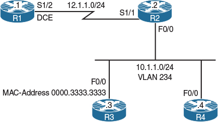
Figure 12-8 Configuring Match Destination and Source Address MAC
Figure 12-8 illustrates the topology that will be used in the following tasks.
Task 1
Configure RIPv2 on all routers and advertise their directly connected interface(s):
On All Routers:
Rx(config)# router rip
Rx(config-router)# no auto-summary
Rx(config-router)# version 2
Rx(config-router)# network 0.0.0.0
Let’s verify the configuration:
On R4:
R4# Show ip route rip | begin Gate
Gateway of last resort is not set
12.0.0.0/24 is subnetted, 1 subnets
R 12.1.1.0 [120/1] via 10.1.1.2, 00:00:07, FastEthernet0/1
Task 2
Configure R2 to classify and mark all IP routed traffic from any source destined to the MAC address of R3’s F0/0 interface with an IP-Precedence level of 1.
R2 is configured to match any packet destined to the MAC address of 0000.3333.3333, which is R3’s configured MAC address:
On R2:
R2(config)# class-map QOS
R2(config-cmap)# match destination-address mac 0000.3333.3333
R2(config)# policy-map TST
R2(config-pmap)# class QOS
R2(config-pmap-c)# set ip precedence 1
R2(config-pmap-c)# interface FastEthernet0/0
R2(config-if)# service-policy out TST
Note If destination-address Mac is configured in the class map, the policy map cannot be applied inbound because the logic will be incorrect; it must be applied outbound, meaning out toward the MAC address of R3.
Let’s verify the configuration:
On R2:
R2# show policy-map TST
Policy Map TST
Class QOS
set ip precedence 1
R2# show policy-map interface | section QOS
Class-map: QOS (match-all)
0 packets, 0 bytes
5 minute offered rate 0 bps, drop rate 0 bps
Match: destination-address mac 0000.3333.3333
QOS Set
precedence 1
Packets marked 0
On R3:
R3(config)# access-list 100 permit ip any any precedence 1 log
R3(config)# access-list 100 permit udp any any eq 520
R3(config)# interface FastEthernet0/0
R3(config-if)# ip access-group 100 in
On R1:
R1# ping 10.1.1.3 rep 10
Type escape sequence to abort.
Sending 10, 100-byte ICMP Echos to 10.1.1.3, timeout is 2 seconds:
!!!!!!!!!!
Success rate is 100 percent (10/10), round-trip min/avg/max = 1/2/4 ms
The preceding configures an access list with the log option to match on packets that are marked with an IP-Precedence level of 1. RIP also has been allowed.
Note The output of the following show command indicates that 10 packets were marked with an IP-Precedence value of 1:
R2# show policy-map interface
FastEthernet0/0
Service-policy output: TST
Class-map: QOS (match-all)
10 packets, 1140 bytes
5 minute offered rate 0 bps, drop rate 0 bps
Match: destination-address mac 0000.3333.3333
QOS Set
precedence 1
Packets marked 10
Class-map: class-default (match-any)
40 packets, 3931 bytes
5 minute offered rate 0 bps, drop rate 0 bps
Match: any
You can see that 10 packets matched the access list:
On R3:
R3# show access-list 100
Extended IP access list 100
10 permit ip any any precedence priority log (10 matches)
20 permit udp any any eq rip (2 matches)
Task 3
Configure R2 to classify and mark all IP-routed traffic from the MAC address of R3 to any destination with IP-Precedence level of 2.
On R2:
R2(config)# class-map Task4
R2(config-cmap)# match source-address mac 0000.3333.3333
R2(config)# policy-map QOS
R2(config-pmap)# class Task4
R2(config-pmap-c)# set ip precedence 2
R2(config-pmap-c)# interface FastEthernet0/0
R2(config-if)# service-policy in QOS
On R2:
R2# clear counters
Clear "show interface" counters on all interfaces [confirm]
Press Enter to confirm
On R3:
R3# ping 12.1.1.1 rep 100
Type escape sequence to abort.
Sending 100, 100-byte ICMP Echos to 12.1.1.1, timeout is 2 seconds:
!!!!!!!!!!!!!!!!!!!!!!!!!!!!!!!!!!!!!!!!!!!!!!!!!!!!!!!!!!!!!!!!!!!!!!
!!!!!!!!!!!!!!!!!!!!!!!!!!!!!!
Success rate is 100 percent (100/100), round-trip min/avg/max = 1/2/4 ms
Let’s verify the configuration:
On R2:
R2# show policy-map interface | section Task4
Class-map: Task4 (match-all)
100 packets, 11400 bytes
5 minute offered rate 0 bps, drop rate 0 bps
Match: source-address mac 0000.3333.3333
QOS Set
precedence 2
Packets marked 100
You can see that 100 packets were marked with an IP-Precedence value of 2.
Erase the startup configuration on the routers and reload them before proceeding to the next task.
Lab 12-8: Match IP DSCP/Precedence vs. Match DSCP
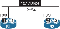
Figure 12-9 Configuring Match IP DSCP/Precedence vs. Match DSCP
Figure 12-9 illustrates the topology that will be used in the following tasks.
Task 1
R1’s F0/0 interface should be configured such that it can verify the IP-Precedence marking of incoming traffic. Use R2 to generate traffic with an IP-Precedence value of 1. Do not use an MQC or an access list to accomplish this task.
For verification, eight class maps are configured on R1, each matching different IP-Precedence levels. Also, a policy map called “TST” is configured to reference the eight class maps, and the policy map “TST” is applied to the F0/0 interface of R1 in the inbound direction.
On R1:
R1(config)# class-map P0
R1(config-cmap)# match ip precedence 0
R1(config)# class-map P1
R1(config-cmap)# match ip precedence 1
R1(config)# class-map P2
R1(config-cmap)# match ip precedence 2
R1(config)# class-map P3
R1(config-cmap)# match ip precedence 3
R1(config)# class-map P4
R1(config-cmap)# match ip precedence 4
R1(config)# class-map P5
R1(config-cmap)# match ip precedence 5
R1(config)# class-map P6
R1(config-cmap)# match ip precedence 6
R1(config)# class-map P7
R1(config-cmap)# match ip precedence 7
R1(config)# policy-map TST
R1(config-pmap)# class P0
R1(config-pmap)# class P1
R1(config-pmap)# class P2
R1(config-pmap)# class P3
R1(config-pmap)# class P4
R1(config-pmap)# class P5
R1(config-pmap)# class P6
R1(config-pmap)# class P7
R1(config)# interface FastEthernet0/0
R1(config-if)# service-policy input TST
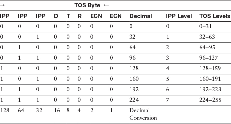
An extended ping can be used to generate traffic with different IP-Precedence levels. Remember that IP-Precedence uses the three most significant bits of the TOS byte. The decimal values of these bits are 128 (the most significant), 64 (the second most significant), and 32 (the third most significant). Table 12-1 identifies the TOS byte values and their corresponding IP-Precedence values.
On R2:
R2# ping
Protocol [ip]: →
Target IP address: 12.1.1.1
Repeat count [5]: →
Datagram size [100]: →
Timeout in seconds [2]: →
Extended commands [n]: y
Source address or interface: 12.1.1.2
Type of service [0]: 32
Set DF bit in IP header? [no]: →
Validate reply data? [no]: →
Data pattern [0xABCD]: →
Loose, Strict, Record, Timestamp, Verbose[none]: →
Sweep range of sizes [n]: →
Type escape sequence to abort.
Sending 5, 100-byte ICMP Echos to 10.1.12.1, timeout is 2 seconds:
Packet sent with a source address of 10.1.12.2
!!!!!
Success rate is 100 percent (5/5), round-trip min/avg/max = 1/2/4 ms
On R1:
R1# show policy-map interface | section P1
Class-map: P1 (match-all)
5 packets, 570 bytes
5 minute offered rate 0 bps
Match: ip precedence 1
Note The output of the preceding show command reveals that five packets were matched to IP-Precedence level 1.
Based on table 12-1, if R2 pings R1 using a TOS value of 32 to 63, the result will be the same, meaning that the traffic will be generated with an IP-Precedence value of 1. Let’s test this:
On R2:
R2# ping
Protocol [ip]: →
Target IP address: 12.1.1.1
Repeat count [5]: →
Datagram size [100]: →
Timeout in seconds [2]: →
Extended commands [n]: y
Source address or interface: 12.1.1.2
Type of service [0]: 63
Set DF bit in IP header? [no]: →
Validate reply data? [no]: →
Data pattern [0xABCD]: →
Loose, Strict, Record, Timestamp, Verbose[none]: →
Sweep range of sizes [n]: →
Type escape sequence to abort.
Sending 5, 100-byte ICMP Echos to 10.1.12.1, timeout is 2 seconds:
Packet sent with a source address of 10.1.12.2
!!!!!
Success rate is 100 percent (5/5), round-trip min/avg/max = 1/2/4 ms
Now we can verify the configuration:
On R1:
R1# show policy-map interface | section P1
Class-map: P1 (match-all)
10 packets, 1140 bytes
5 minute offered rate 0 bps
Match: ip precedence 1
Let’s test the same scenario using IPv6:
On R1:
R1# clear counters
Clear "show interface" counters on all interfaces [confirm]
Press Enter to confirm
On R2:
R2# ping ipv6
Target IPv6 address: 12::1
Repeat count [5]: →
Datagram size [100]: →
Timeout in seconds [2]: →
Extended commands? [no]: Y
Source address or interface: 12::2
UDP protocol? [no]: →
Verbose? [no]: →
Precedence [0]: 1
Include hop by hop option? [no]: →
Include destination option? [no]: →
Sweep range of sizes? [no]: →
Type escape sequence to abort.
Sending 5, 100-byte ICMP Echos to 12::1, timeout is 2 seconds:
Packet sent with a source address of 12::2
!!!!!
Success rate is 100 percent (5/5), round-trip min/avg/max = 0/1/4 ms
Now let’s verify the configuration:
On R1:
R1# show policy-map interface | section P1
Class-map: P1 (match-all)
0 packets, 0 bytes
5 minute offered rate 0 bps
Match: ip precedence 1
Note: IPv6 traffic was not matched to class P1.
Task 2
Remove the service policy, policy map, and class map from R1 configured in the previous task:
On R1:
R1(config)# interface FastEthernet0/0
R1(config-if)# no service-policy input TST
R1(config)# no policy-map TST
R1(config)# no class-map P0
R1(config)# no class-map P1
R1(config)# no class-map P2
R1(config)# no class-map P3
R1(config)# no class-map P4
R1(config)# no class-map P5
R1(config)# no class-map P6
R1(config)# no class-map P7
Task 3
R2 should ping R1’s F0/0 IPv6 address (12::1); this traffic should be generated with a DSCP value of 20. You should use an MQC to verify the traffic’s DSCP marking only for IPv6 packets on R1.
Because the DSCP value of IPv6 traffic must be matched, the match statement in the class map includes two statements: match dscp and match protocol ipv6.
On R1:
R1(config)# class-map D20
R1(config-cmap)# match protocol ipv6
R1(config-cmap)# match dscp 20
R1(config)# policy-map TST
R1(config-pmap)# class D20
R1(config-pmap)# interface FastEthernet0/0
R1(config-if)# service-policy in TST
Let’s test the configuration:
On R2:
R2(config)# policy-map tst
R2(config-pmap)# class class-default
R2(config-pmap-c)# set dscp 20
R2(config-pmap-c)# interface FastEthernet0/0
R2(config-if)# service-policy output tst
R2# ping ipv6 12::1 repeat 100
Type escape sequence to abort.
Sending 100, 100-byte ICMP Echos to 12::1, timeout is 2 seconds:
!!!!!!!!!!!!!!!!!!!!!!!!!!!!!!!!!!!!!!!!!!!!!!!!!!!!!!!!!!!!!!!!!!!!!!
!!!!!!!!!!!!!!!!!!!!!!!!!!!!!!
Success rate is 100 percent (100/100), round-trip min/avg/max = 0/0/0 ms
Now let’s verify the configuration:
On R1:
R1# show policy-map interface | section D20
Class-map: D20 (match-all)
103 packets, 11642 bytes
5 minute offered rate 0 bps
Match: protocol ipv6
Match: dscp af22 (20)
You can see that the DSCP value was matched in the IPv6 packets. Let’s ping R1’s IP address to see if it matches the D20 class map:
On R1:
R1# clear counters
Clear "show interface" counters on all interfaces [confirm]
Press Enter to confirm
On R2:
R2# ping 12.1.1.1 repeat 100
Type escape sequence to abort.
Sending 100, 100-byte ICMP Echos to 10.1.12.1, timeout is 2 seconds:
!!!!!!!!!!!!!!!!!!!!!!!!!!!!!!!!!!!!!!!!!!!!!!!!!!!!!!!!!!!!!!!!!!!!!!
!!!!!!!!!!!!!!!!!!!!!!!!!!!!!!
Success rate is 100 percent (100/100), round-trip min/avg/max = 1/1/4 ms
Let’s verify the test:
On R1:
R1# show policy-map interface
FastEthernet0/0
Service-policy input: TST
Class-map: D20 (match-all)
0 packets, 0 bytes
5 minute offered rate 0 bps
Match: protocol ipv6
Match: dscp af22 (20)
Class-map: class-default (match-any)
100 packets, 11400 bytes
5 minute offered rate 0 bps, drop rate 0 bps
Match: any
You can see that if match ip dscp or match ip precedence is used, the match is based on IPv4 traffic, whereas match dscp or match precedence can match on IPv4 or IPv6. If the match statement must match the marking on the IPv6 traffic only, then a route map should be configured with two match statements: one to match the IPv6 protocol using match protocol ipv6, and the second to match on the actual DSCP value using match dscp.
Erase the startup configuration on the routers and reload them before proceeding to the next task.
Lab 12-9: Match Protocol HTTP URL, MIME, and Host
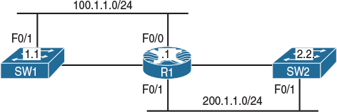
Figure 12-10 Configuring Match Protocol HTTP URL, MIME, and Host
Figure 12-10 illustrates the topology that will be used in the following tasks.
Task 1
Save the configuration of SW1 and copy the startup configuration of this switch (config.text) to compact flash as config.mpeg, config.jpeg, and config.txt.
On SW1:
SW1# write
SW1# dir
Directory of flash:/
2 -rwx 7899301 Mar 1 1993 00:19:35 +00:00 c3560-advipservicesk9-mz.122-25.SEE.bin
3 -rwx 1320 Mar 1 1993 00:11:17 +00:00 config.text
4 -rwx 24 Mar 1 1993 00:11:17 +00:00 private-config.text
SW1# copy config.text config.mpeg
Destination filename [config.mpeg]? → Press Enter
SW1# copy config.text config.txt
Destination filename [config.txt]? → Press Enter
SW1# copy config.text config.jpeg
Destination filename [config.jpeg]? → Press Enter
Let’s verify the configuration:
On SW1:
Switch# dir
Directory of flash:/
2 -rwx 7899301 Mar 1 1993 00:19:35 +00:00 c3560-advipservicesk9-mz.122-25.SEE.bin
3 -rwx 1320 Mar 1 1993 00:11:17 +00:00 config.text
4 -rwx 24 Mar 1 1993 00:11:17 +00:00 private-config.text
5 -rwx 1320 Mar 1 1993 00:13:35 +00:00 config.mpeg
6 -rwx 1320 Mar 1 1993 00:13:44 +00:00 config.txt
7 -rwx 1320 Mar 1 1993 00:13:55 +00:00 config.jpeg
15998976 bytes total (8091648 bytes free)
Task 2
Enable the Cisco web browser interface on SW1 and set the HTTP path used to locate the files created in the previous step:
On SW1:
SW1(config)# ip http server
SW1(config)# ip http path flash:
Let’s verify the configuration:
On SW1:
SW1# show ip http server status
HTTP server status: Enabled
HTTP server port: 80
HTTP server authentication method: enable
HTTP server access class: 0
HTTP server base path: flash:
Maximum number of concurrent server connections allowed: 16
(The rest of the output is omitted)
Task 3
Configure R1’s F0/1 interface such that it blocks any URL that contains any file type with an extension of “.mpeg”:
On R1:
R1(config)# class-map QOS
R1(config-cmap)# match protocol http url *.mpeg
R1(config)# policy-map TST
R1(config-pmap)# class QOS
R1(config-pmap-c)# drop
R1(config-pmap-c)# interface FastEthernet0/1
R1(config-if)# service-policy input TST
Let’s verify the configuration:
On R1:
R1# show class-map QOS
Class Map match-all QOS (id 1)
Match protocol http url "*.mpeg"
R1# show policy-map TST
Policy Map TST
Class QOS
drop
R1# show policy-map interface FastEthernet0/1
FastEthernet0/1
Service-policy input: TST
Class-map: QOS (match-all)
0 packets, 0 bytes
5 minute offered rate 0 bps, drop rate 0 bps
Match: protocol http url "*.mpeg"
drop
Class-map: class-default (match-any)
0 packets, 0 bytes
5 minute offered rate 0 bps, drop rate 0 bps
Match: any
For testing purposes, config.txt is copied first; you should be able to copy this file successfully:
On SW2:
SW2# copy http://100.1.1.11/config.txt Null:
Loading http://100.1.1.11/config.txt !
1711 bytes copied in 0.026 secs (65808 bytes/sec)
Note The file size on your switch may be different.
The following operation fails because of the “.mpeg” extension, which is blocked on R1:
SW2# copy http://100.1.1.11/config.mpeg NULL:
%Error opening http://100.1.1.11/config.mpeg (I/O error)
Task 4
Reconfigure R1 such that it blocks any URL that contains any file type with an extension of “.mpeg” or “.jpeg”:
On R1:
R1(config)# class-map QOS
R1(config-cmap)# no match protocol http url *.mpeg
R1(config-cmap)# match protocol http url *.mpeg|*.jpeg
Let’s verify the configuration:
On R1:
R1# show class-map QOS
Class Map match-all QOS (id 1)
Match protocol http url "*.mpeg|*.jpeg"
R1# show policy-map interface FastEthernet0/1
FastEthernet0/1
Service-policy input: TST
Class-map: QOS (match-all)
8 packets, 1320 bytes
5 minute offered rate 0 bps, drop rate 0 bps
Match: protocol http url "*.mpeg|*.jpeg"
drop
Class-map: class-default (match-any)
18 packets, 1481 bytes
5 minute offered rate 0 bps, drop rate 0 bps
Match: any
Let’s test the configuration:
On SW2:
SW2# copy http://100.1.1.11/config.mpeg NULL:
Note These two copy operations fail because the file extensions are blocked on R1.
You should receive the following console message:
%Error opening http://100.1.1.11/config.mpeg (I/O error)
SW2# copy http://100.1.1.11/config.jpeg NULL:
You should receive the following console message:
%Error opening http://100.1.1.11/config.jpeg (I/O error)
Note The following copy operation is successful because the “.txt” extension is not blocked by R1:
SW2# copy http://100.1.1.11/config.txt NULL:
Loading http://100.1.1.11/config.txt !
1711 bytes copied in 0.017 secs (100647 bytes/sec)
Task 5
Reconfigure R1 such that any HTTP call to the server located at 100.1.1.11 is dropped:
On R1:
R1(config-if)# class-map QOS
R1(config-cmap)# no match protocol http url *.mpeg|*.jpeg
R1(config-cmap)# match protocol http host 100.1.1.11
On SW2:
SW2# copy http://100.1.1.11/config.txt NULL:
You should see the following console message:
%Error opening http://12.1.1.10/config.txt (I/O error)
SW2# copy http://12.1.1.10/config.mpeg NULL:
You should also see this console message:
%Error opening http://12.1.1.10/config.mpeg (I/O error)
SW2# copy http://12.1.1.10/config.jpeg NULL:
You should see the following console message as well:
%Error opening http://12.1.1.10/config.jpeg (I/O error)
Erase the startup configuration on the routers and reload them before proceeding to the next task.
Lab 12-10: Class-Based Policing
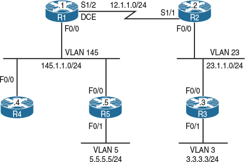
Figure 12-11 Configuring a Match Based on DSCP Values
Figure 12-11 illustrates the topology that will be used in the following tasks.
Task 1
Configure R1’s S1/2 interface using the following policy:
![]() ICMP traffic should be rate-limited to 10 Kbps outbound.
ICMP traffic should be rate-limited to 10 Kbps outbound.
![]() Traffic conforming to this threshold should be marked with a DSCP value of 30 and transmitted, and traffic exceeding this threshold should be marked with a DSCP value of 10 and transmitted.
Traffic conforming to this threshold should be marked with a DSCP value of 30 and transmitted, and traffic exceeding this threshold should be marked with a DSCP value of 10 and transmitted.
Because access lists cannot be used, using Network Based Application Recognition is probably the only way to identify these traffic types. With NBAR, you must have “IP CEF” enabled. All the new IOS releases have CEF enabled on most of the platforms.
When you’re configuring class-based policing, if the Bc value is not specified, it will default to CIR / 32 or 1500 bytes, whichever is the higher value. Remember that in a single-rate single bucket, Be is disabled, and if it is configured, the system will ignore it. The Be rate can only be utilized when a violate action is configured.
Note To configure a match for the specified protocols, NBAR is used. NBAR uses the match protocol command to match on different protocols. When the first match command is entered, there will be a slight delay before the cursor is available again, but the subsequent match statements will not have this behavior. This happens because when NBAR is used for the first time, it needs to download and decompress the Packet Description Language Modules (PDLM) from the Flash memory into the main memory. Once they are loaded and decompressed, they can be used and accessed very quickly.
On R1:
R1(config)# class-map ICMP
Note Because neither match-any or match-all is configured, the match-all option is the default:
R1(config-cmap)# match protocol icmp
R1(config)# policy-map tst
R1(config-pmap)# class ICMP
R1(config-pmap-c)# police 10000 conform-act set-dscp-tra 30 exceed-act set-dscp-tran 10
Note When configuring the rate-limit interface command, you must configure the normal burst and maximum burst. When configuring the police command through the MQC, you do not have to configure these values. If they are not configured, the system will use the CIR / 32 or 1500 bytes, whichever one is higher, as the normal burst. Also, the conform-action will be to transmit, and the exceed-action will be automatically set to drop.
R1(config-pmap-c)# interface serial1/2
R1(config-if)# service-policy output tst
Let’s verify the configuration:
On R1:
R1# show policy-map interface serial1/2
Serial1/2
Service-policy output: tst
Class-map: ICMP (match-all)
0 packets, 0 bytes
5 minute offered rate 0 bps, drop rate 0 bps
Match: protocol icmp
police:
cir 10000 bps, bc 1500 bytes
conformed 0 packets, 0 bytes; actions:
set-dscp-transmit af33
exceeded 0 packets, 0 bytes; actions:
set-dscp-transmit af11
conformed 0 bps, exceed 0 bps
Class-map: class-default (match-any)
5 packets, 428 bytes
5 minute offered rate 0 bps, drop rate 0 bps
Match: any
To test this configuration, R2 is configured to match on DSCP values of 30 and 10:
On R2:
R2(config)# class-map d30
R2(config-cmap)# match ip dscp 30
R2(config)# class-map d10
R2(config-cmap)# match ip dscp 10
R2(config)# policy-map tst
R2(config-pmap)# class d30
R2(config-pmap)# class d10
R2(config)# interface serial1/1
R2(config-if)# service-policy input tst
Let’s set the load-interval to 30 seconds, which is the minimum value. If this is not set to 30 seconds, the load calculation will be performed every 5 minutes:
R2(config)# interface serial1/1
R2(config-if)# load-interval 30
Let’s ping R2 from R1 with a high repeat count and verify the output on R2:
R1# ping 12.1.1.2 rep 9999999
Type escape sequence to abort.
Sending 9999999, 100-byte ICMP Echos to 12.1.1.2, timeout is 2 seconds:
!!!!!!!!!!!!!!!!!!!!!!!!!!!!!!!!!!!!!!!!!!!!!!!!!!!!!!!!!!!!!!!!!!!!!!
Now, while the ICMP packets are running, let’s verify the output on R2:
R2# show policy-map interface
Serial1/1
Service-policy input: tst
Class-map: d30 (match-all)
471 packets, 48984 bytes
30 second offered rate 8000 bps
Match: ip dscp af33 (30)
Class-map: d10 (match-all)
1726 packets, 179504 bytes
30 second offered rate 26000 bps
Match: ip dscp af11 (10)
Class-map: class-default (match-any)
0 packets, 0 bytes
30 second offered rate 0 bps, drop rate 0 bps
Match: any
R2# show policy-map interface
Serial1/1
Service-policy input: tst
Class-map: d30 (match-all)
1095 packets, 113880 bytes
30 second offered rate 9000 bps
Match: ip dscp af33 (30)
Class-map: d10 (match-all)
4104 packets, 426816 bytes
30 second offered rate 38000 bps
Match: ip dscp af11 (10)
Class-map: class-default (match-any)
0 packets, 0 bytes
30 second offered rate 0 bps, drop rate 0 bps
Match: any
R2# show policy-map interface
Serial1/1
Service-policy input: tst
Class-map: d30 (match-all)
1711 packets, 177944 bytes
30 second offered rate 10000 bps
Match: ip dscp af33 (30)
Class-map: d10 (match-all)
6451 packets, 670904 bytes
30 second offered rate 38000 bps
Match: ip dscp af11 (10)
Class-map: class-default (match-any)
0 packets, 0 bytes
30 second offered rate 0 bps, drop rate 0 bps
Match: any
You can see that the rate remains around 10,000 Kbps.
Task 2
Configure R2’s F0/0 interface using the following policy:
![]() The outgoing Telnet traffic should be rate-limited to 10 Mbps. This traffic should be configured with a minimum amount of normal burst.
The outgoing Telnet traffic should be rate-limited to 10 Mbps. This traffic should be configured with a minimum amount of normal burst.
![]() The outgoing TFTP traffic should be limited to 8 Mbps, with 40,000 bps of normal bursts.
The outgoing TFTP traffic should be limited to 8 Mbps, with 40,000 bps of normal bursts.
![]() Both Telnet and TFTP traffic exceeding this policy should be dropped; if they conform to this policy, they should be transmitted.
Both Telnet and TFTP traffic exceeding this policy should be dropped; if they conform to this policy, they should be transmitted.
![]() Do not create an access list to accomplish this task.
Do not create an access list to accomplish this task.
On R2:
R2(config)# class-map TELNET
R2(config-cmap)# match protocol telnet
R2(config)# class-map TFTP
R2(config-cmap)# match protocol tftp
R2(config)# policy-map TST
R2(config-pmap)# class TELNET
R2(config-pmap-c)# police 10000000 1000 conform-ac trans exceed-ac drop
You should receive the following console message telling you that the minimum normal burst size for a CIR of 10 Mbps should be 5000 bytes, so the system sets the normal burst to 5000:Conform burst size increased to 5000.
IOS looks at the configured CIR and uses the following formula: CIR/32 or 1500, or whichever one is higher. IOS will not allow a Bc size lower than 5000 for a CIR of 10 Mbps.
R2(config-pmap)# class TFTP
R2(config-pmap-c)# police 8000000 5000 conform-ac trans exceed-ac drop
R2(config-pmap-c-police)# interface FastEthernet0/0
R2(config-if)# service-policy out TST
Let’s verify the configuration:
On R2:
R2# show policy-map interface FastEthernet0/0
FastEthernet0/0
Service-policy output: TST
Class-map: TELNET (match-all)
0 packets, 0 bytes
5 minute offered rate 0 bps, drop rate 0 bps
Match: protocol telnet
police:
cir 10000000 bps, bc 5000 bytes
conformed 0 packets, 0 bytes; actions:
transmit
exceeded 0 packets, 0 bytes; actions:
drop
conformed 0 bps, exceed 0 bps
Class-map: TFTP (match-all)
0 packets, 0 bytes
5 minute offered rate 0 bps, drop rate 0 bps
Match: protocol tftp
police:
cir 8000000 bps, bc 5000 bytes
conformed 0 packets, 0 bytes; actions:
transmit
exceeded 0 packets, 0 bytes; actions:
drop
conformed 0 bps, exceed 0 bps
Class-map: class-default (match-any)
7 packets, 721 bytes
5 minute offered rate 0 bps, drop rate 0 bps
Match: any
The last entry (Class-map class-default) is always created automatically by the system. It is the catchall condition. Basically, any traffic that was not specified will use the class class-default.
Task 3
R1 has two hosts (R4 and R5) connected to its F0/0 interface with the following MAC addresses:
![]() R4: 0000.4444.4444
R4: 0000.4444.4444
![]() R5: 0000.5555.5555
R5: 0000.5555.5555
The traffic with a source MAC address of 0000.4444.4444 should be policed to 10 Kbps inbound, whereas the traffic with a source MAC address of 0000.5555.5555 should be policed to 20 Kbps inbound. Traffic from these hosts should only be processed if they conform to this policy. Do not use match source-address to accomplish this task.
The task states that the match source-address mac command cannot be used; because of this restriction, two MAC address access lists should be configured: one identifying R4’s MAC address and the other identifying R5’s MAC address as follows:
Note You may have to use Ctrl+Shift+6 to stop the pings on R1 before continuing with the configuration of this task.
On R1:
R1(config)# access-list 700 permit 0000.4444.4444
R1(config)# class-map R4
R1(config-cmap)# match access-group 700
R1(config)# access-list 701 permit 0000.5555.5555
R1(config)# class-map R5
R1(config-cmap)# match access-group 701
R1(config)# policy-map TEST
R1(config-pmap)# class R4
R1(config-pmap-c)# police 10000 conform-ac trans exceed-ac drop
R1(config-pmap)# class R5
R1(config-pmap-c)# police 20000 conform-ac trans exceed-ac drop
R1(config)# interface FastEthernet0/0
R1(config-if)# service-policy in TEST
Let’s verify the configuration:
On R1:
R1# Show policy-map interface FastEthernet0/0
FastEthernet0/0
Service-policy input: TEST
Class-map: R4 (match-all)
0 packets, 0 bytes
5 minute offered rate 0 bps, drop rate 0 bps
Match: access-group 700
police:
cir 10000 bps, bc 1500 bytes
conformed 0 packets, 0 bytes; actions:
transmit
exceeded 0 packets, 0 bytes; actions:
drop
conformed 0 bps, exceed 0 bps
Class-map: R5 (match-all)
0 packets, 0 bytes
5 minute offered rate 0 bps, drop rate 0 bps
Match: access-group 701
police:
cir 20000 bps, bc 1500 bytes
conformed 0 packets, 0 bytes; actions:
transmit
exceeded 0 packets, 0 bytes; actions:
drop
conformed 0 bps, exceed 0 bps
Class-map: class-default (match-any)
0 packets, 0 bytes
5 minute offered rate 0 bps, drop rate 0 bps
Match: any
Task 4
Ensure that HTTP, FTP, and ICMP traffic on R3’s F0/1 interface is policed to 10 Mbps on weekdays from 11:00 a.m. to 3:00 p.m. Traffic exceeding this policy should be dropped, and traffic conforming to this policy should be transmitted.
On R3:
R3(config)# time-range weekdays
R3(config-time-range)# periodic weekdays 11:00 to 15:00
R3(config)# access-list 100 permit tcp any any eq www time-range weekdays
R3(config)# access-list 100 permit icmp any any time-range weekdays
R3(config)# access-list 100 permit tcp any any eq 20 time-range weekdays
R3(config)# access-list 100 permit tcp any any eq 21 time-range weekdays
R3(config)# class-map QOS
R3(config-cmap)# match access-group 100
R3(config)# policy-map Task5
R3(config-pmap)# class QOS
R3(config-pmap-c)# police 10000000 conform-act trans exceed-act drop
R3(config-pmap-c)# interface FastEthernet0/0
R3(config-if)# service-policy out Task5
Let’s verify the configuration:
On R3:
R3# Show policy-map interface FastEthernet0/1
FastEthernet0/1
Service-policy output: Task5
Class-map: QOS (match-all)
0 packets, 0 bytes
5 minute offered rate 0 bps, drop rate 0 bps
Match: access-group 100
police:
cir 10000000 bps, bc 312500 bytes
conformed 0 packets, 0 bytes; actions:
transmit
exceeded 0 packets, 0 bytes; actions:
drop
conformed 0 bps, exceed 0 bps
Class-map: class-default (match-any)
8 packets, 781 bytes
5 minute offered rate 0 bps, drop rate 0 bps
Match: any
Erase the startup configuration and reload the routers before proceeding to the next lab.
Lab 12-11: Class-Based Shaping
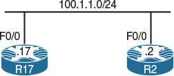
Figure 12-12 Configuring Class-Based Shaping
Figure 12-12 illustrates the topology that will be used in the following tasks.
Task 1
Traffic from R17 to R2 should be shaped to 16,000 bps. R17 should be configured to send a Bc worth of data every Tc. Configure Tc to be 4 seconds; R17 should send 8000 bytes per Tc.
Traffic can be rate-limited in two ways: You can rate-limit traffic with buffering capabilities, in which case it’s called shaping, or you can rate-limit traffic without any buffering capabilities, which is called policing.
In traffic shaping, you have two choices: shape average and shape peak. When you send a Bc worth of data every Tc, you are performing a shape average, but if you send Bc + Be every Tc, you are performing a shape peak.
The task states that R17 should send a Bc worth of data every Tc, which means that a shape average should be configured. Because R17 should be configured to send 8000 bytes per Tc, this means that the Bc value should be set to 8 × 8000 = 64,000.
Although task doesn’t specify the Be value, it must be configured as zero. If the Be value is not configured at all (not even as zero), Be will equal to Bc.
On R17:
R17(config)# policy-map tst
R17(config-pmap)# class class-default
R17(config-pmap-c)# shape average 16000 64000 0
R17(config)# interface FastEthernet0/0
R17(config-if)# service-policy out tst
Let’s verify the configuration:
On R17:
R17# show policy-map interface
FastEthernet0/0
Service-policy output: tst
Class-map: class-default (match-any)
8 packets, 773 bytes
5 minute offered rate 0 bps, drop rate 0 bps
Match: any
Traffic Shaping
Target/Average Byte Sustain Excess Interval Increment
Rate Limit bits/int bits/int (ms) (bytes)
16000/16000 8000 64000 0 4000 8000
Adapt Queue Packets Bytes Packets Bytes Shaping
Active Depth Delayed Delayed Active
- 0 8 773 0 0 no
Based on the shaping parameters configured, if Bc is divided by the CIR, it should give us the Tc value, which in this case is 64,000 / 16,000 = 4 seconds.
Therefore, every 4 seconds, R17 will be sending a Bc worth of data because a shape average is configured.
So, every 4 seconds R17 will send 64,000 bps. Because we are going to test this using a ping command, and the size of the packets in ping is defined in bytes, let’s divide 64,000 by 8, which will give us 8000 bytes (the amount of data that R17 will send every 4 seconds). Let’s configure and test:
On R17:
R17# Debug ip icmp
ICMP packet debugging is on
R17(config)# line con 0
R17(config-line)# logging synchronous
R17# ping 100.1.1.2 size 1000 timeout 0 repeat 32
Type escape sequence to abort.
Sending 32, 1000-byte ICMP Echos to 100.1.1.2, timeout is 0 seconds:
................................
Success rate is 0 percent (0/32)
*Sep 27 21:29:34.743: ICMP: echo reply rcvd, src 100.1.1.2, dst 100.1.1.17
*Sep 27 21:29:34.743: ICMP: echo reply rcvd, src 100.1.1.2, dst 100.1.1.17
*Sep 27 21:29:34.743: ICMP: echo reply rcvd, src 100.1.1.2, dst 100.1.1.17
*Sep 27 21:29:34.743: ICMP: echo reply rcvd, src 100.1.1.2, dst 100.1.1.17
*Sep 27 21:29:34.743: ICMP: echo reply rcvd, src 100.1.1.2, dst 100.1.1.17
*Sep 27 21:29:34.743: ICMP: echo reply rcvd, src 100.1.1.2, dst 100.1.1.17
*Sep 27 21:29:34.743: ICMP: echo reply rcvd, src 100.1.1.2, dst 100.1.1.17
*Sep 27 21:29:34.743: ICMP: echo reply rcvd, src 100.1.1.2, dst 100.1.1.17
*Sep 27 21:29:38.739: ICMP: echo reply rcvd, src 100.1.1.2, dst 100.1.1.17
*Sep 27 21:29:38.739: ICMP: echo reply rcvd, src 100.1.1.2, dst 100.1.1.17
*Sep 27 21:29:38.739: ICMP: echo reply rcvd, src 100.1.1.2, dst 100.1.1.17
*Sep 27 21:29:38.739: ICMP: echo reply rcvd, src 100.1.1.2, dst 100.1.1.17
*Sep 27 21:29:38.739: ICMP: echo reply rcvd, src 100.1.1.2, dst 100.1.1.17
*Sep 27 21:29:38.743: ICMP: echo reply rcvd, src 100.1.1.2, dst 100.1.1.17
*Sep 27 21:29:38.743: ICMP: echo reply rcvd, src 100.1.1.2, dst 100.1.1.17
*Sep 27 21:29:38.743: ICMP: echo reply rcvd, src 100.1.1.2, dst 100.1.1.17
*Sep 27 21:29:42.739: ICMP: echo reply rcvd, src 100.1.1.2, dst 100.1.1.17
*Sep 27 21:29:42.739: ICMP: echo reply rcvd, src 100.1.1.2, dst 100.1.1.17
*Sep 27 21:29:42.739: ICMP: echo reply rcvd, src 100.1.1.2, dst 100.1.1.17
*Sep 27 21:29:42.739: ICMP: echo reply rcvd, src 100.1.1.2, dst 100.1.1.17
*Sep 27 21:29:42.739: ICMP: echo reply rcvd, src 100.1.1.2, dst 100.1.1.17
*Sep 27 21:29:42.743: ICMP: echo reply rcvd, src 100.1.1.2, dst 100.1.1.17
*Sep 27 21:29:42.743: ICMP: echo reply rcvd, src 100.1.1.2, dst 100.1.1.17
*Sep 27 21:29:42.743: ICMP: echo reply rcvd, src 100.1.1.2, dst 100.1.1.17
*Sep 27 21:29:46.739: ICMP: echo reply rcvd, src 100.1.1.2, dst 100.1.1.17
*Sep 27 21:29:46.739: ICMP: echo reply rcvd, src 100.1.1.2, dst 100.1.1.17
*Sep 27 21:29:46.739: ICMP: echo reply rcvd, src 100.1.1.2, dst 100.1.1.17
*Sep 27 21:29:46.739: ICMP: echo reply rcvd, src 100.1.1.2, dst 100.1.1.17
*Sep 27 21:29:46.739: ICMP: echo reply rcvd, src 100.1.1.2, dst 100.1.1.17
*Sep 27 21:29:46.743: ICMP: echo reply rcvd, src 100.1.1.2, dst 100.1.1.17
*Sep 27 21:29:46.743: ICMP: echo reply rcvd, src 100.1.1.2, dst 100.1.1.17
*Sep 27 21:29:46.743: ICMP: echo reply rcvd, src 100.1.1.2, dst 100.1.1.17
The ping command is sending 1000-byte packets. Because the shape average is configured to send 8000 bytes every Tc, which is 4 seconds, we can see that every 4 seconds the local router is sending eight 1000-byte packets.
Erase the startup configuration of the routers and reload them before proceeding to the next lab.