Chapter 15 MPLS and L3VPNs
Multiprotocol Label Switching (MPLS) is a label switching technology. With MPLS, instead of relying on IP addresses in the IP header to route packets, the router actually builds a label switching path, or LSP, for packets that require sustained forwarding treatment. This is also known as a forwarding equivalence class (FEC) and includes source destination IPs, IP precedents, and so on.
In the packet, we can switch based on the MPLS label that the packet carries, while the MPLS label itself is swapped along the way until the packet reaches the last MPLS router closest to the destination. Before the packet label switching can happen, the router needs to know what label to use, and that is through a label distribution protocol, or LDP.
A router allocates local labels to the route it has in its routing table; then it exchanges labels with its LDP neighbors to complete the label switching path. There’s actually a lot more detail that goes on underneath the protocols in how the labels are actually distributed. Because LDP is a fundamental component of MPLS, the first lab in our MPLS exploration starts with looking at LDP and its configuration.
In this chapter, we’re going to be looking at LDP, including the LDP label exchange and how it actually happens. Then we’re going to look deep into the packet of LDP and see what that looks like.
Lab 15-1: Label Distribution Protocol
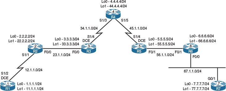
Figure 15-1 Configuring the Label Distribution Protocol
Task 1
Configure the topology shown in Figure 15-1. Do not configure any routing protocol. Use a VLAN ID of your choice.
On SW1:
SW1(config)# interface range FastEthernet0/2-3
SW1(config-if-range)# switchport mode access
SW1(config-if-range)# switchport access vlan 23
% Access VLAN does not exist. Creating vlan 23
SW1(config-if-range)# no shutdown
SW1(config)# interface range FastEthernet0/6-7
SW1(config-if-range)# switchport mode access
SW1(config-if-range)# switchport access vlan 67
% Access VLAN does not exist. Creating vlan 67
SW1(config-if-range)# no shutdown
On SW2:
SW2(config)# interface range FastEthernet0/5-6
SW2(config-if-range)# switchport mode access
SW2(config-if-range)# switchport access vlan 56
% Access VLAN does not exist. Creating vlan 56
SW2(config-if-range)# no shutdown
On R1:
R1(config)# interface loopback0
R1(config-if)# ip address 1.1.1.1 255.255.255.0
R1(config)# interface loopback1
R1(config-if)# ip address 11.1.1.1 255.255.255.0
R1(config)# interface serial1/2
R1(config-if)# clock rate 64000
R1(config-if)# ip address 12.1.1.1 255.255.255.0
R1(config-if)# no shutdown
On R2:
R2(config)# interface loopback0
R2(config-if)# ip address 2.2.2.2 255.255.255.0
R2(config)# interface loopback1
R2(config-if)# ip address 22.2.2.2 255.255.255.0
R2(config)# interface serial1/1
R2(config-if)# ip address 12.1.1.2 255.255.255.0
R2(config-if)# no shutdown
R2(config-if)# interface FastEthernet0/0
R2(config-if)# ip address 23.1.1.2 255.255.255.0
R2(config-if)# no shutdown
On R3:
R3(config)# interface loopback0
R3(config-if)# ip address 3.3.3.3 255.255.255.0
R3(config)# interface loopback1
R3(config-if)# ip address 33.3.3.3 255.255.255.0
R3(config)# interface FastEthernet0/0
R3(config-if)# ip address 23.1.1.3 255.255.255.0
R3(config-if)# no shutdown
R3(config)# interface serial1/4
R3(config-if)# clock rate 64000
R3(config-if)# ip address 34.1.1.3 255.255.255.0
R3(config-if)# no shutdown
On R4:
R4(config)# interface loopback0
R4(config-if)# ip address 4.4.4.4 255.255.255.0
R4(config)# interface loopback1
R4(config-if)# ip address 44.4.4.4 255.255.255.0
R4(config)# interface serial1/3
R4(config-if)# ip address 34.1.1.4 255.255.255.0
R4(config-if)# no shutdown
R4(config)# interface serial1/5
R4(config-if)# clock rate 64000
R4(config-if)# ip address 45.1.1.4 255.255.255.0
R4(config-if)# no shutdown
On R5:
R5(config)# interface loopback0
R5(config-if)# ip address 5.5.5.5 255.255.255.0
R5(config)# interface loopback1
R5(config-if)# ip address 55.5.5.5 255.255.255.0
R5(config)# interface serial1/4
R5(config-if)# ip address 45.1.1.5 255.255.255.0
R5(config-if)# no shutdown
R5(config)# interface FastEthernet0/1
R5(config-if)# ip address 56.1.1.5 255.255.255.0
R5(config-if)# no shutdown
On R6:
R6(config)# interface loopback0
R6(config-if)# ip address 6.6.6.6 255.255.255.0
R6(config)# interface loopback1
R6(config-if)# ip address 66.6.6.6 255.255.255.0
R6(config)# interface FastEthernet0/1
R6(config-if)# ip address 56.1.1.6 255.255.255.0
R6(config-if)# no shutdown
R6(config)# interface FastEthernet0/0
R6(config-if)# ip address 67.1.1.6 255.255.255.0
R6(config-if)# no shutdown
On R7:
R7(config)# interface loopback0
R7(config-if)# ip address 7.7.7.7 255.255.255.0
R7(config)# interface loopback1
R7(config-if)# ip address 77.7.7.7 255.255.255.0
R7(config)# interface GigabitEthernet0/0
R7(config-if)# ip address 67.1.1.7 255.255.255.0
R7(config-if)# no shutdown
Task 2
Configure OSPF Area 0 on all links in the topology shown in Figure 15-1, except loopback1 interfaces. Configure the OSPF router ID (RID) of these routers to be 0.0.0.x, where x is the router number. The loopback0 interface of R7 should be advertised with its correct mask.
On R1:
R1(config)# router ospf 1
R1(config-router)# router-id 0.0.0.1
R1(config-router)# network 12.1.1.1 0.0.0.0 area 0
R1(config-router)# network 1.1.1.1 0.0.0.0 area 0
On R2:
R2(config)# router ospf 1
R2(config-router)# router-id 0.0.0.2
R2(config-router)# network 12.1.1.2 0.0.0.0 area 0
R2(config-router)# network 2.2.2.2 0.0.0.0 area 0
R2(config-router)# network 23.1.1.2 0.0.0.0 area 0
You should see the following console message:
%OSPF-5-ADJCHG: Process 1, Nbr 0.0.0.1 on Serial1/1 from LOADING to FULL,
Loading Done
On R3:
R3(config)# router ospf 1
R3(config-router)# router-id 0.0.0.3
R3(config-router)# network 3.3.3.3 0.0.0.0 area 0
R3(config-router)# network 34.1.1.3 0.0.0.0 area 0
R3(config-router)# network 23.1.1.3 0.0.0.0 area 0
As adjacencies form we will see the system post notifications on the console.
%OSPF-5-ADJCHG: Process 1, Nbr 0.0.0.2 on FastEthernet0/0 from LOADING to FULL,
Loading Done
On R4:
R4(config)# router ospf 1
R4(config-router)# router-id 0.0.0.4
R4(config-router)# network 45.1.1.4 0.0.0.0 area 0
R4(config-router)# network 4.4.4.4 0.0.0.0 area 0
R4(config-router)# network 34.1.1.4 0.0.0.0 area 0
Again, console notifications will inform us as neighbor adjacencies come up.
%OSPF-5-ADJCHG: Process 1, Nbr 0.0.0.3 on Serial1/3 from LOADING to FULL,
Loading Done
On R5:
R5(config)# router ospf 1
R5(config-router)# router-id 0.0.0.5
R5(config-router)# network 5.5.5.5 0.0.0.0 area 0
R5(config-router)# network 56.1.1.5 0.0.0.0 area 0
R5(config-router)# network 45.1.1.5 0.0.0.0 area 0
You should see the following console message:
%OSPF-5-ADJCHG: Process 1, Nbr 0.0.0.4 on Serial1/4 from LOADING to FULL,
Loading Done
On R6:
R6(config)# router ospf 1
R6(config-router)# router-id 0.0.0.6
R6(config-router)# network 6.6.6.6 0.0.0.0 area 0
R6(config-router)# network 67.1.1.6 0.0.0.0 area 0
R6(config-router)# network 56.1.1.6 0.0.0.0 area 0
At this point an adjacency should form with the neighbor identified as 0.0.0.5.
%OSPF-5-ADJCHG: Process 1, Nbr 0.0.0.5 on FastEthernet0/1 from LOADING to FULL,
Loading Done
On R7:
R7(config)# interface loopback0
R7(config-if)# ip ospf net point-to-point
R7(config)# router ospf 1
R7(config-router)# router-id 0.0.0.7
R7(config-router)# network 67.1.1.7 0.0.0.0 area 0
R7(config-router)# network 7.7.7.7 0.0.0.0 area 0
We should see the last adjacency form.
%OSPF-5-ADJCHG: Process 1, Nbr 0.0.0.6 on GigabitEthernet0/0 from LOADING to
FULL, Loading Done
Let’s verify the configuration:
On R1:
R1# show ip route ospf | begin Gate
Gateway of last resort is not set
2.0.0.0/32 is subnetted, 1 subnets
O 2.2.2.2 [110/65] via 12.1.1.2, 00:00:59, Serial1/2
3.0.0.0/32 is subnetted, 1 subnets
O 3.3.3.3 [110/66] via 12.1.1.2, 00:00:10, Serial1/2
4.0.0.0/32 is subnetted, 1 subnets
O 4.4.4.4 [110/130] via 12.1.1.2, 00:00:10, Serial1/2
5.0.0.0/32 is subnetted, 1 subnets
O 5.5.5.5 [110/194] via 12.1.1.2, 00:00:10, Serial1/2
6.0.0.0/32 is subnetted, 1 subnets
O 6.6.6.6 [110/195] via 12.1.1.2, 00:00:10, Serial1/2
7.0.0.0/24 is subnetted, 1 subnets
O 7.7.7.0 [110/196] via 12.1.1.2, 00:00:10, Serial1/2
23.0.0.0/24 is subnetted, 1 subnets
O 23.1.1.0 [110/65] via 12.1.1.2, 00:00:20, Serial1/2
34.0.0.0/24 is subnetted, 1 subnets
O 34.1.1.0 [110/129] via 12.1.1.2, 00:00:10, Serial1/2
45.0.0.0/24 is subnetted, 1 subnets
O 45.1.1.0 [110/193] via 12.1.1.2, 00:00:10, Serial1/2
56.0.0.0/24 is subnetted, 1 subnets
O 56.1.1.0 [110/194] via 12.1.1.2, 00:00:10, Serial1/2
67.0.0.0/24 is subnetted, 1 subnets
O 67.1.1.0 [110/195] via 12.1.1.2, 00:00:10, Serial1/2
On R7:
R7# show ip route ospf | begin Gate
Gateway of last resort is not set
1.0.0.0/32 is subnetted, 1 subnets
O 1.1.1.1 [110/196] via 67.1.1.6, 00:00:05, GigabitEthernet0/0
2.0.0.0/32 is subnetted, 1 subnets
O 2.2.2.2 [110/132] via 67.1.1.6, 00:00:05, GigabitEthernet0/0
3.0.0.0/32 is subnetted, 1 subnets
O 3.3.3.3 [110/131] via 67.1.1.6, 00:00:05, GigabitEthernet0/0
4.0.0.0/32 is subnetted, 1 subnets
O 4.4.4.4 [110/67] via 67.1.1.6, 00:00:05, GigabitEthernet0/0
5.0.0.0/32 is subnetted, 1 subnets
O 5.5.5.5 [110/3] via 67.1.1.6, 00:00:05, GigabitEthernet0/0
6.0.0.0/32 is subnetted, 1 subnets
O 6.6.6.6 [110/2] via 67.1.1.6, 00:00:59, GigabitEthernet0/0
12.0.0.0/24 is subnetted, 1 subnets
O 12.1.1.0 [110/195] via 67.1.1.6, 00:00:05, GigabitEthernet0/0
23.0.0.0/24 is subnetted, 1 subnets
O 23.1.1.0 [110/131] via 67.1.1.6, 00:00:05, GigabitEthernet0/0
34.0.0.0/24 is subnetted, 1 subnets
O 34.1.1.0 [110/130] via 67.1.1.6, 00:00:05, GigabitEthernet0/0
45.0.0.0/24 is subnetted, 1 subnets
O 45.1.1.0 [110/66] via 67.1.1.6, 00:00:05, GigabitEthernet0/0
56.0.0.0/24 is subnetted, 1 subnets
O 56.1.1.0 [110/2] via 67.1.1.6, 00:00:59, GigabitEthernet0/0
Task 3
Configure the label distribution protocol on the links interconnecting the routers in this topology. Ensure that the LDP router ID (RID) is based on the IP address assigned to the loopback0 interfaces of these routers. You may override a command from the previous task to accomplish this task.
When configuring the label distribution protocol, you must specify the actual protocol that creates and distributes labels. This protocol can be either LDP or TDP; TDP is a Cisco proprietary tag distribution protocol that is obsolete. Therefore, this lab strictly focuses on LDP and not TDP.
The mpls label protocol command can be configured to specify the label distribution protocol. In IOS releases prior to 12.4, TDP was the default protocol used. The mpls label protocol ldp command should be configured in the global configuration mode to enable LDP.
Each label switch router (LSR) that is running LDP will be assigned a router ID. The mpls ldp router-id command can be used to set the router ID for a given LSR. The LDP RID defaults to similar rules as OSPF, EIGRP, and BGP, which means that if it is not configured statically, then the numerically highest IP address of any loopback interface is selected as the LDP RID. If a loopback interface does not exist, then the highest IP address configured on the router is chosen as the LDP RID.
It is a good practice to configure the LDP RID manually to ensure that the transport address of the MPLS peer is stable. Remember that LDP advertises its LDP RID as the transport address in the LDP discovery hello messages sent from the interface. Therefore, you must provide reachability for that router ID, where it must be an exact match with the LDP RID in the routing table.
The mpls ip command enables MPLS forwarding of IPv4 packets along the normally routed paths; in some documents, this is called dynamic label switching.
The following command configures LDP as the label distribution protocol:
On All routers:
Rx(config)# mpls label protocol ldp
The following command configures the LDP ID of the LSRs based on the IP address of the Lo0 interface:
Rx(config)# mpls ldp router-id loopback 0
Finally, enable the MPLS forwarding of IPv4 packets along the normal routed paths:
On R1:
R1(config)# interface Serial1/2
R1(config-if)# mpls ip
On R2:
R2(config)# interface Serial1/1
R2(config-if)# mpls ip
You should receive the following console message stating that the local router has discovered a neighbor—in this case, R1 (1.1.1.1):
%LDP-5-NBRCHG: LDP Neighbor 1.1.1.1:0 is UP
Note LDP uses a 6-byte quantity, and the first 4 bytes are the LDP router ID. The LDP router ID was specified earlier using the MPLS ldp router-id command, and the last 2 bytes (:0) identify the label space; for a platform-wide label space, the last 2 bytes are always set to 0.
We will continue the configuration by enabling MPLS on the physical interface of R2.
R2(config)# interface FastEthernet0/0
R2(config-if)# mpls ip
Let’s verify the configuration:
On R2:
R2# show mpls interfaces
Interface IP Tunnel BGP Static Operational
FastEthernet0/0 Yes (ldp) No No No Yes
Serial1/1 Yes (ldp) No No No Yes
Note The output of the preceding command reveals that LDP is running on the F0/0 and S1/1 interfaces of R2.
On R3:
R3(config)# interface Serial1/4
R3(config-if)# mpls ip
R3(config)# interface FastEthernet0/0
R3(config-if)# mpls ip
You should see the following console message:
%LDP-5-NBRCHG: LDP Neighbor 2.2.2.2:0 (1) is UP
Let’s verify the configuration:
On R3:
R3# show mpls interfaces
Interface IP Tunnel BGP Static Operational
FastEthernet0/0 Yes (ldp) No No No Yes
Serial1/4 Yes (ldp) No No No Yes
Let’s configure R4:
On R4:
R4(config)# interface Serial1/3
R4(config-if)# mpls ip
R4(config)# interface Serial1/5
R4(config-if)# mpls ip
You should see the following console message:
%LDP-5-NBRCHG: LDP Neighbor 3.3.3.3:0 (1) is UP
Let’s verify the configuration:
On R4:
R4# show mpls interfaces
Interface IP Tunnel BGP Static Operational
Serial1/3 Yes (ldp) No No No Yes
Serial1/5 Yes (ldp) No No No Yes
Let’s configure R5:
On R5:
R5(config)# interface FastEthernet0/1
R5(config-if)# mpls ip
R5(config)# interface Serial1/4
R5(config-if)# mpls ip
You should see the following console message:
%LDP-5-NBRCHG: LDP Neighbor 4.4.4.4:0 (1) is UP
Let’s verify the configuration:
On R5:
R5# show mpls interfaces
Interface IP Tunnel BGP Static Operational
FastEthernet0/1 Yes (ldp) No No No Yes
Serial1/4 Yes (ldp) No No No Yes
Let’s configure R6:
On R6:
R6(config)# interface FastEthernet0/1
R6(config-if)# mpls ip
R6(config)# interface FastEthernet0/0
R6(config-if)# mpls ip
You should see the following console message:
%LDP-5-NBRCHG: LDP Neighbor 5.5.5.5:0 (1) is UP
Let’s verify the configuration:
On R6:
R6# show mpls interface
Interface IP Tunnel BGP Static Operational
FastEthernet0/0 Yes (ldp) No No No Yes
FastEthernet0/1 Yes (ldp) No No No Yes
Let’s configure R7:
On R7:
R7(config)# interface GigabitEthernet0/0
R7(config-if)# mpls ip
You should see the following console message:
%LDP-5-NBRCHG: LDP Neighbor 6.6.6.6:0 (1) is UP
Let’s verify the configuration:
On R7:
R7# show mpls interfaces
Interface IP Tunnel BGP Static Operational
GigabitEthernet0/0 Yes (ldp) No No No Yes
Once the LSRs are configured, they will attempt to discover neighbors. This discovery uses hello messages. The hello messages are UDP packets sent to a destination multicast address of 224.0.0.2, with a source and destination port of 646. Every hello message has a hold timer; by default, the hello messages are sent every 5 seconds, and the hold timer is set to 15 seconds.
Let’s view the discover messages:
On R1:
R1# show access-list
R1(config)# access-list 100 permit udp host 12.1.1.1 eq 646 any
R1# Debug ip packet detail 100
IP packet debugging is on (detailed)
IP: s=12.1.1.1 (local), d=224.0.0.2 (Serial1/2), len 62, sending broad/multicast UDP src=646, dst=646
Note The output of the preceding debug command reveals that the hello messages are sent to a destination address of 224.0.0.2 using UDP port 646 as the source and destination.
Let’s disable the debug:
On R1:
R1# undebug all
R1# show mpls ldp neighbor
Peer LDP Ident: 2.2.2.2:0; Local LDP Ident 1.1.1.1:0
TCP connection: 2.2.2.2. 47638 - 1.1.1.1.646
State: Oper; Msgs sent/rcvd: 60/62; Downstream
Up time: 00:39:04
LDP discovery sources:
Serial1/2, Src IP addr: 12.1.1.2
Addresses bound to peer LDP Ident:
23.1.1.2 12.1.1.2 2.2.2.2 22.2.2.2
The Peer LDP Ident section identifies the LDP ID of the peer. In this case, the peer’s LDP ID is 2.2.2.2:0, and the 2-byte value of :0 identifies the label space. This can be a platform-wide or per-interface label space. If the value is zero, it’s platform-wide, and anything other than zero is per-interface. In a per-interface label space, the packets are forwarded based on both the incoming interface and the label. In a platform-wide label space, the LSR generates a label for a given destination and advertises that same label to all of its peers, and the packets are forwarded purely based on the actual label. In frame-mode MPLS, the label space will always be platform-wide with a value of 0.
In the second line, the TCP connection information is revealed. You can see that the remote router uses a high port value of 47638 and connects to R1 (1.1.1.1) port 646. Note that the high TCP port can be a different value on your router. The router with a numerically higher LDP RID will always be the TCP client; in this case, you can see that R2’s LDP RID is higher than R1’s LDP RID and based on the TCP port numbers. R2 will be the TCP client and R1 the TCP server.
The third and the fourth lines display the number of messages sent and received and the amount of time that the two LSRs have been up.
The fifth and the sixth lines (LDP discovery sources) display the interface through which the neighbor was found, and they include the IP address of the neighbor.
The last line (Addresses bound to peer LDP Ident) displays the IP addresses that are directly connected to the neighboring LSR.
Let’s verify neighbor 1.1.1.1 on R2:
On R2:
R2# show mpls ldp neighbor 1.1.1.1
Peer LDP Ident: 1.1.1.1:0; Local LDP Ident 2.2.2.2:0
TCP connection: 1.1.1.1.646 - 2.2.2.2. 47638
State: Oper; Msgs sent/rcvd: 69/67; Downstream
Up time: 00:45:17
LDP discovery sources:
Serial1/1, Src IP addr: 12.1.1.1
Addresses bound to peer LDP Ident:
12.1.1.1 1.1.1.1 11.1.1.1
On R3:
R3# show mpls ldp neighbor
Peer LDP Ident: 2.2.2.2:0; Local LDP Ident 3.3.3.3:0
TCP connection: 2.2.2.2.646 - 3.3.3.3. 24198
State: Oper; Msgs sent/rcvd: 45/45; Downstream
Up time: 00:24:47
LDP discovery sources:
FastEthernet0/0, Src IP addr: 23.1.1.2
Addresses bound to peer LDP Ident:
23.1.1.2 12.1.1.2 2.2.2.2 22.2.2.2
Peer LDP Ident: 4.4.4.4:0; Local LDP Ident 3.3.3.3:0
TCP connection: 4.4.4.4. 60179 - 3.3.3.3.646
State: Oper; Msgs sent/rcvd: 38/39; Downstream
Up time: 00:19:00
LDP discovery sources:
FastEthernet0/1, Src IP addr: 34.1.1.4
Addresses bound to peer LDP Ident:
45.1.1.4 34.1.1.4 4.4.4.4 44.4.4.4
On R4:
R4# show mpls ldp neighbor
Peer LDP Ident: 3.3.3.3:0; Local LDP Ident 4.4.4.4:0
TCP connection: 3.3.3.3.646 - 4.4.4.4. 60179
State: Oper; Msgs sent/rcvd: 51/51; Downstream
Up time: 00:30:10
LDP discovery sources:
Serial1/3, Src IP addr: 34.1.1.3
Addresses bound to peer LDP Ident:
23.1.1.3 34.1.1.3 3.3.3.3 33.3.3.3
Peer LDP Ident: 5.5.5.5:0; Local LDP Ident 4.4.4.4:0
TCP connection: 5.5.5.5. 20637 - 4.4.4.4.646
State: Oper; Msgs sent/rcvd: 45/46; Downstream
Up time: 00:25:21
LDP discovery sources:
Serial1/5, Src IP addr: 45.1.1.5
Addresses bound to peer LDP Ident:
56.1.1.5 45.1.1.5 5.5.5.5 55.5.5.5
On R5:
R5# show mpls ldp neighbor
Peer LDP Ident: 4.4.4.4:0; Local LDP Ident 5.5.5.5:0
TCP connection: 4.4.4.4.646 - 5.5.5.5. 20637
State: Oper; Msgs sent/rcvd: 48/47; Downstream
Up time: 00:26:32
LDP discovery sources:
Serial1/4, Src IP addr: 45.1.1.4
Addresses bound to peer LDP Ident:
34.1.1.4 45.1.1.4 4.4.4.4 44.4.4.4
Peer LDP Ident: 6.6.6.6:0; Local LDP Ident 5.5.5.5:0
TCP connection: 6.6.6.6. 19720 - 5.5.5.5.646
State: Oper; Msgs sent/rcvd: 45/45; Downstream
Up time: 00:25:10
LDP discovery sources:
FastEthernet0/1, Src IP addr: 56.1.1.6
Addresses bound to peer LDP Ident:
67.1.1.6 56.1.1.6 6.6.6.6 66.6.6.6
On R6:
R6# show mpls ldp neighbor
Peer LDP Ident: 5.5.5.5:0; Local LDP Ident 6.6.6.6:0
TCP connection: 5.5.5.5.646 - 6.6.6.6. 19720
State: Oper; Msgs sent/rcvd: 45/46; Downstream
Up time: 00:25:51
LDP discovery sources:
FastEthernet0/1, Src IP addr: 56.1.1.5
Addresses bound to peer LDP Ident:
56.1.1.5 45.1.1.5 5.5.5.5 55.5.5.5
Peer LDP Ident: 7.7.7.7:0; Local LDP Ident 6.6.6.6:0
TCP connection: 7.7.7.7. 53376 - 6.6.6.6.646
State: Oper; Msgs sent/rcvd: 45/45; Downstream
Up time: 00:24:55
LDP discovery sources:
FastEthernet0/0, Src IP addr: 67.1.1.7
Addresses bound to peer LDP Ident:
67.1.1.7 7.7.7.7 77.7.7.7
On R7:
R7# show mpls ldp neighbor
Peer LDP Ident: 6.6.6.6:0; Local LDP Ident 7.7.7.7:0
TCP connection: 6.6.6.6.646 - 7.7.7.7. 53376
State: Oper; Msgs sent/rcvd: 46/46; Downstream
Up time: 00:25:50
LDP discovery sources:
GigabitEthernet0/0, Src IP addr: 67.1.1.6
Addresses bound to peer LDP Ident:
67.1.1.6 56.1.1.6 6.6.6.6 66.6.6.6
To see the LDP-RID of the local router:
R7# show mpls ldp discovery
Local LDP Identifier:
7.7.7.7:0
Discovery Sources:
Interfaces:
GigabitEthernet0/0 (ldp): xmit/recv
LDP Id: 6.6.6.6:0
Task 4
Configure the interval of discovery hellos to be 15 seconds, with a hold timer of 45 seconds on all LSRs.
Note There are two types of discovery:
![]() Basic: This type is used to discover directly connected LDP LSRs. These messages are sent to all routers on this subnet out of each interface that has LDP enabled.
Basic: This type is used to discover directly connected LDP LSRs. These messages are sent to all routers on this subnet out of each interface that has LDP enabled.
![]() Extended: This type is used between nondirectly connected LDP LSRs. For this, an LSR sends targeted hello messages to a specified IP address.
Extended: This type is used between nondirectly connected LDP LSRs. For this, an LSR sends targeted hello messages to a specified IP address.
Once the LSRs discover one another, they attempt to establish an LDP session between them. This session is based on TCP and uses port 646. LSRs will send discovery hellos every 5 seconds with a holdtime of 15 seconds; these are sent to all routers on local subnets using UDP port 646.
The following shows the different ways to see the default parameters:
On R7:
R7# show mpls ldp discovery detail | inc Hello|Hold
Hello interval: 5000 ms; Transport IP addr: 7.7.7.7
Hold time: 15 sec; Proposed local/peer: 15/15 sec
R7# show mpls ldp parameters | include Discovery hello
Discovery hello: holdtime: 15 sec; interval: 5 sec
In the output of the show mpls ldp discovery command, the Hello interval is displayed in milliseconds (ms), whereas the Hold time is displayed in seconds.
Let’s change the timers based on the requirements of this task:
On R7:
R7(config)# mpls ldp discovery hello holdtime 45
R7(config)# mpls ldp discovery hello interval 15
The output of the following show command reveals that the local timers are set to 15/45:
On R7:
R7# show mpls ldp parameters | include Discovery hello
Discovery hello: holdtime: 45 sec; interval: 15 sec
On R6:
R6(config)# mpls ldp discovery hello interval 15
R6(config)# mpls ldp discovery hello holdtime 45
Let’s verify the configuration:
On R6:
R6# show mpls ldp discovery detail | include Hello|Hold
Hello interval: 5000 ms; Transport IP addr: 6.6.6.6
Hold time: 45 sec; Proposed local/peer: 45/45 sec
Hello interval: 5000 ms; Transport IP addr: 6.6.6.6
Hold time: 15 sec; Proposed local/peer: 45/15 sec
On R7:
R7# show mpls ldp discovery detail | include Hello|Hold
Hello interval: 5000 ms; Transport IP addr: 7.7.7.7
Hold time: 15 sec; Proposed local/peer: 45/45 sec
On All routers:
Rx(config)# mpls ldp discovery hello interval 15
Rx(config)# mpls ldp discovery hello holdtime 45
Task 5
Configure the session keepalives and hold timers of all routers to 30 and 90 seconds, respectively.
Let’s see the default values:
On R7:
R7# show mpls ldp parameters | include Session
Session hold time: 180 sec; keep alive interval: 60 sec
Let’s change the keepalives to 30 seconds and the hold timer to 90 seconds:
R7(config)# mpls ldp holdtime 90
You should see the following console message stating that the new sessions will be affected with the new parameters but the existing sessions might not:
%Previously established sessions may not use the new holdtime.
Let’s verify the configuration:
On R7:
R7# show mpls ldp parameters | include Session
Session hold time: 90 sec; keep alive interval: 30 sec
Note Once the hold time is changed, the keepalives are set to roughly 1/3 of the hold timer:
On All Routers:
Rx(config)# mpls ldp holdtime 90
Task 6
Configure the LDP’s router ID of R1 to be its loopback1 interface. You should not reload the router to accomplish this task.
The LDP’s router ID can be found using the following show commands:
On R1:
R1# show mpls ldp discovery
Local LDP Identifier:
1.1.1.1:0
Discovery Sources:
Interfaces:
Serial1/2 (ldp): xmit/recv
LDP Id: 2.2.2.2:0
On R2:
R2# show mpls ldp discovery
Local LDP Identifier:
2.2.2.2:0
Discovery Sources:
Interfaces:
FastEthernet0/0 (ldp): xmit/recv
LDP Id: 3.3.3.3:0
Serial1/1 (ldp): xmit/recv
LDP Id: 1.1.1.1:0 → R1's LDP router-id
The following show command reveals R1’s directly connected interfaces:
R2# show mpls ldp neighbor 1.1.1.1
Peer LDP Ident: 1.1.1.1:0; Local LDP Ident 2.2.2.2:0
TCP connection: 1.1.1.1.646 - 2.2.2.2.63282
State: Oper; Msgs sent/rcvd: 135/136; Downstream
Up time: 01:31:42
LDP discovery sources:
Serial1/1, Src IP addr: 12.1.1.1
Addresses bound to peer LDP Ident:
12.1.1.1 11.1.1.1 1.1.1.1
Based on the output of the preceding show command, you can see that R1’s directly connected interfaces are 12.1.1.1 (the link between R1 and R2), 1.1.1.1 (the existing LDP’s router ID), and 11.1.1.1. Therefore, 11.1.1.1 must be R1’s Lo1 interface. Let’s verify:
On R1:
R1# show ip interface brief | exclude unass
Interface IP-Address OK? Method Status Protocol
Serial1/2 12.1.1.1 YES manual up up
Loopback0 1.1.1.1 YES manual up up
Loopback1 11.1.1.1 YES manual up up
The LDP’s router ID can be changed using the mpls ldp router-id global configuration command. If LDP’s router ID is changed, the router must be reloaded so that the new LDP router ID is implemented, unless the force keyword is used with the command:
On R1:
R1(config)# mpls ldp router-id loopback 1 force
The keyword force resets the TCP session and uses the new router ID. You should see the following console message:
%LDP-5-NBRCHG: LDP Neighbor 2.2.2.2:0 (1) is DOWN (LDP Router ID changed)
The console message states that the LDP neighbor 2.2.2.2:0 is down—but when will it come up?
Let’s check:
On R1:
R1# show mpls ldp neighbor
R1 does not have any neighbors:
R1# show mpls ldp discovery
Local LDP Identifier:
11.1.1.1:0
Discovery Sources:
Interfaces:
Serial1/2 (ldp): xmit/recv
LDP Id: 2.2.2.2:0
If R1 does not see R2 as a neighbor, then how does it see 2.2.2.2:0 in this output?
The preceding show command only indicates the router that the local router is exchanging LDP discovery hello messages with. The hello messages are sent to 224.0.0.2, and as long as R2 is up, it should process the messages. However, the TCP port 646 is used to establish an LDP session, and R2 must have reachability to the neighbor’s transport address (in this case, R1’s LDP router ID).
Let’s check the routing table of R2:
On R2:
R2# show ip route 11.1.1.0
% Network not in table
You can see that the local router (R2) does not have a route to R1’s LDP router ID. Let’s advertise the loopback1 interface of R1 in OSPF:
On R1:
R1(config)# router ospf 1
R1(config-router)# network 11.1.1.1 0.0.0.0 area 0
Note Once the loopback1 interface of R1 is advertised, the LDP neighbor is established, and the following console message is displayed:
%LDP-5-NBRCHG: LDP Neighbor 2.2.2.2:0 (1) is UP
R1# show mpls ldp neighbor
Peer LDP Ident: 2.2.2.2:0; Local LDP Ident 11.1.1.1:0
TCP connection: 2.2.2.2.646 - 11.1.1.1. 13674
State: Oper; Msgs sent/rcvd: 17/18; Downstream
Up time: 00:00:14
LDP discovery sources:
Serial1/2, Src IP addr: 12.1.1.2
Addresses bound to peer LDP Ident:
23.1.1.2 12.1.1.2 2.2.2.2 22.2.2.2
On R2:
R2#show mpls ldp neighbor 11.1.1.1
Peer LDP Ident: 11.1.1.1:0; Local LDP Ident 2.2.2.2:0
TCP connection: 11.1.1.1. 29824 - 2.2.2.2.646
State: Oper; Msgs sent/rcvd: 19/18; Downstream
Up time: 00:01:03
LDP discovery sources:
Serial1/1, Src IP addr: 12.1.1.1
Addresses bound to peer LDP Ident:
12.1.1.1 11.1.1.1 1.1.1.1
Task 7
The label space of the routers is platform dependent. By default, the routers begin numbering the labels with 16 up to 100000. Change the label space such that the routers use the labels shown in Table 15-1.
Table 15-1 Labels for Task 6
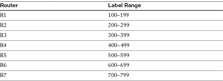
By default, on low-end routers the minimum value within the label range is 16 and the maximum value within the range is 100000. Therefore, the LSR will start assigning labels starting from 16 and will go up to 100000, which means that the LSR can assign up to 99,985 labels (100,000 – 16 + 1 = 99,985). This range can be extended to the maximum allowable range using the MPLS label range 16 1048575 command.
On R1:
R1# show mpls label range
Downstream Generic label region: Min/Max label: 16/100000
You would not normally change a label range after MPLS is fully deployed. The planning of labels should be performed during the initial phase of implementation. However, if they must be changed, a reload is required for the new range to take effect.
Note You would never do this in the production network, unless the range is changed to its maximum allowable value. In this task we will change the default range to include all possible 20 bits, just to demonstrate that we can.
On R1:
R1(config)# mpls label range 16 ?
<16-1048575> Maximum label value for dynamic label range
The following changes the label range based on the task’s requirement:
R1(config)# mpls label range 100 199
Let’s verify the configuration:
On R1:
R1# show mpls label range
Downstream Generic label region: Min/Max label: 16/199
[Configured range for next reload: Min/Max label: 100/199]
Note The preceding show command states that the label range should be from 100 to 199 after a reload; this is why the configured range is between brackets.
Let’s verify the configuration:
On R1:
R1# wr
R1# reload
Here’s what happens when the router comes up:
R1# show mpls label range
Downstream label generic region: min label: 100; max label: 199
On R2:
R2(config)# mpls label range 200 299
On R3:
R3(config)# mpls label range 300 399
On R4:
R4(config)# mpls label range 400 499
On R5:
R5(config)# mpls label range 500 599
On R6:
R6(config)# mpls label range 600 699
On R7:
R7(config)# mpls label range 700 799
Note You may get the following console message on some of the routers; this is not an error message because we don’t have 100 routes in the routing table of any of the routers in this topology. You should save and reload the router; the number of labels stated in the following console message may vary:
On All Routers :
Rx# write
Rx# reload
The label range change will cause 12 labels in the old dynamic range (16–100000) to go out of range.
Let’s look at the new label range:
On R1:
R1# show mpls label range
Downstream Generic label region: Min/Max label: 100/199
R1# show ip route ospf | begin Gate
Gateway of last resort is not set
2.0.0.0/32 is subnetted, 1 subnets
O 2.2.2.2 [110/782] via 12.1.1.2, 00:09:04, Serial1/2
3.0.0.0/32 is subnetted, 1 subnets
O 3.3.3.3 [110/783] via 12.1.1.2, 00:08:14, Serial1/2
4.0.0.0/32 is subnetted, 1 subnets
O 4.4.4.4 [110/784] via 12.1.1.2, 00:07:41, Serial1/2
5.0.0.0/32 is subnetted, 1 subnets
O 5.5.5.5 [110/785] via 12.1.1.2, 00:07:41, Serial1/2
6.0.0.0/32 is subnetted, 1 subnets
O 6.6.6.6 [110/786] via 12.1.1.2, 00:07:41, Serial1/2
7.0.0.0/32 is subnetted, 1 subnets
O 7.7.7.7 [110/787] via 12.1.1.2, 00:07:41, Serial1/2
23.0.0.0/24 is subnetted, 1 subnets
O 23.1.1.0 [110/782] via 12.1.1.2, 00:08:24, Serial1/2
34.0.0.0/24 is subnetted, 1 subnets
O 34.1.1.0 [110/783] via 12.1.1.2, 00:07:51, Serial1/2
45.0.0.0/24 is subnetted, 1 subnets
O 45.1.1.0 [110/784] via 12.1.1.2, 00:07:41, Serial1/2
56.0.0.0/24 is subnetted, 1 subnets
O 56.1.1.0 [110/785] via 12.1.1.2, 00:07:41, Serial1/2
67.0.0.0/24 is subnetted, 1 subnets
O 67.1.1.0 [110/786] via 12.1.1.2, 00:07:41, Serial1/2
Task 8
Examine and describe the control plane for the 7.7.7.0/24 prefix.
Let’s examine the control plane for the 7.7.7.0/24 prefix advertised by R7. We are going to check if the interface is directly connected to R7 and if the interface is in up state:
On R7:
R7# show ip interface brief | exclude unass
Interface IP-Address OK? Method Status Protocol
GigabitEthernet0/0 67.1.1.7 YES NVRAM up up
Loopback0 7.7.7.7 YES NVRAM up up
Loopback1 77.7.7.7 YES NVRAM up up
Let’s look at the routing protocol that is running on this router:
R7# show ip protocol | include Routing Protocol
Routing Protocol is "application"
Routing Protocol is "ospf 1"
Let’s see if OSPF is running on the lo0 interface:
R7# show ip ospf interface brief
Interface PID Area IP Address/Mask Cost State Nbrs F/C
Lo0 1 0 7.7.7.7/24 1 P2P 0/0
Gi0/0 1 0 67.1.1.7/24 1 DR 1/1
The output of the following show command reveals that the local router has assigned imp-null, or label number 3, instructing the neighboring LSR (R6) to pop the label:
R7# show mpls ldp binding 7.7.7.0 24
lib entry: 7.7.7.0/24, rev 4
local binding: label: imp-null
remote binding: lsr: 6.6.6.6:0, label: 600
The entry that is not highlighted will not be used; this is the result of liberal label retention. LSRs generate a label for each route they see in the routing table, and they advertise the routes to their neighboring router. Even though R7 was the LSR that originated the 7.7.7.0/24 prefix, R6 will still advertise a label for that prefix back to R7, but R7 will not use that label at all.
We can see that the local LSR has assigned label 600 to the 7.7.7.0/24 prefix; therefore, it will advertise this label for the 7.7.7.0/24 prefix to R5.
On R6:
R6# show mpls ldp binding 7.7.7.0 24
lib entry: 7.7.7.0/24, rev 31
local binding: label: 600 → Locally originated label for 7.7.7.0
remote binding: lsr: 7.7.7.7:0, label: imp-null → received from R7
remote binding: lsr: 5.5.5.5:0, label: 510
The entry that is not highlighted will not be used; this is the result of liberal label retention.
R5 has assigned label number 510, and it will advertise this label for the 7.7.7.0/24 prefix to the upstream LSR (in this case, R4).
On R5:
R5# show mpls ldp bindings 7.7.7.0 24
lib entry: 7.7.7.0/24, rev 32
local binding: label: 501 → Locally originated label for 7.7.7.0
remote binding: lsr: 6.6.6.6:0, label: 600 → received from R6
remote binding: lsr: 4.4.4.4:0, label: 407
The entry that is not highlighted will not be used; this is the result of liberal label retention.
R4 has assigned label number 410, and it will advertise this label for the 7.7.7.0/24 prefix to its upstream LSR (R3).
On R4:
R4# show mpls ldp binding 7.7.7.0 24
lib entry: 7.7.7.0/24, rev 32
local binding: label: 407 → Locally originated for 7.7.7.0
remote binding: lsr: 5.5.5.5:0, label: 501 → received from R5
remote binding: lsr: 3.3.3.3:0, label: 308
The entry that is not highlighted will not be used; this is the result of liberal label retention.
R3 has assigned label 308, and it will advertise this label for 7.7.7.0/24 to its upstream LSR (R2).
On R3:
R3# show mpls ldp binding 7.7.7.0 24
lib entry: 7.7.7.0/24, rev 32
local binding: label: 308 → Locally originated for 7.7.7.0
remote binding: lsr: 4.4.4.4:0, label: 407 → received from R4
remote binding: lsr: 2.2.2.2:0, label: 208
The entry that is not highlighted will not be used; this is the result of liberal label retention.
R2 has assigned label 210, and it will advertise this label for 7.7.7.0/24 to its upstream LSR (R1).
On R2:
R2# show mpls ldp binding 7.7.7.0 24
lib entry: 7.7.7.0/24, rev 31
local binding: label: 208 → Locally originated for 7.7.7.0
remote binding: lsr: 3.3.3.3:0, label: 308 → received from R3
remote binding: lsr: 11.1.1.1:0, label: 107
The entry that is not highlighted will not be used; this is the result of liberal label retention.
Even though R1 doesn’t have any upstream LDP neighbor, it still generates a label for the 7.7.7.0/24 prefix.
On R1:
R1# show mpls ldp bindings 7.7.7.0 24
lib entry: 7.7.7.0/24, rev 29
local binding: label: 107 → Locally originated
remote binding: lsr: 2.2.2.2:0, label: 208 → received from R2
Task 9
Examine and describe the data plane for the 7.7.7.0/24 prefix.
Let’s examine the data plane for the 7.7.7.0/24 prefix; in this case, we need to start from R1:
On R1:
R1# show ip cef 7.7.7.0/24 detail
7.7.7.0/24, epoch 0
local label info: global/107
nexthop 12.1.1.2 Serial1/2 label 208
You can see that if the local router receives an IP packet destined to 7.7.7.0/24, it will impose label 210 and will exit out of S1/2 and go to the 12.1.1.2 IP address as the labeled packet.
Here’s another way to display the data plane information (LFIB) for 7.7.7.0/24:
R1# show mpls ip binding 7.7.7.0 24
7.7.7.0/24
in label: 107 → This is locally generated label and it's ignored
out label: 208 lsr: 2.2.2.2:0 inuse
You can see that the local router (R1) uses label 208 to forward the traffic toward the 7.7.7.0/24 prefix. Let’s verify this information by looking in the LFIB:
R1# show mpls forwarding-table 7.7.7.0 24
Local Outgoing Prefix Bytes Label Outgoing Next Hop
Label Label or Tunnel Id Switched interface
107 208 7.7.7.0/24 0 Se1/2 point2point
Note R1 is the ingress LSR for the 7.7.7.0/24 prefix, so when it receives an IP packet, it will impose label 208 and forward the packet as a labeled packet out of its S1/2 interface toward 7.7.7.0/24.
When R2 receives a labeled packet with the top label of 208, it will swap it with label 308 and then forward the packet out of its f0/0 interface to the 23.1.1.3 IP address toward the 7.7.7.0/24 prefix:
On R2:
R2# show mpls forwarding-table 7.7.7.0 24
Local Outgoing Prefix Bytes Label Outgoing Next Hop
Label Label or Tunnel Id Switched interface
208 308 7.7.7.0/24 0 Fa0/0 23.1.1.3
When R3 receives a labeled packet with the top label of 308, it will swap that label with label 407 and it’ll forward the packet out of its S1/4 interface toward the 7.7.7.0/24 prefix:
On R3:
R3# show mpls for 7.7.7.0 24
Local Outgoing Prefix Bytes Label Outgoing Next Hop
Label Label or Tunnel Id Switched interface
308 407 7.7.7.0/24 0 Se1/4 point2point
Note Because the connection between R3 and R4 is a serial back-to-back connection, the next hop shows up as P2P, whereas on Ethernet links the IP address of the next hop is displayed.
When R4 receives a labeled packet with the top label of 407, it will swap that label with label 501 and will forward the packet out of its S1/5 interface toward the 7.7.7.0/24 prefix:
On R4:
R4# show mpls forwarding-table 7.7.7.0 24
Local Outgoing Prefix Bytes Label Outgoing Next Hop
Label Label or Tunnel Id Switched interface
407 501 7.7.7.0/24 0 Se1/5 point2point
When R5 receives a labeled packet with the top label of 501, it will swap that label with label 600 and will forward the packet out of its F0/1 interface toward the 7.7.7.7/32 prefix:
On R5:
R5# show mpls forwarding-table 7.7.7.0 24
Local Outgoing Prefix Bytes Label Outgoing Next Hop
Label Label or Tunnel Id Switched interface
501 600 7.7.7.0/24 0 Fa0/1 56.1.1.6
When R6, the second-last-hop router (the penultimate router) receives a labeled packet with the top label of 600, it will pop that label and forward the packet out of its F0/0 interface toward the 7.7.7.0/24 prefix:
On R6:
R6# show mpls forwarding-table 7.7.7.0 24
Local Outgoing Prefix Bytes Label Outgoing Next Hop
Label Label or Tunnel Id Switched interface
600 Pop Label 7.7.7.0/24 0 Fa0/0 67.1.1.7
Since R7 receives an IP packet and not a labeled packet, it checks its FIB:
On R7:
R7# Show ip cef 7.7.7.0/24
7.7.7.0/24
receive for Loopback0
R7# show mpls forwarding-table 7.7.7.0 24
Local Outgoing Prefix Bytes Label Outgoing Next Hop
Label Label or Tunnel Id Switched interface
None No Label 7.7.7.0/24 0 drop
Note The IP packet is received by the local router, and there is no outgoing label.
Task 10
Configure LDP conditional label advertising to exclude the links that interconnect the routers in this topology.
Configure R1 to stop advertising labels:
On R1:
R1(config)# no mpls ldp advertise-labels
Let’s verify the configuration:
On R2:
R2# show mpls ldp binding neighbor 11.1.1.1
Note The output of the preceding show command reveals that R2 is no longer receiving any labels from R1.
Configure an access list to deny the networks assigned to the links that interconnect the LSRs and allow everything else; this access list will be referenced by the FOR keyword of the mpls ldp advertise-labels command:
On R1:
R1(config)# access-list 1 deny 12.1.1.0 0.0.0.255
R1(config)# access-list 1 deny 23.1.1.0 0.0.0.255
R1(config)# access-list 1 deny 34.1.1.0 0.0.0.255
R1(config)# access-list 1 deny 45.1.1.0 0.0.0.255
R1(config)# access-list 1 deny 56.1.1.0 0.0.0.255
R1(config)# access-list 1 deny 67.1.1.0 0.0.0.255
R1(config)# access-list 1 permit any
Configure an access list to identify the peer(s) that the labels will be advertised to; this access list will be referenced by the TO keyword of the mpls ldp advertise-labels command:
R1(config)# access-list 2 permit any
Configure the mpls ldp advertise-labels command to reference the two access lists:
Now let’s verify the configuration:
On R2:
R2# show mpls ldp binding neighbor 11.1.1.1
lib entry: 1.1.1.1/32, rev 12
remote binding: lsr: 11.1.1.1:0, label: imp-null
lib entry: 2.2.2.2/32, rev 6
remote binding: lsr: 11.1.1.1:0, label: 100
lib entry: 3.3.3.3/32, rev 18
remote binding: lsr: 11.1.1.1:0, label: 104
lib entry: 4.4.4.4/32, rev 16
remote binding: lsr: 11.1.1.1:0, label: 103
lib entry: 5.5.5.5/32, rev 14
remote binding: lsr: 11.1.1.1:0, label: 102
lib entry: 6.6.6.6/32, rev 28
remote binding: lsr: 11.1.1.1:0, label: 108
lib entry: 7.7.7.0/24, rev 31
remote binding: lsr: 11.1.1.1:0, label: 110
lib entry: 11.1.1.1/32, rev 10
remote binding: lsr: 11.1.1.1:0, label: imp-null
Note R1 (11.1.1.1) is no longer advertising the links to this neighbor. R1 will assign labels to the links that interconnect the LSRs, but it won’t advertise them to its neighboring LSR(s). Let’s take a look:
On R1:
R1# Show mpls ldp bindings local
lib entry: 1.1.1.1/32, rev 45
local binding: label: imp-null
lib entry: 2.2.2.2/32, rev 46
local binding: label: 100
lib entry: 3.3.3.3/32, rev 47
local binding: label: 104
lib entry: 4.4.4.4/32, rev 48
local binding: label: 103
lib entry: 5.5.5.5/32, rev 49
local binding: label: 102
lib entry: 6.6.6.6/32, rev 50
local binding: label: 108
lib entry: 7.7.7.0/24, rev 51
local binding: label: 110
lib entry: 11.1.1.1/32, rev 52
local binding: label: imp-null
lib entry: 12.1.1.0/24, rev 38
local binding: label: imp-null
lib entry: 23.1.1.0/24, rev 40
local binding: label: 101
lib entry: 34.1.1.0/24, rev 41
local binding: label: 107
lib entry: 45.1.1.0/24, rev 42
local binding: label: 106
lib entry: 56.1.1.0/24, rev 43
local binding: label: 105
lib entry: 67.1.1.0/24, rev 44
local binding: label: 109
On All Routers:
Rx(config)# no mpls ldp advertise-labels
Rx(config)# access-list 1 deny 12.1.1.0 0.0.0.255
Rx(config)# access-list 1 deny 23.1.1.0 0.0.0.255
Rx(config)# access-list 1 deny 34.1.1.0 0.0.0.255
Rx(config)# access-list 1 deny 45.1.1.0 0.0.0.255
Rx(config)# access-list 1 deny 56.1.1.0 0.0.0.255
Rx(config)# access-list 1 deny 67.1.1.0 0.0.0.255
Rx(config)# access-list 1 permit any
Rx(config)# access-list 2 permit any
Rx(config)# mpls ldp advertise-labels for 1 to 2
Now let’s verify the configuration:
On R7:
R7# show mpls ldp binding neighbor 6.6.6.6
lib entry: 1.1.1.1/32, rev 42
remote binding: lsr: 6.6.6.6:0, label: 605
lib entry: 2.2.2.2/32, rev 43
remote binding: lsr: 6.6.6.6:0, label: 604
lib entry: 3.3.3.3/32, rev 44
remote binding: lsr: 6.6.6.6:0, label: 603
lib entry: 4.4.4.4/32, rev 45
remote binding: lsr: 6.6.6.6:0, label: 602
lib entry: 5.5.5.5/32, rev 46
remote binding: lsr: 6.6.6.6:0, label: 601
lib entry: 6.6.6.0/24, rev 47
remote binding: lsr: 6.6.6.6:0, label: imp-null
lib entry: 7.7.7.0/24, rev 48
remote binding: lsr: 6.6.6.6:0, label: 610
lib entry: 11.1.1.1/32, rev 49
remote binding: lsr: 6.6.6.6:0, label: 600
lib entry: 66.6.6.0/24, rev 55
remote binding: lsr: 6.6.6.6:0, label: imp-null
On R6:
R6# show mpls ldp binding neighbor 5.5.5.5
lib entry: 1.1.1.1/32, rev 50
remote binding: lsr: 5.5.5.5:0, label: 506
lib entry: 2.2.2.2/32, rev 51
remote binding: lsr: 5.5.5.5:0, label: 505
lib entry: 3.3.3.3/32, rev 52
remote binding: lsr: 5.5.5.5:0, label: 501
lib entry: 4.4.4.4/32, rev 53
remote binding: lsr: 5.5.5.5:0, label: 500
lib entry: 5.5.5.0/24, rev 54
remote binding: lsr: 5.5.5.5:0, label: imp-null
lib entry: 6.6.6.6/32, rev 55
remote binding: lsr: 5.5.5.5:0, label: 508
lib entry: 7.7.7.0/24, rev 56
remote binding: lsr: 5.5.5.5:0, label: 510
lib entry: 11.1.1.1/32, rev 57
remote binding: lsr: 5.5.5.5:0, label: 504
lib entry: 55.5.5.0/24, rev 58
remote binding: lsr: 5.5.5.5:0, label: imp-null
On R5:
R5# show mpls ldp binding neighbor 4.4.4.4
lib entry: 1.1.1.1/32, rev 50
remote binding: lsr: 4.4.4.4:0, label: 406
lib entry: 2.2.2.2/32, rev 51
remote binding: lsr: 4.4.4.4:0, label: 405
lib entry: 3.3.3.3/32, rev 52
remote binding: lsr: 4.4.4.4:0, label: 400
lib entry: 4.4.4.0/24, rev 53
remote binding: lsr: 4.4.4.4:0, label: imp-null
lib entry: 5.5.5.5/32, rev 54
remote binding: lsr: 4.4.4.4:0, label: 402
lib entry: 6.6.6.6/32, rev 55
remote binding: lsr: 4.4.4.4:0, label: 408
lib entry: 7.7.7.0/24, rev 56
remote binding: lsr: 4.4.4.4:0, label: 410
lib entry: 11.1.1.1/32, rev 57
remote binding: lsr: 4.4.4.4:0, label: 404
lib entry: 44.4.4.0/24, rev 58
remote binding: lsr: 4.4.4.4:0, label: imp-null
On R4:
R4# show mpls ldp binding neighbor 3.3.3.3
lib entry: 1.1.1.1/32, rev 50
remote binding: lsr: 3.3.3.3:0, label: 306
lib entry: 2.2.2.2/32, rev 51
remote binding: lsr: 3.3.3.3:0, label: 305
lib entry: 3.3.3.0/24, rev 52
remote binding: lsr: 3.3.3.3:0, label: imp-null
lib entry: 4.4.4.4/32, rev 53
remote binding: lsr: 3.3.3.3:0, label: 300
lib entry: 5.5.5.5/32, rev 54
remote binding: lsr: 3.3.3.3:0, label: 302
lib entry: 6.6.6.6/32, rev 55
remote binding: lsr: 3.3.3.3:0, label: 308
lib entry: 7.7.7.0/24, rev 56
remote binding: lsr: 3.3.3.3:0, label: 310
lib entry: 11.1.1.1/32, rev 57
remote binding: lsr: 3.3.3.3:0, label: 304
lib entry: 33.3.3.0/24, rev 58
remote binding: lsr: 3.3.3.3:0, label: imp-null
On R3:
R3# show mpls ldp binding neighbor 2.2.2.2
lib entry: 1.1.1.1/32, rev 50
remote binding: lsr: 2.2.2.2:0, label: 201
lib entry: 2.2.2.0/24, rev 51
remote binding: lsr: 2.2.2.2:0, label: imp-null
lib entry: 3.3.3.3/32, rev 52
remote binding: lsr: 2.2.2.2:0, label: 204
lib entry: 4.4.4.4/32, rev 53
remote binding: lsr: 2.2.2.2:0, label: 203
lib entry: 5.5.5.5/32, rev 54
remote binding: lsr: 2.2.2.2:0, label: 202
lib entry: 6.6.6.6/32, rev 55
remote binding: lsr: 2.2.2.2:0, label: 208
lib entry: 7.7.7.0/24, rev 56
remote binding: lsr: 2.2.2.2:0, label: 210
lib entry: 11.1.1.1/32, rev 57
remote binding: lsr: 2.2.2.2:0, label: 200
lib entry: 22.2.2.0/24, rev 58
remote binding: lsr: 2.2.2.2:0, label: imp-null
On R2:
R2# show mpls ldp binding neighbor 11.1.1.1
lib entry: 1.1.1.0/24, rev 48
remote binding: lsr: 11.1.1.1:0, label: imp-null
lib entry: 2.2.2.2/32, rev 49
remote binding: lsr: 11.1.1.1:0, label: 100
lib entry: 3.3.3.3/32, rev 50
remote binding: lsr: 11.1.1.1:0, label: 104
lib entry: 4.4.4.4/32, rev 51
remote binding: lsr: 11.1.1.1:0, label: 103
lib entry: 5.5.5.5/32, rev 52
remote binding: lsr: 11.1.1.1:0, label: 102
lib entry: 6.6.6.6/32, rev 53
remote binding: lsr: 11.1.1.1:0, label: 108
lib entry: 7.7.7.0/24, rev 54
remote binding: lsr: 11.1.1.1:0, label: 110
lib entry: 11.1.1.0/24, rev 55
remote binding: lsr: 11.1.1.1:0, label: imp-null
Task 11
In this task, the effects of TTL propagation will be tested.
Remove the mpls ip command from the F0/0 interface of R6, the G0/0 interface of R7, and the serial interfaces of R1 and R2 that connect the two LSRs. R1 and R7 will pose as customer routers that do not have MPLS enabled. From R7, test the connection to 1.1.1.1 using traceroute.
On R1:
R1(config)# interface Serial1/2
R1(config-if)# no mpls ip
On R2:
R2(config)# interface Serial1/1
R2(config-if)# no mpls ip
On R7:
R7(config)# interface GigabitEthernet0/0
R7(config-if)# no mpls ip
On R6:
R6(config)# interface FastEthernet0/0
R6(config-if)# no mpls ip
Let’s test the configuration:
On R7:
R7# traceroute 1.1.1.1 numeric
Type escape sequence to abort.
Tracing the route to 1.1.1.1
VRF info: (vrf in name/id, vrf out name/id)
1 67.1.1.6 0 msec 4 msec 0 msec
2 56.1.1.5 [MPLS: Label 507 Exp 0] 140 msec 136 msec 140 msec
3 45.1.1.4 [MPLS: Label 405 Exp 0] 120 msec 124 msec 124 msec
4 34.1.1.3 [MPLS: Label 303 Exp 0] 108 msec 108 msec 116 msec
5 23.1.1.2 [MPLS: Label 201 Exp 0] 64 msec 60 msec 64 msec
6 12.1.1.1 48 msec * 48 msec
The traceroute exposes all the links and labels within the provider’s network.
Task 12
Reconfigure the appropriate router(s) such that a traceroute from R7 to 1.1.1.1 or R1 to 7.7.7.7 will not display the links from the provider’s network.
The following command has two optional keywords that can be used:
![]() forwarded: Propagates IP TTL for forwarded traffic. This option will hide the MPLS structure from the customers.
forwarded: Propagates IP TTL for forwarded traffic. This option will hide the MPLS structure from the customers.
![]() local: Propagates IP TTL for locally originated traffic. This option will hide the MPLS structure from the LSRs.
local: Propagates IP TTL for locally originated traffic. This option will hide the MPLS structure from the LSRs.
On R2 to R6:
Rx(config)# no mpls ip propagate-ttl forwarded
Let’s verify the configuration:
On R7:
R7# traceroute 1.1.1.1 numeric
Type escape sequence to abort.
Tracing the route to 1.1.1.1
VRF info: (vrf in name/id, vrf out name/id)
1 67.1.1.6 0 msec 4 msec 0 msec
2 23.1.1.2 [MPLS: Label 201 Exp 0] 64 msec 60 msec 64 msec
3 12.1.1.1 48 msec * 48 msec
Note The MPLS structure is hidden from the customer’s perspective. The only internal hop and label exposed is the last-hop LSR (23.1.1.2), but the following traceroute reveals that the LSRs within the cloud will see the structure of the cloud:
On R2:
R2# traceroute 7.7.7.7 numeric
Type escape sequence to abort.
Tracing the route to 7.7.7.7
VRF info: (vrf in name/id, vrf out name/id)
1 23.1.1.3 [MPLS: Label 308 Exp 0] 92 msec 96 msec 92 msec
2 34.1.1.4 [MPLS: Label 407 Exp 0] 76 msec 76 msec 76 msec
3 45.1.1.5 [MPLS: Label 501 Exp 0] 60 msec 64 msec 60 msec
4 56.1.1.6 [MPLS: Label 600 Exp 0] 64 msec 60 msec 64 msec
5 67.1.1.7 32 msec * 32 msec
Let’s test the second option (local). The following command will override the previous one:
On R2 to R6:
Rx(config)# no mpls ip propagate-ttl local
Let’s verify the configuration:
On R1:
R1# traceroute 7.7.7.7 numeric
Type escape sequence to abort.
Tracing the route to 7.7.7.7
VRF info: (vrf in name/id, vrf out name/id)
1 12.1.1.2 16 msec 12 msec 16 msec
2 23.1.1.3 [MPLS: Label 308 Exp 0] 124 msec 120 msec 120 msec
3 34.1.1.4 [MPLS: Label 407 Exp 0] 108 msec 104 msec 108 msec
4 45.1.1.5 [MPLS: Label 501 Exp 0] 88 msec 92 msec 88 msec
5 56.1.1.6 [MPLS: Label 600 Exp 0] 88 msec 88 msec 88 msec
6 67.1.1.7 48 msec * 44 msec
This reveals that the no mpls ip propagate-ttl local command does not affect the customers.
Note As you can see here, the no mpls ip propagate-ttl local command only affected the LSRs within the cloud:
Task 13
Remove the mpls ip command from all interfaces and verify the configuration:
On R2:
R2(config)# interface FastEthernet0/0
R2(config-if)# no mpls ip
R2# show mpls interface
Interface IP Tunnel BGP Static Operational
On R3:
R3(config)# interface FastEthernet0/0
R3(config-if)# no mpls ip
R3(config)# interface Serial1/4
R3(config-if)# no mpls ip
R3# show mpls interface
Interface IP Tunnel BGP Static Operational
On R4:
R4(config)# interface Serial1/3
R4(config-if)# no mpls ip
R4(config)# interface Serial1/5
R4(config-if)# no mpls ip
R4# show mpls interface
Interface IP Tunnel BGP Static Operational
On R5:
R5(config)# interface FastEthernet0/1
R5(config-if)# no mpls ip
R5(config)# interface Serial1/4
R5(config-if)# no mpls ip
R5# show mpls interface
Interface IP Tunnel BGP Static Operational
On R6:
R6(config)# interface FastEthernet0/1
R6(config-if)# no mpls ip
R2# show mpls interface
Interface IP Tunnel BGP Static Operational
Task 14
Enable LDP on all the links connecting the routers to each other. This should include R1 and R7. Do not use the mpls ip interface configuration mode command or a global configuration command to accomplish this task.
LDP is enabled by configuring mpls ip in the interface configuration mode; typically, some type of IGP will need to run on that given interface. To minimize the configuration and errors (forgetting to enable LDP on a given interface), LDP autoconfiguration can be used. When this feature is enabled, LDP is automatically enabled on every interface of that LSR. However, if LDP must be disabled for a given interface, you can use the no mpls ldp igp autoconfig interface configuration mode. In this case, because OSPF is running as the IGP within the MPLS cloud, LDP autoconfiguration is enabled for all interfaces within Area 0.
On R7:
R7(config)# router ospf 1
R7(config-router)# mpls ldp autoconfig area 0
Let’s verify the configuration on R7:
On R7:
R7# show mpls interfaces
Interface IP Tunnel BGP Static Operational
GigabitEthernet0/0 Yes (ldp) No No No Yes
On R6:
R6(config)# router ospf 1
R6(config-router)# mpls ldp autoconfig area 0
Let’s verify the configuration on R6:
On R6:
R6# show mpls interfaces
Interface IP Tunnel BGP Static Operational
FastEthernet0/0 Yes (ldp) No No No Yes
FastEthernet0/1 Yes (ldp) No No No Yes
You should see the following console message:
%LDP-5-NBRCHG: LDP Neighbor 7.7.7.7:0 (1) is UP
On R5:
R5(config)# router ospf 1
R5(config-router)# mpls ldp autoconfig area 0
Let’s verify the configuration on R5:
On R5:
R5# show mpls interfaces
Interface IP Tunnel BGP Static Operational
Serial1/4 Yes (ldp) No No No Yes
FastEthernet0/1 Yes (ldp) No No No Yes
You should see the following console message:
%LDP-5-NBRCHG: LDP Neighbor 6.6.6.6:0 (1) is UP
On R4:
R4(config)# router ospf 1
R4(config-router)# mpls ldp autoconfig area 0
Let’s verify the configuration on R4:
On R4:
R4# show mpls interfaces
Interface IP Tunnel BGP Static Operational
Serial1/3 Yes (ldp) No No No Yes
Serial1/5 Yes (ldp) No No No Yes
You should see the following console message:
%LDP-5-NBRCHG: LDP Neighbor 5.5.5.5:0 (1) is UP
On R3:
R3(config)# router ospf 1
R3(config-router)# mpls ldp autoconfig area 0
Let’s verify the configuration on R3:
On R3:
R3# show mpls interfaces
Interface IP Tunnel BGP Static Operational
FastEthernet0/0 Yes (ldp) No No No Yes
Serial1/4 Yes (ldp) No No No Yes
You should see the following console message:
%LDP-5-NBRCHG: LDP Neighbor 4.4.4.4:0 (1) is UP
%LDP-5-NBRCHG: LDP Neighbor 2.2.2.2:0 (2) is UP
On R2:
R2(config)# router ospf 1
R2(config-router)# mpls ldp autoconfig area 0
Let’s verify the configuration on R2:
On R2:
R2# show mpls interfaces
Interface IP Tunnel BGP Static Operational
FastEthernet0/0 Yes (ldp) No No No Yes
Serial1/1 Yes (ldp) No No No Yes
You should see the following console message:
%LDP-5-NBRCHG: LDP Neighbor 3.3.3.3:0 (1) is UP
On R1:
R1(config)# router ospf 1
R1(config-router)# mpls ldp autoconfig area 0
Let’s verify the configuration on R1:
On R1:
R1# show mpls interfaces
Interface IP Tunnel BGP Static Operational
Serial1/2 Yes (ldp) No No No Yes
You should see the following console message:
%LDP-5-NBRCHG: LDP Neighbor 2.2.2.2:0 (1) is UP
Task 15
Configure a serial connection between R3 and R5 using the following parameters and policy:
R3: S1/5, 35.1.1.3/24, bandwidth 1544
R5: S1/3, 35.1.1.5/24, bandwidth 1544
This link should be included in OSPF Area 0:
On R3:
R3(config)# interface Serial1/5
R3(config-if)# ip address 35.1.1.3 255.255.255.0
R3(config-if)# clock rate 64000
R3(config-if)# bandwidth 1544
R3(config-if)# no shutdown
R3(config)# router ospf 1
R3(config-router)# network 35.1.1.3 0.0.0.0 area 0
On R5:
R5(config)# interface Serial1/3
R5(config-if)# ip address 35.1.1.5 255.255.255.0
R5(config-if)# bandwidth 1544
R5(config-if)# no shutdown
R5(config)# router ospf 1
R5(config-router)# network 35.1.1.5 0.0.0.0 area 0
You should see the following console messages stating that OSPF and an LDP session have been established between the two LSRs. The LDP session is established between the two LSRs because of the mpls ldp autoconfig area 0 command from the previous task.
%OSPF-5-ADJCHG: Process 1, Nbr 0.0.0.3 on Serial1/3 from LOADING to FULL, Loading Done
%LDP-5-NBRCHG: LDP Neighbor 3.3.3.3:0 (3) is UP
Let’s verify the configuration:
On R3:
R3# show mpls ldp neighbor 5.5.5.5
Peer LDP Ident: 5.5.5.5:0; Local LDP Ident 3.3.3.3:0
TCP connection: 5.5.5.5.16346 - 3.3.3.3.646
State: Oper; Msgs sent/rcvd: 15/15; Downstream
Up time: 00:01:07
LDP discovery sources:
Serial1/5, Src IP addr: 35.1.1.5
Addresses bound to peer LDP Ident:
56.1.1.5 5.5.5.5 55.5.5.5 45.1.1.5
35.1.1.5
Task 16
Configure the appropriate router(s) such that a failure in one of the links between R3 and R5 does not tear down the LDP session between the two LSRs. Do not configure a GRE or an IPnIP tunnel to accomplish this task.
When a link between two LSRs goes down, the two LSRs that share the link will tear down the LDP session. When the link comes back up, the two LSRs have to reestablish their session and populate the Label Information Base (LIB) and the Label Forwarding Information Base (LFIB). This behavior can be changed by protecting the LDP session using a feature called LDP session protection.
With LDP session protection, a targeted LDP session is built between the routers that have this feature configured. When the directly connected link goes down, the targeted LDP session remains up as long as a redundant link exists between the two LSRs.
This feature can be enabled using the mpls ldp session protection global configuration command.
There are two ways to configure LDP session protection:
![]() Configure the feature on all routers.
Configure the feature on all routers.
![]() Configure the feature on one router and then configure the other router to accept the targeted LDP hellos. This can be accomplished using the mpls ldp discovery targeted-hello accept global configuration command.
Configure the feature on one router and then configure the other router to accept the targeted LDP hellos. This can be accomplished using the mpls ldp discovery targeted-hello accept global configuration command.
In this case, the MPLS LDP session protection must be configured on R3, R4, and R5 because they have redundant links between them.
On R3:
R3# show mpls ldp neighbor | include Peer LDP
Peer LDP Ident: 5.5.5.5:0; Local LDP Ident 3.3.3.3:0
Peer LDP Ident: 2.2.2.2:0; Local LDP Ident 3.3.3.3:0
Peer LDP Ident: 4.4.4.4:0; Local LDP Ident 3.3.3.3:0
Let’s shut down the s1/4 interface to emulate a link failure and see the result:
R3(config)# interface Serial1/4
R3(config-if)# shutdown
You should see the following console messages:
%OSPF-5-ADJCHG: Process 1, Nbr 0.0.0.4 on Serial1/4 from FULL to DOWN, Neighbor Down: Interface down or detached
%LDP-5-NBRCHG: LDP Neighbor 4.4.4.4:0 (1) is DOWN (Interface not operational)
%LINK-5-CHANGED: Interface Serial1/4, changed state to administratively down
%LINEPROTO-5-UPDOWN: Line protocol on Interface Serial1/4, changed state to down
Note Because the link that R3 and R4 share is down, the LDP session is torn down as well.
Let’s look at the existing LDP sessions:
R3# show mpls ldp neigh | include Peer LDP
Peer LDP Ident: 2.2.2.2:0; Local LDP Ident 3.3.3.3:0
Peer LDP Ident: 5.5.5.5:0; Local LDP Ident 3.3.3.3:0
You can see that R3 has two LDP sessions: one with R2 and another with R5.
Let’s bring the s1/4 interface back up and configure the LDP session protection feature:
On R3:
R3(config)# interface Serial1/4
R3(config-if)# no shutdown
You should see the following console messages:
%LINK-3-UPDOWN: Interface Serial1/4, changed state to up
%LDP-5-NBRCHG: LDP Neighbor 4.4.4.4:0 (1) is UP
%LINEPROTO-5-UPDOWN: Line protocol on Interface Serial1/4, changed state to up
%OSPF-5-ADJCHG: Process 1, Nbr 0.0.0.4 on Serial1/4 from LOADING to FULL, Loading Done
We will now need to verify the mpls neighbors directly. We will start on R3.
On R3:
R3# show mpls ldp neighbor | include Peer LDP
Peer LDP Ident: 5.5.5.5:0; Local LDP Ident 3.3.3.3:0
Peer LDP Ident: 2.2.2.2:0; Local LDP Ident 3.3.3.3:0
Peer LDP Ident: 4.4.4.4:0; Local LDP Ident 3.3.3.3:0
On R3, R4, and R5:
Rx(config)# mpls ldp session protection
We will also want to look at the specific discovery mechanisms used to form these neighbors.
On R3:
R3# show mpls ldp discovery
Local LDP Identifier:
3.3.3.3:0
Discovery Sources:
Interfaces:
FastEthernet0/0 (ldp): xmit/recv
LDP Id: 2.2.2.2:0
Serial1/4 (ldp): xmit/recv
LDP Id: 4.4.4.4:0
Serial1/5 (ldp): xmit/recv
LDP Id: 5.5.5.5:0
Targeted Hellos:
3.3.3.3 -> 2.2.2.2 (ldp): active, xmit
3.3.3.3 -> 5.5.5.5 (ldp): active/passive, xmit/recv
LDP Id: 5.5.5.5:0
3.3.3.3 -> 4.4.4.4 (ldp): active/passive, xmit/recv
LDP Id: 4.4.4.4:0
You can see the targeted hellos in full mesh.
Let’s test the configuration:
On R3:
R3# debug mpls ldp session protection
LDP session protection events debugging is on
R3(config)# interface Serial1/4
R3(config-if)# shutdown
You should see the following debug output which indicates clearly that the OSPF adjacency is torn down:
%OSPF-5-ADJCHG: Process 1, Nbr 0.0.0.4 on Serial1/4 from FULL to DOWN,
Neighbor Down: Interface down or detached
The primary LDP adjacency is lost, the holddown timer has started counting down, and the LDP session has transitioned from ready to protecting. The holddown timer is typically one hour:
LDP SP: 4.4.4.4:0: last primary adj lost; starting session protection holdup timer
LDP SP: 4.4.4.4:0: LDP session protection holdup timer started, 86400 seconds
LDP SP: 4.4.4.4:0: state change (Ready -> Protecting)
%LDP-5-SP: 4.4.4.4:0: session hold up initiated
%LDP-5-SP: 4.4.4.4:0: session hold up initiated
%OSPF-5-ADJCHG: Process 1, Nbr 0.0.0.4 on Serial1/4 from FULL to DOWN, Neighbor Down: Interface down or detached
%LINK-5-CHANGED: Interface Serial1/4, changed state to administratively down
%LINEPROTO-5-UPDOWN: Line protocol on Interface Serial1/4, changed state to down
Let’s verify the configuration:
On R3:
R3# show mpls ldp neighbor | include Peer LDP
Peer LDP Ident: 2.2.2.2:0; Local LDP Ident 3.3.3.3:0
Peer LDP Ident: 5.5.5.5:0; Local LDP Ident 3.3.3.3:0
Peer LDP Ident: 4.4.4.4:0; Local LDP Ident 3.3.3.3:0
Let’s bring up the link and observe the debug and console output:
R3(config)# interface Serial1/4
R3(config-if)# no shutdown
You should see the following console messages and debug output:
%LINK-3-UPDOWN: Interface Serial1/4, changed state to up
LDP SP: 4.4.4.4:0: primary adj restored; stopping session protection holdup timer
LDP SP: 4.4.4.4:0: state change (Protecting -> Ready)
%LDP-5-SP: 4.4.4.4:0: session recovery succeeded
%LINEPROTO-5-UPDOWN: Line protocol on Interface Serial1/4, changed state to up
%OSPF-5-ADJCHG: Process 1, Nbr 0.0.0.4 on Serial1/4 from LOADING to FULL, Loading Done
Erase the startup configuration of the routers and reload them before proceeding to the next lab.
Lab 15-2: RIPv2 Routing in a VPN
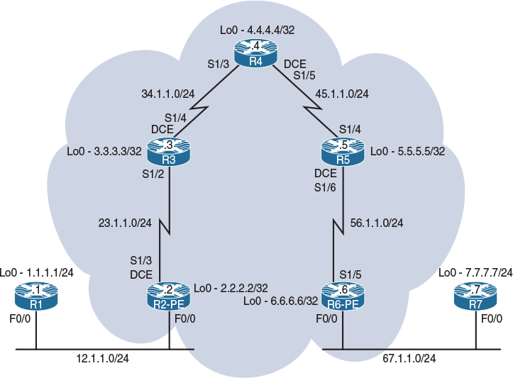
Figure 15-2 Configuring RIPv2 Routing in a VPN
RIPv2 as a PE-CE routing protocol is used by service providers for customers who use RIPv2 as their IGP routing protocol and, hence, prefer to use RIPv2 to exchange routing information between the customer sites across an MPLS VPN backbone. In an MPLS VPN environment, to achieve this, the original RIPv2 metrics must be carried inside Multi-Protocol-BGP (MP-BGP) updates. This is achieved by using BGP extended community attributes to carry and preserve RIPv2 metrics when crossing the MultiProtocol-interiorBGP (MP-iBGP) domain. These communities define the native characteristics associated with RIPv2.
Route propagation in MPLS VPN networks using RIPv2 PE-CE routing is based on the RIPv2 domain configured on the PE routers:
Step 1. Enable the global RIPv2 routing process.
Step 2. Define per VRF (Virtual Routing and Forwarding) the EIGRP routing context and parameters.
Step 3. Configure the MP-BGP VPNv4 backbone.
Step 4. Redistribute BGP VPNv4 routes in RIPv2.
Step 5. Redistribute Routing Information Protocol (RIP) routes in BGP.
Task 1
Configure the topology shown in Figure 15-2. Do not configure any routing protocol. Use a VLAN ID of your choice.
On SW1:
SW1(config)# interface range FastEthernet0/1-2
SW1(config-if-range)# switchport mode access
SW1(config-if-range)# switchport access vlan 12
% Access VLAN does not exist. Creating vlan 12
SW1(config-if-range)# no shutdown
SW1(config)# interface range FastEthernet0/6-7
SW1(config-if-range)# switchport mode access
SW1(config-if-range)# switchport access vlan 67
% Access VLAN does not exist. Creating vlan 67
SW1(config-if-range)# no shutdown
On R1:
R1(config)# interface loopback0
R1(config-if)# ip address 1.1.1.1 255.255.255.0
R1(config)# interface FastEthernet0/0
R1(config-if)# ip address 12.1.1.1 255.255.255.0
R1(config-if)# no shutdown
On R2:
R2(config)# interface loopback0
R2(config-if)# ip address 2.2.2.2 255.255.255.255
R2(config)# interface FastEthernet0/0
R2(config-if)# ip address 12.1.1.2 255.255.255.0
R2(config-if)# no shutdown
R2(config-if)# interface Serial1/3
R2(config-if)# clock rate 64000
R2(config-if)# ip address 23.1.1.2 255.255.255.0
R2(config-if)# no shutdown
On R3:
R3(config)# interface loopback0
R3(config-if)# ip address 3.3.3.3 255.255.255.255
R3(config)# interface Serial1/2
R3(config-if)# ip address 23.1.1.3 255.255.255.0
R3(config-if)# no shutdown
R3(config)# interface Serial1/4
R3(config-if)# clock rate 64000
R3(config-if)# ip address 34.1.1.3 255.255.255.0
R3(config-if)# no shutdown
On R4:
R4(config)# interface loopback0
R4(config-if)# ip address 4.4.4.4 255.255.255.255
R4(config)# interface Serial1/3
R4(config-if)# ip address 34.1.1.4 255.255.255.0
R4(config-if)# no shutdown
R4(config)# interface Serial1/5
R4(config-if)# clock rate 64000
R4(config-if)# ip address 45.1.1.4 255.255.255.0
R4(config-if)# no shutdown
On R5:
R5(config)# interface loopback0
R5(config-if)# ip address 5.5.5.5 255.255.255.255
R5(config)# interface Serial1/4
R5(config-if)# ip address 45.1.1.5 255.255.255.0
R5(config-if)# no shutdown
R5(config)# interface Serial1/6
R5(config-if)# clock rate 64000
R5(config-if)# ip address 56.1.1.5 255.255.255.0
R5(config-if)# no shutdown
On R6:
R6(config)# interface loopback0
R6(config-if)# ip address 6.6.6.6 255.255.255.255
R6(config)# interface Serial1/5
R6(config-if)# ip address 56.1.1.6 255.255.255.0
R6(config-if)# no shutdown
R6(config)# interface FastEthernet0/0
R6(config-if)# ip address 67.1.1.6 255.255.255.0
R6(config-if)# no shutdown
On R7:
R7(config)# interface loopback0
R7(config-if)# ip address 7.7.7.7 255.255.255.0
R7(config)# interface GigabitEthernet0/0
R7(config-if)# ip address 67.1.1.7 255.255.255.0
R7(config-if)# no shutdown
Task 2
Configure OSPF on the core MPLS routers (R2 to R6). You should run OSPF Area 0 on the Lo0 interfaces and the links that connect these routers to each other. The router IDs of R2, R3, R4, R5, and R6 should be configured as 0.0.0.2, 0.0.0.3, 0.0.0.4, 0.0.0.5, and 0.0.0.6 respectively. Do not configure OSPF between R1 and R2 and between R6 and R7.
On R2:
R2(config)# router ospf 1
R3(config-router)# router-id 0.0.0.2
R2(config-router)# network 2.2.2.2 0.0.0.0 area 0
R2(config-router)# network 23.1.1.2 0.0.0.0 area 0
On R3:
R3(config)# router ospf 1
R2(config-router)# router-id 0.0.0.3
R3(config-router)# network 3.3.3.3 0.0.0.0 area 0
R3(config-router)# network 23.1.1.3 0.0.0.0 area 0
R3(config-router)# network 34.1.1.3 0.0.0.0 area 0
OSPF adjacency change messages will appear on the console as we proceed through this configuration.
%OSPF-5-ADJCHG: Process 1, Nbr 0.0.0.2 on Serial1/2 from LOADING to FULL, Loading Done
On R4:
R4(config)# router ospf 1
R4(config-router)# router-id 0.0.0.4
R4(config-router)# network 4.4.4.4 0.0.0.0 area 0
R4(config-router)# network 34.1.1.4 0.0.0.0 area 0
R4(config-router)# network 45.1.1.4 0.0.0.0 area 0
The console lets us know that we have formed a neighbor relationship with R3.
%OSPF-5-ADJCHG: Process 1, Nbr 0.0.0.3 on Serial1/3 from LOADING to FULL, Loading Done
On R5:
R5(config)# router ospf 1
R5(config-router)# router-id 0.0.0.5
R5(config-router)# network 5.5.5.5 0.0.0.0 area 0
R5(config-router)# network 45.1.1.5 0.0.0.0 area 0
R5(config-router)# network 56.1.1.5 0.0.0.0 area 0
We can see that Neighbor 0.0.0.4 will form an OSPF peering relationship.
%OSPF-5-ADJCHG: Process 1, Nbr 0.0.0.4 on Serial1/4 from LOADING to FULL, Loading Done
On R6:
R6(config)# router ospf 1
R6(config-router)# router-id 0.0.0.6
R6(config-router)# network 6.6.6.6 0.0.0.0 area 0
R6(config-router)# network 56.1.1.6 0.0.0.0 area 0
Lastly, R5 will join the OSPF domain.
%OSPF-5-ADJCHG: Process 1, Nbr 0.0.0.5 on Serial1/5 from LOADING to FULL,
Loading Done
Let’s verify the configuration:
On R2:
R2# show ip route ospf | begin Gate
Gateway of last resort is not set
3.0.0.0/32 is subnetted, 1 subnets
O 3.3.3.3 [110/782] via 23.1.1.3, 00:01:22, Serial1/3
4.0.0.0/32 is subnetted, 1 subnets
O 4.4.4.4 [110/1563] via 23.1.1.3, 00:01:11, Serial1/3
5.0.0.0/32 is subnetted, 1 subnets
O 5.5.5.5 [110/2344] via 23.1.1.3, 00:00:59, Serial1/3
6.0.0.0/32 is subnetted, 1 subnets
O 6.6.6.6 [110/3125] via 23.1.1.3, 00:00:43, Serial1/3
34.0.0.0/24 is subnetted, 1 subnets
O 34.1.1.0 [110/1562] via 23.1.1.3, 00:01:11, Serial1/3
45.0.0.0/24 is subnetted, 1 subnets
O 45.1.1.0 [110/2343] via 23.1.1.3, 00:00:59, Serial1/3
56.0.0.0/24 is subnetted, 1 subnets
O 56.1.1.0 [110/3124] via 23.1.1.3, 00:00:43, Serial1/3
On R6:
R6# show ip route ospf | begin Gate
Gateway of last resort is not set
2.0.0.0/32 is subnetted, 1 subnets
O 2.2.2.2 [110/3125] via 56.1.1.5, 00:02:43, Serial1/5
3.0.0.0/32 is subnetted, 1 subnets
O 3.3.3.3 [110/2344] via 56.1.1.5, 00:02:43, Serial1/5
4.0.0.0/32 is subnetted, 1 subnets
O 4.4.4.4 [110/1563] via 56.1.1.5, 00:02:43, Serial1/5
5.0.0.0/32 is subnetted, 1 subnets
O 5.5.5.5 [110/782] via 56.1.1.5, 00:02:43, Serial1/5
23.0.0.0/24 is subnetted, 1 subnets
O 23.1.1.0 [110/3124] via 56.1.1.5, 00:02:43, Serial1/5
34.0.0.0/24 is subnetted, 1 subnets
O 34.1.1.0 [110/2343] via 56.1.1.5, 00:02:43, Serial1/5
45.0.0.0/24 is subnetted, 1 subnets
O 45.1.1.0 [110/1562] via 56.1.1.5, 00:02:43, Serial1/5
Task 3
Configure LDP between the core routers. These routers should use their loopback0 interfaces as their LDP router ID; the core MPLS routers (R2, R3, R4, R5, and R6) should use the following label range:
R2: 200–299
R3: 300–399
R4: 400–499
R5: 500–599
R6: 600 –699
Let’s set up the usable range of labels on R2:
On R2:
R2(config)# mpls label range 200 299
The following command configures LDP as the label protocol:
R2(config)# mpls label protocol ldp
The following command configures the Lo0 interfaces as the router IDs. The force keyword at the end of the command forces the lo0 interface to be the LDP RID:
R2(config)# mpls ldp router-id lo0 force
MPLS forwarding of IPv4 packets along normally routed paths is enabled on the local router’s interface facing R3:
R2(config)# interface Serial1/3
R2(config-if)# mpls ip
On R3:
R3(config)# mpls label protocol ldp
R3(config)# mpls ldp router-id lo0
R3(config)# mpls label range 300 399
R3(config)# interface Serial1/2
R3(config-if)# mpls ip
R3(config-if)# interface Serial1/4
R3(config-if)# mpls ip
We will move to R4 and continue the configuration.
%LDP-5-NBRCHG: LDP Neighbor 2.2.2.2:0 (1) is UP
On R4:
R4(config)# mpls label protocol ldp
R4(config)# mpls ldp router-id lo0
R4(config)# mpls label range 400 499
R4(config)# interface Serial1/3
R4(config-if)# mpls ip
R4(config)# interface Serial1/5
R4(config-if)# mpls ip
R5 will need mpls enabled on its Serial interfaces.
%LDP-5-NBRCHG: LDP Neighbor 3.3.3.3:0 (1) is UP
On R5:
R5(config)# mpls label protocol ldp
R5(config)# mpls ldp router-id lo0
R5(config)# mpls label range 500 599
R5(config)# interface Serial1/4
R5(config-if)# mpls ip
R5(config)# interface Serial1/6
R5(config-if)# mpls ip
R6 is the last device we need to configure.
%LDP-5-NBRCHG: LDP Neighbor 4.4.4.4:0 (1) is UP
On R6:
R6(config)# mpls label protocol ldp
R6(config)# mpls ldp router-id lo0
R6(config)# mpls label range 600 699
R6(config)# interface Serial1/5
R6(config-if)# mpls ip
You should see the following console message:
%LDP-5-NBRCHG: LDP Neighbor 5.5.5.5:0 (1) is UP
To see all the interfaces that are configured for label switching:
On R2:
R2# show mpls interfaces
Interface IP Tunnel BGP Static Operational
Serial1/3 Yes (ldp) No No No Yes
Let’s look at the neighboring LDP LSRs:
R2# show mpls ldp neighbor
Peer LDP Ident: 3.3.3.3:0; Local LDP Ident 2.2.2.2:0
TCP connection: 3.3.3.3.45826 - 2.2.2.2.646
State: Oper; Msgs sent/rcvd: 15/14; Downstream
Up time: 00:02:26
LDP discovery sources:
Serial1/3, Src IP addr: 23.1.1.3
Addresses bound to peer LDP Ident:
23.1.1.3 34.1.1.3 3.3.3.3
Note Because the LDP RID of R3 is higher than the local router, R3 will initiate the LDP session using a high port:
R2# show mpls ldp discovery all
Local LDP Identifier:
2.2.2.2:0
Discovery Sources:
Interfaces:
Serial1/3 (ldp): xmit/recv
LDP Id: 3.3.3.3:0
R2# show mpls label range
Downstream Generic label region: Min/Max label: 200/299
The default range for the labels is 16 to 100000 on this platform. The default range can be changed using the mpls label range global configuration command:
R2(config)# mpls label range ?
<16-1048575> Minimum label value for dynamic label range
R2(config)# mpls label range 16 ?
<16-1048575> Maximum label value for dynamic label range
On R4:
R4# show mpls interfaces
Interface IP Tunnel BGP Static Operational
Serial1/3 Yes (ldp) No No No Yes
Serial1/5 Yes (ldp) No No No Yes
R4# show mpls ldp neighbor
Peer LDP Ident: 3.3.3.3:0; Local LDP Ident 4.4.4.4:0
TCP connection: 3.3.3.3.646 - 4.4.4.4.25499
State: Oper; Msgs sent/rcvd: 14/14; Downstream
Up time: 00:02:13
LDP discovery sources:
Serial1/3, Src IP addr: 34.1.1.3
Addresses bound to peer LDP Ident:
23.1.1.3 34.1.1.3 3.3.3.3
Peer LDP Ident: 5.5.5.5:0; Local LDP Ident 4.4.4.4:0
TCP connection: 5.5.5.5.34768 - 4.4.4.4.646
State: Oper; Msgs sent/rcvd: 14/14; Downstream
Up time: 00:02:02
LDP discovery sources:
Serial1/5, Src IP addr: 45.1.1.5
Addresses bound to peer LDP Ident:
45.1.1.5 56.1.1.5 5.5.5.5
R4# show mpls ldp discovery all
Local LDP Identifier:
4.4.4.4:0
Discovery Sources:
Interfaces:
Serial1/3 (ldp): xmit/recv
LDP Id: 3.3.3.3:0
Serial1/5 (ldp): xmit/recv
LDP Id: 5.5.5.5:0
R4# show mpls label range
Downstream Generic label region: Min/Max label: 400/499
On R6:
R6# show mpls interface
Interface IP Tunnel BGP Static Operational
Serial1/5 Yes (ldp) No No No Yes
R6# show mpls ldp neighbor
Peer LDP Ident: 5.5.5.5:0; Local LDP Ident 6.6.6.6:0
TCP connection: 5.5.5.5.646 - 6.6.6.6.33139
State: Oper; Msgs sent/rcvd: 14/14; Downstream
Up time: 00:01:51
LDP discovery sources:
Serial1/5, Src IP addr: 56.1.1.5
Addresses bound to peer LDP Ident:
45.1.1.5 56.1.1.5 5.5.5.5
R6# show mpls ldp neighbor | include Peer
Peer LDP Ident: 5.5.5.5:0; Local LDP Ident 6.6.6.6:0
R6# show mpls ldp discovery all
Local LDP Identifier:
6.6.6.6:0
Discovery Sources:
Interfaces:
Serial1/5 (ldp): xmit/recv
LDP Id: 5.5.5.5:0
Task 4
Configure MP-BGP AS 100 between R2 and R6, which represent the provider edge routers in this topology. You should configure their loopback0 interfaces as the source for the updates. Do not allow the BGP peers to share IPv4 routing information by default. The only BGP peering should be VPNv4.
On R2:
R2(config)# router bgp 100
R2(config-router)# no bgp default ipv4-unicast
R2(config-router)# neighbor 6.6.6.6 remote-as 100
R2(config-router)# neighbor 6.6.6.6 update-source lo0
Note The exchange of IPv4 routes between BGP neighbors is enabled by default, which means the configured neighbors not only will establish a BGP session but they will also receive the advertised prefixes. Because the no bgp default ipv4-unicast command is configured, the local router will not establish a BGP peer session with any neighbor unless that neighbor is activated under the address family.
On R6:
R6(config)# router bgp 100
R6(config-router)# no bgp default ipv4-unicast
R6(config-router)# neighbor 2.2.2.2 remote-as 100
R6(config-router)# neighbor 2.2.2.2 update-source lo0
Let’s verify the configuration:
On R2:
R2# show ip bgp
R2# show ip bgp summary
Note There is no IPv4 neighbor adjacency established between the two routers. Because the task states that these two BGP speakers should only establish a VPNv4 peer session, the neighbors must be activated in the VPNv4 address family.
On R2:
R2(config)# router bgp 100
R2(config-router)# address-family vpnv4 unicast
R2(config-router-af)# neighbor 6.6.6.6 activate
On R6:
R6(config)# router bgp 100
R6(config-router)# address-family vpnv4 unicast
R6(config-router-af)# neighbor 2.2.2.2 activate
You should see the following console message:
%BGP-5-ADJCHANGE: neighbor 2.2.2.2 Up
Let’s verify the configuration:
On R2:
R2# show bgp vpnv4 unicast all summary | begin Neighbor
Neighbor V AS MsgRcvd MsgSent TblVer InQ OutQ Up/Down State/PfxRcd
6.6.6.6 4 100 4 4 1 0 0 00:01:29 0
The show ip bgp vpnv4 all summary | b Neighbor command can also be used. The result will be the same. Let’s verify this:
R2# show ip bgp vpnv4 all summary | begin Neighbor
Neighbor V AS MsgRcvd MsgSent TblVer InQ OutQ Up/Down State/PfxRcd
6.6.6.6 4 100 4 4 1 0 0 00:01:29 0
As you can see, the preceding two commands show the same output:
On R6:
R6# show ip bgp vpnv4 all summary | begin Neighbor
Neighbor V AS MsgRcvd MsgSent TblVer InQ OutQ Up/Down State/PfxRcd
2.2.2.2 4 100 7 8 1 0 0 00:04:23 0
Task 5
Configure the VRFs, route distinguishers (RDs), and route targets (RTs) based on Table 15-2.
Table 15-2 Parameters for Configuring Task 5
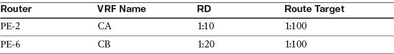
The IP vrf and VRF definition commands can be used to create a new VRF and enter the global configuration mode for the configured VRF. The name of the VRF is locally significant and is case sensitive. In MPLS L3/VPNs, the VRF is not operational unless the RD is defined.
VRFs are locally significant, and you need to advertise CA’s prefixes over the cloud to CB. If VRFs are locally significant, then how do we distinguish CA’s prefixes from CB’s prefixes once they get on the cloud?
Well, we have route distinguishers (RDs) for that purpose. What are route distinguishers?
An RD is a 64-bit value that is concatenated to the customer routes to keep the customer routes unique when MP-BGP carries them from one PE to another.
The format of an RD is “32 bits: 32 bits.” Typically the first 32 bits identify the AS number of the customer, but there is no standard.
Let’s configure the VRFs and the RDs:
On R2:
R2(config)# vrf definition CA
R2(config-vrf)# rd 1:10
On R6:
R6(config)# vrf definition CB
R6(config-vrf)# rd 1:20
VRFs are locally significant, and the RDs will keep the CE routes unique within the cloud. Once the PE router receives the VPNv4 routes, it strips off the 64-bit RD value. The question is, how does the receiving PE router know which VRF it should inject the routes into? The answer is, the route target.
Route targets, or RTs, are extended BGP communities that indicate which routes should be exported from the VRF into the MP-BGP and which routes should be imported from the MP-BGP into a given VRF. RTs are attached to the VPNv4 routes.
You need to remember that when BGP communities are involved, you need to manually configure the communities to be sent; otherwise, they will not be sent.
The route-target export command specifies an RT that is to be attached to every route exported from the local VRF into the MP-BGP. By contrast, the route-target import command specifies an RT to be used as an import filter; only routes matching the RT are imported into the VRF.
This implementation allows a route to have many imported or exported RTs, all to be attached to every imported or exported route.
The following configuration attaches an RT of 1:100 to all exported routes, and the import command instructs the PE router to import any VPNv4 route that carries an RT of 1:100:
On R2:
R2(config)# vrf definition CA
R2(config-vrf)# address-family ipv4
R2(config-vrf-af)# route-target export 1:100
R2(config-vrf-af)# route-target import 1:100
In the following configuration, the both keyword is used to replace both the import and export keywords:
On R6:
R6(config)# vrf definition CB
R6(config-vrf)# address-family ipv4
R6(config-vrf-af)# route-target both 1:100
The route targets are BGP extended communities that are attached to the VPNv4 addresses. Remember that communities are not sent unless they are configured to be sent. Let’s configure the PE routers to send the extended communities:
On R2:
R2(config)# router bgp 100
R2(config-router)# address-family vpnv4 unicast
R2(config-router-af)# neighbor 6.6.6.6 send-community extended
On R6:
R6(config)# router bgp 100
R6(config-router)# address-family vpnv4 unicast
R6(config-router-af)# neighbor 2.2.2.2 send-community extended
Note In some IOS versions, the neighbor x.x.x.x send-community extended command may be automatically configured, but it is a good practice to make a point to configure it, just in case your IOS version in the lab does not auto-configure this command for you, or the command was removed for troubleshooting purposes.
Let’s verify the VRF configuration:
On R2:
R2# show vrf
Name Default RD Protocols Interfaces
CA 1:10 ipv4
Think of VRFs as VLANs; once a VLAN is configured, the appropriate interfaces are assigned to that VLAN. The same philosophy applies to VRFs, which are Layer 3 VLANs. In this case, the VRFs are configured, and now the appropriate interfaces need to be assigned to that VRF. The following commands associate the f0/0 interface facing the customer to the VRF CA:
On R2:
R2(config)# interface FastEthernet0/0
R2(config-if)# vrf forwarding CA
The preceding command associates an interface with the specified VRF. When this command is applied to a given interface, the IP address of that interface is removed and it should be reconfigured.
You should see the following console message:
% Interface FastEthernet0/0 IPv4 disabled and address(es) removed due to enabling VRF CA
R2(config-if)# ip address 12.1.1.2 255.255.255.0
On R6:
R6(config)# interface FastEthernet0/0
R6(config-if)# vrf forwarding CB
R6(config-if)# ip address 67.1.1.6 255.255.255.0
Let’s verify the configuration:
On R2:
R2# show vrf detail
VRF CA (VRF Id = 1); default RD 1:10; default VPNID <not set>
Interfaces:
Fa0/0
Address family ipv4 (Table ID = 1 (0x1)):
Export VPN route-target communities
RT:1:100
Import VPN route-target communities
RT:1:100
No import route-map
No export route-map
VRF label distribution protocol: not configured
VRF label allocation mode: per-prefix
Address family ipv6 not active
The preceding output begins with the name of the VRF, the configured route distinguisher value, and the VPNID, which is normally not set by default. The VPNID is an extension used to further identify the VPN by using the customer OUI and VPN index, which can be keyed in as a hexadecimal- or decimal-formatted number.
The interfaces that have the VRF CA applied will be listed under the Interfaces column. It is a good practice to have at least one route target that the router will both export and import.
On R6:
R6# show ip vrf CB
Name Default RD Interfaces
CB 1:20 Fa0/0
R6# show ip vrf interfaces
Interface IP-Address VRF Protocol
Fa0/0 67.1.1.6 CB up
The following command will give you the same information:
R6# show vrf ipv4 interfaces
Interface VRF Protocol Address
Fa0/0 CB up 67.1.1.6
Let’s verify the connectivity between the PEs and CEs:
On R2:
R2# ping 12.1.1.1
Type escape sequence to abort.
Sending 5, 100-byte ICMP Echos to 12.1.1.1, timeout is 2 seconds:
.....
Success rate is 0 percent (0/5)
A regular ping will no longer work. A ping command with no other keywords will default to using the global routing table. The 12.1.1.0/24 prefix is not accessible in the global routing table anymore. The ping must be added with the proper VRF keyword. Remember the IP address is in the VRF and not the global routing table.
R2# ping vrf CA 12.1.1.1
Type escape sequence to abort.
Sending 5, 100-byte ICMP Echos to 12.1.1.1, timeout is 2 seconds:
.!!!!
Success rate is 80 percent (4/5), round-trip min/avg/max = 1/1/1 ms
On R6:
R6# ping vrf CB 67.1.1.7
Type escape sequence to abort.
Sending 5, 100-byte ICMP Echos to 67.1.1.7, timeout is 2 seconds:
.!!!!
Success rate is 80 percent (4/5), round-trip min/avg/max = 1/1/4 ms
Task 6
Configure RIPv2 between R1 and PE-2 and between R7 and PE-6. The customer routers (R1 and R7) should advertise their lo0 interfaces in this routing domain. Disable auto-summary. If this configuration is performed successfully, the CE routers (R1 and R7) should have reachability to each other’s routes.
On R1:
R1(config)# router rip
R1(config-router)# no auto-summary
R1(config-router)# version 2
R1(config-router)# network 1.0.0.0
R1(config-router)# network 12.0.0.0
On RE-2:
R2(config)# router rip
R2(config-router)# no auto-summary
R2(config-router)# version 2
R2(config-router)# address-family ipv4 vrf CA
R2(config-router-af)# network 12.0.0.0
Let’s verify the configuration:
On PE-2:
R2# show ip route vrf CA rip | begin Gate
Gateway of last resort is not set
1.0.0.0/24 is subnetted, 1 subnets
R 1.1.1.0 [120/1] via 12.1.1.1, 00:00:18, FastEthernet0/0
Let’s configure PE-6 and R7:
On R7:
R7(config)# router rip
R7(config-router)# no auto-summary
R7(config-router)# version 2
R7(config-router)# network 7.0.0.0
R7(config-router)# network 67.0.0.0
On PE-6:
R6(config)# router rip
R6(config-router)# no auto-summary
R6(config-router)# version 2
R6(config-router)# address-family ipv4 vrf CB
R6(config-router-af)# network 67.0.0.0
Let’s verify the configuration:
On PE-6:
R6# show ip route vrf CB rip | begin Gate
Gateway of last resort is not set
7.0.0.0/24 is subnetted, 1 subnets
R 7.7.7.0 [120/1] via 67.1.1.7, 00:00:13, FastEthernet0/0
In the last step of this task, the RIP routes should be redistributed into BGP so the neighboring PE router can see the routes in its BGP table. This redistribution should be done under another address family called “IPv4 unicast” in BGP. In some IOS releases, this address family is created automatically when the VRF, RD, and RTs are configured. But once again, you should never depend on the defaults.
Once you get to this final step, you should perform redistribution in one direction and verify each step of the way and then do the redistribution in the opposite direction. Let’s start with PE-2:
On PE-2:
R2(config)# router bgp 100
R2(config-router)# address-family ipv4 vrf CA
R2(config-router-af)# redistribute rip
Let’s verify the configuration:
R2# show bgp vpnv4 unicast all | begin Network
Network Next Hop Metric LocPrf Weight Path
Route Distinguisher: 1:10 (default for vrf CA)
*> 1.1.1.0/24 12.1.1.1 1 32768 ?
*> 12.1.1.0/24 0.0.0.0 0 32768 ?
Because the prefixes are in BGP as VPNv4 prefixes, PE-6 should also see these routes. Let’s verify:
On PE-6:
R6# show bgp vpnv4 unicast all | begin Network
Network Next Hop Metric LocPrf Weight Path
Route Distinguisher: 1:10
*>i1.1.1.0/24 2.2.2.2 1 100 0 ?
*>i12.1.1.0/24 2.2.2.2 0 100 0 ?
Route Distinguisher: 1:20 (default for vrf CB)
*>i1.1.1.0/24 2.2.2.2 1 100 0 ?
*>i12.1.1.0/24 2.2.2.2 0 100 0 ?
You can see the routes advertised by R1 on PE-6, so let’s redistribute these routes into RIP and verify:
R6(config)# router rip
R6(config-router)# address-family ipv4 vrf CB
R6(config-router-af)# redistribute bgp 100 metric 1
Let’s verify the configuration on R7, the customer router:
On R7:
R7# show ip route rip | begin Gate
Gateway of last resort is not set
1.0.0.0/24 is subnetted, 1 subnets
R 1.1.1.0 [120/1] via 67.1.1.6, 00:00:02, GigabitEthernet0/0
12.0.0.0/24 is subnetted, 1 subnets
R 12.1.1.0 [120/1] via 67.1.1.6, 00:00:02, GigabitEthernet0/0
To test this configuration, you need to enable debug ip icmp on R1 and generate a ping to 1.1.1.1 from R7. If this configuration is done correctly, you should see the ICMP-ECHO packets on R1.
Note The ping on R7 will fail because the redistribution is performed in one direction only, meaning that R1 doesn’t have a return route.
On R1:
R1# debug ip icmp
ICMP packet debugging is on
On R7:
R7# ping 1.1.1.1 repeat 2
Type escape sequence to abort.
Sending 2, 100-byte ICMP Echos to 1.1.1.1, timeout is 2 seconds:
..
Success rate is 0 percent (0/2)
Let’s see if R1 can see the ICMP echos generated by R7:
On R1:
ICMP: echo reply sent, src 1.1.1.1, dst 67.1.1.7, topology BASE, dscp 0 topoid 0
ICMP: echo reply sent, src 1.1.1.1, dst 67.1.1.7, topology BASE, dscp 0 topoid 0
Now you know the redistribution is working in one direction. You should configure the redistribution in the opposite direction:
On PE-6:
R6(config)# router bgp 100
R6(config-router)# address-family ipv4 vrf CB
R6(config-router-af)# redistribute rip
Let’s verify the configuration:
R6# show bgp vpnv4 unicast all | begin Network
Network Next Hop Metric LocPrf Weight Path
Route Distinguisher: 1:10
*>i1.1.1.0/24 2.2.2.2 1 100 0 ?
*>i12.1.1.0/24 2.2.2.2 0 100 0 ?
Route Distinguisher: 1:20 (default for vrf CB)
*>i1.1.1.0/24 2.2.2.2 1 100 0 ?
*> 7.7.7.0/24 67.1.1.7 1 32768 ?
*>i12.1.1.0/24 2.2.2.2 0 100 0 ?
*> 67.1.1.0/24 0.0.0.0 0 32768 ?
One of the reasons to use different route distinguishers for all VRFs in the network is clarity, especially when trying to figure out which VPN a route belongs to and where it originated. As you can see, the 1:20 RD is local, but the 1.1.1.0/24 network is present in both RDs, which means that the 1.1.1.0/24 network is participating in the same VPN.
You should see the prefixes on PE-2:
On PE-2:
R2# show bgp vpnv4 unicast all | begin Network
Network Next Hop Metric LocPrf Weight Path
Route Distinguisher: 1:10 (default for vrf CA)
*> 1.1.1.0/24 12.1.1.1 1 32768 ?
*>i7.7.7.0/24 6.6.6.6 1 100 0 ?
*> 12.1.1.0/24 0.0.0.0 0 32768 ?
*>i67.1.1.0/24 6.6.6.6 0 100 0 ?
Route Distinguisher: 1:20
*>i7.7.7.0/24 6.6.6.6 1 100 0 ?
*>i67.1.1.0/24 6.6.6.6 0 100 0 ?
Sure enough, you can see the routes. Now you must redistribute BGP into RIP so R1 can see R7’s prefixes:
R2(config)# router rip
R2(config-router)# address-family ipv4 vrf CA
R2(config-router-af)# redistribute bgp 100 metric 1
Let’s verify the configuration:
On R1:
R1# show ip route rip | begin Gate
Gateway of last resort is not set
7.0.0.0/24 is subnetted, 1 subnets
R 7.7.7.0 [120/1] via 12.1.1.2, 00:00:20, FastEthernet0/0
67.0.0.0/24 is subnetted, 1 subnets
R 67.1.1.0 [120/1] via 12.1.1.2, 00:00:20, FastEthernet0/0
Now let’s test and verify the configuration:
On R1:
R1# ping 7.7.7.7
Type escape sequence to abort.
Sending 5, 100-byte ICMP Echos to 7.7.7.7, timeout is 2 seconds:
!!!!!
Success rate is 100 percent (5/5), round-trip min/avg/max = 120/122/124 ms
R6# show bgp vpnv4 unicast vrf CB 1.1.1.0
BGP routing table entry for 1:20:1.1.1.0/24, version 4
Paths: (1 available, best # 1, table CB) VPNv4 address
Not advertised to any peer
Local, imported path from 1:10:1.1.1.0/24
2.2.2.2 (metric 3125) from 2.2.2.2 (2.2.2.2)
Origin incomplete, metric 1, localpref 100, valid, internal, best
Extended Community: RT:1:100
mpls labels in/out nolabel/207
In the output of the preceding show command, you can see that the route was imported with a VPNv4 address of 1:10:1.1.1.0/24 and an extended community of RT:1:100. If the local router receives an unlabeled packet destined for network 1.1.1.0/24, the local LSR will impose label 207, which is the VPN label, and send it to 2.2.2.2.
Let’s see the LFIB for this network:
R6# show mpls forwarding-table vrf CB 1.1.1.0
Local Outgoing Prefix Bytes Label Outgoing Next Hop
Label Label or Tunnel Id Switched interface
None 207 1.1.1.0/24[V] 0 Se1/5 point2point
The output of the preceding show command reveals that when a packet comes in with no label, it will go out with label 207, and the outgoing interface is S1/5.
The output of the following command shows that the next hop to reach network 1.1.1.0/24 is 2.2.2.2. You can also see that the route was redistributed correctly with an RD of 1:10 to 1:20:
R6# show bgp vpnv4 unicast all | begin Network
Network Next Hop Metric LocPrf Weight Path
Route Distinguisher: 1:10
*>i1.1.1.0/24 2.2.2.2 1 100 0 ?
*>i12.1.1.0/24 2.2.2.2 0 100 0 ?
Route Distinguisher: 1:20 (default for vrf CB)
*>i1.1.1.0/24 2.2.2.2 1 100 0 ?
*> 7.7.7.0/24 67.1.1.7 1 32768 ?
*>i12.1.1.0/24 2.2.2.2 0 100 0 ?
*> 67.1.1.0/24 0.0.0.0 0 32768 ?
Let’s see how the local router reaches 2.2.2.2:
R6# show mpls forwarding-table 2.2.2.2
Local Outgoing Prefix Bytes Label Outgoing Next Hop
Label Label or Tunnel Id Switched interface
600 500 2.2.2.2/32 0 Se1/5 point2point
You can see that PE-6 (the PE router) will assign label 500, and it’ll send it out of its S1/5 interface. This label is not the VPN label; it is the IPv4 label or the top label, and the top label will be swapped from one “P” LSR to another “P” LSR. Therefore, R6 will assign a bottom label of 207 (the VPN label) and a top label of 502 (the IPv4 label). Let’s verify this on R6’s CEF table:
R6# show ip cef vrf CB 1.1.1.0
1.1.1.0/24
nexthop 56.1.1.5 Serial1/5 label 500 207
Sure enough, the top label that gets swapped from one LSR to another is label 500; this label was advertised to the local router by R5. The second label, or the bottommost label, is label 207, and this label was imposed by PE-2—to be more specific, by the MP-BGP process running on PE-2. This is called the VPN label. Let’s move a little closer.
If the local LSR receives a labeled packet with the top label of 500, it will swap that label with 400 and send it out of its S1/4 interface toward R4:
On R5:
R5# show mpls for 2.2.2.2 32
Local Outgoing Prefix Bytes Label Outgoing Next Hop
Label Label or Tunnel Id Switched interface
500 400 2.2.2.2/32 88737 Se1/4 point2point
If the local LSR receives a labeled packet with the top label of 400, it will swap that label with 300 and send it out of its S1/3 interface toward R3:
On R4:
R4# show mpls for 2.2.2.2 32
Local Outgoing Prefix Bytes Label Outgoing Next Hop
Label Label or Tunnel Id Switched interface
400 300 2.2.2.2/32 88919 Se1/3 point2point
If the local LSR (R3) receives a labeled packet with the top label of 300, it will pop that label and send it out of its S1/2 interface toward R2:
On R3:
R3# show mpls for 2.2.2.2 32
Local Outgoing Prefix Bytes Label Outgoing Next Hop
Label Label or Tunnel Id Switched interface
300 Pop Label 2.2.2.2/32 82942 Se1/2 point2point
R2 receives the packet with only one label—that’s label 207, or the VPN label. Let’s see what action this LSR takes when it receives the labeled packet:
On R2:
R2# show mpls for 2.2.2.2 32
Local Outgoing Prefix Bytes Label Outgoing Next Hop
Label Label or Tunnel Id Switched interface
None No Label 2.2.2.2/32 0 aggr-punt
R2# show ip cef vrf CA 1.1.1.0
1.1.1.0/24
nexthop 12.1.1.1 FastEthernet0/0
R2# show ip route vrf CA 1.1.1.0
Routing Table: CA
Routing entry for 1.1.1.0/24
Known via "rip", distance 120, metric 1
Redistributing via bgp 100, rip
Advertised by bgp 100
Last update from 12.1.1.1 on FastEthernet0/0, 00:00:22 ago
Routing Descriptor Blocks:
* 12.1.1.1, from 12.1.1.1, 00:00:22 ago, via FastEthernet0/0
Route metric is 1, traffic share count is 1
The output of the following show command reveals what the local router does before it sends the packet to R1. If R2 sees label 207 coming in, it will send the packet out with no labels whatsoever and send it to 12.1.1.1:
R2# show bgp vpnv4 unicast vrf CA labels
Network Next Hop In label/Out label
Route Distinguisher: 1:10 (CA)
1.1.1.0/24 12.1.1.1 207/nolabel
7.7.7.0/24 6.6.6.6 nolabel/607
12.1.1.0/24 0.0.0.0 208/nolabel(CA)
67.1.1.0/24 6.6.6.6 nolabel/608
Let’s see how the labels are imposed, swapped, and popped:
On R7:
R7# traceroute 1.1.1.1 numeric
Type escape sequence to abort.
Tracing the route to 1.1.1.1
VRF info: (vrf in name/id, vrf out name/id)
1 67.1.1.6 0 msec 0 msec 4 msec
2 56.1.1.5 [MPLS: Labels 500/207 Exp 0] 176 msec 180 msec 184 msec
3 45.1.1.4 [MPLS: Labels 400/207 Exp 0] 160 msec 164 msec 160 msec
4 34.1.1.3 [MPLS: Labels 300/207 Exp 0] 148 msec 144 msec 144 msec
5 12.1.1.2 [MPLS: Label 207 Exp 0] 128 msec 128 msec 128 msec
6 12.1.1.1 76 msec * 72 msec
![]() First line: The packet is sent to the next-hop router with an IP address of 67.1.1.6; this is router R6.
First line: The packet is sent to the next-hop router with an IP address of 67.1.1.6; this is router R6.
![]() Second line: When PE-6 receives the packet destined to 1.1.1.1, it looks up its LFIB and assigns label 207, which is the VPN label. Then it realizes that the next hop is 2.2.2.2, its peer neighbor—but the question is, what label should it assign that will forward the packet toward 2.2.2.2? The answer is 500. Therefore, R6 assigns the second label, or the IPv4 label of 500, and sends it to R5 (56.1.1.5).
Second line: When PE-6 receives the packet destined to 1.1.1.1, it looks up its LFIB and assigns label 207, which is the VPN label. Then it realizes that the next hop is 2.2.2.2, its peer neighbor—but the question is, what label should it assign that will forward the packet toward 2.2.2.2? The answer is 500. Therefore, R6 assigns the second label, or the IPv4 label of 500, and sends it to R5 (56.1.1.5).
![]() Third line: R5 swaps the top label with 400 and sends it to R4 with an IP address of 45.1.1.4.
Third line: R5 swaps the top label with 400 and sends it to R4 with an IP address of 45.1.1.4.
![]() Fourth line: R4 swaps the top label with 300 and sends it to R3 with an IP address of 34.1.1.3.
Fourth line: R4 swaps the top label with 300 and sends it to R3 with an IP address of 34.1.1.3.
![]() Fifth line: Because R3 is the penultimate hop popper (PHP), it pops the top label (300) and forwards the packet as a labeled packet with a VPN label of 207 and sends the labeled packet to R2.
Fifth line: Because R3 is the penultimate hop popper (PHP), it pops the top label (300) and forwards the packet as a labeled packet with a VPN label of 207 and sends the labeled packet to R2.
![]() Sixth line: R2 pops the VPN label and sends the packet with no labels to R1 with an IP address of 12.1.1.1.
Sixth line: R2 pops the VPN label and sends the packet with no labels to R1 with an IP address of 12.1.1.1.
We need to take a closer look at the control plane process happening here.
Table 15-3 shows how each LSR will assign a label for R2’s 2.2.2.2 locally.
Table 15-3 LSR Label Assignments for R2

Once the labels are assigned locally, they are advertised to their neighboring LDP peer, as shown in Table 15-4.
Table 15-4 Advertising Labels to the Neighboring LDP Peer
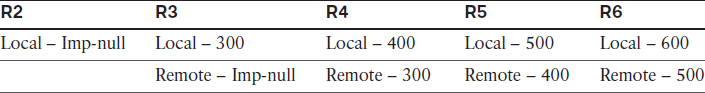
Therefore, if R6 needs to connect to 2.2.2.2, it has to impose label 500 and send it to R5:
![]() R5 swaps label 500 with 400 and sends it to R4.
R5 swaps label 500 with 400 and sends it to R4.
![]() R4 swaps label 400 with 300 and sends it to R3.
R4 swaps label 400 with 300 and sends it to R3.
![]() R3 pops label 300, and the packet is sent to R2.
R3 pops label 300, and the packet is sent to R2.
When R2 receives a routing update from R1 (customer router), it assigns label 207, an RD and an RT, and sends them to R6, as outlined in Table 15-5.
Table 15-5 Packet Label Assignment
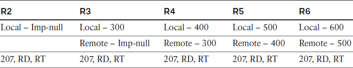
![]() Now R6 knows which label (207 in this case) it has to assign to reach 1.1.1.0/24.
Now R6 knows which label (207 in this case) it has to assign to reach 1.1.1.0/24.
![]() R7 (the customer) pings R1 and sends the IP packet to the next-hop IP address of 67.1.1.6 or R6.
R7 (the customer) pings R1 and sends the IP packet to the next-hop IP address of 67.1.1.6 or R6.
![]() R6 receives the unlabeled packet destined to 1.1.1.1 with a next-hop IP address of 2.2.2.2.
R6 receives the unlabeled packet destined to 1.1.1.1 with a next-hop IP address of 2.2.2.2.
![]() R6 assigns label 207 (the VPN label that R6 received from R2), an RD, and an RT and then realizes that this needs to be sent to 2.2.2.2 (R2). R6 assigns label 207 to reach 1.1.1.0/24.
R6 assigns label 207 (the VPN label that R6 received from R2), an RD, and an RT and then realizes that this needs to be sent to 2.2.2.2 (R2). R6 assigns label 207 to reach 1.1.1.0/24.
![]() R6 assigns the second label of 500 (the IPv4 label to reach 2.2.2.2) and sends the labeled packet to R5.
R6 assigns the second label of 500 (the IPv4 label to reach 2.2.2.2) and sends the labeled packet to R5.
![]() R5 only looks at the top label and swaps the top label of 500 with 400 and sends it to R4.
R5 only looks at the top label and swaps the top label of 500 with 400 and sends it to R4.
![]() R4 receives a labeled packet. It swaps label 400 with 300 and sends it to R3.
R4 receives a labeled packet. It swaps label 400 with 300 and sends it to R3.
![]() R3 receives label 300. It pops the label and sends the labeled packet to R2.
R3 receives label 300. It pops the label and sends the labeled packet to R2.
![]() R2 receives a labeled packet. It removes the RD and then checks its BGP configuration to see which VRF is importing that particular RT. Once it finds this, it pops the RT and label 207 and sends the IP packet to the customer.
R2 receives a labeled packet. It removes the RD and then checks its BGP configuration to see which VRF is importing that particular RT. Once it finds this, it pops the RT and label 207 and sends the IP packet to the customer.
It is very important to have a process that you can follow. The following outlines the process:
1. Configure and verify the topology: This is where you ping the directly connected router and verify the IP addresses and the loopback interfaces, as well as verify that CEF is running.
2. Configure OSPF in the core: This provides reachability within the core. I recommend agreeing on a process identifier (I use PID 1) when configuring OSPF on the core routers. What if the IGP between the CE and the PE routers is also OSPF? In that case, a PID of 2 is what I use for that purpose. In this step, you should run OSPF on only the links and the loopback interfaces within the core.
3. Configure LDP and verify neighbor adjacency: Label distribution protocol is one way that you can exchange information regarding label assignment. In this lab, we will rely on it to translate all relevant label information between MPLS-enabled devices.
4. Configure BGP: In this step, you should pay close attention to the task. If the task states that only VPNv4 routes should be exchanged, which loopback interface should be used as the source of BGP updates?
5. Configure VRFs: The VRFs, RD, and RTs are configured. Ensure that the RTs match on both PEs; otherwise, the customers will not see each other’s routes. Assign the interface that connects the PE to the CE in the VRF. Names are always case sensitive. You must go back to BGP and activate the neighboring PE in the address family for VPNv4.
6. Configure routing between the CE and the PE routers: Ordinarily, organizations run static routing between their sites and the service provider, but routing protocols can also be used. We will explore all the routing options mentioned in the blueprint.
7. Redistribution: Always redistribute in one direction and verify before redistributing in the opposite direction.
The preceding list is not detailed, and you should create your own process in a detailed manner. Once you come up with your own process, you should configure MPLS/L3VPNs using that process for both implemetation and troubleshooting.
Erase the startup configuration of these routers and reload them before proceeding to the next lab.
Lab 15-3: EIGRP Routing in a VPN
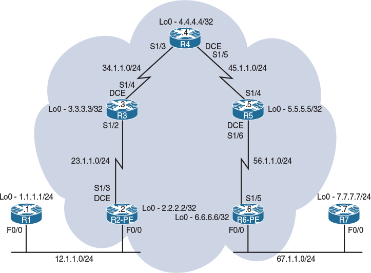
Figure 15-3 Configuring RIPv2 Routing in a VPN
Figure 15-3 illustrates the topology that will be used in the following tasks.
Task 1 through Task 5 of RIPv2 routing in Lab 15-2 are identical to the first five tasks in this lab. Therefore, repeat Tasks 1 through 5 before proceeding to the next task.
Task 6
Configure EIGRP between R1 and PE-2 and between R7 and PE-6. The customer routers (R1 and R7) should also run EIGRP on their lo0 interfaces. If this configuration is performed successfully, the CE routers (R1 and R7) should have reachability to each other’s routes. You should use EIGRP named mode when configuring EIGRP on R1 and R7. Use any AS number on the PE routers.
Let’s configure R1 and R2:
On R1:
R1(config)# router eigrp AS100
R1(config-router)# address-family ipv4 unicast as 100
R1(config-router-af)# network 1.1.1.1 0.0.0.0
R1(config-router-af)# network 12.1.1.1 0.0.0.0
On PE-2:
R2(config)# router eigrp 100
R2(config-router)# address-family ipv4 vrf CA
R2(config-router-af)# network 12.1.1.2 0.0.0.0
The autonomous-system command is mandatory and it must be configured, because the VRF configured under router eigrp 100 will not inherit the AS number from the global EIGRP process. Therefore, there are two options.
In IOS release 12 or earlier, the AS number was configured under the address family using the autonomous-system command. This command is hidden in Cisco’s IOS 15 code. Let’s verify:
R2(config)# router eigrp 100
R2(config-router)# address-family ipv4 vrf CA
R2(config-router-af)# network 12.1.1.2 0.0.0.0
R2(config-router-af)# ?
Address Family configuration commands:
auto-summary Enable automatic network number summarization
bfd BFD configuration commands
default Set a command to its defaults
default-information Control distribution of default information
default-metric Set metric of redistributed routes
distance Define an administrative distance
distribute-list Filter entries in eigrp updates
eigrp EIGRP specific commands
exit-address-family Exit Address Family configuration mode
help Description of the interactive help system
maximum-paths Forward packets over multiple paths
maximum-prefix Maximum number of prefixes acceptable in aggregate
metric Modify metrics and parameters for advertisement
neighbor Specify a neighbor router
network Enable routing on an IP network
no Negate a command or set its defaults
offset-list Add or subtract offset from EIGRP metrics
passive-interface Suppress routing updates on an interface
redistribute Redistribute IPv4 routes from another routing protocol
shutdown Shutdown address family
summary-metric Specify summary to apply metric/filtering
timers Adjust routing timers
traffic-share How to compute traffic share over alternate paths
variance Control load balancing variance
Even though the command is hidden, it can be configured; the Tab key cannot be used to complete the command, but you don’t have to configure every letter. Let’s verify:
R2(config-router-af)# autonomous-system 100
You should see the following console message:
DUAL-5-NBRCHANGE: EIGRP-IPv4 100: Neighbor 12.1.1.1 (FastEthernet0/0) is up:
new adjacency
The AS number can also be configured as part of the address-family command. Let’s configure and verify. But first, let’s remove EIGRP and reconfigure it:
R2(config)# no router eigrp 100
R2(config)# router eigrp 100
R2(config-router)# address-family ipv4 vrf CA ?
autonomous-system Specify Address-Family Autonomous System Number
R2(config-router)# address-family ipv4 vrf CA autonomous-system 100
R2(config-router-af)# network 12.1.1.2 0.0.0.0
You should get the following console message:
%DUAL-5-NBRCHANGE: EIGRP-IPv4 100: Neighbor 12.1.1.1 (FastEthernet0/0) is up:
new adjacency
Let’s verify the configuration:
On PE-2:
R2# show ip route vrf CA eigrp | begin Gate
Gateway of last resort is not set
1.0.0.0/24 is subnetted, 1 subnets
D 1.1.1.0 [90/156160] via 12.1.1.1, 00:02:35, FastEthernet0/0
Let’s configure PE-6 and R7:
R6(config)# router eigrp 100
R6(config-router)# address-family ipv4 vrf CB autonomous-system 100
R6(config-router-af)# network 67.1.1.6 0.0.0.0
On R7:
R7(config)# router eigrp AS100
R7(config-router)# address-family ipv4 unicast autonomous-system 100
R7(config-router-af)# network 7.7.7.7 0.0.0.0
R7(config-router-af)# network 67.1.1.7 0.0.0.0
You should see the following console message:
%DUAL-5-NBRCHANGE: EIGRP-IPv4 100: Neighbor 67.1.1.7 (FastEthernet0/0) is up:
new adjacency
Let’s verify the configuration:
On PE-6:
R6# show ip route vrf CB eigrp | begin Gate
Gateway of last resort is not set
7.0.0.0/24 is subnetted, 1 subnets
D 7.7.7.0 [90/28192] via 67.1.1.7, 00:00:52, FastEthernet0/0
The final step is to perform the route redistribution:
On PE-2:
R2(config)# router bgp 100
R2(config-router)# address-family ipv4 vrf CA
R2(config-router-af)# redistribute eigrp 100
Let’s verify the configuration:
R2# show bgp vpnv4 unicast all | begin Network
Network Next Hop Metric LocPrf Weight Path
Route Distinguisher: 1:10 (default for vrf CA)
*> 1.1.1.0/24 12.1.1.1 156160 32768 ?
*> 12.1.1.0/24 0.0.0.0 0 32768 ?
Let’s verify this configuration on PE-6:
On PE-6:
R6# show bgp vpnv4 unicast all | begin Network
Network Next Hop Metric LocPrf Weight Path
Route Distinguisher: 1:10
*>i1.1.1.0/24 2.2.2.2 156160 100 0 ?
*>i12.1.1.0/24 2.2.2.2 0 100 0 ?
Route Distinguisher: 1:20 (default for vrf CB)
*>i1.1.1.0/24 2.2.2.2 156160 100 0 ?
*>i12.1.1.0/24 2.2.2.2 0 100 0 ?
Now you need to redistribute BGP into EIGRP so that R7 (the customer router) can see the routes from R1:
R6(config)# router eigrp 100
R6(config-router)# address-family ipv4 vrf CB
R6(config-router-af)# redistribute bgp 100 metric 1 1 1 1 1
Let’s verify the configuration:
On R7:
R7# show ip route eigrp | begin Gate
Gateway of last resort is not set
1.0.0.0/24 is subnetted, 1 subnets
D 1.1.1.0 [90/2713600] via 67.1.1.6, 00:00:34, GigabitEthernet0/0
12.0.0.0/24 is subnetted, 1 subnets
D 12.1.1.0 [90/153600] via 67.1.1.6, 00:00:34, GigabitEthernet0/0
Now you need to perform redistribution going in the opposite direction:
On PE-6:
R6(config)# router bgp 100
R6(config-router)# address-family ipv4 vrf CB
R6(config-router-af)# redistribute eigrp 100
Now we will make the necessary configuration on R2 which is acting as a Provider Edge device.
On PE-2:
R2(config)# router eigrp 100
R2(config-router)# address-family ipv4 vrf CA
R2(config-router-af)# redistribute bgp 100 metric 1 1 1 1 1
We need to confirm that we have formed EIGRP adjacencies.
On R1:
R1# show ip route eigrp | begin Gate
Gateway of last resort is not set
7.0.0.0/24 is subnetted, 1 subnets
D 7.7.7.0 [90/30752] via 12.1.1.2, 00:00:28, FastEthernet0/0
67.0.0.0/24 is subnetted, 1 subnets
D 67.1.1.0 [90/30720] via 12.1.1.2, 00:00:28, FastEthernet0/0
Let’s test the configuration:
On R1:
R1# ping 7.7.7.7
Type escape sequence to abort.
Sending 5, 100-byte ICMP Echos to 7.7.7.7, timeout is 2 seconds:
!!!!!
Success rate is 100 percent (5/5), round-trip min/avg/max = 120/121/124 ms
R1# ping 7.7.7.7 source loopback0
Type escape sequence to abort.
Sending 5, 100-byte ICMP Echos to 7.7.7.7, timeout is 2 seconds:
Packet sent with a source address of 1.1.1.1
!!!!!
Success rate is 100 percent (5/5), round-trip min/avg/max = 120/121/124 ms
Erase the startup configuration of these routers and reload them before proceeding to the next lab.
Lab 15-4: OSPF Routing in a VPN
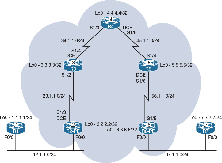
Figure 15-4 Configuring RIPv2 Routing in a VPN
Figure 15-4 illustrates the topology that will be used in the following tasks.
Task 1 through Task 5 of Lab 15-2 are identical to the first five tasks in this lab. Therefore, repeat Tasks 1 through 5 before proceeding to the next task.
Task 6
Configure the CEs (R1 and R7) with a VRF service that incorporates OSPF as the routing protocol. PE-2 should use an OSPF process ID of 2, whereas PE-6 should use a PID of 6 to accomplish this task.
![]() R1 should use an OSPF RID of 0.0.0.1, and R7 should use an OSPF RID of 0.0.0.7.
R1 should use an OSPF RID of 0.0.0.1, and R7 should use an OSPF RID of 0.0.0.7.
![]() R1 and R7 should be configured in Area 0 on all their directly connected interfaces, and they should see each other’s routes as intra-area OSPF routes. The loopback interfaces of R1 and R7 should be advertised with their correct mask.
R1 and R7 should be configured in Area 0 on all their directly connected interfaces, and they should see each other’s routes as intra-area OSPF routes. The loopback interfaces of R1 and R7 should be advertised with their correct mask.
Let’s start by configuring OSPF on R1 and PE-2:
On R1:
R1(config)# interface loopback0
R1(config-if)# ip ospf network point-to-point
R1(config)# router ospf 1
R1(config-router)# router-id 0.0.0.1
R1(config-router)# network 1.1.1.1 0.0.0.0 area 1
R1(config-router)# network 12.1.1.1 0.0.0.0 area 1
On PE-2:
R2(config)# router ospf 2 vrf CA
R2(config-router)# network 12.1.1.2 0.0.0.0 area 0
You should see the following console message:
%OSPF-5-ADJCHG: Process 2, Nbr 0.0.0.1 on FastEthernet0/0 from LOADING to FULL,
Loading Done
Let’s verify the configuration:
On PE-2:
R2# show ip route vrf CA ospf | begin Gate
Gateway of last resort is not set
1.0.0.0/24 is subnetted, 1 subnets
O 1.1.1.0 [110/2] via 12.1.1.1, 00:01:43, FastEthernet0/0
Let’s configure OSPF on PE-6 and R7:
On R7:
R7(config)# interface loopback0
R7(config-if)# ip ospf network point-to-point
R7(config)# router ospf 1
R7(config-router)# router-id 0.0.0.7
R7(config-router)# network 7.7.7.7 0.0.0.0 area 0
R7(config-router)# network 67.1.1.7 0.0.0.0 area 0
On PE-6:
R7(config)# router ospf 6 vrf CB
R7(config-router)# network 67.1.1.6 0.0.0.0 area 0
You should see the following console message:
%OSPF-5-ADJCHG: Process 6, Nbr 0.0.0.7 on FastEthernet0/0 from LOADING to FULL,
Loading Done
Let’s verify the configuration:
On PE-6:
R6# show ip route vrf CB ospf | begin Gate
Gateway of last resort is not set
7.0.0.0/24 is subnetted, 1 subnets
O 7.7.7.0 [110/2] via 67.1.1.7, 00:01:34, FastEthernet0/0
So far you can see that the CE and PE routers are successfully exchanging routes. The next step is to perform the redistribution. You should do this in one direction first and then perform redistribution in the opposite direction. Let’s start with PE-2:
On PE-2:
R2(config)# router bgp 100
R2(config-router)# address-family ipv4 vrf CA
R2(config-router-af)# redistribute ospf 2
Let’s verify the configuration:
R2# show bgp vpnv4 unicast all | begin Network
Network Next Hop Metric LocPrf Weight Path
Route Distinguisher: 1:10 (default for vrf CA)
*> 1.1.1.0/24 12.1.1.1 2 32768 ?
*> 12.1.1.0/24 0.0.0.0 0 32768 ?
This means that PE-6 should also have these prefixes in its BGP table. Let’s verify:
On PE-6:
R6# show bgp vpnv4 unicast all | begin Network
Network Next Hop Metric LocPrf Weight Path
Route Distinguisher: 1:10
*>i1.1.1.0/24 2.2.2.2 2 100 0 ?
*>i12.1.1.0/24 2.2.2.2 0 100 0 ?
Route Distinguisher: 1:20 (default for vrf CB)
*>i1.1.1.0/24 2.2.2.2 2 100 0 ?
*>i12.1.1.0/24 2.2.2.2 0 100 0 ?
To be more specific, you can also use the following show command:
R6# show bgp vpnv4 unicast vrf CB | begin Network
Network Next Hop Metric LocPrf Weight Path
Route Distinguisher: 1:20 (default for vrf CB)
*>i1.1.1.0/24 2.2.2.2 2 100 0 ?
*>i12.1.1.0/24 2.2.2.2 0 100 0 ?
Let’s redistribute the VPNv4 routes into OSPF so that R7 can see them:
R6(config)# router ospf 6 vrf CB
R6(config-router)# redistribute bgp 100 subnets
R7 should have these routes in its routing table. Let’s verify:
On R7:
R7# show ip route ospf | begin Gate
Gateway of last resort is not set
1.0.0.0/24 is subnetted, 1 subnets
O E2 1.1.1.0 [110/2] via 67.1.1.6, 00:00:15, GigabitEthernet0/0
12.0.0.0/24 is subnetted, 1 subnets
O E2 12.1.1.0 [110/1] via 67.1.1.6, 00:00:15, GigabitEthernet0/0
Well, this is good and bad news. The good news is that the redistribution has worked. The bad news is that the routes are showing up in the routing table of R7 as external type-2, or E2. Let’s perform the redistribution in the opposite direction and then find out why the routes are showing up as E2.
On PE-6:
R6(config)# router bgp 100
R6(config-router)# address-family ipv4 vrf CB
R6(config-router-af)# redistribute ospf 6
Let’s verify the configuration:
R6# show bgp vpnv4 unicast vrf CB | begin Network
Network Next Hop Metric LocPrf Weight Path
Route Distinguisher: 1:20 (default for vrf CB)
*>i1.1.1.0/24 2.2.2.2 2 100 0 ?
*> 7.7.7.0/24 67.1.1.7 2 32768 ?
*>i12.1.1.0/24 2.2.2.2 0 100 0 ?
*> 67.1.1.0/24 0.0.0.0 0 32768 ?
This means that PE-2 should have these prefixes in its BGP table:
On PE-2:
R2# show bgp vpnv4 unicast all | begin Network
Network Next Hop Metric LocPrf Weight Path
Route Distinguisher: 1:10 (default for vrf CA)
*> 1.1.1.0/24 12.1.1.1 2 32768 ?
*>i7.7.7.0/24 6.6.6.6 2 100 0 ?
*> 12.1.1.0/24 0.0.0.0 0 32768 ?
*>i67.1.1.0/24 6.6.6.6 0 100 0 ?
Route Distinguisher: 1:20
*>i7.7.7.0/24 6.6.6.6 2 100 0 ?
*>i67.1.1.0/24 6.6.6.6 0 100 0 ?
The output of the preceding show command reveals that 7.7.7.0/24 and 67.1.1.0/24 are in the BGP table of PE-2. Let’s redistribute BGP into OSPF so that R1 can see the routes advertised by R7:
R2(config)# router ospf 2 vrf CA
R2(config-router)# redistribute bgp 100 subnets
Let’s verify the configuration:
On R1:
R1# show ip route ospf | begin Gate
Gateway of last resort is not set
7.0.0.0/24 is subnetted, 1 subnets
O E2 7.7.7.0 [110/2] via 12.1.1.2, 00:00:21, FastEthernet0/0
67.0.0.0/24 is subnetted, 1 subnets
O E2 67.1.1.0 [110/1] via 12.1.1.2, 00:00:21, FastEthernet0/0
Sure enough, R1 can see the routes, but once again they are showing up as E2. Let’s test this configuration:
R1# ping 7.7.7.7
Type escape sequence to abort.
Sending 5, 100-byte ICMP Echos to 7.7.7.7, timeout is 2 seconds:
!!!!!
Success rate is 100 percent (5/5), round-trip min/avg/max = 120/120/124 ms
R1# ping 7.7.7.7 source loopback0
Type escape sequence to abort.
Sending 5, 100-byte ICMP Echos to 7.7.7.7, timeout is 2 seconds:
Packet sent with a source address of 1.1.1.1
!!!!!
Success rate is 100 percent (5/5), round-trip min/avg/max = 120/121/124 ms
Note All OSPF routes are showing up as external type-2. Was this because of the redistribution?
Although redistribution results in this behavior under normal circumstances, this does not follow classic OSPF default behavior. Let’s look at the reason behind the behavior:
On PE-2:
R2# show bgp vpnv4 unicast vrf CA 7.7.7.0 | include OSPF DOMAIN
Extended Community: RT:1:100 OSPF DOMAIN ID:0x0005:0x000000060200
Every domain ID on Cisco routers will begin with 0005, 0105, or 0205, which identifies the type of format used. With the 0005 value used, the next four octets are viewed as the global administrator field, and it’s used as part of the domain ID (in this case, 0x00000006). This value is highlighted in the preceding output.
The last two octets would be used as a local administrator field, which is ignored. This is the 0200 at the end of this domain ID. Let’s repeat the same show command on PE-6 for prefix 1.1.1.0/24:
On PE-6:
R6# show bgp vpnv4 unicast vrf CB 1.1.1.0 | include OSPF DOMAIN
Extended Community: RT:1:100 OSPF DOMAIN ID:0x0005:0x000000020200
As you can see, the domain IDs don’t match at all. Under normal OSPF design rules, the process ID of an OSPF router doesn’t need to match any other peer’s process ID. However, with MPLS, the router uses the OSPF process as a portion of the domain ID. Therefore, you must manually change the process ID to match on all sides of the cloud or statically configure a domain ID that matches on all routers.
Routers that do not share the same domain ID are considered external to OSPF. If the domain IDs match, the routes are considered type-3 LSAs.
Manually configuring the domain ID is preferred because this does not change the classic understanding of the process ID in OSPF. A clearing of BGP with clear ip bgp * in and clear ip bgp * out can be used to enforce the change faster.
Let’s change the domain IDs:
On PE-2:
R2(config)# router ospf 2 vrf CA
R2(config-router)# domain-id 0.0.0.1
On PE-6:
R6(config)# router ospf 6 vrf CB
R6(config-router)# domain-id 0.0.0.1
On PE-2 and PE-6:
Rx# clear ip bgp * in
Rx# clear ip bgp * out
Let’s verify the configuration:
On R1:
R1# show ip route ospf | begin Gate
Gateway of last resort is not set
7.0.0.0/24 is subnetted, 1 subnets
O IA 7.7.7.0 [110/3] via 12.1.1.2, 00:02:05, FastEthernet0/0
67.0.0.0/24 is subnetted, 1 subnets
O IA 67.1.1.0 [110/2] via 12.1.1.2, 00:02:05, FastEthernet0/0
On R7:
R7# show ip route ospf | begin Gate
Gateway of last resort is not set
1.0.0.0/24 is subnetted, 1 subnets
O IA 1.1.1.0 [110/3] via 67.1.1.6, 00:03:12, GigabitEthernet0/0
12.0.0.0/24 is subnetted, 1 subnets
O IA 12.1.1.0 [110/2] via 67.1.1.6, 00:03:12, GigabitEthernet0/0
This looks a little better, but why are the prefixes showing up as inter-area?
In an MPLS environment, the cloud is known as the MPLS VPN Backbone area or the Super Backbone area, and the PE routers are known as the ABRs. Therefore, the prefixes from one CE traversed through the Super Backbone into Backbone area, and this is the reason they are seen as inter-area routes on the other CE. Let’s look at the Super Backbone area:
On PE-2:
R2# show ip ospf 2 | include Super
Connected to MPLS VPN Superbackbone, VRF CA
There are two solutions to this problem:
![]() Solution 1: In this solution, a sham-link is configured, which is the preferred method. It’s the native solution to this problem. We will configure sham-link in the next lab.
Solution 1: In this solution, a sham-link is configured, which is the preferred method. It’s the native solution to this problem. We will configure sham-link in the next lab.
![]() Solution 2: In this solution, a GRE tunnel is configured.
Solution 2: In this solution, a GRE tunnel is configured.
In this lab, we configure a GRE tunnel. When a GRE tunnel is configured, you must remember the following two important points:
![]() The tunnel interface must be advertised in the area that the customer routes are configured in.
The tunnel interface must be advertised in the area that the customer routes are configured in.
![]() The tunnel interface must be configured in the customer’s VRF using the vrf forwarding or ip vrf forwarding command.
The tunnel interface must be configured in the customer’s VRF using the vrf forwarding or ip vrf forwarding command.
We are going to use the loopback0 interface of PE-2 as the source and the loopback0 interface of PE-6 as the destination of the tunnel. Remember that if the vrf forwarding command is entered after the IP address is configured, the IP address will be removed and it must be reconfigured.
R2(config)# interface tunnel 26
R2(config-if)# vrf forwarding CA
R2(config-if)# ip address 26.1.1.2 255.255.255.0
R2(config-if)# tunnel source loopback0
R2(config-if)# tunnel destination 6.6.6.6
R2(config)# router ospf 2 vrf CA
R2(config-router)# network 26.1.1.2 0.0.0.0 area 0
On PE-6:
R6(config)# interface tunnel 62
R6(config-if)# vrf forwarding CB
R6(config-if)# ip address 26.1.1.6 255.255.255.0
R6(config-if)# tunnel source loopback0
R6(config-if)# tunnel destination 2.2.2.2
R6(config)# router ospf 5 vrf CB
R6(config-router)# network 26.1.1.6 0.0.0.0 area 0
You should see the following console message:
%OSPF-5-ADJCHG: Process 6, Nbr 12.1.1.2 on Tunnel62 from LOADING to FULL,
Loading Done
Let’s verify the configuration:
On R1:
R1# show ip route ospf | begin Gate
Gateway of last resort is not set
7.0.0.0/24 is subnetted, 1 subnets
O 7.7.7.0 [110/1003] via 12.1.1.2, 00:04:15, FastEthernet0/0
26.0.0.0/24 is subnetted, 1 subnets
O 26.1.1.0 [110/1001] via 12.1.1.2, 00:05:52, FastEthernet0/0
67.0.0.0/24 is subnetted, 1 subnets
O 67.1.1.0 [110/1002] via 12.1.1.2, 00:04:15, FastEthernet0/0
You can see that R1’s cost to reach 7.7.7.0/24 is 1003. Let’s see why. To do this, add the cost of all the links from R1 to R7’s loopback0 interface. You can see that the cost of the F0/0 interface of R1 is 1:
On R1:
R1# show ip ospf interface FastEthernet0/0 | include Cost
Process ID 1, Router ID 0.0.0.1, Network Type BROADCAST, Cost: 1
Topology-MTID Cost Disabled Shutdown Topology Name
Let’s see the cost of the tunnel interface on PE-2:
On PE-2:
R2# show ip ospf interface tunnel 26 | include Cost
Process ID 2, Router ID 12.1.1.2, Network Type POINT_TO_POINT, Cost: 1000
Topology-MTID Cost Disabled Shutdown Topology Name
Let’s see the cost of the F0/0 interface of PE-6:
On PE-6:
R6# show ip ospf interface FastEthernet0/0 | include Cost
Process ID 6, Router ID 67.1.1.6, Network Type BROADCAST, Cost: 1
Topology-MTID Cost Disabled Shutdown Topology Name
Let’s check the cost of the loopback0 interface of R7:
On R7:
R7# show ip ospf interface loopback0 | include Cost
Process ID 1, Router ID 0.0.0.7, Network Type POINT_TO_POINT, Cost: 1
Topology-MTID Cost Disabled Shutdown Topology Name
Note The cost from R1 to R7’s Lo0 interface is 1003.
Erase the startup configuration of the routers and reload them before proceeding to the next lab.
Lab 15-5: Backdoor Links and OSPF
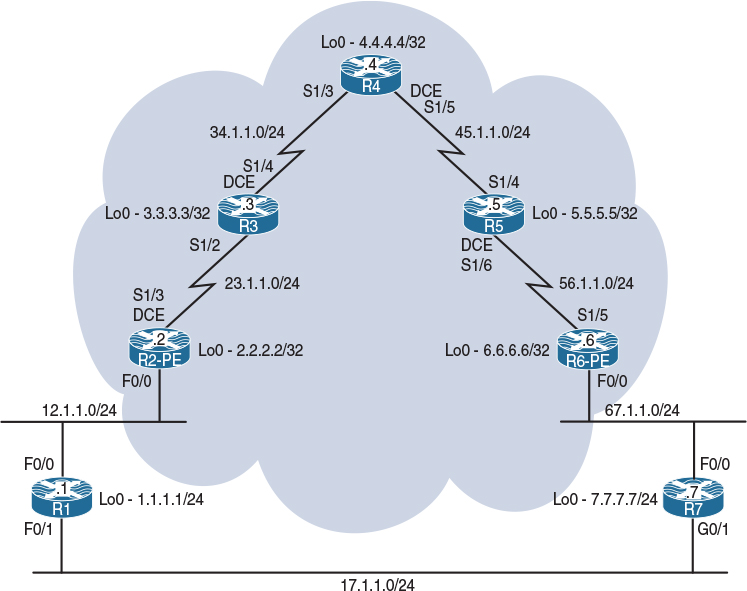
Figure 15-5 Configuring RIPv2 Routing in a VPN
Task 1
Configure the topology shown in Figure 15-5. Do not configure any routing protocol, or the F0/1 interface of R1 and the G0/1 interface of R7. Use a VLAN ID of your choice.
On SW1:
SW1(config)# interface range FastEthernet0/1-2
SW1(config-if-range)# switchport mode access
SW1(config-if-range)# switchport access vlan 12
% Access VLAN does not exist. Creating vlan 12
SW1(config-if-range)# no shutdown
SW1(config)# interface range FastEthernet0/6-7
SW1(config-if-range)# switchport mode access
SW1(config-if-range)# switchport access vlan 67
% Access VLAN does not exist. Creating vlan 67
SW1(config-if-range)# no shutdown
On R1:
R1(config)# interface loopback0
R1(config-if)# ip address 1.1.1.1 255.255.255.0
R1(config)# interface FastEthernet0/0
R1(config-if)# ip address 12.1.1.1 255.255.255.0
R1(config-if)# no shutdown
On R2:
R2(config)# interface loopback0
R2(config-if)# ip address 2.2.2.2 255.255.255.255
R2(config)# interface FastEthernet0/0
R2(config-if)# ip address 12.1.1.2 255.255.255.0
R2(config-if)# no shutdown
R2(config-if)# interface Serial1/3
R2(config-if)# clock rate 64000
R2(config-if)# ip address 23.1.1.2 255.255.255.0
R2(config-if)# no shutdown
On R3:
R3(config)# interface loopback0
R3(config-if)# ip address 3.3.3.3 255.255.255.255
R3(config)# interface Serial1/2
R3(config-if)# ip address 23.1.1.3 255.255.255.0
R3(config-if)# no shutdown
R3(config)# interface Serial1/4
R3(config-if)# clock rate 64000
R3(config-if)# ip address 34.1.1.3 255.255.255.0
R3(config-if)# no shutdown
On R4:
R4(config)# interface loopback0
R4(config-if)# ip address 4.4.4.4 255.255.255.255
R4(config)# interface Serial1/3
R4(config-if)# ip address 34.1.1.4 255.255.255.0
R4(config-if)# no shutdown
R4(config)# interface Serial1/5
R4(config-if)# clock rate 64000
R4(config-if)# ip address 45.1.1.4 255.255.255.0
R4(config-if)# no shutdown
On R5:
R5(config)# interface loopback0
R5(config-if)# ip address 5.5.5.5 255.255.255.255
R5(config)# interface Serial1/4
R5(config-if)# ip address 45.1.1.5 255.255.255.0
R5(config-if)# no shutdown
R5(config)# interface Serial1/6
R5(config-if)# clock rate 64000
R5(config-if)# ip address 56.1.1.5 255.255.255.0
R5(config-if)# no shutdown
On R6:
R6(config)# interface loopback0
R6(config-if)# ip address 6.6.6.6 255.255.255.255
R6(config)# interface Serial1/5
R6(config-if)# ip address 56.1.1.6 255.255.255.0
R6(config-if)# no shutdown
R6(config)# interface FastEthernet0/0
R6(config-if)# ip address 67.1.1.6 255.255.255.0
R6(config-if)# no shutdown
On R7:
R7(config)# interface loopback0
R7(config-if)# ip address 7.7.7.7 255.255.255.0
R7(config)# interface GigabitEthernet0/0
R7(config-if)# ip address 67.1.1.7 255.255.255.0
R7(config-if)# no shutdown
Task 2
Configure OSPF on the core MPLS routers (R2 to R6). You should run OSPF Area 0 on the Lo0 interfaces and the links that connect these routers to each other. The router IDs of R2, R3, R4, R5, and R6 should be configured as 0.0.0.2, 0.0.0.3, 0.0.0.4, 0.0.0.5, and 0.0.0.6 respectively. Do not configure OSPF between R1 and R2 and between R6 and R7.
On R2:
R2(config)# router ospf 1
R3(config-router)# router-id 0.0.0.2
R2(config-router)# network 2.2.2.2 0.0.0.0 area 0
R2(config-router)# network 23.1.1.2 0.0.0.0 area 0
On R3:
R3(config)# router ospf 1
R2(config-router)# router-id 0.0.0.3
R3(config-router)# network 3.3.3.3 0.0.0.0 area 0
R3(config-router)# network 23.1.1.3 0.0.0.0 area 0
R3(config-router)# network 34.1.1.3 0.0.0.0 area 0
You should see the following console message:
%OSPF-5-ADJCHG: Process 1, Nbr 0.0.0.2 on Serial1/2 from LOADING to FULL,
Loading Done
On R4:
R4(config)# router ospf 1
R4(config-router)# router-id 0.0.0.4
R4(config-router)# network 4.4.4.4 0.0.0.0 area 0
R4(config-router)# network 34.1.1.4 0.0.0.0 area 0
R4(config-router)# network 45.1.1.4 0.0.0.0 area 0
Now we will transition to R5 and setup OSPF there as specified in the task.
%OSPF-5-ADJCHG: Process 1, Nbr 0.0.0.3 on Serial1/3 from LOADING to FULL,
Loading Done
On R5:
R5(config)# router ospf 1
R5(config-router)# router-id 0.0.0.5
R5(config-router)# network 5.5.5.5 0.0.0.0 area 0
R5(config-router)# network 45.1.1.5 0.0.0.0 area 0
R5(config-router)# network 56.1.1.5 0.0.0.0 area 0
R6 also needs to be added to the OSPF Domain.
%OSPF-5-ADJCHG: Process 1, Nbr 0.0.0.4 on Serial1/4 from LOADING to FULL,
Loading Done
On R6:
R6(config)# router ospf 1
R6(config-router)# router-id 0.0.0.6
R6(config-router)# network 6.6.6.6 0.0.0.0 area 0
R6(config-router)# network 56.1.1.6 0.0.0.0 area 0
Once R6 is configured you should see the following console message:
%OSPF-5-ADJCHG: Process 1, Nbr 0.0.0.5 on Serial1/5 from LOADING to FULL,
Loading Done
Let’s verify the configuration:
On R2:
R2# show ip route ospf | begin Gate
Gateway of last resort is not set
3.0.0.0/32 is subnetted, 1 subnets
O 3.3.3.3 [110/782] via 23.1.1.3, 00:01:22, Serial1/3
4.0.0.0/32 is subnetted, 1 subnets
O 4.4.4.4 [110/1563] via 23.1.1.3, 00:01:11, Serial1/3
5.0.0.0/32 is subnetted, 1 subnets
O 5.5.5.5 [110/2344] via 23.1.1.3, 00:00:59, Serial1/3
6.0.0.0/32 is subnetted, 1 subnets
O 6.6.6.6 [110/3125] via 23.1.1.3, 00:00:43, Serial1/3
34.0.0.0/24 is subnetted, 1 subnets
O 34.1.1.0 [110/1562] via 23.1.1.3, 00:01:11, Serial1/3
45.0.0.0/24 is subnetted, 1 subnets
O 45.1.1.0 [110/2343] via 23.1.1.3, 00:00:59, Serial1/3
56.0.0.0/24 is subnetted, 1 subnets
O 56.1.1.0 [110/3124] via 23.1.1.3, 00:00:43, Serial1/3
On R6:
R6# show ip route ospf | begin Gate
Gateway of last resort is not set
2.0.0.0/32 is subnetted, 1 subnets
O 2.2.2.2 [110/3125] via 56.1.1.5, 00:02:43, Serial1/5
3.0.0.0/32 is subnetted, 1 subnets
O 3.3.3.3 [110/2344] via 56.1.1.5, 00:02:43, Serial1/5
4.0.0.0/32 is subnetted, 1 subnets
O 4.4.4.4 [110/1563] via 56.1.1.5, 00:02:43, Serial1/5
5.0.0.0/32 is subnetted, 1 subnets
O 5.5.5.5 [110/782] via 56.1.1.5, 00:02:43, Serial1/5
23.0.0.0/24 is subnetted, 1 subnets
O 23.1.1.0 [110/3124] via 56.1.1.5, 00:02:43, Serial1/5
34.0.0.0/24 is subnetted, 1 subnets
O 34.1.1.0 [110/2343] via 56.1.1.5, 00:02:43, Serial1/5
45.0.0.0/24 is subnetted, 1 subnets
O 45.1.1.0 [110/1562] via 56.1.1.5, 00:02:43, Serial1/5
Task 3
Configure LDP between the core routers. These routers should use their loopback0 interfaces as their LDP router ID; the core MPLS routers (R2, R3, R4, R5, and R6) should use the following label range:
R2: 200–299
R3: 300–399
R4: 400–499
R5: 500–599
R6: 600–699
On R2:
R2(config)# mpls label range 200 299
R2(config)# mpls label protocol ldp
R2(config)# mpls ldp router-id lo0 force
R2(config)# interface Serial1/3
R2(config-if)# mpls ip
On R3:
R3(config)# mpls label protocol ldp
R3(config)# mpls ldp router-id lo0
R3(config)# mpls label range 300 399
R3(config)# interface Serial1/2
R3(config-if)# mpls ip
R3(config-if)# interface Serial1/4
R3(config-if)# mpls ip
Once R3 is configured we will move to R4 and set up the MPLS parameters and enable the interfaces.
%LDP-5-NBRCHG: LDP Neighbor 2.2.2.2:0 (1) is UP
On R4:
R4(config)# mpls label protocol ldp
R4(config)# mpls ldp router-id lo0
R4(config)# mpls label range 400 499
R4(config)# interface Serial1/3
R4(config-if)# mpls ip
R4(config)# interface Serial1/5
R4(config-if)# mpls ip
You should see the following console message; once you do you can move to R5.
%LDP-5-NBRCHG: LDP Neighbor 3.3.3.3:0 (1) is UP
On R5:
R5(config)# mpls label protocol ldp
R5(config)# mpls ldp router-id lo0
R5(config)# mpls label range 500 599
R5(config)# interface Serial1/4
R5(config-if)# mpls ip
R5(config)# interface Serial1/6
R5(config-if)# mpls ip
Lastly, R6 will be configured.
%LDP-5-NBRCHG: LDP Neighbor 4.4.4.4:0 (1) is UP
On R6:
R6(config)# mpls label protocol ldp
R6(config)# mpls ldp router-id lo0
R6(config)# mpls label range 600 699
R6(config)# interface Serial1/5
R6(config-if)# mpls ip
An adjacency should form with R5 as evidenced by the console message that should appear.
%LDP-5-NBRCHG: LDP Neighbor 5.5.5.5:0 (1) is UP
Let’s look at all the interfaces configured for label switching:
On R2:
R2# show mpls interfaces
Interface IP Tunnel BGP Static Operational
Serial1/3 Yes (ldp) No No No Yes
Let’s see the neighboring LDP LSRs:
R2# show mpls ldp neighbor
Peer LDP Ident: 3.3.3.3:0; Local LDP Ident 2.2.2.2:0
TCP connection: 3.3.3.3.45826 - 2.2.2.2.646
State: Oper; Msgs sent/rcvd: 15/14; Downstream
Up time: 00:02:26
LDP discovery sources:
Serial1/3, Src IP addr: 23.1.1.3
Addresses bound to peer LDP Ident:
23.1.1.3 34.1.1.3 3.3.3.3
Note Because the LDP RID of R3 is higher than the local router, R3 will initiate the LDP session using a high port.
R2# show mpls ldp discovery all
Local LDP Identifier:
2.2.2.2:0
Discovery Sources:
Interfaces:
Serial1/3 (ldp): xmit/recv
LDP Id: 3.3.3.3:0
R2# show mpls label range
Downstream Generic label region: Min/Max label: 200/299
On R4:
R4# show mpls interfaces
Interface IP Tunnel BGP Static Operational
Serial1/3 Yes (ldp) No No No Yes
Serial1/5 Yes (ldp) No No No Yes
R4# show mpls ldp neighbor
Peer LDP Ident: 3.3.3.3:0; Local LDP Ident 4.4.4.4:0
TCP connection: 3.3.3.3.646 - 4.4.4.4.25499
State: Oper; Msgs sent/rcvd: 14/14; Downstream
Up time: 00:02:13
LDP discovery sources:
Serial1/3, Src IP addr: 34.1.1.3
Addresses bound to peer LDP Ident:
23.1.1.3 34.1.1.3 3.3.3.3
Peer LDP Ident: 5.5.5.5:0; Local LDP Ident 4.4.4.4:0
TCP connection: 5.5.5.5.34768 - 4.4.4.4.646
State: Oper; Msgs sent/rcvd: 14/14; Downstream
Up time: 00:02:02
LDP discovery sources:
Serial1/5, Src IP addr: 45.1.1.5
Addresses bound to peer LDP Ident:
45.1.1.5 56.1.1.5 5.5.5.5
R4# show mpls ldp discovery all
Local LDP Identifier:
4.4.4.4:0
Discovery Sources:
Interfaces:
Serial1/3 (ldp): xmit/recv
LDP Id: 3.3.3.3:0
Serial1/5 (ldp): xmit/recv
LDP Id: 5.5.5.5:0
R4# show mpls label range
Downstream Generic label region: Min/Max label: 400/499
On R6:
R6# show mpls interface
Interface IP Tunnel BGP Static Operational
Serial1/5 Yes (ldp) No No No Yes
R6# show mpls ldp neighbor
Peer LDP Ident: 5.5.5.5:0; Local LDP Ident 6.6.6.6:0
TCP connection: 5.5.5.5.646 - 6.6.6.6.33139
State: Oper; Msgs sent/rcvd: 14/14; Downstream
Up time: 00:01:51
LDP discovery sources:
Serial1/5, Src IP addr: 56.1.1.5
Addresses bound to peer LDP Ident:
45.1.1.5 56.1.1.5 5.5.5.5
R6# show mpls ldp neighbor | include Peer
Peer LDP Ident: 5.5.5.5:0; Local LDP Ident 6.6.6.6:0
R6# show mpls ldp discovery all
Local LDP Identifier:
6.6.6.6:0
Discovery Sources:
Interfaces:
Serial1/5 (ldp): xmit/recv
LDP Id: 5.5.5.5:0
Task 4
Configure MP-BGP AS 100 between R2 and R6 because they represent the provider edge routers in this topology. You should configure their loopback0 interface as the source for the updates. Do not allow the BGP peers to share IPv4 routing information by default. The only BGP peering should be VPNv4.
On R2:
R2(config)# router bgp 100
R2(config-router)# no bgp default ipv4-unicast
R2(config-router)# neighbor 6.6.6.6 remote-as 100
R2(config-router)# neighbor 6.6.6.6 update-source lo0
R2(config-router)# address-family vpnv4 unicast
R2(config-router-af)# neighbor 6.6.6.6 activate
On R6:
R6(config)# router bgp 100
R6(config-router)# no bgp default ipv4-unicast
R6(config-router)# neighbor 2.2.2.2 remote-as 100
R6(config-router)# neighbor 2.2.2.2 update-source lo0
R6(config-router)# address-family vpnv4 unicast
R6(config-router-af)# neighbor 2.2.2.2 activate
You should see the following console message:
%BGP-5-ADJCHANGE: neighbor 2.2.2.2 Up
Let’s verify the configuration:
On R2:
R2# show bgp vpnv4 unicast all summary | begin Neighbor
Neighbor V AS MsgRcvd MsgSent TblVer InQ OutQ Up/Down State/PfxRcd
6.6.6.6 4 100 4 4 1 0 0 00:01:29 0
As you can see, the two commands show the same output:
On R6:
R6# show ip bgp vpnv4 all summary | begin Neighbor
Neighbor V AS MsgRcvd MsgSent TblVer InQ OutQ Up/Down State/PfxRcd
2.2.2.2 4 100 7 8 1 0 0 00:04:23 0
Task 5
Configure VRFs, RDs, and RTs based on Table 15-6.
Table 15-6 Configuration Parameters for Task 5
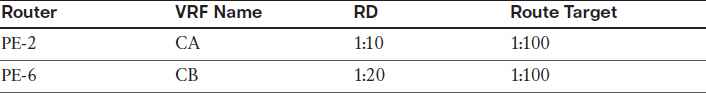
On R2:
R2(config)# vrf definition CA
R2(config-vrf)# rd 1:10
R2(config-vrf)# address-family ipv4
R2(config-vrf-af)# route-target both 1:100
On R6:
R6(config)# vrf definition CB
R6(config-vrf)# rd 1:20
R6(config-vrf)# address-family ipv4
R6(config-vrf-af)# route-target both 1:100
On R2:
R2(config)# router bgp 100
R2(config-router)# address-family vpnv4 unicast
R2(config-router-af)# neighbor 6.6.6.6 send-community extended
On R6:
R6(config)# router bgp 100
R6(config-router)# address-family vpnv4 unicast
R6(config-router-af)# neighbor 2.2.2.2 send-community extended
Let’s verify the VRF configuration:
On R2:
R2# show vrf
Name Default RD Protocols Interfaces
CA 1:10 ipv4
Let’s assign the VRF to the interfaces:
On R2:
R2(config)# interface FastEthernet0/0
R2(config-if)# vrf forwarding CA
R2(config-if)# ip address 12.1.1.2 255.255.255.0
On R6:
R6(config)# interface FastEthernet0/0
R6(config-if)# vrf forwarding CB
R6(config-if)# ip address 67.1.1.6 255.255.255.0
Let’s verify the configuration:
On R2:
R2# show vrf detail
VRF CA (VRF Id = 1); default RD 1:10; default VPNID <not set>
Interfaces:
Fa0/0
Address family ipv4 (Table ID = 1 (0x1)):
Export VPN route-target communities
RT:1:100
Import VPN route-target communities
RT:1:100
No import route-map
No export route-map
VRF label distribution protocol: not configured
VRF label allocation mode: per-prefix
Address family ipv6 not active
On R6:
R6# show ip vrf CB
Name Default RD Interfaces
CB 1:20 Fa0/0
R6# show ip vrf interfaces
Interface IP-Address VRF Protocol
Fa0/0 67.1.1.6 CB up
Let’s verify the connectivity between the PEs and CEs:
On R2:
R2# ping vrf CA 12.1.1.1
Type escape sequence to abort.
Sending 5, 100-byte ICMP Echos to 12.1.1.1, timeout is 2 seconds:
.!!!!
Success rate is 80 percent (4/5), round-trip min/avg/max = 1/1/1 ms
On R6:
R6# ping vrf CB 67.1.1.7
Type escape sequence to abort.
Sending 5, 100-byte ICMP Echos to 67.1.1.7, timeout is 2 seconds:
.!!!!
Success rate is 80 percent (4/5), round-trip min/avg/max = 1/1/4 ms
Task 6
Configure the CEs (R1 and R7) with a VRF service that incorporates OSPF as the routing protocol. R1 should use an OSPF RID of 0.0.0.1, and R7 should use an OSPF RID of 0.0.0.7. R1 and R7 should have OSPF Area 0 configured on their Lo0 and F0/0 interfaces. The loopback interfaces of R1 and R7 should be advertised with their correct mask.
Let’s start by configuring OSPF on R1 and PE-2:
On R1:
R1(config)# interface loopback0
R1(config-if)# ip ospf network point-to-point
R1(config)# router ospf 1
R1(config-router)# router-id 0.0.0.1
R1(config-router)# network 1.1.1.1 0.0.0.0 area 1
R1(config-router)# network 12.1.1.1 0.0.0.0 area 1
On PE-2:
R2(config)# router ospf 2 vrf CA
R2(config-router)# network 12.1.1.2 0.0.0.0 area 0
You should see the following console message:
%OSPF-5-ADJCHG: Process 2, Nbr 0.0.0.1 on FastEthernet0/0 from LOADING to FULL, Loading Done
Let’s verify the configuration:
On PE-2:
R2# show ip route vrf CA ospf | begin Gate
Gateway of last resort is not set
1.0.0.0/24 is subnetted, 1 subnets
O 1.1.1.0 [110/2] via 12.1.1.1, 00:01:43, FastEthernet0/0
Let’s configure OSPF on PE-6 and R7:
On R7:
R7(config)# interface loopback0
R7(config-if)# ip ospf network point-to-point
R7(config)# router ospf 1
R7(config-router)# router-id 0.0.0.7
R7(config-router)# network 7.7.7.7 0.0.0.0 area 0
R7(config-router)# network 67.1.1.7 0.0.0.0 area 0
On PE-6:
R7(config)# router ospf 2 vrf CB
R7(config-router)# network 67.1.1.6 0.0.0.0 area 0
You should see the following console message:
%OSPF-5-ADJCHG: Process 6, Nbr 0.0.0.7 on FastEthernet0/0 from LOADING to FULL,
Loading Done
Let’s verify the configuration:
On PE-6:
R6# show ip route vrf CB ospf | begin Gate
Gateway of last resort is not set
7.0.0.0/24 is subnetted, 1 subnets
O 7.7.7.0 [110/2] via 67.1.1.7, 00:01:34, FastEthernet0/0
So far you can see that the CE and PE routers are successfully exchanging routes. The next step is to perform the redistribution. You should do this in one direction first and then perform redistribution in the opposite direction. Let’s start with PE-2:
On PE-2:
R2(config)# router bgp 100
R2(config-router)# address-family ipv4 vrf CA
R2(config-router-af)# redistribute ospf 2
Let’s verify the configuration:
R2# show bgp vpnv4 unicast all | begin Network
Network Next Hop Metric LocPrf Weight Path
Route Distinguisher: 1:10 (default for vrf CA)
*> 1.1.1.0/24 12.1.1.1 2 32768 ?
*> 12.1.1.0/24 0.0.0.0 0 32768 ?
This means that PE-6 should also have these prefixes in its BGP table. Let’s verify:
On PE-6:
R6# show bgp vpnv4 unicast all | begin Network
Network Next Hop Metric LocPrf Weight Path
Route Distinguisher: 1:10
*>i1.1.1.0/24 2.2.2.2 2 100 0 ?
*>i12.1.1.0/24 2.2.2.2 0 100 0 ?
Route Distinguisher: 1:20 (default for vrf CB)
*>i1.1.1.0/24 2.2.2.2 2 100 0 ?
*>i12.1.1.0/24 2.2.2.2 0 100 0 ?
To be more specific, you can also use the following show command:
R6# show bgp vpnv4 unicast vrf CB | begin Network
Network Next Hop Metric LocPrf Weight Path
Route Distinguisher: 1:20 (default for vrf CB)
*>i1.1.1.0/24 2.2.2.2 2 100 0 ?
*>i12.1.1.0/24 2.2.2.2 0 100 0 ?
Let’s redistribute the VPNv4 routes into OSPF so that R7 can see them:
R6(config)# router ospf 2 vrf CB
R6(config-router)# redistribute bgp 100 subnets
R7 should have these routes in its routing table. Let’s verify:
On R7:
R7# show ip route ospf | begin Gate
Gateway of last resort is not set
1.0.0.0/24 is subnetted, 1 subnets
O IA 1.1.1.0 [110/3] via 67.1.1.6, 00:00:15, GigabitEthernet0/0
12.0.0.0/24 is subnetted, 1 subnets
O IA 12.1.1.0 [110/2] via 67.1.1.6, 00:00:15, GigabitEthernet0/0
R7 can see the routes advertised by R1. Let’s perform the redistribution in the opposite direction:
On PE-6:
R6(config)# router bgp 100
R6(config-router)# address-family ipv4 vrf CB
R6(config-router-af)# redistribute ospf 2
Let’s verify the configuration:
R6# show bgp vpnv4 unicast vrf CB | begin Network
Network Next Hop Metric LocPrf Weight Path
Route Distinguisher: 1:20 (default for vrf CB)
*>i1.1.1.0/24 2.2.2.2 2 100 0 ?
*> 7.7.7.0/24 67.1.1.7 2 32768 ?
*>i12.1.1.0/24 2.2.2.2 0 100 0 ?
*> 67.1.1.0/24 0.0.0.0 0 32768 ?
This means that PE-2 should have these prefixes in its BGP table:
On PE-2:
R2# show bgp vpnv4 unicast all | begin Network
Network Next Hop Metric LocPrf Weight Path
Route Distinguisher: 1:10 (default for vrf CA)
*> 1.1.1.0/24 12.1.1.1 2 32768 ?
*>i7.7.7.0/24 6.6.6.6 2 100 0 ?
*> 12.1.1.0/24 0.0.0.0 0 32768 ?
*>i67.1.1.0/24 6.6.6.6 0 100 0 ?
Route Distinguisher: 1:20
*>i7.7.7.0/24 6.6.6.6 2 100 0 ?
*>i67.1.1.0/24 6.6.6.6 0 100 0 ?
The output of the preceding show command reveals that 7.7.7.0/24 and 67.1.1.0/24 are in the BGP table of PE-2. Let’s redistribute BGP into OSPF so R1 can see the routes advertised by R7:
R2(config)# router ospf 2 vrf CA
R2(config-router)# redistribute bgp 100 subnets
Let’s verify the configuration:
On R1:
R1# show ip route ospf | begin Gate
Gateway of last resort is not set
7.0.0.0/24 is subnetted, 1 subnets
O IA 7.7.7.0 [110/3] via 12.1.1.2, 00:00:07, FastEthernet0/0
67.0.0.0/24 is subnetted, 1 subnets
O IA 67.1.1.0 [110/2] via 12.1.1.2, 00:00:07, FastEthernet0/0
Sure enough, R1 can see the routes, but once again they are showing up as E2. Let’s test this configuration:
R1# ping 7.7.7.7
Type escape sequence to abort.
Sending 5, 100-byte ICMP Echos to 7.7.7.7, timeout is 2 seconds:
!!!!!
Success rate is 100 percent (5/5), round-trip min/avg/max = 120/120/124 ms
R1# ping 7.7.7.7 source loopback0
Type escape sequence to abort.
Sending 5, 100-byte ICMP Echos to 7.7.7.7, timeout is 2 seconds:
Packet sent with a source address of 1.1.1.1
!!!!!
Success rate is 100 percent (5/5), round-trip min/avg/max = 120/121/124 ms
Task 7
Configure the F0/1 interface of R1 and the G0/1 interface of R7 in OSPF Area 0. This link should be used as a backup link to the MPLS cloud. The CE routers (R1 and R7) should see each other’s routes as intra-area. You must use sham-link to accomplish this task. Use a VLAN ID of your choice.
On SW2:
SW2(config)# interface range FastEthernet0/1,FastEthernet0/7
SW2(config-if-range)# switchport mode access
SW2(config-if-range)# switchport access vlan 17
% Access VLAN does not exist. Creating vlan 17
SW2(config-if-range)# no shutdown
On R1:
R1(config)# interface FastEthernet0/1
R1(config-if)# ip address 17.1.1.1 255.255.255.0
R1(config-if)# no shutdown
On R7:
R7(config)# interface GigabitEthernet0/1
R7(config-if)# ip address 17.1.1.7 255.255.255.0
R7(config-if)# no shutdown
Let’s verify the configuration:
R7# ping 17.1.1.1
Type escape sequence to abort.
Sending 5, 100-byte ICMP Echos to 17.1.1.1, timeout is 2 seconds:
.!!!!
Success rate is 80 percent (4/5), round-trip min/avg/max = 1/1/4 ms
Let’s run OSPF Area 0 on this link:
On R1:
R1(config)# router ospf 1
R1(config-router)# network 17.1.1.1 0.0.0.0 area 0
On R7:
R7(config)# router ospf 1
R7(config-router)# network 17.1.1.7 0.0.0.0 area 0
You should see the following console message:
%OSPF-5-ADJCHG: Process 1, Nbr 0.0.0.7 on FastEthernet0/1 from LOADING to FULL,
Loading Done
Let’s verify the configuration:
On R1:
R1# show ip route ospf | begin Gate
Gateway of last resort is not set
7.0.0.0/24 is subnetted, 1 subnets
O 7.7.7.0 [110/2] via 17.1.1.7, 00:00:25, FastEthernet0/1
67.0.0.0/24 is subnetted, 1 subnets
O 67.1.1.0 [110/2] via 17.1.1.7, 00:00:25, FastEthernet0/1
Note The routes are reachable via the backup link. Manipulating the OSPF cost will not change the routing table because intra-area routes are always preferred over inter-area routes. One way to fix this problem is to configure a sham link.
A sham link was created to resolve this problem by extending OSPF Area 0 from one customer to the other, making Area 0 contiguous. Sham link is an OSPF intra-area link configured between the two PE routers. A sham link is included in the SPF calculation, just like any other link in OSPF.
Follow these steps to configure a sham link:
1. Configure a loopback interface on R2 and another one on R6, and then assign an IP address with a prefix length of 32.
2. Enable VRF forwarding on the loopback interfaces (in this case, vrf forwarding CA on R2 and vrf forwarding CB on R6).
3. Advertise the loopback interfaces configured in step 1 in BGP. These loopback interfaces should be advertised under address-family ipv4 vrf CA on R2 and address-family ipv4 vrf CB on R6.
4. Configure the sham link under OSPF. This should be done under router ospf 2 vrf CA on R2 and router ospf 2 vrf CB on R7.
Step 1. Configure the loopback with a prefix length of 32:
On R2:
R2(config-router)# interface loopback26
R2(config-if)# ip address 26.1.1.2 255.255.255.255
On R6:
R6(config)# interface loopback62
R6(config-if)# ip address 26.1.1.6 255.255.255.255
Step 2. Configure VRF forwarding on the loopback interface:
On R2:
R2(config)# interface loopback26
R2(config-if)# vrf forwarding CA
R2(config-if)# ip addr 24.1.1.2 255.255.255.255
On R6:
R6(config)# interface loopback62
R6(config-if)# vrf forwarding CB
R6(config-if)# ip address 24.1.1.4 255.255.255.255
Step 3. Advertise the IP address of the loopback interfaces in MP-BGP:
On R2:
R2(config)# router bgp 100
R2(config-router)# address-family ipv4 vrf CA
R2(config-router-af)# network 26.1.1.2 mask 255.255.255.255
On R6:
R6(config-if)# router bgp 100
R6(config-router)# address-family ipv4 vrf CB
R6(config-router-af)# network 26.1.1.6 mask 255.255.255.255
Step 4. Configure the sham link:
On R2:
R2(config)# router ospf 2 vrf CA
R2(config-router)# area 0 Sham-link 26.1.1.2 26.1.1.6 cost 1
On R6:
R6(config)# router ospf 2 vrf CB
R6(config-router)# area 0 Sham-link 26.1.1.6 26.1.1.2 cost 1
You should see the following console message:
%OSPF-5-ADJCHG: Process 2, Nbr 12.1.1.2 on OSPF_SL0 from LOADING to FULL,
Loading Done
Let’s verify the configuration:
On R2:
R2# show ip ospf sham-links
Sham Link OSPF_SL0 to address 26.1.1.6 is up
Area 0 source address 26.1.1.2
Run as demand circuit
DoNotAge LSA allowed. Cost of using 1 State POINT_TO_POINT,
Timer intervals configured, Hello 10, Dead 40, Wait 40,
Hello due in 00:00:08
Adjacency State FULL (Hello suppressed)
Index 2/2, retransmission queue length 0, number of retransmission 0
First 0x0(0)/0x0(0) Next 0x0(0)/0x0(0)
Last retransmission scan length is 0, maximum is 0
Last retransmission scan time is 0 msec, maximum is 0 msec
Area 0 is the source for the sham link. This will commonly match the area that has been configured between the PE and the CE. This connection is considered up and operational at this time.
As you can see, this connection will run as a point-to-point demand circuit with a cost of 1. The remaining timers reflect normal OSPF peering.
On R2:
R2# show ip ospf neighbor
Neighbor ID Pri State Dead Time Address Interface
0.0.0.3 0 FULL/ - 00:00:31 23.1.1.3 Serial1/3
67.1.1.6 0 FULL/ - - 26.1.1.6 OSPF_SL0
0.0.0.1 1 FULL/DR 00:00:34 12.1.1.1 FastEthernet0/0
On R1:
R1# show ip route ospf | begin Gate
Gateway of last resort is not set
7.0.0.0/24 is subnetted, 1 subnets
O 7.7.7.0 [110/2] via 17.1.1.7, 00:32:07, FastEthernet0/1
26.0.0.0/32 is subnetted, 2 subnets
O E2 26.1.1.2 [110/1] via 12.1.1.2, 00:08:57, FastEthernet0/0
O E2 26.1.1.6 [110/1] via 12.1.1.2, 00:07:44, FastEthernet0/0
67.0.0.0/24 is subnetted, 1 subnets
O 67.1.1.0 [110/2] via 17.1.1.7, 00:32:07, FastEthernet0/1
Note The routers still prefer the backup link because of the OSPF cost. You can see that the routes are no longer inter-area routes and they have preserved their true route type.
The routers see the routes through the provider and the backup link as intra-area routes; therefore, the cost can be manipulated such that the routers will take the provider as their primary, and the backup link will be used only if the primary link is down.
Let’s see the actual cost through the provider by shutting down the backup link:
On R1:
R1(config)# interface FastEthernet0/1
R1(config-if)# shutdown
The following show command reveals the OSPF cost through the provider:
R1# show ip route ospf | begin Gate
Gateway of last resort is not set
7.0.0.0/24 is subnetted, 1 subnets
O 7.7.7.0 [110/4] via 12.1.1.2, 00:00:18, FastEthernet0/0
17.0.0.0/24 is subnetted, 1 subnets
O 17.1.1.0 [110/8] via 12.1.1.2, 00:00:18, FastEthernet0/0
26.0.0.0/32 is subnetted, 2 subnets
O E2 26.1.1.2 [110/1] via 12.1.1.2, 00:06:14, FastEthernet0/0
O E2 26.1.1.6 [110/1] via 12.1.1.2, 00:06:14, FastEthernet0/0
67.0.0.0/24 is subnetted, 1 subnets
O 67.1.1.0 [110/3] via 12.1.1.2, 00:00:18, FastEthernet0/0
In order to force the provider link to be used as the primary and the f0/1 link as the backup, a cost of 5 is assigned to the backup link:
On R1:
R1(config)# interface FastEthernet0/0
R1(config-if)# no shutdown
R1(config)# interface FastEthernet0/1
R1(config-if)# ip ospf cost 5
R1(config-if)# no shutdown
Let’s verify the configuration:
On R1:
R1# show ip route ospf | begin Gate
Gateway of last resort is not set
7.0.0.0/24 is subnetted, 1 subnets
O 7.7.7.0 [110/4] via 12.1.1.2, 00:01:12, FastEthernet0/0
26.0.0.0/32 is subnetted, 2 subnets
O E2 26.1.1.2 [110/1] via 12.1.1.2, 00:01:12, FastEthernet0/0
O E2 26.1.1.6 [110/1] via 12.1.1.2, 00:01:12, FastEthernet0/0
67.0.0.0/24 is subnetted, 1 subnets
O 67.1.1.0 [110/3] via 12.1.1.2, 00:01:12, FastEthernet0/0
On R7:
R7(config)# interface GigabitEthernet0/1
R7(config-if)# ip ospf cost 5
R7# show ip route ospf | begin Gate
Gateway of last resort is not set
1.0.0.0/24 is subnetted, 1 subnets
O 1.1.1.0 [110/4] via 67.1.1.6, 00:00:14, GigabitEthernet0/0
12.0.0.0/24 is subnetted, 1 subnets
O 12.1.1.0 [110/3] via 67.1.1.6, 00:00:14, GigabitEthernet0/0
26.0.0.0/32 is subnetted, 2 subnets
O E2 26.1.1.2 [110/1] via 67.1.1.6, 00:19:06, GigabitEthernet0/0
O E2 26.1.1.6 [110/1] via 67.1.1.6, 00:17:53, GigabitEthernet0/0
Erase the startup configuration of the routers and reload them before proceeding to the next lab.
Lab 15-6: BGP Routing in a VPN
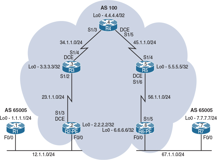
Figure 15-6 Configuring RIPv2 Routing in a VPN
Figure 15-6 illustrates the topology that will be used in the following tasks.
Task 1 through Task 5 of Lab 15-2 are identical to the first five tasks in this lab. Therefore, repeat Tasks 1 through 5 before proceeding to the next task.
Task 6
Configure BGP as the MPLS routing context between the CEs (R1 and R7) and their respective PEs (R2 and R6). The customer AS of 65005 should be assigned to both customer sites, whereas the provider should use AS 100.
Let’s configure the CE routers:
On R1:
R1(config)# router bgp 65005
R1(config-router)# no auto-summary
R1(config-router)# neighbor 12.1.1.2 remote 100
R1(config-router)# network 1.1.1.0 mask 255.255.255.0
On R7:
R7(config)# router bgp 65005
R7(config-router)# no auto-summary
R7(config-router)# neighbor 67.1.1.6 remote 100
R7(config-router)# network 7.7.7.0 mask 255.255.255.0
Let’s configure the PE routers to establish a peer session with the CE routers:
Note No redistribution is necessary for MP-BGP. The peering is identical to that of normal BGP, except it is in the VPN instead. However, normal BGP rules apply within the VPN.
On R2:
R2(config)# router bgp 100
R2(config-router)# address-family ipv4 vrf CA
R2(config-router-af)# neighbor 12.1.1.1 remote 65005
You should see the following console messages before moving on:
%BGP-5-ADJCHANGE: neighbor 12.1.1.1 vpn vrf CA Up
Let’s verify the configuration:
R2# show bgp vpnv4 unicast vrf CA | begin Network
Network Next Hop Metric LocPrf Weight Path
Route Distinguisher: 1:10 (default for vrf CA)
*> 1.1.1.0/24 12.1.1.1 0 0 65005 i
On R6:
R6(config)# router bgp 100
R6(config-router)# address-family ipv4 vrf CB
R6(config-router-af)# neighbor 67.1.1.7 remote 65005
You should see the following console messages before moving on:
%BGP-5-ADJCHANGE: neighbor 67.1.1.7 vpn vrf CB Up
Let’s verify the configuration:
On R6:
R6# show bgp vpnv4 unicast vrf CB | begin Network
Network Next Hop Metric LocPrf Weight Path
Route Distinguisher: 1:20 (default for vrf CB)
*>i1.1.1.0/24 2.2.2.2 0 100 0 65005 i
*> 7.7.7.0/24 67.1.1.7 0 0 65005 i
It is not enough to verify the configuration on R6; we also need to verify on both R1 and R7.
On R1:
R1# show ip bgp | begin Net
Network Next Hop Metric LocPrf Weight Path
*> 1.1.1.0/24 0.0.0.0 0 32768 i
On R7:
R7# show ip bgp | begin Network
Network Next Hop Metric LocPrf Weight Path
*> 7.7.7.0/24 0.0.0.0 0 32768 i
Although the routes were verified to have been received via MP-BGP and redistribution is not a problem that can exist here, the routes are not learned by the CE routers. This is a result of the normal BGP process of loop prevention; the AS numbers of both customers match. There are two ways to resolve this matter:
1. Configuring the CE solution using allowas-in.
2. Configuring the PE solution using as-override.
Let’s configure the CE solution and verify:
On R1:
R1(config)# router bgp 65005
R1(config-router)# neighbor 12.1.1.2 allowas-in
This feature can be used as an alternative if the service provider controls the CE router(s).
When network 7.7.7.0/24 is advertised by R7, the AS number is prepended (65005), which is used as a loop-prevention mechanism in BGP. The prefix is received by the provider and then advertised to R1, which is also in AS 65005 (same as R7’s AS). When R1 receives the route, it sees its own AS number in the AS-Path attribute and it discards the route as a loop-avoidance mechanism. The allowas-in command allows the local router to receive routes even if the local router sees its own AS in the AS-Path attribute.
Let’s verify the configuration:
On R1:
R1# show ip bgp | begin Network
Network Next Hop Metric LocPrf Weight Path
*> 1.1.1.0/24 0.0.0.0 0 32768 i
*> 7.7.7.0/24 12.1.1.2 0 100 65005 i
The same feature must be configured on R7:
On R7:
R7(config)# router bgp 65005
R7(config-router)# neighbor 67.1.1.6 allowas-in
Let’s verify the configuration:
On R7:
R7# show ip bgp | begin Network
Network Next Hop Metric LocPrf Weight Path
*> 1.1.1.0/24 67.1.1.6 0 100 65005 i
*> 7.7.7.0/24 0.0.0.0 0 32768 i
Let’s test the configuration:
R7# ping 1.1.1.1
Type escape sequence to abort.
Sending 5, 100-byte ICMP Echos to 1.1.1.1, timeout is 2 seconds:
.....
Success rate is 0 percent (0/5)
As you can see, the ping failed—but why?
The ping was sourced from the f0/0 interface of R7, and because the IP address of this interface is not advertised to R1, the return traffic fails.
To test this condition, debug ip icmp is enabled on R1 and a ping is generated by R7 with a repeat count of 2:
On R1:
R1# debug ip icmp
ICMP packet debugging is on
On R7:
R7# ping 1.1.1.1 repeat 2
Type escape sequence to abort.
Sending 2, 100-byte ICMP Echos to 1.1.1.1, timeout is 2 seconds:
..
Success rate is 0 percent (0/2)
Let’s verify the console messages on R1:
On R1:
ICMP: echo reply sent, src 1.1.1.1, dst 67.1.1.7, topology BASE, dscp 0 topoid 0
ICMP: echo reply sent, src 1.1.1.1, dst 67.1.1.7, topology BASE, dscp 0 topoid 0
This proves that R1 is receiving the ICMP-Echo messages, but it does not have a route back to 67.1.1.7 (R7’s f0/0 interface’s IP address). Let’s fix this problem:
On R2:
R2(config)# router bgp 100
R2(config-router)# address-family ipv4 vrf CA
R2(config-router-af)# redistribute connected
On R7:
R6(config)# router bgp 100
R6(config-router)# address-family ipv4 vrf CB
R6(config-router-af)# redistribute connected
Let’s verify the configuration:
On R7:
R7# ping 1.1.1.1
Type escape sequence to abort.
Sending 5, 100-byte ICMP Echos to 1.1.1.1, timeout is 2 seconds:
!!!!!
Success rate is 100 percent (5/5), round-trip min/avg/max = 120/122/124 ms
Now let’s configure the PE routers to resolve the problem. Before the PE solution is used, let’s remove the neighbor allowas-in command from the CE routers:
On R1:
R1(config)# router bgp 65005
R1(config-router)# no neighbor 12.1.1.2 allowas-in
On R7:
R7(config)# router bgp 65005
R7(config-router)# no neighbor 67.1.1.6 allowas-in
Let’s configure the PE solution:
On R2:
R2(config)# router bgp 100
R2(config-router)# address-family ipv4 vrf CA
R2(config-router-af)# neighbor 12.1.1.1 as-override
On PE-6:
R6(config)# router bgp 100
R6(config-router)# address-family ipv4 vrf CB
R6(config-router-af)# neighbor 67.1.1.7 as-override
Let’s verify the configuration:
On R1:
R1# show ip bgp | begin Network
Network Next Hop Metric LocPrf Weight Path
*> 1.1.1.0/24 0.0.0.0 0 32768 i
*> 7.7.7.0/24 12.1.1.2 0 100 100 i
r> 12.1.1.0/24 12.1.1.2 0 0 100 ?
*> 67.1.1.0/24 12.1.1.2 0 100 ?
Note The AS number of the provider is prepended.
On R7:
R5# show ip bgp | begin Network
Network Next Hop Metric LocPrf Weight Path
*> 1.1.1.0/24 67.1.1.6 0 100 100 i
*> 7.7.7.0/24 0.0.0.0 0 32768 i
*> 12.1.1.0/24 67.1.1.6 0 100 ?
r> 67.1.1.0/24 67.1.1.6 0 0 100 ?
Unlike with the previous solution, where the AS number was ignored, using this feature the provider replaces the customer’s AS number with its own. The customers must allow prepended AS numbers; otherwise, they will not receive the BGP routes, because from the customers’ perspective, it looks like the provider has prepended its own AS number an additional time.
Erase the startup configuration of the routers and reload them before proceeding to the next lab.