Chapter 15. OSPFv2 and OSPFv3
This chapter provides information about the following topics:
![]() Using wildcard masks with OSPF areas
Using wildcard masks with OSPF areas
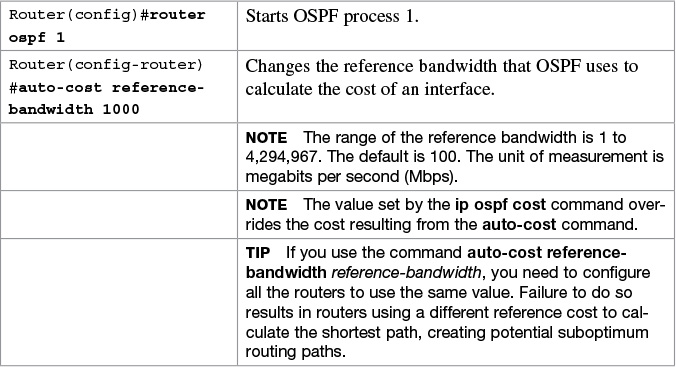
![]() OSPF auto-cost reference-bandwidth
OSPF auto-cost reference-bandwidth
![]() Enabling OSPF for IPv6 on an interface
Enabling OSPF for IPv6 on an interface
![]() Interarea OSPFv3 Route Summarization
Interarea OSPFv3 Route Summarization
![]() Enabling an IPv4 Router ID for OSPFv3
Enabling an IPv4 Router ID for OSPFv3
![]() Verifying OSPFv2 and OSPFv3 configurations
Verifying OSPFv2 and OSPFv3 configurations
![]() Troubleshooting OSPFv2 and OSPFv3
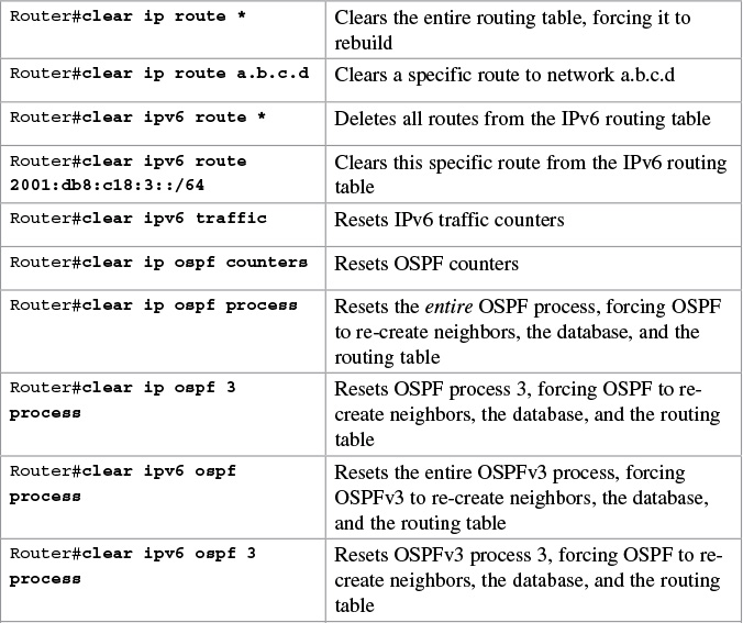
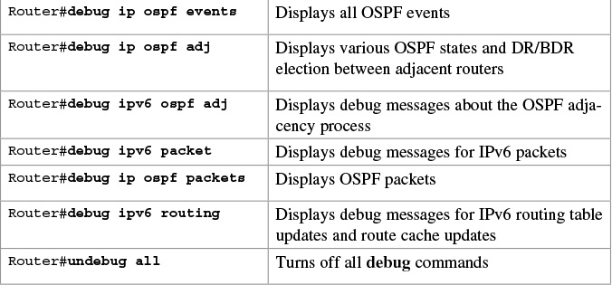
Troubleshooting OSPFv2 and OSPFv3
![]() Configuration example: single-area OSPF
Configuration example: single-area OSPF
![]() Configuration example: multiarea OSPF
Configuration example: multiarea OSPF
![]() Configuration example: IPv6 and OSPFv3
Configuration example: IPv6 and OSPFv3
OSPFv2 Versus OSPFv3
The current version of Open Shortest Path First (OSPF), OSPFv2, was developed back in the late 1980s, when some parts of OSPF were designed to compensate for the inefficiencies of routers at that time. Now that router technology has dramatically improved, and with the arrival of IPv6, rather than modify OSPFv2 for IPv6, it was decided to create a new version of OSPF (OSPFv3), not just for IPv6, but for other newer technologies, too.
In most Cisco documentation, if you see something refer to OSPF, it is assumed to be referring to OSPFv2, and working with the IPv4 protocol stack.
The earliest release of the OSPFv3 protocol worked with IPv6 exclusiviely; if you needed to run both OSPF for IPv4 and IPv6, you had to have OSPFv2 and OSPFv3 running concurrently. Newer updates to OSPFv3 are allowing for OSPFv3 to handle both IPv4 and IPv6 addressing. The combining of IPv4 and IPv6 into OSPFv3 is not part of the CCNA vendor exam objectives; it is part of the CCNP ROUTE vendor exam objectives and therefore out of scope for this guide. This guide works with the understanding that anything related to IPv4 will be using OSPFv2, and anything related to IPv6 will be using OSPFv3.
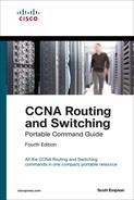
Configuring OSPF
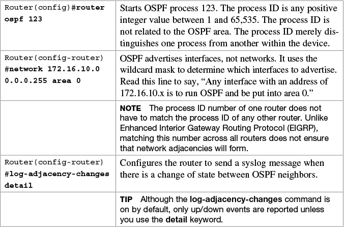
Using Wildcard Masks with OSPF Areas
When compared to an IP address, a wildcard mask identifies what addresses are matched to run OSPF and to be placed into an area:
![]() A 0 (zero) in a wildcard mask means to check the corresponding bit in the address for an exact match.
A 0 (zero) in a wildcard mask means to check the corresponding bit in the address for an exact match.
![]() A 1 (one) in a wildcard mask means to ignore the corresponding bit in the address—can be either 1 or 0.
A 1 (one) in a wildcard mask means to ignore the corresponding bit in the address—can be either 1 or 0.
Example 1: 172.16.0.0 0.0.255.255
172.16.0.0 = 10101100.00010000.00000000.00000000
0.0.255.255 = 00000000.00000000.11111111.11111111
Result = 10101100.00010000.xxxxxxxx.xxxxxxxx
172.16.x.x (Anything between 172.16.0.0 and 172.16.255.255 matches the example statement.)
Tip
An octet in the wildcard mask of all 0s means that the octet has to match the address exactly. An octet in the wildcard mask of all 1s means that the octet can be ignored.
Example 2: 172.16.8.0 0.0.7.255
172.168.8.0 = 10101100.00010000.00001000.00000000
0.0.0.7.255 = 00000000.00000000.00000111.11111111
result = 10101100.00010000.00001xxx.xxxxxxxx
00001xxx = 00001000 to 00001111 = 8–15
xxxxxxxx = 00000000 to 11111111 = 0–255
Anything between 172.16.8.0 and 172.16.15.255 matches the example statement.
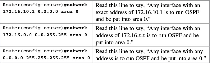
Configuring Multiarea OSPF

Running two different OSPF processes does not create multiarea OSPF; it merely creates two separate instances of OSPF that do not communicate with each other. To create multiarea OSPF, you use two separate network statements and advertise two different links into different areas.
Note
You can enable OSPF directly on an interface with the ip ospf process ID area area number command. Because this command is configured directly on the interface, it takes precedence over the network area command entered in router configuration mode.
Tip
If you have problems determining which wildcard mask to use to place your interfaces into an OSPF area, use the ip ospf process ID area area number command directly on the interface.
Tip
If you assign interfaces to OSPF areas without first using the router ospf x command, the router creates the router process for you, and it shows up in a show running-config output.
Multiarea OSPF Router Types
There are different types of definitions of routers when working with multiarea OSPF:
![]() Internal—Internal routers have all their interfaces within the same OSPF area.
Internal—Internal routers have all their interfaces within the same OSPF area.
![]() Backbone router—A router in which at least one of its interfaces is part of the backbone area (Area 0).
Backbone router—A router in which at least one of its interfaces is part of the backbone area (Area 0).
![]() Area Border Router (ABR)—An ABR is a router that has at least two interfaces in two different areas. Typically this is designed to be one interface in the backbone area (Area 0) and at least one interface in a different area. It establishes a connection between the backbone area and other areas.
Area Border Router (ABR)—An ABR is a router that has at least two interfaces in two different areas. Typically this is designed to be one interface in the backbone area (Area 0) and at least one interface in a different area. It establishes a connection between the backbone area and other areas.
![]() Autonomous System Boundary Router (ASBR)—An ASBR is a router that has at least one interface in one OSPF area and at least one interface in a different routing process (either another dynamic routing protocol or a static route to a remote destination that is being redistributed into OSPF).
Autonomous System Boundary Router (ASBR)—An ASBR is a router that has at least one interface in one OSPF area and at least one interface in a different routing process (either another dynamic routing protocol or a static route to a remote destination that is being redistributed into OSPF).
It is possible to have a combination of these terms used to describe a router. For example, a router with all of its interfaces belonging to Area 0 could be considered an Internal Backbone router.
These definitions will be used in the Configuration Example: Multiarea OSPF in this chapter to identify the router types.
Loopback Interfaces

Router ID

Note
To choose the router ID at the time of OSPF process initialization, the router uses the following criteria in this specific order:
1. Use the router ID specified in the router-id w.x.y.z command.
2. Use the highest IP address of all active loopback interfaces on the router.
3. Use the highest IP address among all active nonloopback interfaces.
Note
To have the manually configured router ID take effect, you must clear the OSPF routing process with the clear ip ospf process command.
Note
There is no IPv6 form of router ID. All router IDs are 32-bit numbers in the form of an IPv4 address. Even if a router is running IPv6 exclusiviely, the router ID is still in the form of an IPv4 address.

Passive Interfaces

Modifying Cost Metrics

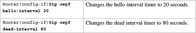
Timers
Caution
Hello and dead interval timers must match between two routers for those routers to become neighbors.
Note
The default hello timer is 10 seconds on multiaccess and point-to-point segments. The default hello timer is 30 seconds on nonbroadcast multiaccess (NBMA) segments such as Frame Relay, X.25, and ATM.
Note
The default dead interval timer is 40 seconds on multiaccess and point-to-point segments. The default dead timer is 120 seconds on NBMA segments such as Frame Relay, X.25, and ATM.
Note
If you change the hello interval timer, the dead interval timer is automatically adjusted to four times the new hello interval timer.
Propagating a Default Route

Note
Route summarization is not part of the CCNA vendor exam objectives.
In OSPF, there are two different types of summarization:
![]() Interarea route summarization
Interarea route summarization
![]() External route summarization
External route summarization
The sections that follow provide the commands necessary to configure both types of summarization.
Interarea Route Summarization

External Route Summarization

IPv6 and OSPFv3
This section covers using IPv6 with OSPFv3. For the purposes of the CCNA vendor exam objectives, OSPFv3 only deals with IPv6 addresses.
Note
For an excellent overview of IPv6, I strongly recommend you read Rick Graziani’s book from Cisco Press: IPv6 Fundamentals: A Straightforward Approach to Understanding IPv6.
Enabling OSPF for IPv6 on an Interface

Interarea OSPFv3 Route Summarization


Verifying OSPFv2 and OSPFv3 Configurations


Configuration Example: Single-Area OSPF
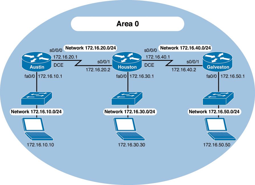
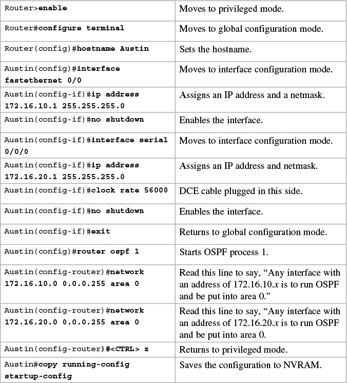
Figure 15-1 shows the network topology for the configuration that follows, which demonstrates how to configure single-area OSPF using the commands covered in this chapter.
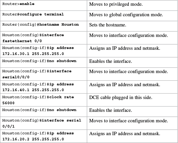
Houston Router


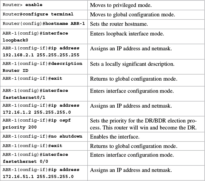
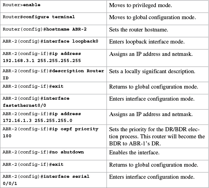
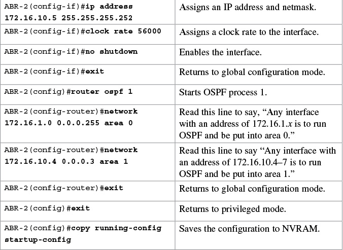
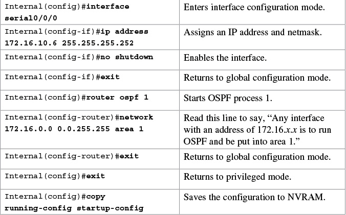
Configuration Example: Multiarea OSPF
Figure 15-2 shows the network topology for the configuration that follows, which demonstrates how to configure multiarea OSPF using the commands covered in this chapter.

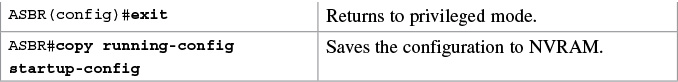
ASBR Router


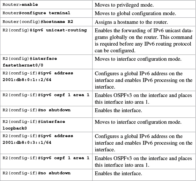
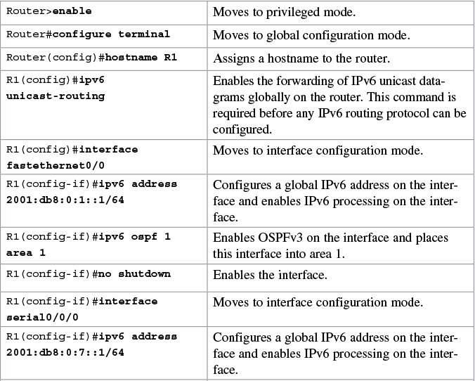
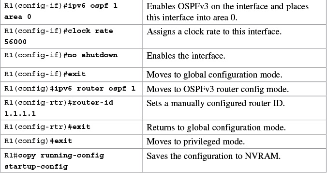
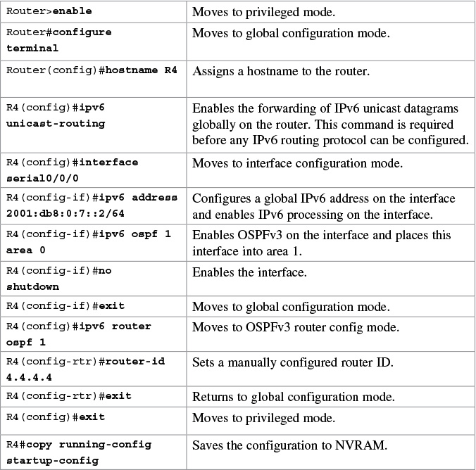
Configuration Example: IPv6 and OSPFv3
Figure 15-3 shows the network topology for the configuration that follows, which demonstrates how to configure IPv6 and OSPFv3 using the commands covered in this chapter.
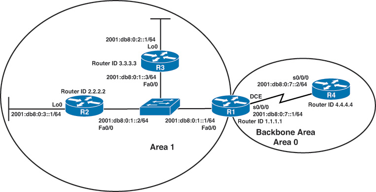
R3 Router