
Chapter 1
Wireless Design Requirements
This chapter covers the following topics:
Following a Design Process: This section describes the framework of a formal design process that Cisco recommends for the lifecycle of a network.
Evaluating Customer Requirements: This section gives an overview of common parameters you should investigate with the end customer prior to beginning a wireless network design and site survey.
Evaluating Client Requirements: This section discusses wireless device specifications and how you can interpret them as guidelines for a wireless design.
Choosing AP Types: This brief section describes the basic AP types and how you can apply them to a wireless design.
Evaluating Security Requirements: This section covers some design considerations related to security requirements in a wireless network.
AP Deployment Models: This section describes the basic guidelines for deploying APs in network designs that focus on generic data, real-time applications, and location-based services.
This chapter covers the following ENWLSD exam topics:
1.1 Collect design requirements and evaluate constraints
1.1.a Client density
1.1.b Real-time applications
1.1.c AP type
1.1.d Deployment type (data, location, voice, video)
1.1.e Security
Have you ever gone to a new location—perhaps an airport, hotel, restaurant, hospital, or even someone’s home—and hoped you could use a wireless network with a device you were carrying? Think about the process you went through. First, you had to find a wireless network in that location, attempt to join it, and then attempt to use it. Hopefully you were successful and the network performed adequately during the time you used it. What applications did you use at the time? How many other people were using the same network along with you? Most likely you were a guest on the network, so you may have suffered through a less-than-enjoyable experience. Now suppose you were using a medical device that controlled a life support or patient safety function. Would your expectations change? You would probably want the wireless network to be very fast, very reliable, and very available in every possible location.
Wireless networks might appear to be simple and ubiquitous to the casual user, but they can be quite complex behind the scenes. In order to properly support all wireless users, a wireless network must be properly designed and implemented. In this chapter, you learn more about formal network design processes, as well as what important information you should gather from customers regarding their wireless network. You also learn how to evaluate several types of requirements and constraints that will help guide you toward an effective wireless design.
“Do I Know This Already?” Quiz
The “Do I Know This Already?” quiz allows you to assess whether you should read this entire chapter thoroughly or jump to the “Exam Preparation Tasks” section. If you are in doubt about your answers to these questions or your own assessment of your knowledge of the topics, read the entire chapter. Table 1-1 lists the major headings in this chapter and their corresponding “Do I Know This Already?” quiz questions. You can find the answers in Appendix D, “Answers to the ‘Do I Know This Already?’ Quizzes and Review Questions.”
Table 1-1 “Do I Know This Already?” Section-to-Question Mapping
Foundation Topics Section |
Questions |
|---|---|
Following a Design Process |
1 |
Evaluating Customer Requirements |
2 |
Evaluating Client Requirements |
3–5 |
Choosing AP Types |
6 |
Evaluating Security Requirements |
7 |
AP Deployment Models |
8–10 |
1. Which one of the following describes a formal design process often used in the lifecycle of a network?
FRA
IEEE
PPDIOO
PBR
2. When you meet with a customer to gather information about an upcoming wireless project, which one of the following things will be most helpful as you prepare to perform a site survey?
The scope of the project
A list of buildings and locations that need wireless service
Floor plans of buildings that need wireless service
Diagrams of the wired network infrastructure
3. Suppose you collect information about the wireless devices that will be used at a customer’s site. Which one of the following specifications will determine which bands you should enable in your wireless design?
802.11b/g/n
Data rates: 6–54Mbps
Antenna gain: 2.0 dBi
Sensitivity: −90 dBm
4. Which one of the following wireless client specifications is helpful in designing the size of an AP cell?
The antenna gain
The receiver sensitivity
The number of spatial streams
The data rates supported
5. A high-density area in a wireless design is determined by which one of the following things?
More clients are using the 5GHz band than the 2.4GHz band.
A small number of clients in an area are using high-bandwidth applications.
A higher number of clients associate with each AP in an area.
A higher amount of RF coverage is needed in an area.
6. Which one of the following applications would be the most appropriate use for an AP model that has internal antennas?
A location where a relatively wide coverage area is desired
A location where coverage is needed toward one side of the AP
A location where a patch antenna’s pattern is required
A location where an omnidirectional antenna is not desirable
7. Suppose a customer wants potential users to enter a username and password before being granted access to the wireless network. Which of the following items could you add to the list of requirements for your wireless design to meet the customer’s requirement?
RADIUS servers
AAA servers
ISE servers
AES servers
8. In a data deployment model, which one of the following statements is true?
Strict jitter requirements must be met.
Strict latency requirements must be met.
Strict packet loss requirements must be met.
No specific requirements must be met.
9. Suppose a customer wants to use an application that requires jitter to be less than 30 milliseconds. Which one of the following AP deployment models is indicated for the wireless network design?
Data deployment model
Voice deployment model
Location deployment model
There is not enough information given to determine a deployment model.
10. Which one of the following parameters is used to estimate a client device’s location in a wireless network?
Wireless MAC address
Ping response times
Phase differential
Received signal strength
Foundation Topics
Following a Design Process
Like any other complex network, a wireless network design should be approached by following a formal design process. Even if you have built a simple wireless network at home with one access point, you have likely gone through several different steps in a design process. For example, you probably began by determining that your home needed a wireless network, and then you set aside money to buy the AP and picked a date to do the work. You probably decided to install the AP in a central location to give RF coverage over the most living space. You might have thought about which 802.11 features you would like to use. Next, you installed and configured the AP, and then you and your family enjoyed using the new wireless network. Finally, perhaps a neighbor began using the same channel as your AP, so you had to move yours to a different channel to improve its performance.
The process just described follows a well-known Cisco lifecycle process that applies to both simple and very large, complex networks alike. The PPDIOO process is named from the first letter of its six phases: Prepare, Plan, Design, Implement, Operate, Optimize. As the left portion of Figure 1-1 illustrates, PPDIOO begins with the Prepare phase, where an organization usually determines a business case and a high-level design for a new network. As an example, suppose a new wing will be added to an existing building, and the new wing will need a wireless network to support the business’s users and devices. This requirement leads into the Plan phase, which involves examining details about the site, determining any existing network to be upgraded or migrated, and identifying a set of network requirements. The Plan phase leads into the Design phase, where a detailed network design specification is developed. The detailed design usually specifies the equipment and features needed to provide the appropriate level of availability, reliability, scalability, performance, and security to support the business operations.
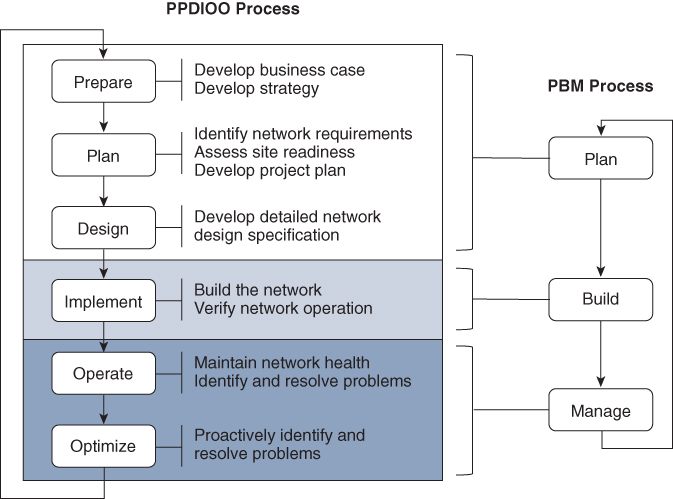
Figure 1-1 The PPDIOO and PBM Lifecycle Processes
Once a detailed design is produced, the Implement phase can begin, and the network can be built according to the design specifications. This is followed by the Operate phase, where the network implementation is put into production and maintained and monitored on a day-to-day basis. Any faults or problems should be detected and remediated too. Finally, the Optimize phase is used to replace reactive problem resolution with a more proactive approach to minimize future issues and outages. Notice that the Optimize phase also leads back into the Prepare phase so that recurring problems or other shortcomings, as well as network upgrades, can be addressed as continuous improvements. In other words, the sequence of six phases becomes an organized cycle of activities.
Cisco also uses the Plan-Build-Manage (PBM) process, illustrated in the right portion of Figure 1-1. The concept is identical to that of PPDIOO, but the process is simplified into three phases instead of six.
As you work through the chapters of this book, you will learn how to leverage your wireless expertise and knowledge as you participate in various wireless design activities. For example, you might meet with a customer to gather requirements as part of the Prepare phase. You could perform site surveys as part of the Plan and Design phases. In fact, Chapters 1–9 are devoted to Design phase–oriented work, whereas Chapters 10–15 focus on the Implement phase. Chapters 16 and 17 involve tasks like verifying, optimizing, monitoring, troubleshooting, and hardening—tasks that usually take place in the Operate and Optimize phases.
Evaluating Customer Requirements
The first step toward building a wireless network is to figure out exactly what you are trying to build. In other words, you need to develop a plan that is based on some requirements. While it is possible to build a wireless network at home by simply standing up one wireless AP with its default configuration, that approach will likely not be useful in a corporate environment. After all, you should position the AP in a location where wireless coverage is needed and where it can serve the most users. In most cases, you will need many APs, even thousands of them, to cover every area where the customer expects its wireless users to be.
The plan quickly gets more complicated when you consider all of the variables involved with one customer, which might be completely different from the variables found with another customer. For instance, physical facilities are not the same everywhere. Buildings are usually unique in shape, size, and layout. They might be constructed from different materials, which affect wireless signals in different ways. Each business might use different wireless devices, different applications, and different functions, which could require appropriate adjustments to the wireless network design and configuration.
The best approach is to begin by meeting with and interviewing the customer. Gather information about the scope of the wireless project. Is the goal to build a new network or upgrade or expand an existing one? Find out if the project should address any existing wireless problems or support increasing numbers of users.
You should identify which locations, campuses, buildings, rooms, and areas where the customer wants to offer wireless service. This information will allow you to estimate the number of wireless LAN controllers, APs, and other devices needed to provide wireless coverage. It will also let you estimate the total floor area so that you know how long it will take to walk every area to perform site survey work. You will use site surveys to determine where each AP should be located and to verify the resulting coverage once the APs become operational. You can learn more about site surveys in Chapter 2, “Conducting an Offsite Site Survey,” and Chapter 3, “Conducting an Onsite Site Survey,” in this book.
Learning more about the project scope will also reveal information about the underlying wired network infrastructure. After all, you will need to connect wireless controllers and APs to a wired data network. If the customer has multiple sites or buildings, you may need to add some connecting infrastructure to your design. You can learn more about the wired network needed to support wireless service in Chapter 4, “Physical and Logical Infrastructure Requirements.”
Find out more about the customer’s user community and note types of users and their general job functions. Which areas do they frequent? What wireless devices do they use? Which applications are critical to the users’ functions? The answers to these general questions will lead into more detailed information gathering, explained in the next sections.
Be sure to ask the customer to provide drawings of each building and floor area where wireless coverage will be needed. Electronic versions of the drawings will be invaluable as you perform site surveys. Printed versions will be useful when you mark AP locations, need to measure distances, check building materials, and jot down noteworthy things to remember about the sites.
If possible, tour the facilities so you can see every area that will need wireless coverage. Take notes and photos of typical areas to be covered. Note any special requirements and aesthetic constraints. For example, some large classrooms or auditoriums may need coverage, but APs might need to be located on high ceilings or in unexpected locations. Sometimes the customer might not want APs or antennas to be seen at all in buildings with historic or special significance. Warehouses might require unique AP locations due to shelving and stored materials. Lobbies and open walkways might need coverage if users travel through those areas and need wireless service. Keep in mind that every building and floor is unique and could require unique approaches to wireless coverage.
As you inspect the facilities and plans, make sure you understand the customer’s expectations for each area too. For example, you might notice that one building has several large classrooms and a large lobby area. If you toured the building at a time when those areas were empty, you might not realize that the customer expects every classroom to support streaming video over the wireless network and that the lobby must support large numbers of people as they move between classes. Likewise, a healthcare customer might show you a large emergency department and an outdoor area where ambulances arrive. Unless you ask, you might not realize that the customer expects the outdoor area to have full wireless coverage for emergency staff, each carrying a wireless phone, as they move in and around a large number of ambulance vehicles. Ask about the need to cover stairwells, elevators, outside entrances, and other gathering places.
Vehicles are one example of large objects that can change location over time. You might also encounter helicopters on a rooftop helipad, forklifts in a warehouse or manufacturing facility, movable shelves full of books in a library, large doors, stacks of inventory, and so on. All of these things are objects that can attenuate or block wireless signals. Even if you know about them ahead of time and can plan the wireless coverage accordingly, they might move later on and affect another location that you did not anticipate.
You should become aware of the type of wireless coverage that the customer expects in each area. Some areas might need basic wireless coverage for users who are located throughout, while other areas receive multitudes of users who are densely packed and expect a high level of network performance. In other words, always evaluate each area according to RF coverage versus capacity. These topics are covered in greater detail in Chapter 5, “Applying Wireless Design Requirements.”
Evaluating Client Requirements
It might seem obvious that the focus of a wireless design is to provide wireless coverage in all desired areas. The coverage should take the client or user population into account so that network performance is acceptable to all users, even the ones in densely populated areas. With these criteria, along with thorough site survey work, you should be able to choose the number and location of APs that are necessary.
Notice that the coverage is based on the number of “clients,” as if all wireless clients are identical in feature sets and functions. This is usually not the case. A typical corporate site can have many different types and models of wireless client devices. For example, users might have a range of laptops and tablets made by various manufacturers. They might also carry wireless phones. You might also find wireless cameras, industrial control devices, medical devices, security devices, and so on. To participate in the wireless network, all devices must be compatible with the IEEE 802.11 standard. However, each device type and model can have very different capabilities and specifications. For this reason, an effective wireless design must also address client device requirements.
The IEEE 802.11 standard is very complex and consists of several thousand pages. Every wireless device must adhere to fundamental definitions like the 802.11 frame format, clear channel assessment, and so on, but may not support every possible feature defined in the standard. For example, some client devices may support 802.11a and 802.11n but not 802.11ac. Generally, an AP can support a wide range of 802.11 features because it acts as the hub for a mixed bag of clients. Not every feature is enabled or configured on an AP, but you may have to include and tune them as part of your wireless design. As you enable, disable, or tune each feature, you should make sure that doing so does not isolate or exclude any client devices the customer wants to support.
When you meet with a customer to begin a wireless design, you should gather information about all of the wireless devices used in each facility. Find out the device type (laptop, phone, RFID tag, and so on), manufacturer, and model number and then collect a list of technical specifications. The specifications, which can often be found on a product data sheet, list things like 802.11 support, RF capabilities, supported security suites, quality of service requirements, and so on. The information you collect will serve a twofold purpose:
You can verify that your wireless design and configuration will support each device type in use
You can identify the least capable of the supported devices, which will define some minimum design requirements
As an example, suppose you have consulted a customer and learned of four types of wireless devices being used in the enterprise. The customer is a healthcare provider using mobile surveillance cameras, voice communicators, wireless phones, and embedded wireless modules, among many other devices. (The embedded module is typically found in things like hospital beds and factory equipment.) In this scenario, all four devices are critical to the organization’s mission, so your wireless design must support them completely. Other common devices, such as laptops and tablets are in use too, but their specifications are not shown for simplicity. Tables 1-2 through 1-4 list many of the device specifications you have collected.
Examining Client 802.11 Capabilities
Table 1-2 lists many of the specifications related to 802.11 functions. For example, notice that all four device types support both the 2.4 and 5GHz bands. If a device supported only one band, you would have to make sure that your design offered that band for use. As it stands, you should be able to design with dual-band APs to accommodate any device type.
Next, you might compare the values shown in the “802.11” row to see which 802.11 amendments each device type supports. Two of the devices support a/b/g/n, while the other two add support for ac. This information becomes important if you decide to disable specific data rates to improve performance and adjust the cell size of the APs. Fortunately, none of the devices requires only 802.11b, so you might think about disabling the slowest corresponding data rates. The information listed in the “Data Rates” row can also guide your rate tuning efforts.
Table 1-2 Example Wireless Device 802.11 Specifications
|
Mobile Surveillance Camera |
Voice Communicator |
Wireless Phone |
Embedded Wireless Module |
|---|---|---|---|---|
Bands Supported |
2.4GHz, 5GHz |
2.4GHz, 5GHz |
2.4GHz, 5GHz |
2.4GHz, 5GHz |
802.11 |
a/b/g/n/ac |
a/b/g/n |
a/b/g/n/ac |
a/b/g/n |
Channels 2.4GHz 5GHz |
1 to 13 36–48, 52–64, 100–140, 144, 149–161 |
11 channels 20 channels |
1 to 13 36–48, 52–64, 100–140, 149–165 |
1 to 13 All, but DFS not recommended |
Channel Width |
2.4GHz: 20, 40MHz 5GHz: 20, 40, 80MHz |
2.4GHz: 20MHz 5GHz: 20, 40MHz |
2.4GHz: 20MHz 5GHz: 20, 40, 80MHz |
Unspecified |
Data Rates 802.11b 802.11g 802.11a 802.11n 802.11ac |
Unspecified |
Unspecified |
1–11Mbps 6–54Mbps 6–54Mbps MCS 0–7 MCS 0–8 |
1–11Mbps 6–54Mbps 6–54Mbps MCS 0–6 N/A |
802.11k 802.11r (FT) 802.11w |
Not supported Not supported Not supported |
Supported Supported Supported |
Unspecified Supported Unspecified |
Unspecified Unspecified Unspecified |
Notice that each device type supports a specific list of channels on each band. On 2.4GHz, the voice communicator can work with channels 1 through 11, which may mean the device can be used only in the United States. The 5GHz channel specifications listed are not very consistent across the devices. Your basic wireless design can simply include 5GHz support, but you will probably have to decide which U-NII bands to enable based on the list of channels supported. This becomes important if a device supports channels that your design might have disabled. The device will still find APs operating on valid channels, but it may spend valuable time scanning the disabled channels to look for APs there. This wasted time can make roaming from one AP to another much longer, disrupting the user experience.
One unique difference among the devices can be found in the list of channels. The embedded wireless module can support all 5GHz channels but includes a note that discourages use of any Dynamic Frequency Selection (DFS) channel. DFS channels carry a special requirement that the AP and all clients using a channel must abandon it temporarily if a radar signal is detected. The process of abandoning a channel and moving to a different one takes valuable time, which would disrupt communications. Therefore, if you had planned on enabling all of the U-NII-1, U-NII-2, U-NII-2 Extended, and U-NII-3 bands to take advantage of the greatest number of available channels, you might be disregarding the recommendation. Instead, you should consider disabling the U-NII-2 and U-NII-2 Extended bands to avoid using the DFS channels.
You should also pay attention to the data rates supported by each device type. As you will learn later in this book, you will want to disable some of the lowest data rates on the APs to limit the size of their RF coverage or cell areas. As long as each device type can still support the remaining higher data rates that you will leave enabled, it should operate successfully. However, you might have some legacy or unique devices that require some lower data rates. If you disable those rates, the devices will not be able to operate at all.
You might also compare device support for the 802.11k and r amendments, which offer more efficient roaming between APs. The 802.11w amendment includes support for securing management frames over the wireless network. If you decide to enable support for these features, you should make sure that the wireless devices also support them.
Examining Client RF Capabilities
Wireless devices can also differ according to their RF capabilities, as shown by the sample devices in Table 1-3. For example, the transmit power level of one device might be very different from that of another device. This variation is usually due to the form factor involved. If a device is relatively small, such as a wireless phone or voice communicator, its battery is probably small too. The device may limit its transmit power to a lower level so that it can conserve its battery power throughout the day.
Table 1-3 Example Wireless Device RF Specifications
|
Mobile Surveillance Camera |
Voice Communicator |
Wireless Phone |
Embedded Wireless Module |
|---|---|---|---|---|
Spatial Streams |
2×2 |
Unspecified |
Unspecified |
1×1 |
Antenna Gain |
Unspecified |
Unspecified |
2.4GHz: 2.4 dBi 5GHz: 3.0 dBi |
Unspecified |
Transmit Power (max, U.S.) |
Unspecified |
16 dBm |
2.4GHz: 13 dBm 5GHz: 12 dBm |
2.4GHz: 13 dBm 5GHz: 15 dBm |
Sensitivity 2.4GHz 11Mbps 54Mbps 5GHz (20MHz) 6Mbps 54Mbps 802.11ac MCS7 802.11ac MCS8 |
−70 dBm |
−85 dBm −71 dBm −90 dBm −73 dBm −70 dBm N/A |
−91 dBm −77 dBm −94 dBm −76 dBm −74 dBm −70 dBm |
−91 dBm −78 dBm −85 dBm −73 dBm −70 dBm −65 dBm |
The maximum transmit power is an important specification to examine, as it defines the RF coverage area that extends from the device toward the APs. Ideally, the device and AP transmit power levels should be equal or symmetric so that the signals can travel and be received in both directions. Normally your wireless designs will focus on the coverage area of each AP. Any site surveys you perform will also measure the AP cell areas. You should also consider RF coverage provided by each device type, so that you can confirm that signals from the devices will be received intelligibly at the APs.
The size and shape of the device can also influence the construction and location of its antenna. Laptop antennas are usually mounted inside the display “lid,” which can offer more space for the antenna, more of an upright orientation, and more antenna gain. The antennas on smaller devices are likely crowded in with other electronics and components, where they cannot even be exposed or extended. This can result in an antenna gain that is very low—even zero or a negative dBi value!
You should also be aware that a device’s form factor can affect its performance due to the way it is held. A person’s head or body can attenuate RF signals, particularly if the AP is on one side and the device is on the other. One example is a wireless phone held against a person’s head during a call. Another is a seated person using a laptop in a classroom.
As you work through the wireless design process, you will need to choose the minimum signal level that defines the extent of the AP cells. When a client device is located near the edge of an AP cell, it must be able to receive the AP’s signal at a level that is above the threshold its receiver requires to interpret the signal. That threshold is known as the receiver sensitivity.
Notice how the receiver sensitivity specifications are listed in Table 1-3. The values are not consistent across all of the device types simply because each one uses different circuitry and antennas to receive signals. The values also differ according to the 2.4 and 5GHz data rates listed in the leftmost column. As a rule of thumb, increasing data rates use more complex methods to encode and modulate the signal. This, in turn, requires higher signal-to-noise ratios (SNRs) and received signal levels that are higher than the sensitivity threshold. As you work on a wireless design, you should compare the receiver sensitivity values of all the devices that will be supported. Be sure to use the values listed for the minimum data rate your network will support. Then choose the lowest sensitivity value and use that as the minimum signal level at the AP cell boundaries.
Examining Client Security Capabilities
Recall that the 802.11 standard defines two methods of authentication: open and WEP. That means every client device should support both methods. WEP has been long deprecated due to its security weakness. Open authentication is used as a simple test to verify that a client is an 802.11 device. That might make you think that all client devices inherently have a complete support for wireless security. However, open authentication can also be used in concert with 802.1x port-based security and the Extensible Authentication Protocol (EAP) to offer a wide range of authentication methods. In other words, all wireless clients are not created equally.
As an example, look at the security specifications listed for each device type in Table 1-4. Each device can support a dizzying list of wireless security measures, yet that list is not consistent across all of the devices. The customer will likely want to leverage the most robust security mechanisms to protect the wireless network, but that method must also be supported on all of the devices that will use the network. Notice that the embedded wireless module has capabilities for WPA2-Personal and WPA2-Enterprise but no support for digital certificates. You should be aware of that limitation, as it could narrow the range of possible security mechanisms.
Table 1-4 Example Wireless Device Security and QoS Specifications
|
Mobile Surveillance Camera |
Voice Communicator |
Wireless Phone |
Embedded Wireless Module |
|---|---|---|---|---|
Security |
WPA (AES), WPA2 (AES), 802.1x (EAP), WPA-Enterprise, WPA2-Enterprise, EAP-TLS, EAP-PEAP, EAP-TTLS (PAP, CHAP, MSCHAP, MSCHAPv2) |
None, WEP, TKIP, AES-CCMP, WPA/WPA2 Personal and Enterprise, LEAP, PEAP, MSCHAPv2, EAP-FAST, EAP-TLS |
WPA/WPA2 Personal and Enterprise, EAP-FAST, PEAP-GTC, PEAP-MSCHAPv2, EAP-TLS |
WPA/WPA2 Personal and Enterprise; PEAP-MSCHAPv2; no support for certificates |
QoS |
WMM supported |
Unspecified |
802.11e, WMM |
Unspecified |
After looking through the values listed in Tables 1-2 through 1-4, you may have noticed that many entries are listed as “unspecified.” You may find those parameters missing entirely from the device specifications. Just because something is not listed, do not assume that it is not important or necessary. When the manufacturer does not report a specification, or when the customer does not have useful information about a device, you should spend more time and effort to discover the missing values. The more you know about the devices in use, the more complete and effective your wireless design will be.
Examining Client Density
By analyzing client device specifications, you can design a wireless network that supports the full range of devices. In effect, you are determining how the network will affect the clients. You should also consider how the clients will affect the network, especially in places where many clients will gather in close proximity to each other.
Client density is essentially the number of devices per AP. Where a single client is associated to an AP, it may take advantage of the full bandwidth available through the AP. No other device is present to contend for the airtime on the AP’s channel. As more clients join an AP, they must all compete for the available airtime on the channel. The more active the clients are on the channel, the less airtime is available for any of them to use. The end results are poor performance and unsatisfactory user experience.
A good wireless design should provide RF coverage everywhere it is needed. It should also consider client density so that it can support the desired capacity through each AP. In other words, the design should provide an adequate number of APs such that the user population is distributed across the APs, giving more capacity to each. You can learn more about the balance between coverage and capacity in Chapter 5.
Choosing AP Types
As you work on a wireless design, your main task will be deciding how many APs will be needed and the physical location for each one of them. In indoor locations, APs will usually be mounted on ceilings or high on walls. You will likely encounter a wide variety of ways that buildings are constructed. For example, some will have a continuous ceiling surface throughout a floor, while others may have ceilings that are open to floors above and below. Some buildings may be historical or have strict rules about aesthetics. In some cases, you will not be able to mount an AP exactly where you would like. In other cases, the customer will not want an AP to be visible or to become a distraction.
As you gather information from the customer, be sure to note any restrictions or preferences regarding AP appearance and mounting. Remember that each AP will need a wired network connection and will need to be powered by Power over Ethernet (PoE). Someone will need to install network cabling to the AP’s location, with the assumption that the cabling will not exceed the usable distance from a network switch. Because PoE is necessary to power the APs, the network switches must be capable of offering PoE. You can learn more about AP cabling and PoE requirements in Chapter 4.
As you select a location for each AP, you will also need to select an AP model. Cisco offers several different model tiers, grouped according to how robust the feature set is. Most importantly, APs are made in two styles to support either internal integrated antennas or external antennas.
AP models with internal antennas normally have omnidirectional antennas that cover the surrounding area. You can mount these APs on ceilings to cover wireless clients on the floor area below. If you need to provide coverage in a certain direction or in a more focused area, you should select an AP model that has connectors for an external antenna. An external antenna can also be useful where the AP must be mounted some distance away from its antenna. There are many different antenna types available from Cisco and other vendors, so you can select an antenna with the appropriate gain and pattern to pair with the AP.
The offsite and onsite site survey processes described in Chapters 2 and 3 will be invaluable for determining the RF coverage area and specific antenna patterns. In areas with a high user density, you will likely need APs with external antennas to focus the AP cell and reduce the number of clients.
Evaluating Security Requirements
Beyond offering connectivity, wireless designs should also meet expectations for security. Wired networks have some level of inherent security because the data transmissions are contained within wires. Wireless networks transport data over the air, in a variety of directions, allowing other devices within range to eavesdrop or intervene.
During the design process, you should consult the customer and consider the following things:
How will you secure access to the wireless network?
How will you secure data traveling over a wireless LAN?
Will you need to protect wireless users from each other?
How will you protect wireless users from everyone else?
Securing access to a WLAN involves applying some authentication method to screen the users and devices that try to join. You can also apply an authorization method to determine what the users can access as well as an accounting method to collect an audit trail of user activity. Authentication, authorization, and accounting are the three A’s in AAA. RADIUS servers and Cisco ISE can easily integrate into your network design to perform the AAA services.
Securing wireless data involves encryption and message integrity checks, to protect the data from being revealed to eavesdroppers and to protect it from being altered, respectively. The most robust security methods are usually best because they offer protection that is very difficult to defeat or exploit.
Normally, traffic from one wireless user to another must flow through an AP. By default, Cisco wireless LAN controllers (WLCs) allow traffic to pass between users on a WLAN in a peer-to-peer fashion. You can enable peer-to-peer blocking if the customer requires protection between wireless users on the WLAN.
Protecting wireless users from non-wireless users involves a wireless intrusion protection system (WIPS). Cisco WLCs offer a rich set of WIPS signatures that are used to match against traffic passing over a WLAN. If a signature is matched, a wireless protection policy is triggered to report suspicious activity and take some sort of action to protect the wireless users.
During the wireless design process, you should list the WLANs that the customer wants, along with the security suite that will be required for each WLAN. For example, a WLAN meant for corporate users working from corporate devices might require WPA2-Enterprise with AES, 802.1x with EAP-TLS, and digital certificates. Another WLAN offered to wireless phone devices might require WPA2-Personal with AES. A guest WLAN meant for corporate visitors might require web authentication with MAC address filtering. Each WLAN can have a unique set of security requirements that you must identify and specify as part of the wireless design.
AP Deployment Models
The type of client hardware and the density of the devices are important drivers for a wireless design. But the client can impact wireless performance in other ways beyond its specifications alone. For example, suppose two identical laptops are associated to a single AP. They probably share identical hardware, identical wireless adapters, and identical operating systems and driver software. Yet if one laptop sits idle while the other one runs software that performs massive file transfers, they will not affect the airtime equally.
To gauge the impact on the wireless network, you have to understand more about the applications that will run on the client devices. A dense population of bandwidth-intensive applications might starve users of available bandwidth. Similarly, you should gauge the impact that the wireless network might have on the applications. Consider the types of applications that will be used, the types of traffic involved, and any other network performance requirements. The goal is to design the network so that it can support each application adequately on each user’s device. The greatest impact will come from the way you deploy the APs in your design.
Data Deployment Model
At a minimum, with no prior knowledge of the enterprise or its users, you can expect to find generic TCP/IP data on a wireless network. Applications such as email, web browsing, social media, and file transfers can be found in most settings. Such applications do not carry any specific service-level expectations; users simply expect a timely response from the network and the systems behind it. However, you should always strive to design a wireless network to avoid extensive congestion that would disrupt UDP flows and TCP connections.
To support generic data traffic, a basic coverage-only wireless design may be sufficient to keep most users satisfied. For basic RF coverage, the APs can have relatively large cell sizes or coverage areas. That translates into a “data” AP deployment model with a lower number of APs covering an area. Crowded venues may require more dense wireless support, if only to distribute the airtime and bandwidth to users who may be downloading or viewing identical content for a class.
The main factor in a data deployment is the minimum data rate supported by each AP. Lower data rates can be successfully used at greater distances from the AP because simpler modulation and coding methods are used to carry the data over the air. Such signals are easier to interpret at the receiving end, even in the presence of noise. Higher data rates use more complex methods and are more sensitive to the signal and noise levels. Therefore, they are dependable when the signal is stronger, nearer to the AP.
Figure 1-2 illustrates the data deployment model in two scenarios. In Design A, a low data rate of 6Mbps is acceptable, while Design B raises the rate to 24Mbps. Notice that the AP cell sizes are considerably larger in Design A than in Design B. That means only four APs can cover the area in Design A. To cover the same area in Design B, eight APs are required. With the focus on RF coverage, a low minimum data rate translates to a lower number of APs required. As the minimum data rate is raised, more APs are needed.
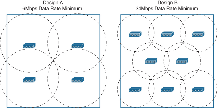
Figure 1-2 Example Data AP Deployments Comparing Minimum Data Rates
Reducing the AP cell size has one more effect. The number of clients associated to each AP is reduced, even if the clients are densely packed into the area. Therefore, a higher density of users can best be served by a higher density of APs. AP cell size and density are topics that are covered in greater detail in Chapter 5.
Voice/Video Deployment Model
If the application must send and receive data in a timely manner, it is known as a real-time application. Examples include voice over IP (VoIP), videoconferencing, and collaboration. You might have noticed a pattern—real-time applications involve voice and video; non-real-time applications include ordinary data.
Real-time applications require special consideration as you design, configure, and operate a wireless network. The following effects need to be minimized so that voice and video sessions can be heard and seen consistently, without interruption or corruption:
Latency: The amount of time required to deliver a packet or frame from a transmitter to a receiver
Jitter: The variance of the end-to-end latency experienced as consecutive packets arrive at a receiver
Packet loss: The percentage of packets sent that do not arrive at the receiver
Even minor congestion can disrupt applications that require communication in real time. Wireless devices that support voice or video communication will usually have a limit on the acceptable amount of jitter. As well, these devices will need seamless roaming so that the voice or video calls are not dropped or interrupted as the clients move around.
Voice applications are usually the most sensitive to adverse network conditions. This is because the audio at one end of the call must be encoded and transmitted at fairly regular intervals and without excessive delay. The audio will be buffered and reassembled into the original audio stream at the receiver. If the stream of frames is interrupted enough, the audio will sound strangely metallic or full of clicks and pops at the other end of the call. The audio might even be unintelligible. Video applications are sensitive, too, because portions of the visual field must be sent and received in real time. The goal is to update any changes in the video image quickly enough that the viewer at the far end sees continuous and fluid video stream. Brief delays or interruptions might not be as noticeable in a video stream as they are in an audio stream.
As an example, suppose a hospital intends to start using a mobile surveillance camera so that staff can keep watch over some patients. The camera device is designed to send live video and audio streams over the wireless network, qualifying it as a real-time application. Some of the relevant specifications for the camera device are listed in Table 1-5.
Table 1-5 Example Network Requirements for a Mobile Camera Device
Bandwidth |
1.5Mbps |
Latency |
Less than 150 ms |
Jitter |
Less than 30 ms |
Packet loss |
Less than 5% |
To minimize the factors that affect real-time applications, any adverse conditions in a wireless environment must be controlled. For example, a source of interference can cause packet errors that interrupt a voice or video stream. As packets are lost, they can be retransmitted and delayed, increasing latency and jitter. Other factors like poor radio frequency (RF) coverage, high channel utilization, and excessive collisions can also impede good data throughput and integrity. A real-time application can also experience problems if the client device takes too long to roam between APs. During the roaming process, wireless frames might get lost or delayed.
An AP deployment model that is focused on voice and video application traffic is not too different from a data deployment. Figure 1-3 shows a typical AP layout over an empty area. The AP cells are sized according to the receiver sensitivity levels of the voice devices at an acceptable data rate. With an emphasis on efficient roaming and thorough coverage, cells are commonly designed to support a minimum mandatory data rate of 12 or 24Mbps, with boundaries at −67 dBm.
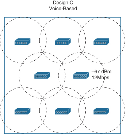
Figure 1-3 An Example Voice/Video AP Deployment
Location Deployment Model
Sometimes real-time location services (RTLS) are needed to automatically determine the physical location of wireless devices. RTLS can be used to track assets like healthcare equipment, to track rogue devices that might be causing problems on the network, to locate sources of wireless interference, and to track the locations of wireless clients within a building or campus.
A device is located by measuring its RSSI from several APs that can receive its signal, then using the multilateration technique to compute its physical location relative to the receiving APs. With 802.11-based devices, APs can easily receive frames transmitted by a device and relay the signal information on to an application that performs the location computations. If a single AP is used to determine a device’s location, as shown in the left portion of Figure 1-4, the distance from the AP to the device can be estimated by the RSSI and attenuation from free space path loss. However, the device could be located anywhere along a circle surrounding the AP because the RSSI would likely be constant anywhere on that circle. If more APs are added to the computation, as in the right portion of Figure 1-4, the number of possible locations can be greatly narrowed. Ideally, a wireless design should have enough APs distributed across the covered area such that a signal from any device location can be received by at least three APs.
If an object has no 802.11 capability, a small 802.11 RFID tag can be attached to it. The tag periodically transmits an 802.11 probe request frame to announce itself to any listening APs, allowing its location to be computed. Usually RFID tags transmit at the lowest mandatory data rate so that their signals can reach the greatest number of APs. Depending on their capabilities, some tags can send a payload of information to local-based servers to relay data about embedded sensors, the status of push buttons, and so on.
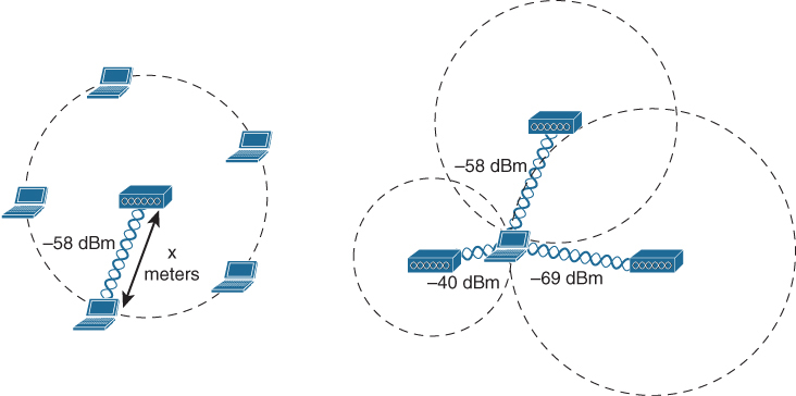
Figure 1-4 Determining the Location of a Wireless Device
Note
Be aware that RTLS is not a real-time application in the sense that streams of packets must be delivered efficiently. The “real-time” portion of its name means that objects can be detected and located in near real time. RTLS does not bring any latency, jitter, or packet loss requirements of its own and has very low bandwidth requirements, which could be notably different from the requirements needed to support real-time voice applications.
Typical location-based AP deployment models do not focus on any requirements other than RF coverage out to the edges of the floor area and device detection by multiple APs. Figure 1-5 shows a typical AP deployment. The APs are distributed in a familiar pattern over the coverage area, but notice that some of the APs are located around the perimeter of the coverage area. Even when a tracked device is located near an outer wall, its location can be computed accurately. The addition of APs around the perimeter causes a location-based model to require more APs than other deployment models.
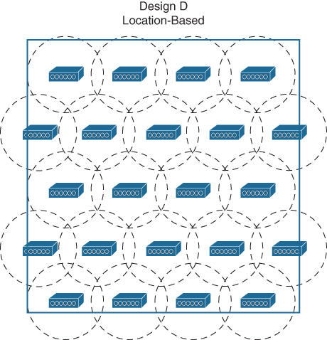
Figure 1-5 An Example Location-Based AP Deployment
AP Deployment Model Summary
You can use Table 1-6 to review the important attributes of each AP deployment model. Suppose a customer wants to use a combination of wireless devices that do not fit one specific model, such as laptops and tablets, along with wireless phones and RFID tags. Which model should drive your wireless design? You can combine all three to form a hybrid model that can support all of the devices. For example, all three models require RF coverage, so the APs should be distributed in a pattern that covers the entire area. To address the RFID tags, make sure to place some APs around the perimeter. To address both data and voice devices, you should choose a minimum mandatory data rate that can support both device types adequately and then size the AP cells accordingly. You will learn much more about the design process as you work through the remaining chapters of this book.
Table 1-6 AP Deployment Models and Their Attributes
Deployment Model |
Attributes |
|---|---|
Data |
|
Voice/Video |
|
Location |
|
Summary
This chapter described the main considerations needed as you begin to formulate a design for a wireless network. More precisely, you have learned the following:
How a formal design and lifecycle process can produce more organized and successful results
How different customers can have differing requirements for a wireless network
How wireless client devices and applications can place important requirements and constraints on a wireless design
How wireless security is a crucial aspect of a wireless design
How the layout of APs and their physical locations can influence and properly support data, voice and video, and location-based applications
Exam Preparation Tasks
As mentioned in the section “How to Use This Book” in the Introduction, you have a few choices for exam preparation: the exercises here, Chapter 18, “Final Preparation,” and the exam simulation questions in the Pearson Test Prep Software Online.
Review All Key Topics
Review the most important topics in this chapter, noted with the Key Topic icon in the outer margin of the page. Table 1-7 lists these key topics and the page numbers on which each is found.
Table 1-7 Key Topics for Chapter 1
Key Topic Element |
Description |
Page Number |
|---|---|---|
PPDIOO and PBM lifecycle processes |
8 |
|
Paragraph |
Collecting wireless client information |
11 |
Paragraph |
Wireless client form factors |
14 |
Paragraph |
Client density |
15 |
Paragraph |
AP types and antennas |
16 |
List |
Wireless client security criteria |
16 |
Paragraph |
Data AP deployment model |
18 |
List |
Parameters affecting voice and video applications |
19 |
Location-based AP deployment |
21 |
Define Key Terms
Define the following key terms from this chapter and check your answers in the glossary: