
Chapter 10
Implementing FlexConnect
This chapter covers the following topics:
Remote Office Wireless Deployment Modes: This section provides an overview of the various deployment options for enterprise wireless in remote locations, including Local mode (using a local controller at the branch), FlexConnect, Mobility Express, and Office Extend.
FlexConnect Overview and Requirements: This section discusses the details of the FlexConnect architecture, including modes of operation and AP and WAN requirements.
Implementing FlexConnect with AireOS: This section discusses how FlexConnect is configured and implemented, including the configuration of local versus central switching, the function of FlexConnect groups, and how roaming is accomplished within FlexConnect groups.
FlexConnect High Availability and Resiliency: This section provides an overview of FlexConnect survivability and high-availability options and how these are implemented.
FlexConnect ACLs: This section discusses the various uses of FlexConnect ACLs and how these are used to achieve split tunneling and map SSIDs to VLANs.
FlexConnect Smart AP Image Upgrades: This section discusses how AP software upgrades are accomplished using smart software upgrades in a FlexConnect environment.
Implementing FlexConnect with IOS-XE Controllers: This section introduces the IOS-XE controller and how FlexConnect may be implemented leveraging many of the same concepts introduced earlier in this chapter.
A Summary of FlexConnect Best Practices Recommendations: This section reviews the best practices discussed in this chapter, with application to both AireOS and IOS-XE controllers.
Office Extend: The final section gives an overview of the Office Extend mode for remote deployments and how these are configured in the wireless controller.
This chapter covers the following ENWLSI exam topics:
1.1 Deploy FlexConnect components such as switching and operating modes
1.2 Deploy FlexConnect capabilities
1.2.a FlexConnect groups and roaming
1.2.b Split tunneling and fault tolerance
1.2.c VLAN-based central switching and Flex ACL
1.2.d Smart AP image upgrade
1.3 Implement Office Extend
Deployment of enterprise wireless in branch offices introduces new challenges that are not encountered when deploying wireless in a centralized campus network. In a campus environment, the controller is typically deployed on a network that has reliable, high-bandwidth, and low-latency access to the APs it manages. In these environments, both the control plane traffic and the data plane traffic of the AP are managed by the controller. This has obvious architectural benefits in that it promotes centralization of policy and systematic control of client traffic entering or leaving the wireless network. Additionally, this mode allows the controller to dynamically optimize the AP’s RF settings and interactions using radio resource management (RRM) and it provides a central way to manage QoS to the wireless network.
However, when wireless networks are expanded to branch or remote locations, the use of a centralized wireless controller is not always practical. This is primarily due to the increased latency, jitter, and packet loss caused by backhauling the wireless traffic over the WAN to a central location, not to mention possible issues with WAN circuit reliability. For example, if a remote office was to have only a handful of APs serving a few employees, bringing all client wireless back to a centralized point over the WAN would not only be inefficient, but it would also introduce latency issues that would negatively impact certain traffic types, especially real-time applications, including voice and video. Also, consider a situation where wireless clients at a remote branch need access to a local file server or printer at the same location. Using a centralized wireless controller means all application traffic inside the CAPWAP tunnel must be backhauled over the WAN to the controller, and it is then tromboned back again to the branch over the same WAN—essentially forcing data plane traffic to traverse the WAN twice (and doubling the latency) when the service was sitting nearby on the local LAN in the first place. Clearly, this is inefficient and can cause both user satisfaction and application performance issues, not to mention unnecessarily burdening the WAN with traffic it doesn’t need to see.
This chapter discusses various methods to solve this problem, with a primary focus on FlexConnect. All relevant exam objectives are discussed, including FlexConnect architecture and capabilities, along with the basic requirements needed to deploy FlexConnect. In addition, this chapter introduces advanced implementation topics, including the use of ACLs to selectively map SSIDs to VLANs and map specific VLANs to be either locally or centrally switched (split tunneling). FlexConnect resiliency and high availability are also introduced, as well as how FlexConnect APs can be efficiently upgraded over the WAN. Both the AireOS controller and IOS-XE controller implementations are discussed.
The chapter concludes with a discussion of Office Extend as way to offer wireless services and extend the corporate enterprise network to a single AP.
“Do I Know This Already?” Quiz
The “Do I Know This Already?” quiz allows you to assess whether you should read this entire chapter thoroughly or jump to the “Exam Preparation Tasks” section. If you are in doubt about your answers to these questions or your own assessment of your knowledge of the topics, read the entire chapter. Table 10-1 lists the major headings in this chapter and their corresponding “Do I Know This Already?” quiz questions. You can find the answers in Appendix D, “Answers to the ‘Do I Know This Already?’ Quizzes and Review Questions.”
Table 10-1 “Do I Know This Already?” Section-to-Question Mapping
Foundation Topics Section |
Questions |
|---|---|
Remote Office Wireless Deployment Modes |
1 |
FlexConnect Overview and Requirements |
2–3 |
Implementing FlexConnect with AireOS |
4–5 |
FlexConnect High Availability and Resiliency |
6–7 |
FlexConnect ACLs |
8 |
FlexConnect Smart AP Image Upgrades |
9 |
Implementing FlexConnect with IOS-XE Controllers |
10 |
Office Extend |
11–12 |
1. FlexConnect APs have been deployed in a remote branch office. Due to a network outage at the central site, the controller has become unavailable, forcing the APs to go into standalone mode. Which services are lost on the access points while in standalone mode?
Client authentication services
RRM
Roaming
No services are lost. The FlexConnect APs are designed to function in a semi-autonomous mode.
2. A company is looking to deploy 10 FlexConnect APs in a medium-sized branch location. The branch location will have a variety of wired video conference units, but otherwise the employees are expected to use wireless for data services. What are the minimum design requirements to be aware of?
Minimum bandwidth should be 640Kbps and the latency should be less than 300 ms.
Latency and bandwidth are not a concern because FlexConnect APs are designed to work autonomously from the controller.
The minimum bandwidth should be 128Kbps and the latency should be less than 300 ms.
In compliance with ITU-T recommendations for voice, one-way latency must be under 150 ms and jitter must be no more than 30 ms.
3. An engineer is planning to deploy a new FlexConnect AP. The AP is converted to FlexConnect mode, the native VLAN is configured, and the WLAN-to-VLAN mapping has been correctly configured. What critical configuration step has been overlooked?
The AP must be rebooted.
The AP must be added to a FlexConnect group.
The FlexConnect WLAN has not been configured for local switching.
VLAN trunking has not been enabled on the AP.
4. Seamless roaming is desired at a branch office. Which important feature must be configured to ensure this works correctly?
802.11r Fast Transition (FT)
CCKM/OCK local key caching
Local authentication
5. A FlexConnect group has been enabled on the branch wireless network. Due to limited WAN bandwidth, it was noticed that it takes longer than expected for clients to authenticate to the WAN. What are steps the engineering team can take to improve WLAN performance at the branch? (Choose two.)
Turn on local authentication caching on the FlexConnect APs.
Enable CAPWAP message aggregation.
Configure the WLAN to use WPA-PSK.
Enable local authentication for this WLAN.
Extend the key refresh interval.
6. What is a key requirement to enable split tunneling on a FlexConnect AP?
The centrally switched WLAN must have the locally switched option selected.
NAT/PAT must be configured to allow centrally switched traffic to access the local VLAN.
An ACL must be used for split tunneling to take effect.
Split tunneling must be configured at the FlexConnect group level.
7. The Smart AP Image Upgrade option has been selected, but no master has been configured. What will happen?
The image upgrade will fail and the APs will continue to wait until a master is properly configured.
A master AP will be automatically selected based on the lowest MAC address.
The APs will bypass the option until a master is configured and will simply download the new image from the controller directly.
The APs will elect a master among themselves based on the lowest IP address.
8. How are Office Extend access points able to securely communicate with the controller?
IPSec encryption of the CAPWAP tunnel must be enabled through the security page on the controller.
DTLS is enabled by default on the OEAP.
FlexVPN is enabled by default on the OEAP.
Encryption is not natively supported—the CAPWAP tunnel must be externally protected through the use of a VPN router.
9. A new access point is going to be converted to OEAP mode. What step must be taken to convert the AP to OEAP mode?
The AP must first be converted to FlexConnect mode, then to OEAP mode.
An AP cannot be converted to OEAP mode in the field—OEAP must be configured from the factory.
As with other AP modes, it is converted directly to OEAP mode from the wireless tab in the controller.
An AP can only be converted to OEAP mode by overriding the default settings in the CLI.
Foundation Topics
Remote Office Wireless Deployment Modes
The alternative to deploying centrally controlled APs (where the data plane is switched by the controller) is to deploy the APs in one of four ways:
Deploy a local controller at each branch: While the deployment of local controllers at each branch will offer the exact same services to the branch that are available at the central location, there are certain downsides to this approach. For example, the deployment of a local controller at each branch will involve added cost and management overhead, especially if redundant controllers are used. Continual maintenance of software updates of a large number of controllers is also a disadvantage that needs to be considered. For example, if a company has 6,000 branches, this implies adding at least 6,000 new controllers to the network, including the network infrastructure required to connect the controllers at each branch location (note that controllers can be deployed as either a standalone appliance or as a virtual machine on a server). Practically speaking, if the number of APs required at a branch office is large, it might make perfect sense to deploy a local controller—in fact, in some cases there may be no alternative other than deploying a local controller at a large branch. However, if the number of APs is low to moderate, using a controller per branch is generally considered suboptimal.
FlexConnect at the branch: FlexConnect is a hybrid architecture that offers a compromise where the control plane of office APs is still managed by a centralized controller, but the data can be locally switched at the AP on a per-SSID basis. This allows the AP to deliver most of the same services available in centralized mode, but the controller does not switch data plane traffic or terminate the data plane CAPWAP tunnels. As the name implies, FlexConnect is flexible in that the administrator can choose which SSIDs are locally switched versus which ones are centrally switched at the controller. Note that the deployment of FlexConnect is the main focus of this chapter.
Mobility Express at the branch: An alternative to using a dedicated local controller at each branch is to deploy the APs in Mobility Express (ME) mode. ME is essentially the full controller functionality but deployed as software locally on an AP. In other words, instead of deploying a standalone controller at the branch site, in ME mode one of the APs takes on the role of controller for the other APs at the same location. Similar to a dedicated controller, the ME master AP terminates the CAPWAP control plane tunnels for the other APs and behaves much like a centralized controller supporting FlexConnect, with obvious performance limitations because the AP needs to function as both a controller and an AP at the same time.
One disadvantage of ME is that it involves a certain amount of overhead, as each branch will have an independent controller-on-AP that needs to be managed independently (meaning you are back to managing a different controller per branch—with the advantage being that you don’t need to purchase any dedicated controller hardware at the branch offices).
Note
Mobility Express is not discussed in depth in this chapter.
Office Extend on the APs: In situations where a small branch office only requires a single AP, Office Extend is a simple way to connect remote users to the corporate network. As the name suggests, Office Extend is a way for the corporate network to be extended to remote users via an encrypted VPN tunnel directly from the AP to the controller.
It is clear that several options exist to extend wireless services to remote and branch offices. The decision of which to deploy involves several factors, including the following:
Is communication between the branches and the corporate network reliable, and what is the latency profile?
Do the branch users require real-time applications, such as voice and video, or are they limited to data-only communications?
Does the organization have a lean IT team?
What is the number of branches involved?
How many employees are at each branch, and how many APs are required per branch?
Do branch offices support local Internet access, or are the branches connected to the core network in a hub-and-spoke fashion?
Scalability of APs at a branch can often be a limiting decision as to which architecture to use. For example, Mobility Express supports either 50 or 100 APs, depending on the type of master AP used, and FlexConnect can support a maximum of 100 APs per group (but multiple groups may be used). Thus, if the size of the branch exceeds this number of APs, either a controller will be required at the branch, or multiple independent ME or FlexConnect groups will need to be deployed. The downside to deploying multiple independent ME or FlexConnect groups is that certain functions will be lost between groups. For example, in a large centralized campus, the controller supports functions such as RRM and seamless roaming between APs; however, if multiple ME and FlexConnect groups are in use, RRM and roaming will not be possible between group boundaries. In this case, the remote location is better served by a local controller.
FlexConnect and Mobility Express both offer similar services to remote branch APs, so when should one be used over the other? Generally, FlexConnect can be used in branch office scenarios when WAN connectivity to the controller is reliable and meets the minimum requirements for controlling FlexConnect APs. On the other hand, Mobility Express is typically used when the WAN is unreliable, the central controller is either too far away (the latency is high), or the bandwidth is so constrained that FlexConnect APs are not able to function correctly for a prolonged period. Mobility Express offers the advantage of having a full suite of controller capabilities local to the branch, running directly on one of the APs (meaning a standalone controller is not required). The downside of ME is that it involves the use of more controllers that must be managed and involves greater support from the IT staff.
The following section reviews the FlexConnect architecture and deployment requirements.
FlexConnect Overview and Requirements
FlexConnect is a method to connect APs and wireless users at a remote or branch office through the use of a centralized controller. Unlike centralized wireless deployments, where all wireless data plane traffic is sent to the controller via CAPWAP, FlexConnect allows wireless traffic to be locally switched and processed directly by the branch AP. In effect, local switching of traffic gives the FlexConnect AP some autonomy from the controller where services such as security, roaming, and QoS can be supported independently without oversight from the controller.
While FlexConnect is designed to locally switch certain SSIDs, it is also flexible in that some SSIDs can be centrally switched if desired. For example, if there is a requirement to have certain traffic switched centrally (such as traffic that needs to be processed through a central firewall), then these SSIDs may be brought back over CAPWAP and are centrally switched by the controller. The key point is that FlexConnect APs are able to support both locally and centrally switched WLANs on the same AP simultaneously.
Figure 10-1 illustrates a FlexConnect AP that locally switches traffic from a wireless client to a printer on one SSID, while a different client associated to a different SSID on the same AP sends all wireless traffic back to the controller at the corporate office where it is centrally switched.

Figure 10-1 A FlexConnect AP Deployed at a Branch Locally Switches One SSID While Another Is Centrally Switched
Modes of Operation
FlexConnect APs operate in one of two modes: connected mode or standalone mode. Connected mode refers to a state when the AP is able to actively reach the controller (the CAPWAP control channel between controller and AP is up). Standalone is a fallback mode when the AP is no longer able to reach the controller.
The normal operation of FlexConnect APs should be connected mode, where the controller provides key services, including centralized authentication, client profiling, and RRM. It is expected that in most cases the AP will run in this mode; however, if the AP loses connectivity to the controller, it then goes into standalone mode. In standalone mode, the AP still functions, allowing packets to be locally switched and clients can still access the wireless network; however, certain high-touch services are temporarily lost, such as RRM and centralized authentication of clients.
For example, if there was a WAN disruption that prevented an AP from communicating with its controller, but Internet access was still available, the APs would simply revert to standalone mode during the service disruption and would continue to function normally, with the exception that new clients requiring central authentication would not be able to associate to the wireless network (unless local authentication was enabled). Otherwise, all locally switched traffic would continue to be switched locally and users will not even notice the change in AP mode. Note that it is also possible to configure FlexConnect APs to use local authentication in the event of a WAN failure.
While in standalone mode, the following features are not available to the AP:
Client web authentication
Any centrally switched SSIDs
RRM
IPv6 mobility
Native profiling
Policy classification
Service Discovery Gateway
Configuration updates
Wireless intrusion prevention system (WIPS)
For a complete list of features supported in connected versus standalone mode, see the feature matrix in the “References” section at the end of this chapter.
Note
802.11ac Wave 2 and 802.11ax (Wi-Fi 6) APs have a different feature matrix, which can be found in the “References” section at the end of this chapter.
WAN Requirements for FlexConnect
Although FlexConnect APs are designed to switch traffic locally, they leverage key control capabilities from the controller, including configuration management and RRM. Similar to local mode, control of FlexConnect APs is accomplished through the CAPWAP control tunnel. Thus, for FlexConnect APs to function correctly in connected mode, they must meet minimum latency and bandwidth requirements, depending on how the AP is used. Table 10-2 summarizes the bandwidth and latency requirements for APs deployed supporting data-only clients, data + voice clients, and APs deployed in monitor mode.
Table 10-2 A Summary of FlexConnect WAN Requirements
Deployment Type |
WAN Bandwidth (Min) |
WAN RTT Latency (Max) |
Max APs per Branch |
Max Clients per Branch |
|---|---|---|---|---|
Data |
64Kbps |
300 ms |
5 |
25 |
Data |
640Kbps |
300 ms |
50 |
1,000 |
Data |
1.44Mbps |
1 sec |
50 |
1,000 |
Data + Voice |
128Kbps |
100 ms |
5 |
25 |
Data + Voice |
1.44Mbps |
100 ms |
50 |
1,000 |
Monitor |
64Kbps |
2 sec |
5 |
N/A |
Monitor |
640Kbps |
2 sec |
50 |
N/A |
As noted in Table 10-2, WAN bandwidth requirements are dependent on the number of APs and clients in use at the branch. The relationship between bandwidth and the number of APs is generally linear, meaning as the number of APs and clients increases, so follows the minimal bandwidth requirement. The minimum latency requirement is generally constant, depending on the wireless applications in use (for data only the minimum latency is 300 ms, and for data + voice the minimum latency is 100). If these requirements are not met, the APs may fall back into standalone mode and certain services will be lost until the network is restored to threshold limits.
When the FlexConnect APs are deployed in monitor mode, the latency requirements are eased since these APs do not need to centrally authenticate users and require less administrative overhead from the controller.
Implementing FlexConnect with AireOS
FlexConnect is a special mode that allows APs to switch traffic locally and to act in a semi-autonomous mode from the controller. At a high level, the steps involved in configuring a FlexConnect AP in an AireOS controller are as follows (configuration in an IOS-XE controller is discussed later):
Change the mode of the AP to FlexConnect mode.
Configure FlexConnect local switching on the AP.
Configure the native VLAN on the FlexConnect AP and the attached Ethernet switch and configure the correct WLAN-to-VLAN mapping.
These three steps will be discussed in the following sections.
Convert the AP to FlexConnect Mode
The first step is to change the AP mode to FlexConnect. In the AireOS controller menu, navigate to Wireless > Access Point > (AP_NAME) > AP Mode and choose FlexConnect. When the AP mode is changed from local to FlexConnect, it does not need to reboot (however, when it is changed back from FlexConnect to local mode, it requires a reboot and displays the following error message: “Warning: Changing AP Mode will reboot the AP and will rejoin the controller after a few minutes. Are you sure you want to continue?”).
Figure 10-2 illustrates how the AP mode is changed.

Figure 10-2 Changing the AP to FlexConnect Mode
Configure the Locally Switched WLANs
The second step is to configure local switching on the WLANs that will be used at the branch. Select the SSID that will be locally switched in the WLANs > (WLAN Name) > Advanced menu. Navigate to the FlexConnect menu and select FlexConnect Local Switching. This now enables the WLAN to be locally switched at the FlexConnect AP. Figure 10-3 illustrates this configuration step.
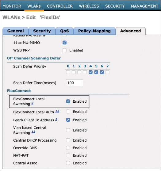
Figure 10-3 Enabling Local Switching for the WLAN
When an AP is configured in FlexConnect mode, it is expected that at least one WLAN will be locally switched. While centrally switched WLANs are inherited by default on the FlexConnect AP, WLANs that are locally switched must be specifically configured as distinct from the centrally switched WLANs. In this way, a FlexConnect AP may simultaneously support both centrally and locally switched WLANs. In fact, it is also possible to create multiple SSIDs with the same name but with different switching profiles. This is common in guest scenarios where some sites may require locally switched SSIDs and other sites may want centrally switched SSIDs, both having the same SSID name.
Configure the Native VLAN and WLAN-to-VLAN Mapping
Once a locally switched SSID/WLAN is configured, the next step is to configure the native VLAN of the AP and the local WLAN-to-VLAN mapping. When APs are configured in local mode, they simply bridge all 802.11 traffic back to the controller over CAPWAP and the controller is then responsible for mapping the WLAN to the correct VLAN where it is sent over an 802.1Q VLAN trunk connected to the controller’s local switch. Thus, VLAN trunking is not required on APs in local mode.
However, in the case of FlexConnect, the locally switched traffic must emerge directly from the AP onto the correct VLAN, meaning the AP and its connected switch must both be configured for 802.1Q VLAN trunking. On the Wireless menu in the AireOS controller, a FlexConnect sub-tab will appear for the AP once the mode has been changed to FlexConnect. This can be found by navigating to Wireless > Access Point > (AP_NAME) > FlexConnect. Figure 10-4 illustrates the FlexConnect sub-tab.
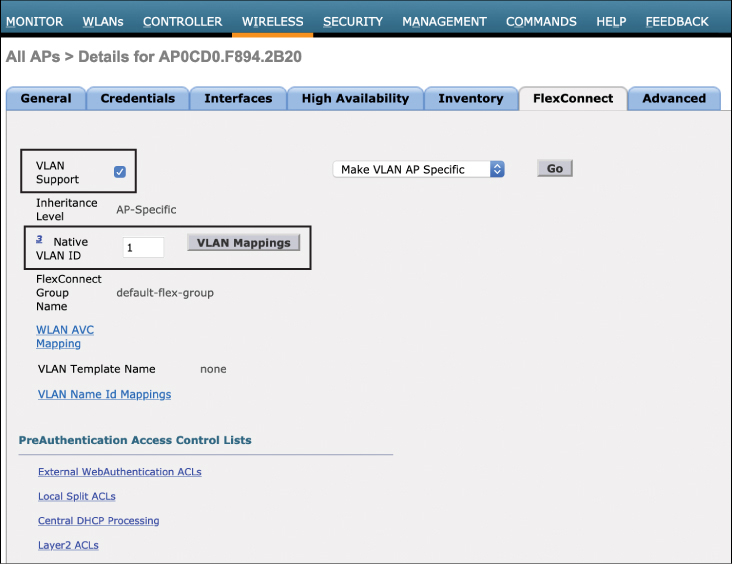
Figure 10-4 Configuring the Native VLAN on the FlexConnect Sub-Tab
The first feature that must be configured is the VLAN Support option. This option enables 802.1Q trunking on the AP. Note that the VLAN IDs and trunk configuration on this page must be matched on the switch connecting to the AP (this includes the correct native VLAN, allowed VLAN IDs on the trunk, and trunking mode). Once the Native VLAN option has been configured, select the VLAN Name Id Mappings option. The VLAN Name ID Mappings configuration page is shown in Figure 10-5.
From here, the specific WLAN-to-VLAN mappings can be configured. This involves mapping the WLAN ID to the correct VLAN ID that is used on the 802.1Q trunk. Repeat this configuration step for all locally switched VLANs (but not centrally switched WLANs). Also note in Figure 10-5 that a list of centrally switched WLANs is displayed for each AP. These are the WLANs that have been left in the centrally switched default state. To add any WLANs to the mapping, they must first be changed to “locally switched” in the WLANs configuration page, as discussed earlier.
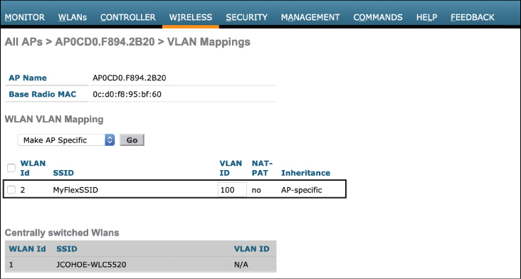
Figure 10-5 Configuring the WLAN-to-VLAN Mapping
Once the native VLAN and WLAN-to-VLAN mappings have been configured, the next step is to ensure the connected switch mirrors the VLAN trunking configuration. In Example 10-1, the native VLAN is left as 1 (which is the default), and only VLAN 100 is allowed on the trunk (VLAN 100 is the mapping of the locally switched WLAN).
Example 10-1 Configuring the Matching VLAN Trunk Details on the Connected Switch
interface GigabitEthernet1/0/13
 switchport trunk encapsulation dot1q
 switchport trunk allowed vlan 100
 switchport trunk native vlan <native VLAN number>
switchport mode trunk
By default, VLAN 1 is the default native VLAN in Cisco switches and does not need to be specifically configured. If a different VLAN is used for the native, then this must be configured, as shown in Example 10-1.
The configuration steps shown thus far need to be performed on a per-AP basis in the controller. However, if there are hundreds or thousands of APs in use, this approach clearly does not easily scale. The next section will discuss how FlexConnect groups are used to improve functionality and speed up bulk configuration tasks.
Implementing FlexConnect Groups
FlexConnect groups are responsible for sharing services between APs in the group. For example, the following services are shared within a FlexConnect group:
Cisco Centralized Key Management (CCKM) / Opportunistic Key Caching (OKC) fast roaming keys
Local/backup RADIUS server keys
Local EAP (Extensible Authentication Protocol) authentication
FlexConnect AVC (Application Visibility and Control)
AAA-Override for local switching
At a high level, FlexConnect groups are a way for APs in the group to inherit common configuration attributes without you having to configure each individual AP. They also play a key role in supporting seamless roaming between APs within the group. By way of contrast, for SSIDs in central switching mode (or on APs in local mode), the controller is responsible for sharing the CCKM/OCK keys between APs, thus supporting high-speed roaming between APs and overcoming the problem of client reauthentication each time a client roams. FlexConnect groups are designed to accomplish the same capability for locally switched WLANs.
To illustrate how FlexConnect works, consider how it handles CCKM/OCK key sharing. When a wireless client associates and authenticates to a WLAN, the RADIUS server allocates two keys—one for the client and one for the AP. As the client roams between APs, the key from the first AP is transferred to the next, so the client doesn’t need to reauthenticate. When the AP is in connected mode, the controller stores these keys and pushes them to the new AP as the client roams. If this model were used for FlexConnect, two problems would be encountered. First, pushing keys to an AP over the WAN each time a client roams will likely introduce unacceptable latency that results in a slower roam times, making it noticeable on the client side, especially if real-time applications are in use. The second problem is when the controller becomes unavailable and the FlexConnect APs go into standalone mode. In this case, roaming will require reauthentication as the client attempts to move from one AP to another. However, because the controller is no longer available and reauthentication is not possible, the roam will fail (unless a local backup RADIUS server is deployed).
While in connected mode, the controller shares the keys with the APs in the FlexConnect group, creating a local roaming domain where the APs no longer need to retrieve the keys from the controller each time a client roams. This also solves the problem when the controller becomes unavailable and the APs are in standalone mode. In this case, the APs in the FlexConnect group already have the keys, and clients are able to roam seamlessly without the need to contact the controller. However, if an AP boots up in standalone mode where it has not yet seen the controller, it will not have access to the CCKM/OCK keys to become part of the roaming domain, and seamless roaming will not be possible until connected mode is restored for that AP.
Note
The concept of AP groups should be fairly familiar to you by now. AP groups are a way to create a logical grouping of APs that deliver a similar set of Wi-Fi services. It is important to note that AP groups and FlexConnect groups are not mutually exclusive, meaning that a branch AP may be part of both an AP group and a FlexConnect group.
FlexConnect groups can be created in the Wireless > FlexConnect Groups menu. Figure 10-6 illustrates the creation of a new FlexConnect group called FLEX-1.

Figure 10-6 Creation of a FlexConnect Group
When first configured, all FlexConnect APs are part of a group called “default-flex-group.” While certain configuration options can be configured in the default group, this group does not share authentication keys among other members of the group, meaning the group does not support seamless roaming, so it is recommended to create a FlexConnect group at each remote location.
Figure 10-7 illustrates the configuration options for a FlexConnect group.

Figure 10-7 Configuration of the FlexConnect Group
In the FlexConnect configuration menu, the group can be given configuration characteristics that are inherited by all APs assigned to the same group. These include attributes for Local Authentication, Image Upgrade, ACL mapping, Central DHCP, WLAN VLAN mapping, and WLAN AVC mapping.
Once the FlexConnect group has been created and configured, the final step is to add APs to the group. This can be done by selecting the FlexConnect AP option on the General menu and then adding selected APs to the group (as shown in Figure 10-7). Only APs that have been configured in FlexConnect mode are listed as available options that can be added to the FlexConnect group (refer Figure 10-2), and APs may only be part of one FlexConnect group at a time.
Due to scalability limitations related to authentication key caching, FlexConnect groups are limited to no more than 100 APs per group. Additionally, the total number of configurable groups varies with the size and capacity of the controller used (for example, the WLC 5520 supports a maximum of 1,500 FlexConnect groups).
FlexConnect High Availability and Resiliency
The following section describes methods to ensure resiliency of FlexConnect in the event of WAN failure or other types of service degradation where access to the controller is impaired or lost.
FlexConnect Resiliency Scenarios
One of the most common FlexConnect failure scenarios is a complete loss or serious degradation of the WAN, thus impairing the CAPWAP control channel. When WAN connectivity is degraded to the point where connectivity to the controller is lost, FlexConnect APs at remote locations immediately go into standalone mode. While in standalone mode there is no impact to locally switched SSIDs; however, all clients that are part of centrally switched SSIDs will be disconnected. While wireless services can continue uninterrupted for clients already associated on locally switched SSIDs, the ultimate goal is to reestablish connectivity to the controller as quickly as possible so all services can be restored. Until then, services such as RRM and WIPS will be unavailable.
Another scenario that impacts resiliency is a failure of the central controller itself. Chapter 9, “Designing High Availability,” discusses various controller high-availability scenarios, but it is worth taking a brief look at how these options interact with FlexConnect APs.
One common resiliency scenario for controllers is the N+1 scenario, where multiple active controllers may use a common backup controller that can be used in the event that any of the active controllers has a failure. In this scenario, when the primary controller fails, FlexConnect APs will immediately go into standalone mode and will begin looking for a backup controller. During this period of disconnection, all centrally switched clients will be disconnected from the FlexConnect APs. When the APs find a backup controller, they immediately begin to resync with the controller, and any clients that need access to centrally switched SSIDs will be reassociated. During this transition period, locally switched clients are not affected and will not even notice the service disruption.
Another common controller resiliency model is Stateful Switchover (SSO). In this mode, the controllers are deployed as a 1:1 pair, where the running state of the active controller is replicated to a dedicated backup controller. In this scenario, the AP database, including all information related to FlexConnect APs, their centrally switched SSIDs, and client run state, is actively synchronized on the backup controller. During the failure of the active controller to the stateful backup, FlexConnect APs remain in connected mode and do not enter standalone mode, meaning centrally switched SSIDs will not go down.
AAA Survivability
When a FlexConnect AP goes into standalone mode due to a WAN failure, actively connected clients continue to function and may roam seamlessly from one AP to another within the FlexConnect group. However, any new clients that wish to associate to the locally switched WLAN during this time will be unable to because the AAA server at the central location is unavailable.
One resiliency option to deal with this situation is to offer a backup AAA server at the remote location that is accessible by the FlexConnect group. Figure 10-8 illustrates this model.

Figure 10-8 Clients Authenticate Against a Local Backup AAA Server When the Central AAA Server Becomes Unavailable Due to a WAN Failure
With local authentication enabled, the backup RADIUS server is only used when APs go into standalone mode—that is, when the APs are in connected mode, the local backup AAA server is not used. When the local backup AAA is used for authentication by FlexConnect APs, the authentication keys are distributed to all APs in the FlexConnect group in the same way they are when a centralized AAA server is used. In this way, even when a local backup RADIUS is in use, new clients are still be able to roam without being asked to reauthenticate.
Configuring AAA Survivability
Figure 10-9 illustrates how local authentication in the FlexConnect group may be configured. As can be noted in Figure 10-9, the Enable AP Local Authentication option needs to be selected first, then the primary AAA configuration is added. Also note that a secondary backup AAA server can be configured at the remote site if desired.
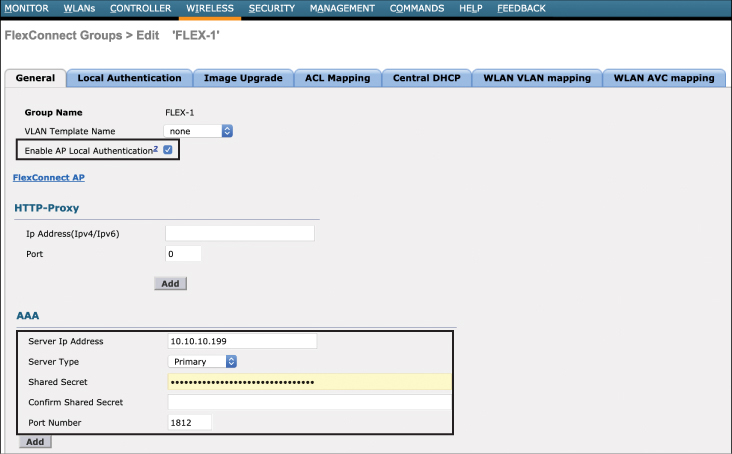
Figure 10-9 Configuring Local Authentication in the FlexConnect Group
Note
As previously discussed, the backup AAA server is only used when the WAN is down and the central AAA server is unavailable. Thus, while Flex APs are in connected mode, the central AAA server is used for all authentications. However, there may be cases where local authentication is desired, even when the WAN is up and the central RADIUS server is accessible. In cases like this, it is also possible to configure the FlexConnect APs to only use a local authentication server. To configure this in AireOS, select the option under WLAN > (WLAN ID) > Advanced and select the FlexConnect Local Auth option.
CAPWAP Message Aggregation
One final tool to help with branch resiliency is an option called “CAPWAP Message Aggregation.” When the controller communicates to an AP to perform a certain control task, such as authenticating a client, making radio changes through RRM, or any other type of configuration changes, it is sent to the AP through the CAPWAP control channel. As part of CAPWAP’s built-in resiliency mechanism, it uses an application-level acknowledgment for each message that is sent between the controller and each AP. However, in a very busy WLAN scenario where clients are continually roaming, rogues are being detected, and the RF environment is fluctuating, the performance of CAPWAP can suffer because each message needs to be acknowledged before the next can be sent. In a WAN that is already suffering latency and packet loss issues, this can further undermine the performance of the CAPWAP control traffic, causing a noticeable effect on wireless performance at the branch.
An efficient solution to this problem is to aggregate CAPWAP control messages for the APs. Figure 10-10 illustrates a “before and after” scenario of a controller that has CAPWAP message aggregation enabled.

Figure 10-10 A Before and After Comparison When CAPWAP Message Aggregation Is Enabled
As can be seen in Figure 10-10, CAPWAP message aggregation allows multiple control messages to be sent in bulk from the controller to the AP, and then the AP returns a bulk acknowledgment back to the controller (for example, Ack 1 and Ack 2 are sent together rather than in separate messages). In a branch office with limited WAN connectivity, congestion of CAPWAP control messages can be one of the main causes of slow client authentication time. Thus, message aggregation has the effect of greatly improving both the transmission of the control messages and returning their acknowledgment; thus, it is recommended this feature be enabled at all times.
CAPWAP message aggregation may be enabled with the following command in AireOS (note that this feature is enabled by default in IOS-XE and is enabled by default in AireOS 8.6 and later):
config advanced capwap-message-aggregation enable
FlexConnect ACLs
A useful design characteristic of centralized wireless systems is that the controller can function in a central place to enforce security controls for all traffic as it leaves the network. For example, there may be certain SSIDs that require central security policy enforcement by a firewall. If using centrally switched SSIDs, wireless traffic can be mapped to a VLAN on the controller that is directly connected to a central firewall. In this way, a centralized method is employed both to protect the wireless clients and also to restrict what they can access. In a distributed model where FlexConnect APs at branches are configured for local switching, this level of control is decentralized and is more difficult to enforce. In order to provide security for locally switched networks, FlexConnect ACLs may be used.
FlexConnect ACLs are centrally configured on the controller and then automatically downloaded to the APs. An AireOS controller supports a maximum of 512 ACLs, and up to 96 ACLs can be downloaded to a single FlexConnect AP, with a maximum of 64 rules per ACL. FlexConnect ACLs may be used in four different ways:
VLAN ACLs: These are primarily used as security ACLs that are applied on the ingress or egress direction on the wireless interface of the AP and may use either an IP address or a URL to match traffic.
Webauth/Webpassthrough ACLs: Webauth ACLs are used for Webauth/Webpassthrough SSIDs that have been enabled for FlexConnect local switching. This is used as a pre-authentication ACL, which allows client traffic to reach a redirect server.
Web Policy ACLs: Web Policy ACLs are used for conditional web redirect, splash page redirect, and central WebAuth scenarios (discussed in greater detail in Chapter 15, “Security for Wireless Client Connectivity”).
Split Tunnel ACLs: These are used when centrally switched traffic needs to access resources locally.
This section examines two of these use cases: VLAN ACLs and split tunnel ACLs.
VLAN ACLs
As with other ACLs on the controller, FlexConnect VLAN ACLs are first configured on the Security menu in the AireOS controller (they may also be configured from the wireless menu). Cisco controllers support both IPv4 and IPv6 security ACLs. Figure 10-11 illustrates the creation of a security ACL that will be used for FlexConnect.
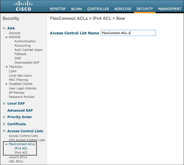
Figure 10-11 The Creation of VLAN ACLs to Be Used for FlexConnect
Figure 10-12 provides an example of an ACL with its associated rules that will be applied to a FlexConnect group. Note that both IP-based and URL-based rules may be added to an ACL.
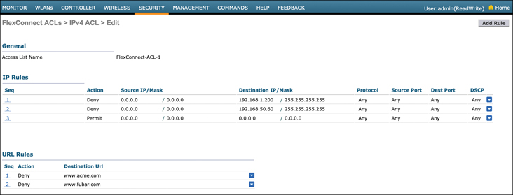
Figure 10-12 The FlexConnect ACL Rules
Once an ACL has been created, it needs to be added to a FlexConnect AP or the FlexConnect group. To add the VLAN ACL to a FlexConnect group in AireOS, navigate to wireless > FlexConnect > (name) > ACL Mapping > AAA VLAN-ACL mapping. From here, add the VLAN ID that the ACL is being added to and select the ingress and egress ACL options from the pull-down menu. Once this is done, click Add (see Figure 10-13).

Figure 10-13 Adding the VLAN ACLs to a FlexConnect Group
FlexConnect Split Tunneling (Using the Split ACL Mapping Feature)
Another common use case in FlexConnect is where clients are part of centrally switched WLAN but require access to local resources. Because these clients are centrally switched, they can’t access these resources without having to traverse the CAPWAP tunnel over the WAN, be switched through the controller, and then return to the branch over the same WAN once again (incurring extra latency along the way). The FlexConnect split tunnel feature allows centrally switched clients to access local resources without having to traverse the CAPWAP tunnel.
With split tunneling enabled, an ACL is applied on the FlexConnect APs to examine matching packets to determine if they should be sent over the CAPWAP tunnel toward the controller or should exit the WLAN onto a specific local VLAN directly from the AP. To do this, split tunneling uses a NAT/PAT feature along with the ACL to bridge traffic directly onto the correct local LAN. Split tunneling uses the AP’s management IP address as the NAT/PAT address.
The steps to configure split tunneling are as follows:
Step 1. Identify the centrally switched WLAN that should have access to a local service. Ensure that this WLAN is not configured for local switching.
Step 2. Configure the Flex ACLs that will be used to identify traffic that will be split-tunneled. The source address belonging to the centrally switched subnet and the destination address should be on the local subnet. Figure 10-14 illustrates a Flex ACL configured to allow the 192.168.10.0/24 subnet access to 10.0.10.5/32 on the local LAN.
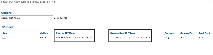
Figure 10-14 Configuring a FlexConnect ACL for Split Tunneling
Step 3. Configure local split tunneling on a per-AP or per-FlexConnect group basis. This step is configured by navigating to wireless > FlexConnect > (name) > ACL Mapping > WLAN-ACL mapping. Figure 10-15 illustrates adding the split tunnel configuration to a Flex group.
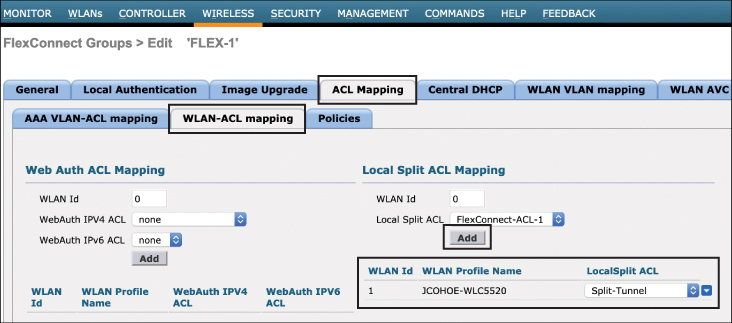
Figure 10-15 Adding the Split Tunnel ACL to the FlexConnect Group
FlexConnect Smart AP Image Upgrades
Upgrading APs over the WAN can be a challenge when there are a large number of APs and when the WAN bandwidth is constrained. For example, imagine a situation where a company has 1,000 branch offices, with an average of five FlexConnect APs per branch, totaling 5,000 remote APs. While each branch may not have a large number of APs, the process of upgrading all of the APs one at a time over a low-bandwidth WAN means the upgrade will take a very long time and will be prone to failure.
Consider also that upgrading multiple APs at a single branch involves sending the same image file multiple times over and over again to the same branch, potentially causing WAN link exhaustion.
An efficient way to upgrade remote APs is to use the Smart AP Image Upgrade feature. This feature uses a master AP in each FlexConnect group that acts as a proxy for the upgrade process for the other APs in the same group. When this feature is enabled, only the master AP in the FlexConnect group downloads the new image over the WAN. The remaining APs in the group then download the new image from the master over the local network without directly contacting the controller.
A FlexConnect group can have at most one master per model of AP. If the master is not selected manually, it will be automatically selected based on the lowest MAC address among the APs in the FlexConnect group.
Once the master has downloaded its new image, a maximum of three slave APs of the same model can concurrently download this image from their master. If more than three APs attempt to download from the master at the same time, they will use a random back-off timer that is greater than 100 seconds to retry the master at a later time. After a slave AP downloads the image, the AP informs the controller about the completion of the download. If a slave AP is unsuccessful in downloading the image from the master AP after a configured number of retries, it will reach out to the controller to attempt an image download directly.
To configure the Smart AP Upgrade feature in AireOS, navigate to the wireless > FlexConnect Groups > (name) > Image Upgrade page. Figure 10-16 illustrates the configuration of this feature.
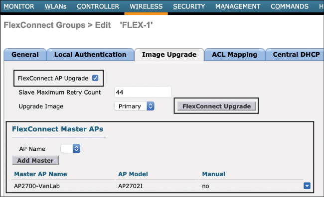
Figure 10-16 Configuration of the Smart AP Image Upgrade Feature in a FlexConnect Group
To summarize the example shown in Figure 10-16, the configuration is as follows:
The FlexConnect AP Upgrade option must first be selected.
Configure the slave maximum retry count. This is the number of times the slave will attempt to download the new image from the master. The default is 44, but this may be configured as desired.
Select the upgrade image—the options are Primary, Backup, and Abort.
From the AP Name option, select the AP that will be the master. In this example, one AP has been selected and all others in the FlexConnect group will be the slaves.
Once this configuration has been applied, click FlexConnect Upgrade to perform the upgrade.
Implementing FlexConnect with IOS-XE Controllers
As this is the first chapter that discusses implementation, a quick overview of the IOS-XE wireless controller configuration principles is warranted. Cisco introduced the family of IOS-XE controllers in 2018. IOS-XE controllers come in a variety of form factors, including the Catalyst 9800. Unlike AireOS controllers, which have been in use for many years, IOS-XE controllers inherit many of the native modular configuration capabilities of IOS-XE, while maintaining very similar features to the traditional AireOS. While the feature capabilities of AireOS and IOS-XE are very similar, the configuration methodology has significant differences.
In the AireOS controller, most wireless policies are centered around the WLANs, AP Groups, Flex Groups, and RF Profiles. In the IOS-XE controller, these configuration elements are decoupled (making them more reusable) and are modularized (making them more flexible), similar to other IOS- and IOS-XE-based systems.
IOS-XE controller policy and profile configuration is centered around three types of tags:
Policy Tags:
Define the broadcast domain (list of WLANs/SSIDs to be broadcasted) with the properties of the respective SSIDs
Equivalent to AP Group in AireOS
Site Tags:
Define the properties of the central/remote site
Define the Roaming domain for Flex APs
Equivalent to Flex Groups in AireOS but only for Flex APs (the maximum Flex mode APs per site tag is 100)
Used for local mode APs, recommended 400/500 APs per site
RF Tags:
Define the RF properties of the group of APs
Through the use of tags, IOS-XE controllers allow you to configure which policies will be adopted on which sites and what RF characteristics will be implemented, with the tags allowing policies and RF characteristics to be reused on other wireless segments.
Figure 10-17 illustrates a summary of these configuration aspects in the IOS-XE controller.

Figure 10-17 IOS-XE Controller Configuration Basics
The IOS-XE controller also supports configuration wizards that allow quick configuration of WLANs, APs, and sites.
To configure FlexConnect, navigate to the Configuration > Wireless Setup > Basic configuration page on the controller. This is illustrated in Figure 10-18.
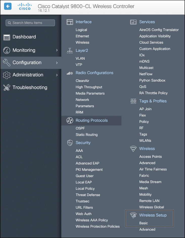
Figure 10-18 Wireless Basic Configuration
After navigating to the Configuration > Wireless Setup > Basic page, use the following steps to configure a new site for FlexConnect:
Step 1. Define the Location (such as a remote branch office location).
Step 2. Select Flex for Location Type (the options are Local or Flex).
Step 3. Select Client Density.
Step 4. Enter the Native VLAN ID.
Step 5. Add a AAA server (if not already added) and select it as the AAA for the remote location.
Figure 10-19 illustrates configuration of the new remote location under the Configuration > Wireless Setup > Basic > General tab.

Figure 10-19 Configure the Site for FlexConnect
Note the example in Figure 10-19 does not highlight the use tags because a configuration wizard is being used instead. The same configuration outcome can also be configured through the use of tags, but this is not shown for the sake of simplicity.
Once the site has been configured, navigate to the Wireless Network tab on the same page and follow these configuration steps (Figure 10-20 illustrates these configuration steps):
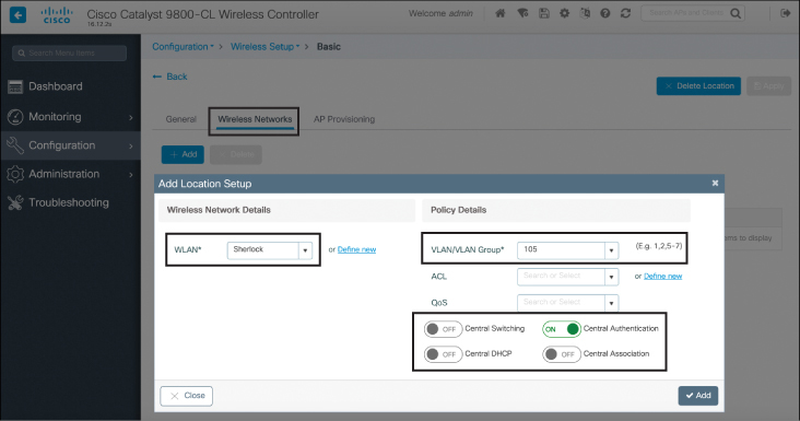
Figure 10-20 Configuring the FlexConnect Location Details
Step 1. Create the WLAN (or add it if already defined).
Step 2. Select a VLAN or a VLAN group—there will be a 1:1 mapping of VLANs to WLANs, and this needs to be configured for each locally switched WLAN used at the remote location.
Step 3. Select Authentication and switching methods.
Once the Wireless Networks components have been configured, the next step is to add the correct APs to the site. Navigate to the AP Provisioning tab and select the APs you wish to add and then click Apply. Figure 10-21 illustrates this step.
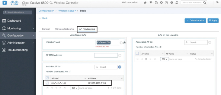
Figure 10-21 Adding the AP to the FlexConnect Group
The final step in the configuration is to add the locally switched VLANs to the Flex profile. Navigate to Configuration > Tags & Profiles > Flex. Under this tab, select the remote location you want to configure (which is really the Flex profile name). Figure 10-22 illustrates this configuration step.
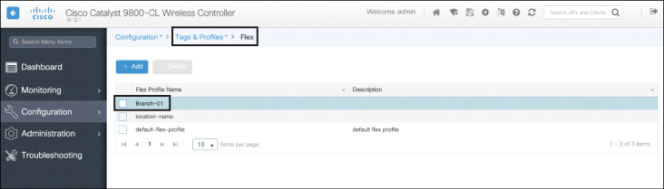
Figure 10-22 Adding the AP to the FlexConnect Group
From here, navigate to the VLAN tab and add the VLANs to the Flex profile. This is illustrated in Figure 10-23. Note each VLAN used.

Figure 10-23 Configuring the Locally Switched VLANs for the FlexConnect APs
With this last step completed, the location and Flex profile are configured and are ready for service. This example used the basic configuration wizard; however, behind the scenes the Policy, RF, and Site tags have all been configured in the CLI. Example 10-2 illustrates the CLI output from the configuration steps previously shown (note only the relevant configuration items are displayed).
Example 10-2 IOS-XE Controller CLI Configuration Output
catalyst9800#show run
aaa group server radius radgrp_Branch-01
 server name rad_192.168.10.1

wireless profile flex Branch-01
 acl-policy preauth_v4
 local-auth radius-server-group radgrp_Branch-01
 native-vlan-id 221
 vlan-name VLAN105
  vlan-id 105

wireless profile policy Branch-01_WLANID_5
 no central association
 no central dhcp
 no central switching
 description Branch-01_Sherlock

wireless tag site Branch-01
 ap-profile Branch-01
 flex-profile Branch-01
 no local-site

wireless tag policy Branch-01
 wlan Sherlock policy Branch-01_WLANID_5

wireless tag rf Branch-01
 24ghz-rf-policy Typical_Client_Density_rf_24gh
 5ghz-rf-policy Typical_Client_Density_rf_5gh

wlan Sherlock 5 Sherlock

ap location name Branch-01
 description "221b Baker Street"
 tag policy Branch-01
 tag rf Branch-01
 tag site Branch-01

ap profile Branch-01
Example 10-3 illustrates the output from the show wireless tag CLI command.
Example 10-3 A CLI Summary of the Wireless Tags Created Using the Configuration Wizard
catalyst9800#show wireless tag policy all

Policy Tag Name : Branch-01
Description     :

Number of WLAN-POLICY maps: 0
WLAN Profile Name                 Policy Name
------------------------------------------------------------------------
Sherlock                          Branch-01_WLANID_5

Number of RLAN-POLICY maps: 0


catalyst9800#show wireless tag rf all

Tag Name             : Branch-01
Description          :
----------------------------------------
5ghz RF Policy       : Typical_Client_Density_rf_5gh
2.4ghz RF Policy     : Typical_Client_Density_rf_24gh

catalyst9800#show wireless tag site all

Site Tag Name        : Branch-01
Description          :
----------------------------------------
Flex Profile         : Branch-01
AP Profile           : Branch-01
Local-site           : No
Image Download Profile: default
A Summary of FlexConnect Best Practices Recommendations
The following list summarizes recommended best practices when deploying FlexConnect for remote and branch wireless networks:
Enable unique FlexConnect groups for each remote location.
If the number of APs at the remote location exceeds 100 APs, either configure multiple Flex groups or deploy a local wireless controller at the remote location.
Ensure the wired switch VLANs match with the FlexConnect locally switched WLAN-to-VLAN mapping, including the native VLAN, which is used for CAPWAP traffic.
Configure features at the FlexConnect group level such as the VLAN-WLAN mappings.
Design the controllers for resiliency (either N+1 or SSO).
Enable CAPWAP Message aggregation to accelerate AP to controller communications (if using AireOS versions prior to 8.6).
Configure VLAN ACLs as necessary to implement security at the remote location.
Enable split tunneling (split ACL mapping) as necessary for centrally switched WLAN clients that need to access local resources.
Enable Smart AP image upgrade. Ideally, select and configure the master AP for image upgrades.
Office Extend
In some scenarios, no more than one access point is needed at a remote location. An example may be an employee’s home office or a very small remote office requiring just a single AP. Although FlexConnect may still be used in these scenarios, a simpler approach is to deploy Office Extend AP (OEAP). This type of deployment is designed to extend the corporate office network to a single AP over the Internet through a VPN connection, making the extended wireless network appear as if it is directly connected to the corporate network.
OEAPs provide secure communications from the access point at a remote location to the central controller, seamlessly extending the corporate WLAN over the Internet to a remote location, such as a home residence, thus providing the same experience for users at the home office as they would expect at the corporate office. Datagram Transport Layer Security (DTLS) encryption is used between the AP and the controller to ensure all communication is encrypted and protected.
Note
OEAP is only supported on specific access point models. Please consult the AP data sheet to determine which models support OEAP functionality.
Office Extend works in the following way. A user is given an AP that is primed with the IP address of the central controller. Alternatively, the user can enter the IP address of the controller from the web configuration screen. The user connects the AP into the home or office router. Once the AP boots and gets a local address, it communicates over the Internet to the address of the controller and creates a secured DTLS tunnel.
The OEAP then downloads its configuration and begins advertising the corporate SSID, thus making the user’s home or small office an extension of the corporate WLAN. Additionally, OEAPs have the ability to support local LAN ports, allowing the user to plug in a wired port that is also tunneled back to the controller. In addition, the user can enable an additional SSID for personal use, ensuring the corporate Wi-Fi network is not used for personal information.
To configure an AP as an OEAP, the AP first needs to be running in FlexConnect mode. From here, navigate to the wireless > All APs > (name) > FlexConnect page. Select the Enable Office Extend AP option. DTLS data encryption is enabled automatically when you enable the Office Extend mode for an access point.
Figure 10-24 illustrates how an AP may be converted to OEAP mode.

Figure 10-24 Converting a FlexConnect into an OEAP (AireOS Configuration Shown)
Once the AP has been converted to OEAP mode, the user can navigate to the OEAP’s web GUI at https://<ipaddressofAP>, where the personal SSID may be configured.
Summary
This chapter discussed the deployment of wireless in remote branch offices, focusing on FlexConnect. In this chapter you have learned the following:
Various options to deploy APs at remote branch offices, including the use of a local controller, Mobility Express, FlexConnect, and Office Extend
The operating modes of FlexConnect, including connected and standalone modes
The minimum latency and bandwidth requirements needed to deploy FlexConnect APs
Implementation steps required to deploy FlexConnect
The need to configure FlexConnect groups to allow seamless high-speed roaming at a branch location
How to configure FlexConnect for high availability
FlexConnect ACL VLAN mapping and split tunneling configuration
How to implement Smart AP Image Upgrade
Implementation of Office Extend APs
References
For additional information, refer to these resources:
AireOS FlexConnect Configuration Guide: https://www.cisco.com/c/en/us/td/docs/wireless/controller/8-8/config-guide/b_cg88/flexconnect.html
FlexConnect Feature Matrix: http://www.cisco.com/c/en/us/support/docs/wireless/5500-series-wireless-controllers/112042-technote-wlc-00.html
Catalyst 9800 FlexConnect Configuration Guide: https://www.cisco.com/c/en/us/td/docs/wireless/controller/9800/config-guide/b_wl_16_10_cg/flexconnect.html#ID340
Office Extend Configuration Guide, AireOS 8.8: https://www.cisco.com/c/en/us/td/docs/wireless/controller/8-8/config-guide/b_cg88/configuring_officeextend_access_points.html
AireOS Mobility Express Configuration Guide: https://www.cisco.com/c/en/us/support/wireless/mobility-express/products-installation-and-configuration-guides-list.html
Exam Preparation Tasks
As mentioned in the section “How to Use This Book” in the Introduction, you have a few choices for exam preparation: the exercises here, Chapter 18, “Final Preparation,” and the exam simulation questions in the Pearson Test Prep Software Online.
Review All Key Topics
Review the most important topics in this chapter, noted with the Key Topic icon in the outer margin of the page. Table 10-3 lists these key topics and the page numbers on which each is found.
Table 10-3 Key Topics for Chapter 10
Key Topic Element |
Description |
Page Number |
|---|---|---|
FlexConnect architectural example |
213 |
|
A summary of FlexConnect WAN requirements |
215 |
|
Configuration of a FlexConnect group |
221 |
|
IOS-XE wireless configuration basics |
232 |
|
List |
Summary of implementation recommendations |
236 |
Define Key Terms
Define the following key terms from this chapter and check your answers in the glossary: