
Chapter 17
Device Hardening
This chapter covers the following topics:
Implementing Device Access Controls: This section examines how remote network management through AAA systems, such as RADIUS and TACACS+, can be used to control management access to the controller and restrict certain functions on a per-user basis. This section also examines the steps involved in setting up device-level authorization using the Cisco Identity Services Engine (ISE).
Implementing Access Point Authentication: This section examines how to enable authentication on the AP using 802.1X and RADIUS so it can gain access to the network as a client.
Implementing CPU ACLs on the Wireless Controller: CPU ACLs are a method to limit access to services that involve the wireless controller’s CPU. This section discusses how this can be implemented as well as best practices to be aware of when using this feature.
This chapter covers the following ENWLSI exam topics:
8.1 Implement device access controls (including RADIUS and TACACS+)
8.2 Implement access point authentication (including 802.1X)
8.3 Implement CPU ACLs on the controller
Like other elements of a network, both physical and virtual wireless devices are susceptible to attack and need to be protected against potential vulnerabilities. One common strategy in protecting network devices is to reduce the attack surface as much as possible, thereby limiting the scope and domain of potential threats. One way to do this is to have central control of not only who can administer the controllers but what levels of access they are allowed to have. This type of granular and centrally controlled access is accomplished through AAA services using protocols such as RADIUS and TACACS+.
This chapter presents an examination of how RADIUS and TACACS+ are configured on the controller. In addition to implementation of security on the controller, this section reviews how AAA services can be implemented on ISE, allowing granular command-level administration for different user groups.
This chapter also examines how APs can be deployed in a campus where they themselves are authenticated as clients against LAN switches.
Finally, this chapter discusses how CPU ACLs can be used to harden wireless infrastructure devices. CPU access control lists (ACLs) are a method to protect the controller from attacks that could ultimately harm management functions on the controller, causing serious degradation of all wireless services. This feature does not come without risk, so the final section of this chapter discusses best practices to be aware of when deploying this capability.
“Do I Know This Already?” Quiz
The “Do I Know This Already?” quiz allows you to assess whether you should read this entire chapter thoroughly or jump to the “Exam Preparation Tasks” section. If you are in doubt about your answers to these questions or your own assessment of your knowledge of the topics, read the entire chapter. Table 17-1 lists the major headings in this chapter and their corresponding “Do I Know This Already?” quiz questions. You can find the answers in Appendix D, “Answers to the ‘Do I Know This Already?’ Quizzes and Review Questions.”
Table 17-1 “Do I Know This Already?” Section-to-Question Mapping
Foundation Topics Section |
Questions |
|---|---|
Implementing Device Access Controls |
1, 2 |
Implementing Access Point Authentication |
3, 4 |
Implementing CPU ACLs on the Wireless Controller |
5 |
1. Why would someone prefer to use TACACS+ over RADIUS for management of users on a wireless controller?
TACACS+ is considered more secure due to its encryption capabilities.
RADIUS support has been deprecated.
TACACS+ offers granular levels of command authorization.
TACACS+ would not be preferred. They are essentially the same except that RADIUS is an open standard allowing support by third-party AAA servers.
2. In ISE, what is the role of the Device Admin Policy Sets?
This is where the TACACS+ profiles are defined.
This is where the controller is given command-level authorization control from ISE.
This is where specific aspects of command-level access is defined.
This is where user groups are mapped to the TACACS+ profiles according to the policy rules.
3. What is the purpose of enabling an access point with an 802.1X supplicant?
This feature forces all user traffic to be authenticated against a back-end RADIUS or TACACS+ server, such as ISE.
This feature is used when the AP is not able to challenge the users for 802.1X credentials, so the switch performs this feature instead.
This feature enables authorization of which commands the controller is able to execute on the AP.
This feature is used in NAC deployments where the AP itself must be authenticated to gain access to the network.
4. What is required on ISE to implement 802.1X for access points?
Radius attributes specific for Cisco APs
Policy sets
Policy groups
TACACS+ with CoA
5. When deploying CPU ACLs, what is one consideration that should be addressed?
The final policy rule of the ACL should be an explicit “deny any” in most cases.
The final policy rule of the ACL should be an explicit “permit any” in most cases.
The CPU ACL must allow control plane functions originating from the controller itself, such as intercontroller, RRM, and DHCP communication.
The CPU ACL should also have Control Plane Policing enabled.
Foundation Topics
Implementing Device Access Controls
Controlling management access to a wireless LAN controller can be implemented either using local accounts directly on the controller or through an AAA server using RADIUS or TACACS+.
Using an AAA server for management-level access, whether it is for CLI or GUI access, has several operational and security advantages:
Centralized password and user management: If an administrator were to change a password, or if an administrator leaves the organization, centralized authentication means it is only necessary to make the change on the AAA server rather than on each device individually. Consider an organization that may have tens or even hundreds of wireless LAN controllers distributed around the world. If the local usernames and passwords were maintained on each device, modifying a user account would require significant effort whenever a change is required.
Centralized permission and command-level authorization to devices: Using an AAA server, granular permission rules and policy can be implemented in one central place rather than in many. Using TACACS+, the AAA server can also provide granular levels of access to functions of the controller for different administrators or groups. For example, the AAA server may have a policy rule that grants certain users read-only access, while other administrators may have full access to all configuration options.
Accounting: AAA servers support centralized accounting services, allowing each command that is executed on the wireless controller to be recorded for later review. This may be used as forensic evidence if the device is incorrectly configured or is maliciously tampered with.
Device Control: A particular device can be centrally deauthorized or deactivated from the network if an administrator wishes to remove it. This may be useful if a device has gone missing or if it is older and needs to be deprecated.
Note
RADIUS servers only offer two types of authorization to the controller: read-write or read-only access. TACACS+ supports more granular command-level authorization of the configuration, both through the CLI and the web interface.
AAA Design Overview
When an administrator logs in to the controller, the controller can provide authentication services based on local credentials (stored directly on the controller) or it can authenticate using a remote AAA server that is accessible by the controller. Cisco wireless LAN controllers support both RADIUS and TACACS+ authentication methods.
The AAA authentication process works as follows:
A management user logs in to the controller (either through the management GUI or through SSH). The controller responds, asking for the user to provide credentials (the username and password).
Once the user provides login credentials to the controller, the controller sends these to the RADIUS or TACACS+ AAA server (such as ISE) and asks the user to be authenticated and authorized. The AAA server first authenticates the user (based on supplying the correct username and password) and then provides an authorization level for this user, such as read-only or read-write privilege, or in the case of TACACS+, which functions of the controller the user is allowed to access.
The user is then granted or declined access based on the response from the AAA server. If the user is granted access, the user is only allowed to access specific aspects of the controller configuration that have been authorized by the AAA server.
Figure 17-1 illustrates this process.

Figure 17-1 Using a Remote AAA Server to Authenticate a Management User on the Wireless Controller
AAA Configuration Overview on the Wireless Controller
This section examines how to implement centralized RADIUS authentication for administrators of a wireless LAN controller.
In an AireOS controller, navigate to Security > AAA > RADIUS > Authentication to configure the AAA server. In this configuration page, select the Management radio button to enable the RADIUS server function to authenticate administrators who log in to the WLC (without this enabled, the RADIUS server can only be used for wireless client authentication). Once this option is enabled, the AAA server will be used as a RADIUS authentication server for administrators, and all controller user-management authentication requests will go to the RADIUS server. This will be used for administrators who attempt to log in to either the web interface or the command line via SSH.
Figure 17-2 illustrates this configuration page.
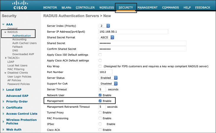
Figure 17-2 Configuring an AireOS Controller for RADIUS Management Authentication
Note
Modern RADIUS servers use UDP 1812 for authentication and authorization and UDP 1813 for accounting. However, in legacy RADIUS versions these ports were different: UDP 1645 was used for authentication and authorization and UDP 1646 was used for accounting.
Configuration of TACACS+ is done through the Security > AAA > TACACS+ > Authentication menu. Configuration is similar to RADIUS, with the exception that it is not necessary to explicitly select the management option.
On the Catalyst 9800, configuration of AAA for management users is accomplished by navigating to Configuration > AAA in the web interface. From here, there are two options: directly configure the RADIUS/TACACS+ servers manually or launch the AAA Wizard option. Figure 17-3 illustrates what is seen after launching the AAA Wizard.
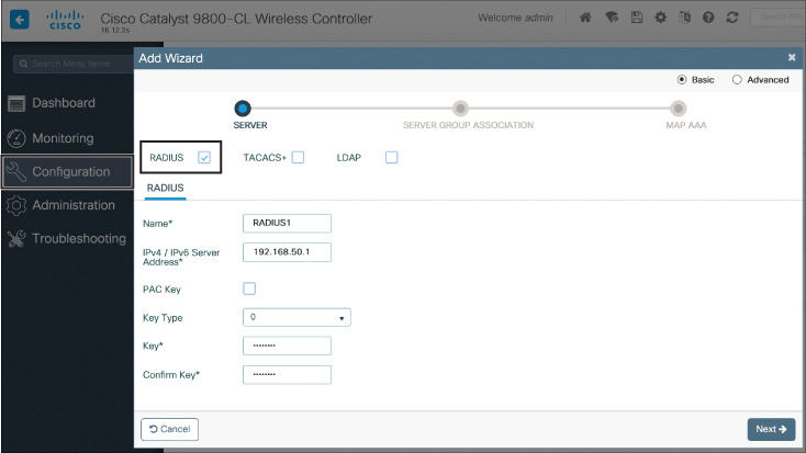
Figure 17-3 Configuring a RADIUS Server Through the AAA Wizard
Once the RADIUS server has been defined, click Next. To enable administrative management authentication services, select the login pull-down option on the Server Group Association screen, as shown in Figure 17-4.

Figure 17-4 Configuring the Controller to Use a RADIUS Server for Management (Login) Authentication
The last step is to assign the RADIUS or TACACS+ server to the Assigned Server Group. The purpose of this step is to allow different AAA servers to be used for wireless client 802.1X authentication versus management authentication services (only enable this if a separate AAA server is used for management authentication purposes; if not, just use the same AAA server).
Implementing TACACS+ Profiles and Command Authorization
Terminal Access Controller Access Control System Plus (TACACS+) is a client/server protocol that provides centralized security for users attempting to gain management access to a networking device. It serves as a centralized authentication system similar to RADIUS; however, one key difference is that RADIUS provides only authentication support with limited authorization (users can only be authorized as read-only or read-write), whereas TACACS+ provides authentication, granular authorization, and accounting services. TACACS+ also uses TCP port 49, making it a reliable protocol for communications (RADIUS uses UDP).
For TACACS+, authorization is based on a privilege level (or role) that grants the administrator access to different configuration aspects of the controller. For AireOS controllers, the available roles correspond to the seven configuration menu options on the controller’s web interface: MONITOR, WLAN, CONTROLLER, WIRELESS, SECURITY, MANAGEMENT, and COMMANDS. An additional role, LOBBY, is available for administrators who require only lobby ambassador privileges. The roles to which users are assigned are configurable in the AAA TACACS+ server (that is, ISE). Users can be authorized for one or more roles, giving far more flexibility than a RADIUS server’s read-only or read-write options.
The minimum TACACS+ authorization level is MONITOR only, which is equivalent to read-only access in RADIUS. The maximum level is ALL, which authorizes an administrator with super-user privileges to execute configuration changes across the entire controller (both at the CLI and web interface). For example, a user who is assigned the role of SECURITY can make changes to any items appearing on the Security menu (or security commands in the CLI) but will be restricted from the other configuration options. If users are not authorized for a particular role (such as WLAN), they can still access that menu option in read-only mode (or the associated CLI show commands), but they will not be able to make any configuration changes. If the TACACS+ server becomes unreachable or unable to authorize, users will be unable to log in to the controller, so it is generally wise to have a fallback server available.
If users attempt to make changes on the controller that they are not authorized for according to their assigned role, a message on the GUI will appear indicating that they do not have sufficient privileges.
In order for a controller to support TACACS+ authorization, this feature must be enabled on both the controller and the AAA server. In AireOS controllers, this is configured in the Security > Authentication > TACACS+ > Authorization menu and is straightforward to configure (this follows the same web interface configuration shown in Figure 17-3).
To configure TACACS+ role-based access controls in ISE, the wireless controller must first be added as a network device. This is done by navigating to the Administration > Network Resources > Network Devices menu in ISE. Once the device credentials for the wireless LAN controller have been added, it will appear as shown in Figure 17-5.

Figure 17-5 Adding the Wireless LAN Controller as a Network Device in ISE (Note: ISE Version 2.6 Used Here)
Once the network device has been added, the next step is to ensure that the ISE server is itself enabled to authorize administrative control for network devices. This is done by navigating to Administration > System > Deployment and clicking the name of the ISE server (shown as “iceman” in the example in Figure 17-6).

Figure 17-6 Navigating to the ISE Deployment Settings
From this screen, ensure that Enable Device Admin Service is correctly checked, as shown in Figure 17-7.
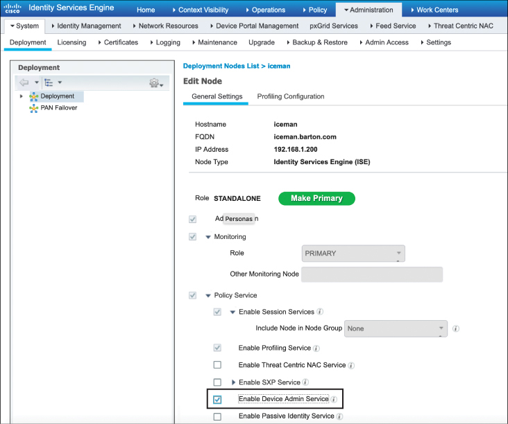
Figure 17-7 Enabling the ISE Server Admin Service
The next step is to define the TACACS+ profiles that will be used to grant specific levels of access to different groups of administrators.
Note
An assumption is made that an LDAP directory service such as Active Directory has been configured on the ISE server and will return group identifiers that can be used for TACACS authorization. If an LDAP server is not in use, it is also possible to use locally defined users in ISE.
Navigate to the Work Centers > Device Administration > Policy Elements menu in ISE and expand the Results tab on the left. Clicking TACACS Profiles causes certain default profiles to be displayed. Figure 17-8 illustrates this step.
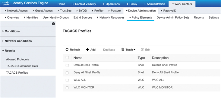
Figure 17-8 Navigating to the TACACS Profiles in the Policy Elements Page of ISE
TACACS Profiles allow granular privileges to be created, giving different administrators access to selected portions of the controller’s web interface and CLI. For example, clicking the +Add button causes a screen similar to Figure 17-9 to be displayed.
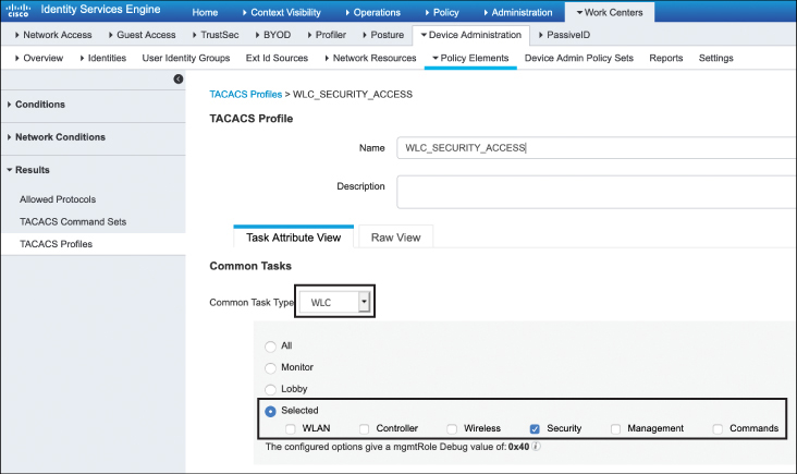
Figure 17-9 Configuring a Policy to Only Allow Access to the Security Configuration Area of the Controller
Figure 17-9 shows the various command-level authorization profiles available. Here, the Security option is selected. This specifically relates to the AireOS class of controllers. If the Catalyst 9800 is in use, the Shell option can be selected, which equates to the 0–15 privilege levels commonly used in IOS and IOS-XE.
This example demonstrates the creation of a TACACS profile that will grant an administrator access to only the Security tab of the controller. As such, the name of the profile in Figure 17-9 is called WLC_SECURITY_ACCESS, and only Security is selected in the profile option table.
As different profiles are created, any combination of the options shown in Figure 17-9 may be selected, and as many different profiles as are required may be defined (although it is reasonable to keep the number of profiles small for administrative simplicity).
Once the TACACS profiles have been configured, the last step is to create a policy that maps user groups to these policies. To do this, navigate to the Work Centers > Device Administration > Device Admin Policy Sets menu in ISE, as shown in Figure 17-10.
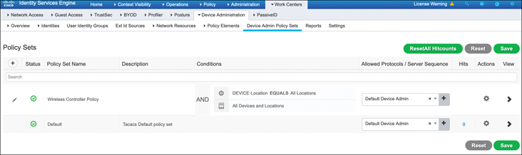
Figure 17-10 Navigating to the Device Admin Policy Sets Page Where the TACACS Profile Will Be Applied to User Groups
As shown in Figure 17-10, a new policy has been created called Wireless Controller Policy. Although the device admin policy can be extremely granular if needed, in this case the policy is wide open and will be triggered when the device location matches All Locations, meaning all network devices defined in ISE will use this rule.
By clicking the arrow at the far right of the policy, it is possible to configure the authorization policy where specific user groups are mapped and actions can be taken. Figure 17-11 shows four entries for this policy. The Authorization Policy rules first match against a condition. Note that there are names assigned to these conditions. These are simply rules that identify which user groups will match the policy (for example, the condition may match which Active Directory group they are part of). For each rule, the result will be an assignment to one of the previously defined profiles, shown in this example as WLC MONITOR, WLC_SECURITY_ACCESS, WLC ALL, followed by an implicit deny all profiles at the end of the rule set (meaning if they don’t fall into one of the prior groups, the user is declined access).
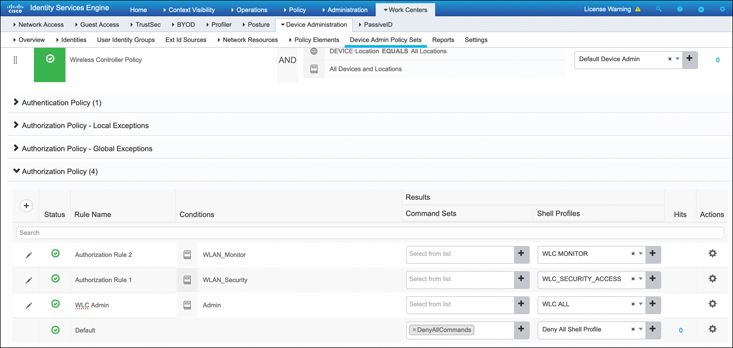
Figure 17-11 Configuring the ISE Authorization Policy
Implementing Access Point Authentication
When networks are widely deployed with Network Admission Control (NAC), client devices must support some method of authentication to gain access to the network. Most commonly, 802.1X supplicants are used on client devices so they can be authenticated through a local switch and the backend AAA server (that is, ISE). While support for 802.1X supplicants in most computers and mobile devices is expected, other network devices such as IP phones, printers, IoT devices, and wireless APs may require specific configuration if network-wide 802.1X is implemented.
In this regard, this section explores how to implement an 802.1X supplicant on a Cisco AP. Once a switch port is configured as an 802.1X authenticator, the switch will restrict the AP’s traffic until it authenticates successfully with 802.1X. Thus, only after the AP is configured to act as an 802.1X supplicant will it be authenticated and given access to the network.
On Cisco controllers, EAP-FAST is used with anonymous Protected Access Credentials (PAC) provisioning to enable 802.1X authentication of access points.
Implementation of 802.1X on the access point requires the three following steps:
Enable the 802.1X supplicant on the AP (either globally or on a per-AP basis).
Configure the local switch port with 802.1X and the backend ISE server as the authentication server.
Configure ISE with the correct security policies to authenticate and authorize traffic from the AP.
Figure 17-12 illustrates how the 802.1X supplicant may be configured on an AP. In an AireOS controller, this is configured in the Wireless > Access Points menu. Note that the 802.1X supplicant configuration may be implemented either locally on a per-AP basis or globally for all APs. In this configuration step, the 802.1X credentials must be entered and the EAP-FAST method must be selected. In the example shown here, the AP username maverick is used.
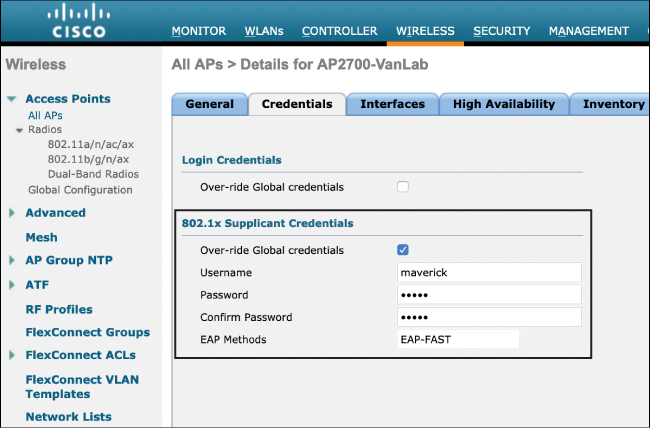
Figure 17-12 Configuring the AP with 802.1X Supplicant Credentials
Once the APs have been configured with 802.1X supplicants, the local switch must be configured to authenticate devices with 802.1X on a per-interface basis and the AAA server must be defined in the global configuration of the switch.
Example 17-1 illustrates a sample configuration on a Cisco Catalyst switch.
Example 17-1 Configuring the Switch for 802.1X Authentication
! enable dot1x on the switch globally and add the ISE server to the switch

aaa new-model
!
aaa authentication dot1x default group radius
!
dot1x system-auth-control
!
radius server ISE
address ipv4 10.48.39.161 auth-port 1645 acct-port 1646
 key 7 123A0C0411045D5679

! next configure AP switch port for dot1x
interface GigabitEthernet0/15
 switchport access vlan 123
 switchport mode access
 authentication order dot1x
 authentication port-control auto
 dot1x pae authenticator
 spanning-tree portfast edge
In the final step, ISE must be configured to authenticate the AP and authorize it for access to the network. After logging in to ISE, the first step is to ensure that EAP-FAST is allowed in the Allowed Protocols for default network access.
Figure 17-13 shows how this is configured under the Policy > Policy Elements > Results > Default Network Access tab.

Figure 17-13 Enable EAP-FAST in the Allowed Protocols
Similar to users who are authenticating to gain network access, the device’s username and password credentials must also be added to ISE; however, in this case there must be a special group defined for these types of users (this will be used later when authorizing the AP for access to the network).
Figure 17-14 illustrates the creation of a new user group called APs and adding the user credentials for maverick to this group (the username of the AP that is to be authenticated). This is added in the Administration > Identity Management > Groups > User Identity Groups menu. Note that the AP’s user identity can be stored either locally or in a remote directory store such as Active Directory.

Figure 17-14 Configure the AP Authentication Credentials
Once the user is defined, the final step is to create the authentication and authorization policies for the AP. ISE uses the concept of policy sets to apply customized policy rules to different kinds of users or devices. Policy sets are really just an ordered list of rules that first match a set of authentication criteria and then apply different policies based on the outcome of the rule.
Once a new policy set has been created and named, the next step is to identify the conditions that will trigger the policy set. This simply means that if there is an event that matches these conditions, the subsequent authentication and authorization policy rules will be invoked. For example, Figure 17-15 illustrates a new policy called dot1x Policy Set. In order to invoke the authentication or authorization policies, an authentication method of either Wired_802.1X or Wireless_802.1X must have been used. Obviously, this covers a pretty wide array of authentication possibilities, but it is used here to illustrate the purpose of a policy set (meaning the rule will be used for either wired or wireless 802.1X access attempts). Note also a default policy set is defined if none of the earlier ones are matched.
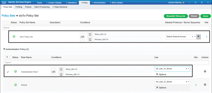
Figure 17-15 Configure the ISE Policy Set and Authentication Rule
Once the policy set has been set up, it is now possible to configure the authentication and authorization policies below it. Clicking the right-pointing arrow on the policy set causes the suboptions menu to open, which includes the authentication and authorization submenus. As shown in Figure 17-15, an authentication rule can be configured. In this case, a simple rule is implemented that matches on either the Wired or Wireless 802.1X authentication method, and All_User_ID_Stores is used to authenticate the user. Note that the default rule would have also worked in this case, as it will attempt to authenticate users against all known ID stores (it could also be more granular if desired).
The final step is to configure the authorization policy. This is a key configuration step, as it allows the AP and all traffic it passes to have access to the network. In this case, a new rule is created called Port_AuthZ. The conditions of the rule are that the user must be part of the Identity Group name APs and that the user must be authenticating through the Wired_802.X method. The result of a successful match is that the AP is permitted access to the network. Note in Figure 17-16 how this authorization rule has been created and how the default rule below it is an explicit deny if authentication fails.
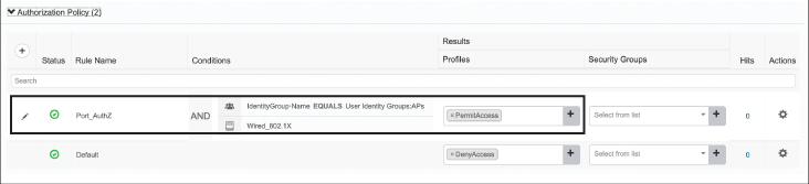
Figure 17-16 Configure the ISE Authorization Rule to Allow Network Access
Implementing CPU ACLs on the Wireless Controller
Another method to harden and protect the wireless controller is to implement CPU access control lists (ACLs). CPU ACLs are used to restrict what kind of traffic is allowed and which devices can communicate with the controller’s control plane functions governed by the CPU. This includes SSH, ICMP, and other management functions that are processed by the CPU.
It is important to mention a few key characteristics of CPU ACLs:
For AireOS controllers using versions 6.0 and later, CPU ACLs are applicable for traffic originating both to and from the controller. Thus, when you’re creating the ACLs and attaching them to the CPU, the ACL direction fields do not have any relevance.
By default, CPU ACLs use an implicit deny rule at the end of the ACL, meaning once the ACL is implemented, critical management and control functions may be restricted if they are not explicitly permitted. Since this can cause unexpected problems, if CPU ACLs are used, it is generally recommended to use an explicit permit all statement at the end of the ACL.
The controller has a set of filtering rules for internal processes that can be checked with the sh rules command. ACLs do not affect these rules, nor can these rules be modified on the fly. However, CPU ACLs take precedence over these internal rules.
One of the main challenges to be considered when deploying a strict CPU ACL is the possible impact it may have on critical management and control functions that are not explicitly permitted by the ACL. For example, the implicit “deny any” statement at the end of the ACL policy may impact communications between controllers on the same mobility group, DHCP functions, and many critical activities of the controller. Thus, it is highly recommended to limit the rules of the CPU ACL to only what must be absolutely restricted and permit everything else. In fact, if CPU ACLs are incorrectly implemented on the controller, the administrator could be locked out of the controller with no way back in other than through physical access to the console.
In many situations, CPU ACLs can be risky, so the general guideline is to only use them to restrict remote access methods, such as SSH, Telnet, HTTP, HTTPS, and ICMP from specific risky locations, and then use a “permit any” statement at the end. Note that it is also possible to implement these kinds of rules on a firewall or aggregation router in front of the controller, so a controller CPU ACL may not be necessary.
Figure 17-17 illustrates the creation of sample CPU ACL on an AireOS controller that restricts HTTP and ICMP traffic from various parts of the network. Note the “permit any” rule at the end of the policy.
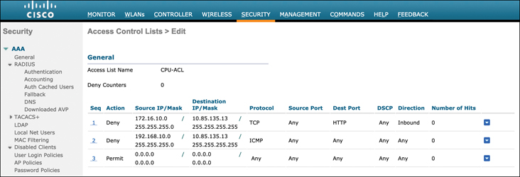
Figure 17-17 Configuring a CPU Access Control List
Once the ACL has been defined, the final step is to attach it to the CPU ACL policy. This can be configured in the Security > Access Control Lists > CPU ACLs menu. Figure 17-18 illustrates this configuration step.
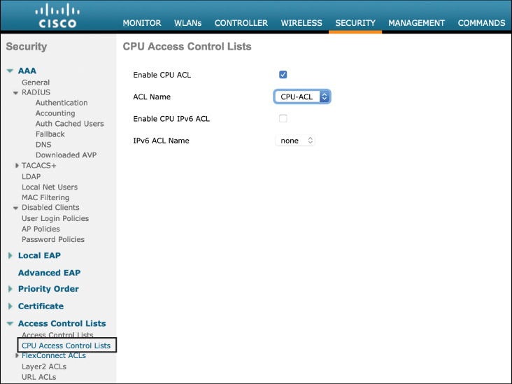
Figure 17-18 Implementing the CPU Access Control List
Note
One aspect of protecting a network device is to make sure that the control plane and CPU are not overwhelmed with more management traffic than they can process. This is commonly referred to as control plane policing. On all Cisco controllers (after AireOS 4.1), control plane policing is enabled by default. This function is enabled if control plane traffic directed toward the CPU exceeds 2Mbps. It is possible to enable or disable this feature but not to set trigger data rates against which traffic it will act. In normal operations, it is recommended this feature be left enabled.
Summary
This chapter focused on methods of hardening devices in the wireless LAN deployments. In this chapter you have learned the following:
How to set up the wireless controller to be managed through AAA services such as RADIUS and TACACS+
How ISE can be used to control privilege levels of management access to the wireless controller
How to configure the AP as an 802.1X supplicant such that it can gain network access to a secured switch
How to configure the ISE policy to authenticate and authorize an AP onto the network
How to implement CPU ACLs on the controller and when this should be done
References
For additional information, refer to these resources:
How to implement access to the wireless controller management with RADIUS and TACACS+: https://www.cisco.com/c/en/us/td/docs/wireless/controller/8-5/config-guide/b_cg85/aaa_administration.html
Configuring the AP as an 802.1X supplicant: https://www.cisco.com/c/en/us/support/docs/wireless-mobility/wireless-fixed/107946-LAP-802-1x.html
Implementing CPU ACLs on the controller: https://www.cisco.com/c/en/us/td/docs/wireless/controller/8-5/config-guide/b_cg85/access_control_lists.html
Configuring an external RADIUS server in the Identity Services Engine (ISE): https://www.cisco.com/c/en/us/support/security/identity-services-engine/products-installation-and-configuration-guides-list.html
ISE and Catalyst 9800 Integration Guide: https://community.cisco.com/t5/security-documents/ise-and-catalyst-9800-series-integration-guide/ta-p/3753060#toc-hId--389699194
Exam Preparation Tasks
As mentioned in the section “How to Use This Book” in the Introduction, you have a few choices for exam preparation: the exercises here, Chapter 18, “Final Preparation,” and the exam simulation questions in the Pearson Test Prep Software Online.
Review All Key Topics
Review the most important topics in this chapter, noted with the Key Topic icon in the outer margin of the page. Table 17-2 lists these key topics and the page numbers on which each is found.
Table 17-2 Key Topics for Chapter 17
Key Topic Element |
Description |
Page Number |
|---|---|---|
Using a remote AAA server to authenticate a management user on the wireless controller |
443 |
|
Configuring an AireOS controller for RADIUS management authentication |
444 |
|
Configuring the ISE authorization policy |
450 |
|
Configuring the switch for 802.1X authentication |
451 |
|
Configuring the ISE policy set and authentication rule |
453 |
|
Configuring a CPU access control list |
455 |
Define Key Terms
Define the following key terms from this chapter and check your answers in the glossary:
Remote Authentication Dial-In User Service (RADIUS)
Terminal Access Controller Access-Control System+ (TACACS+)