
Chapter 15
Security for Wireless Client Connectivity
This chapter discusses the following topics:
Implementing 802.1X and AAA on Wireless Architectures: This section examines how EAP and 802.1X work in a wireless LAN, exploring the various network components involved in end-to-end client security. This section also looks at how ISE is implemented in wireless networks to provide authentication and authorization services.
Implementing Client Profiling: This section examines the wireless client onboarding process and how clients can be profiled based on their authentication credentials, the type of device that is associating, and many other criteria. This section examines how client profiling and policy can be implemented both on the controller and in ISE.
Implementing BYOD and Guest: BYOD and wireless guest access (through portals) are widely used wireless deployments. This section looks at various ways to deploy guest networks with the Cisco wireless controller and ISE. In addition, this section examines how to deploy Bring Your Own Device (BYOD), including how and where authentication of the users should take place, including the differences between local and central web authentication methods.
This chapter covers the following ENWLSI exam topics:
6.1 Configure client profiling on WLC and ISE
6.2 Implement BYOD and guest
6.2.a CWA using ISE (including self-registration portal)
6.2.b LWA using ISE or WLC
6.2.c Native supplicant provisioning using ISE
6.2.d Certificate provisioning on the controller
6.3 Implement 802.1X and AAA on different wireless architectures and ISE
6.4 Implement Identity-Based Networking on different wireless architectures (VLANs, QoS, ACLs)
As you begin to deploy a wireless network, no doubt security is top of mind. However, deploying security can be one of the most complex challenges to implement and manage. In addition, over the last 20 years, the IEEE has been continually improving security standards, introducing new frameworks such as Wireless Protected Access version 3 (WPA3). However, best practices for wireless security go far beyond the jurisdiction of WPA. For example, just because a client is able to provide authentication credentials doesn’t mean all devices with these credentials should be given the same level of access to a network or to all places in a network. To illustrate, a wireless client that is brought from home and is essentially untrusted should not be given the same level of access to sensitive parts of the network as a fully trusted device. In addition, based on the type of device, different levels of QoS may be warranted, such as devices that require high-definition video. Furthermore, depending on the type of device and the user who authenticates, it may be desirable to associate different security profiles to certain user groups or even assign them to specific VLANs.
Allowing guests to use the wireless network through the use of a portal is another aspect that has become increasingly important in recent years. While an organization may grant access to guest users, ensuring they do not become a security risk and have access to sensitive areas of the network is an important requirement that must be considered. This involves not only how the guest portal is made available to end users but also how the wireless network itself is architected.
BYOD is yet another area that can be challenging to secure. BYOD is becoming commonplace in many corporations where users are encouraged to bring their own mobile devices from home and use them on the corporate network. Not only are these BYOD devices untrusted and in some cases insecure, there is no way to know what software (or malware) may be lurking on such devices. To facilitate the use of BYOD, it has become necessary to provide users a secure way to self-register their devices and then deploy security software to the BYOD devices so that they can be trusted on the corporate network. Over the last several years, Cisco has developed BYOD capabilities on the controller and ISE that facilitate this.
“Do I Know This Already?” Quiz
The “Do I Know This Already?” quiz allows you to assess whether you should read this entire chapter thoroughly or jump to the “Exam Preparation Tasks” section. If you are in doubt about your answers to these questions or your own assessment of your knowledge of the topics, read the entire chapter. Table 15-1 lists the major headings in this chapter and their corresponding “Do I Know This Already?” quiz questions. You can find the answers in Appendix D, “Answers to the ‘Do I Know This Already?’ Quizzes and Review Questions.”
Table 15-1 “Do I Know This Already?” Section-to-Question Mapping
Foundation Topics Section |
Questions |
|---|---|
Implementing 802.1X and AAA on Wireless Architectures |
1–3 |
Implementing Client Profiling |
4, 5 |
Implementing BYOD and Guest |
6–8 |
1. Which of the following protocols is used between a client and the authentication server?
LDAP
802.1X
EAP
2. Which of the following EAP methods supports X.509 certificates on client and server?
EAP-FAST
EAP-TLS
EAP-GTC
PEAP
EAP-MSCHAPv2
3. Which EAP method supports fast roaming?
PEAP
EAP-MSCHAPv2
EAP-FAST
EAP-GTC
4. Which of the following local profiling options is not used on the controller?
MAC OUI
Device Type
DHCP
HTTP
NMAP
5. After a client has been profiled, what policy features may be used? (Choose all that apply.)
VLAN ID assignment
Time of day restrictions
QoS profile
ACLs
6. What is a key property of LWA? (Choose two.)
In LWA, the guest/BYOD portal may only be implemented on the controller.
In LWA, the guest/BYOD portal may be implemented on either the controller or another server such as ISE.
In LWA, the redirect URL and ACLs are configured on ISE.
In LWA, the redirect URL and ACLs are configured on the controller.
7. What is are key differences between CWA and LWA? (Choose two.)
LWA uses Layer 2 only, whereas CWA uses Layer 3 only.
LWA uses Layer 3, whereas CWA uses a mixture of Layer 2 and Layer 3.
LWA uses MAC filtering, whereas CWA does not.
CWA uses MAC filtering, whereas LWA does not.
8. After authentication with CWA, how does ISE make security changes to the client on the controller?
RADIUS attributes
SNMPv3
CoA
TACACS+
Foundation Topics
Implementing 802.1X and AAA on Wireless Architectures
Before a wireless client device can communicate, it must first authenticate to the access point and controller using a trusted authentication mechanism that verifies the client’s identity and credentials. Using security best practices, once a client has been authenticated, it is provided an encryption key to ensure confidentiality of the data communication. In this section, the security architecture of the wireless network will be discussed, along with the various network elements and methods involved in client authentication. This will include an overview of how the various Extensible Authentication Protocol (EAP) methods work and how they are implemented in Cisco wireless networks.
Wireless Network Authentication Framework
To ensure wireless security, clients must be first authenticated and then use encryption in their communication. Although pre-shared keys are simple to deploy and require minimal authentication infrastructure (you will often see pre-shared keys used in home wireless networks), it is recommended to deploy a more robust and manageable system in corporate wireless networks. For example, if a large network was deployed with pre-shared keys, it would be a trivial matter for any client to decrypt and record any other client’s traffic with the same pre-shared key. If one of the clients became compromised, things would be much worse. This would then require the immediate manual rekeying of all devices everywhere—something that is next to impossible to accomplish. In addition, with pre-shared keys, it is not possible to see the unique identity of the users who are associated to the wireless network.
A much better alternative is to use a mechanism based on the EAP authentication framework. EAP is an authentication framework for the communication of identity credentials over a network, either wired or wireless. EAP employs IEEE 802.1X between the client and the wireless controller, as well as RADIUS between the controller and the back-end authentication server. Today, both the IEEE 802.11i standard and the Wi-Fi Alliance Wireless Protected Access (WPA) compatibility standard have adopted 802.1X for authentication on wireless LANs.
Note
Defined in RFC 3748 (now updated in RFC 5247), EAP is not actually a single security protocol but is rather a framework that provides common security functions and methods to handle authentication credentials over a network. Currently, approximately 40 different EAP authentication methods exist, but only a few are in common use.
Today, EAP is widely deployed in corporate wireless networks worldwide. EAP allows clients to be authenticated before they are fully associated to the wireless network, and it allows the wireless infrastructure to authorize them for different levels of security, access, and QoS once they have been authenticated. Figure 15-1 illustrates the overall EAP authentication framework and associated components.

Figure 15-1 The Wireless Network Authentication Framework
As illustrated in Figure 15-1, the authentication framework leverages EAP, end to end. Between the client and the AP/controller EAP runs over 802.1X, and between the AP/controller and the Authentication server it runs over RADIUS. The framework includes the following key components:
Supplicant: The supplicant is a piece software that runs on the client device. The supplicant is responsible for providing the identity (the username) and password of the client to the authenticator over EAP. The supplicant is commonly a native part of the mobile device’s operating system, or it may be installed separately, such as the Cisco AnyConnect Secure Mobility Client.
Authenticator: The authenticator is the network device that authenticates the client device (such as the AP and/or the controller). In a wired LAN this would be the switch directly connected to the wired client. In a wireless LAN, this is either the access point or the controller, depending on how the APs are deployed. The authenticator is also referred to as a Network Access Device (NAD).
Authentication server (AS): This is the back-end RADIUS component that authenticates the client device via the authenticator. Cisco ISE is an example of an authentication server that is able to apply network policy controls to clients as they connect to the network. The AS is also commonly referred to as the Network Authentication Server (NAS).
Identity store: The identity store is a directory server that is typically accessed by the authentication server using Lightweight Directory Access Protocol (LDAP). The authentication server may also have an identity store, although this is less common. The identity store may also optionally include a certificate authority. Active Directory is a common example of an identity store.
Extensible Authentication Protocol (EAP)
Authentication begins at the time of association when the supplicant on the wireless client provides its user credentials to the authenticator, which then passes them to the authentication server.
End to end, EAP encapsulates usernames, passwords, certificates, tokens, and other credentials that allow the client to be authenticated. As shown in Figure 15-1, EAP communication is established between the supplicant and the authentication server. However, there are two steps to establish this communication. First, 802.1X using EAP over LAN (EAPoL) is used between the supplicant and the authenticator. Second, RADIUS is used between the authenticator and the authentication server.
Authentication occurs in the following steps:
EAPoL Start: The supplicant initiates an authentication request to the AP/controller.
EAPoL Request Identity: The authenticator requests the supplicant to supply credentials to access the network.
EAP Identity Response: The supplicant supplies its identity to the authenticator. The authenticator (the AP/wireless controller) forwards the identity to the authentication server (ISE).
EAP Request-EAP Type: The authentication server responds with an EAP type (an EAP method) that it requests the supplicant to use. This is returned to the authenticator using RADIUS AV pairs.
EAP Response-EAP Type: The supplicant returns confirmation of the EAP method that it will use to communicate with the authentication server.
EAP Success: The authentication server responds with an EAP Success message that communication has been established and the client may now be authenticated.
This process is illustrated in Figure 15-2.

Figure 15-2 The EAP Authentication Process
Figure 15-2 illustrates the overall EAP authentication process; however, this is somewhat generic. In reality, many different implementations of EAP exist (known as EAP methods). The EAP method depends on the software and configuration of the supplicant, as well as which methods are supported by the network. While the overall frameworks of the various EAP methods are similar, implementations of EAP offer different security characteristics that may be required by an organization, such as the use of a public key infrastructure (PKI) and certificates on a supplicant rather than relying on only username and passwords.
Common EAP types generally fall into one of three classes: inner methods, tunnel methods, and certificate-based methods. These are described as follows:
Inner methods: Inner methods involve the direct authentication of the user credentials between a supplicant and an authentication server. Common EAP inner methods include the following:
EAP-MSCHAPv2: Microsoft Challenge-Handshake Authentication Protocol version 2 is one of the most popular inner methods in use today. MSCHAPv2 allows for simple transmission of username and password from a supplicant to the RADIUS server.
EAP-GTC: EAP Generic Token Card is a method that was created by Cisco as an alternative to MSCHAPv2. It allows integration with a wide variety of identity stores, including one-time password (OTP) token servers, LDAP, and others.
EAP-TLS: EAP Transport Layer Security (TLS) is an X.509 certificate-based mechanism that employs both client-side and server-side certificates and requires a PKI.
Tunnel methods: Tunnel methods are typically employed in conjunction with an inner-EAP method, such as EAP-MSCHAPv2. Due to their weaker security, inner methods are often encrypted inside an EAP tunnel to give them an added level of protection (effectively, two tiers of protection). With tunneled EAP methods, authentication occurs in a nested fashion. First, the outer authentication (outside the TLS tunnel) is established, and then inner authentication occurs (inside the TLS tunnel).
Common EAP tunnel methods include the following:
PEAP (Protected EAP): Jointly developed by Cisco, Microsoft, and RSA, PEAP is a tunneled method that requires a certificate on the server but not on the client. PEAP forms an encrypted TLS tunnel between the client and server similar to how an SSL tunnel is used between a browser and a secure website. Once the PEAP tunnel is established, an inner method such as EAP-MSCHAPv2 is used to authenticate the client.
EAP-FAST (Flexible Authentication via Secure Tunnels): EAP-FAST was developed by Cisco and is similar to PEAP in the way it uses a secure TLS tunnel between client and server (however, the server-side certificate is optional with EAP-FAST). The main advantage of EAP-FAST is in how it provisions Protected Access Credentials (PACs) on the client. The PAC can be thought of as a secure token/cookie on the client that validates that it has been correctly authenticated. The benefit of a trusted client-side PAC is that fast roaming between APs can be accomplished, making it a good choice for wireless deployments that use real-time applications.
EAP-FAST occurs in a sequence of three phases:
Phase 0: The PAC is generated or provisioned on the client.
Phase 1: After the supplicant and authentication server have authenticated each other, they negotiate a Transport Layer Security (TLS) tunnel.
Phase 2: The end user can then be authenticated through the TLS tunnel for additional security.
The PAC is made up of three parts:
PAC key: A 32-octet key used to establish the tunnel
PAC-Opaque: A variable-length field that contains the user credentials
PAC-Info: A variable-length field used to pass information about the PAC issuer, PAC key lifetime, and so on
Like other EAP-based methods, a RADIUS server is required. However, the RADIUS server must also be configured for EAP-FAST to be able to generate PACs for each user.
Certificated-based EAP methods: A third EAP class involves certificate-based methods, such as EAP-TLS. These methods offer exceptional security because they require a certificate on both the client and authentication server. While EAP-TLS is an inner method, it rarely needs to be tunneled with PEAP or EAP-FAST due to its inherent security using client and server-side X.509 certificates. Due to its extra overhead requiring a public key infrastructure (PKI), EAP-TLS is not as common as the other methods.
Table 15-2 summarizes the common EAP methods used in wireless networks.
Table 15-2 A Summary of Common EAP Methods
|
Tunnel Method |
Inner Method |
X.509 Certificate Requirements |
|---|---|---|---|
EAP-PEAP (Protected EAP) |
Yes |
No |
Server-side certificate only |
EAP-FAST (Flexible Authentication via Secure Tunnels) |
Yes |
No |
Server-side certificate only (optional) |
EAP-GTC (Generic Token Card) |
No |
Yes |
N/A |
EAP-MSCHAPv2 |
No |
Yes |
N/A |
EAP-TLS (Transport Layer Security) |
No |
Yes |
Client- and server-side X.509 certificates required |
Implementing Client Security on the Wireless Controller and ISE
To implement wireless security for wireless clients, both the controller (the authenticator) and the authentication server (ISE) infrastructure need to be correctly implemented.
The steps to implement client authentication are as follows:
Step 1. Identify the RADIUS server that will be used on the controller. In AireOS controllers, navigate to Security > AAA > RADIUS > Authentication. Here, configure the correct IP address and shared secret that is used with the authentication sever. Figure 15-3 illustrates the configuration of a RADIUS server. The RADIUS server being connected to here is an ISE Policy Services Node (PSN).

Figure 15-3 Configuring a RADIUS Authentication Server
When configuring the RADIUS server, keep in mind that Support for CoA (Change of Authority) should be enabled. CoA is an important feature that allows ISE to send network configuration changes to the controller.
In addition, ensure that the Apply Cisco ISE Default Settings option is selected, as this will ensure that RADIUS Accounting is also enabled—a required feature for client profiling. If this feature is not used, a RADIUS account should be configured, as this is used to pass attributes back to the controller from ISE. Note that it is possible to configure multiple RADIUS authentication and accounting servers for different purposes—something that will be useful when implementing web authentication for guest and BYOD.
Once the RADIUS Authentication and Accounting servers are configured, be sure to set the Auth Called Station ID Type to a value that will send the MAC address of the client in the Calling-Station-Id field of the RADIUS Request packet (it is set to AP MAC Address:SSID in Figure 15-4). This is an important implementation step because it allows profiling of non-802.1X clients and ensures that ISE is able to add the endpoint to the database and associate other profile data based on its MAC address.
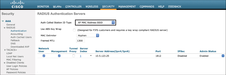
Figure 15-4 Setting the Auth Called Station ID Type
Step 2. Navigate to the WLAN where you wish to implement client authentication. This can be done in the WLANs > WLAN ID > Security > Layer 2 menu. Figure 15-5 illustrates this step.

Figure 15-5 Configuration of the WLAN Security Features
As shown in Figure 15-5, the key security features to configure are the Layer 2 Security and Security Type options. Layer 2 Security should be set to WPA2+WPA3 (this is the default) and Security Type should be set to Enterprise (this is also the default; the other option here is Personal, which will change the security profile to use pre-shared keys). The Enterprise option ensures that 802.1X is used between the client and the controller.
Correct configuration of the security parameters can be confirmed by clicking the General tab under the Security menu. Note that the security policies of WPA2 and 802.1X have been correctly implemented, as shown in Figure 15-6.

Figure 15-6 Confirming the Correct Security Configuration on the WLAN
IOS-XE controllers (such as the Catalyst 9800) can be configured in a similar way by navigating to the Configuration > AAA menu. From here, there are two options: (1) directly configure the RADIUS server configuration and (2) launch the AAA Wizard option. Figure 15-7 illustrates what is seen after launching the AAA Wizard.
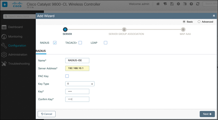
Figure 15-7 Configuring the RADIUS Server Through the AAA Wizard in IOS-XE
Once the RADIUS server has been defined, click Next. On the Server Group Association screen, select the dot1x type pull-down option, as shown in Figure 15-8.

Figure 15-8 Configuring the Controller to Use a RADIUS for Client Authentication (802.1X)
The last step is to assign the correct server to Assigned Server Groups. The purpose of this step is to allow different RADIUS servers to be used for different purposes, such as wireless client 802.1X authentication versus management login authentication services (discussed in more detail in Chapter 17, “Device Hardening”).
Step 3. On the ISE server, the wireless controller must be added as a network device (the controller is the authenticator). Navigate to the Administration > Network Resources > Network Devices menu and click +Add. Figure 15-9 shows how to add a wireless controller as a RADIUS authenticator (ensure the same shared secret that was configured in the controller is reflected here).

Figure 15-9 Adding the Wireless Controller as a RADIUS Authenticator
Step 4. Once the RADIUS server has been added, an identity store must be added. While a local identity store can be created on ISE, it is generally considered more scalable to add an external identity store, such as LDAP or Microsoft Active Directory. Figure 15-10 illustrates how an external identity store may be added. In ISE, navigate to Administration > Identity Management > External Identity Sources and click the type of identity source you would like to add with the Add button. Note that each type of identity source will require configuration details specific to the type of service.

Figure 15-10 Adding an External Identity Store (Active Directory in This Case) to ISE
Step 5. The final step is to configure the appropriate authentication rules. In ISE, this is done with a policy set, found in the Policy > Policy Sets menu. Policy sets provide a way to create logical policy rules and conditions for any kind of authentication method. Figure 15-11 illustrates the creation of a policy to allow network access for authenticated users.

Figure 15-11 The Default Policy Set to Allow Authenticated Users Access to the Network
In ISE, policy sets function much like access control lists (ACLs)—they are configured to first match certain conditions and then take an action based on the result. In Figure 15-11, the default policy set condition is configured to match any client trying to authenticate via either MAC Authentication Bypass (MAB) or 802.1X, for both wired and wireless clients. In other words, any client trying to authenticate by one of these means will match the policy statement so that an action can be taken. The action ISE takes is to first confirm the identity of the user by examining one of the available identity sources. In the example in Figure 15-11, the Active-Directory-Server1 identity source is chosen to authenticate the credentials of the user (note that it is also possible to choose all available identity sources with the All_User_ID_Stores option).
If the authentication is successful, an action can be taken, such as accepting the user on the network. If the user is not identified, the default action (shown in Figure 15-11) is to reject the unknown user or just drop the request if the connection to the back-end identity source fails. It is also possible for policy sets to be very granular, both in the conditions that match the rule and in the policy action taken. For example, an option can be added to the policy set condition to look for specific SSIDs or other options.
Implementing Client Profiling
While EAP-based authentication allows the network to validate the user’s credentials, it does not inspect the type of device the client is joining from, nor does it have any knowledge of the device’s behavior—details that could lead to a policy for the device once network access has been granted. In light of this, once authentication has occurred, the next step is to collect as much information as possible about the device and to use this to further enhance the security policy, such as determining the level of access the client should be given, what VLAN the client should be assigned to, or what QoS profile the client should use. For example, profiling may include device hardware identification, such as validating if it is an Apple iOS device, a Samsung Galaxy device, and so on.
Once a device has been profiled, how are network policy decisions implemented to influence security for the device as well as the wider network? Consider an example where a user with valid credentials attempts to use the credentials on an IoT device the user brought from home. While the IoT device may have a valid username and password from the user, the device itself may be violating the company security policy. In this case, once the IoT device has been profiled and correctly identified by the infrastructure, a policy rule could reject the device, even if the credentials are valid. Consider another situation where a corporate policy has been issued against using certain types of mobile devices on the corporate network. A user may bring a non-standard device from home and use private credentials on this device, thinking this is totally valid. Instead of the device being rejected completely, a policy may be implemented that moves this device to an Internet-facing isolated VLAN where it only has access to the Internet, and access to the corporate network is restricted.
The following section describes the function of client profiling in a wireless LAN and how it can be implemented on both the wireless controller and ISE.
Wireless Client Profiling Principles
Cisco wireless controllers support device sensor functionality, allowing them to become aware of physical and software characteristics of the client device. To do this, the controller collects important information about the device so it can then either make a local policy decision or send the collected information via RADIUS to an ISE server where a policy decision can be made centrally.
On the controller, profiling of devices is based on examining a variety of parameters, including its MAC OUI, DHCP option fields, and application-layer characteristics, such as HTTP headers. Profiling and enforcement of the ensuing policy is done on a per-device basis.
Profiling on the controller can be based on any of the following:
Device type (MAC OUI), which helps identify the device as a Windows machine, smartphone, iPad, iPhone, Android, and so on.
Username/password.
DHCP option fields. This feature allows the controller to locally capture DHCP client attributes and send them to ISE via RADIUS Accounting Updates.
HTTP fields (for example, the HTTP User Agent field).
Time of the day, based on what time of the day the endpoint is allowed on the network.
In addition, ISE is able to profile based on additional contextual information from external sources, including the following:
Role of the user, such as which group the user belongs to (from LDAP or Active Directory)
NMAP scan information
NetFlow scans learned from Stealthwatch
Location context, based on the AP group to which the endpoint is connected
After the client is profiled, policy can be enforced based on the following:
VLAN assignment
QoS profile (precious metal profile)
ACLs
AVC policy
Time of day usage
Session timeout value
Figure 15-12 illustrates the process by which a client is profiled and policy is enforced.

Figure 15-12 Client Profiling Process
As illustrated in Figure 15-12, the client-profiling process uses the following steps:
The client authenticates to the network using 802.1X / EAP.
The client device is profiled by the controller and AP. The controller can either perform local policy enforcement or forward the information to ISE in RADIUS attributes for central enforcement.
If ISE is used, it performs posture assessment of the client. This encompasses much more than the controller can accomplish alone. For example, ISE is able to consolidate information for other external sources, such as Stealthwatch (using PxGrid), NMAP scans, and more. Through the multiple lenses, ISE is able to do a holistic posture assessment of the client with greater context and make a policy decision.
In the final stage, policy changes are implemented by the controller (either by ISE or by the controller itself). If the device is permitted on the network, it may be assigned any combination of a VLAN assignment, device-specific ACLs, a QoS profile, a time-of-day usage policy, or an AVC policy. If the device is rejected, access to the network is completely restricted.
Configuring Local Client Profiling on the Wireless Controller
On an AireOS wireless LAN controller, client profiling is configured through the following steps:
Enable local client profiling on the WLAN.
Configure the profiling policy.
Enable the profiling policy on the WLAN.
Figure 15-13 illustrates how client profiling is enabled in the AireOS controller.
Step 1. Navigate to WLANs > Advanced and enable the two options under Local Client Profiling. Note that the two options are DHCP Profiling and HTTP Profiling. Enabling these features allows the controller to examine the DHCP option fields and HTTP headers to further refine the client profiling. Notice on the same configuration menu there is an option for Radius Client Profiling. This is only used in conjunction with ISE when the profiling is handled centrally.

Figure 15-13 Enabling Local Client Profiling on the WLAN
Step 2. In the second step, a policy is created. This is done by navigating to the Security > Local Policies menu. In the example shown in Figure 15-14, a policy is created to identify traffic from video game consoles using the Device Type drop-down menu. In this example, two policy identifiers are added—one for SonyPS4 and another for NintendoWII.
With the match criteria enabled, the next step is to define how the controller will handle these clients. The same menu shown in Figure 15-14 lists various options, including assigning ACLs, a VLAN ID, or a QoS profile for matching clients. In this case, the controller will map the clients to VLAN 40 as traffic exits the controller, and traffic will be assigned to the Silver (best effort) QoS class. There are also other options, such as time of day when the policy is active.
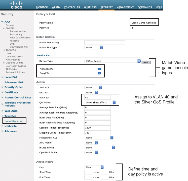
Figure 15-14 Configuring the Client Profiling Policy
Step 3. The final step is to add the newly created policy to the correct WLAN. As shown in Figure 15-15, this can be done on the WLANs > Policy-Mapping menu. Here, the policy for Video-Game-Consoles that was just created is added to the correct WLAN.

Figure 15-15 Attaching the Profiling Policy to the WLAN
The example shown in Figure 15-15 demonstrates how the controller can be used to profile a client locally; however, using ISE for central profiling opens up many new profiling dimensions that a controller on its own does not have. For example, using ISE, it is possible to combine external probe data from multiple sources, including SNMP traps, DNS probes, NetFlow probes, Network Scan probes (NMAP), and others.
To enable ISE profiling, ensure that the Local Client Profiling options are disabled and that Radius Client Profiling is enabled on the controller (as shown in Figure 15-16).

Figure 15-16 Configuring the Controller for RADIUS-Based Client Profiling Using ISE
Note
As of AireOS 8.7.x, the WLC sensor is limited to sending only DHCP Option 12 (host-name) and Option 60 (dhcp-class-identifier) to ISE. Therefore, if additional DHCP attributes are required to more fully profile endpoints, it is recommended to use a DHCP probe to capture all required options. The device sensor features in Cisco IOS-based devices do not have this same limitation.
Implementing BYOD and Guest
Bring Your Own Device (BYOD) and guest are popular use cases for wireless networks. When you stop by your favorite coffee shop and open your laptop, you likely expect to be given free wireless access after accepting the disclaimer on the coffee shop’s guest portal and be granted unfettered access to the Internet. This service is almost ubiquitous in retail, restaurants, and even in public areas of well-connected cities. While guest deployments are often used in public hotspots, they are also widely deployed by companies to support temporary guests and contractors.
BYOD refers to users who bring their own devices from home. At first, BYOD devices are generally considered untrusted and are given limited network access until they are properly onboarded through a guest portal and certain security measures are implemented, at which point the devices are considered trusted and are given wider network access. From the perspective of the wireless infrastructure, BYOD is simply a method of onboarding untrusted devices through a guest WLAN, allowing them to self-register on a guest portal such as ISE, and then implementing the correct security controls and software on the client.
This section examines how wireless controllers and ISE work together to onboard clients through a guest portal and how supplicants and certificates can be deployed to clients as they join the wireless network.
Implementing BYOD and Guest
Guest wireless connectivity involves providing limited network access privileges to an unknown or untrusted user. One important consideration is to decide what type of security will be implemented for the guest (and by extension the BYOD) network. Clearly, different types of authentication are possible. An EAP/802.1X method may be chosen, but this has a drawback that each user will need to request an account and manually deploy a supplicant before even being connected to the WLAN—something that may not be attractive to an IT department that is trying to simplify and streamline the whole process of supporting devices brought from home.
While an SSID using 802.1X authentication for clients is much more secure than an open SSID (a WLAN without security), an open SSID has the advantage that it can be used in conjunction with other security mechanisms, such as a guest portal or VPN. For BYOD users, the open SSID is typically only used during the initial onboarding process, after which the client is moved to a protected SSID.
Note
In some cases, a pre-shared key (PSK) is used for guest networks. This is common at large conferences where all attendees are given the same PSK for the wireless network. Obviously, this doesn’t offer much security because everyone with the same encryption key could easily decrypt anyone else’s traffic. However, the PSK approach does have the benefit of keeping other devices off the network and exhausting DHCP resources.
One of the most common techniques to handle wireless guests, as well as onboard BYOD clients, is through the use of a guest portal. Using this approach, when users connect to the network, they are immediately redirected to a secure captive portal that asks them to agree to the terms and conditions of use of the network, called the Acceptable Use Policy (AUP), and in some cases, to enter or set up new credentials. Offering free access in this way accomplishes the following benefits for companies:
Drives customer loyalty and dwell time at the location
Allows the vendor to be legally compliant through the use of a disclaimer that the user must accept
Allows the vendor to engage with visitors
The key design consideration when deploying BYOD is to decide how the onboarding guest portal and authentication will be handled. From a high-level perspective, there are two common methods:
The following sections examine these two redirection methods.
Local Web Authentication (LWA) with the Wireless Controller
LWA is a guest mechanism that allows a client to be redirected to a web authentication portal directly from the wireless controller. Specifically, LWA requires the controller to (1) enforce ACL match criteria that identify traffic sent to a guest portal and (2) redirect users to the guest portal URL without relying on a central server for this function (which is the main difference with CWA). This doesn’t imply that the guest portal must actually be on the controller; rather, the redirect to the guest portal must be on the controller (with LWA the portal can be either on the controller itself or another server).
With LWA, when a BYOD client connects to the WLAN, the controller intercepts the connection and redirects the client’s first web URL to either an internal or external portal where the user can be asked either to enter authentication credentials or to accept the AUP. The controller then captures the credentials and authenticates the client either using a local user database or through an external RADIUS server. In the case of a guest user, an external server such as ISE is required because the portal provides options for device registration and self-provisioning.
Note that with LWA, the web portal can reside either directly on the controller itself or on another remote server. As mentioned earlier, the thing that makes LWA “local” is the handling of the ACL that matches traffic to send to the portal and the URL redirect, not the location of the portal.
LWA works as follows:
The user is associated with an open SSID that uses web authentication or an AUP.
The user opens a browser or is automatically redirected by a pre-WebAuth ACL on the controller. The pre-WebAuth ACL generally matches any web traffic coming from the client’s web browser and also permits DNS and DHCP access for the client.
When the ACL is matched, the controller redirects the client to either an internal or an external guest portal.
The user is asked to enter authentication credentials on the portal or to accept the AUP (or both). The guest portal redirects the user back to the controller, along with the provided credentials (if an external portal is used).
The controller authenticates a guest user either through a local database or via RADIUS or LDAP to an authentication server.
The controller redirects the client back to the original URL that was entered in the web browser.
Figure 15-17 illustrates LWA with the controller providing the web authentication portal locally (an external guest portal may also be used with LWA, but this is not shown in Figure 15-17).

Figure 15-17 The LWA Redirect and Authentication Process
To configure LWA on an AireOS controller, use the following steps:
Step 1. Create an Open SSID WLAN that will be used for BYOD clients. This WLAN will employ specific ACLs on the controller that trigger URL redirection of the client toward the authentication portal (which can either be on the controller or a remote portal). In the following example, a WLAN called BYOD has been created.
Step 2. In the next step, Layer 2 security should be set to None. This means no 802.1X or PSK will be used on this WLAN. The reason is that BYOD requires open access to the SSID so the client can be onboarded. Figure 15-18 illustrates the Layer 2 security screen. This screen is accessible from WLAN > Security > Layer 2.

Figure 15-18 Configuring Layer 2 Security on the LWA BYOD WLAN
Step 3. An ACL must be configured on the controller to trigger the URL redirect. With URL redirect, the ACL is designed to trigger when a connection is denied (typically the implicit deny statement at the end of the ACL). Other permit criteria in the ACL are used to allow DNS and DHCP traffic between the client and network services without causing the client to be redirected to the authentication or AUP portal. Figure 15-19 illustrates an ACL that will be used to redirect traffic. Take note of the deny statement at the end that will be used for redirection.
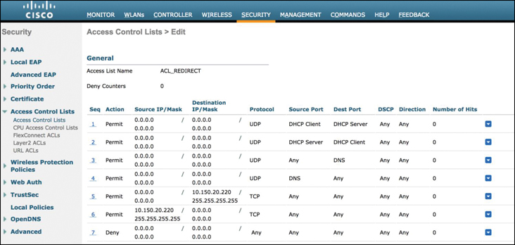
Figure 15-19 Configuring ACL That Will Be Used to Redirect Clients to the Authentication Portal
Note
One difference to be aware of between AireOS and IOS-XE controllers (such as the Catalyst 9800) is that IOS-XE will trigger the URL redirect based on matching a permit statement, whereas AireOS controllers trigger the URL redirect based on matching a deny statement.
Step 4. In this step, the L3 security rules are implemented. Because the redirect happens at Layer 3, this is where the ACL and redirect information must be configured. Under WLANs > Security > Layer 3, configure the Layer 3 Security policy to be Web Policy. This is illustrated in Figure 15-20.

Figure 15-20 Configuring Layer 3 Security on the LWA BYOD WLAN
Notice in Figure 15-20, there is a pull-down menu to select the Preauthentication ACL. This is the security ACL defined in Step 3. As soon as a client web connection triggers the deny statement matching the ACL, the client will be redirected to the authentication portal.
It is also important to decide where the BYOD portal will be located. LWA supports both an internal portal on the controller itself or an external portal such as ISE. Both have their pros and cons. Implementing LWA using the controller’s internal portal is quick, cheap, and easy to deploy, but it’s less flexible and less scalable than an external portal such as ISE. Under the Web Auth type pull-down shown in Figure 15-20, you can select either Internal (which is the default) or External. If an external server is chosen, the Redirect URL option must be configured. In this example, an external web portal with the URL https://my-ise-portal/login.html is being used.
Also, note there are several portal configuration options available on this menu. The Authentication option will present an authentication request to the client, whereas Passthrough will simply ask the user to click Accept and accept the AUP before proceeding.
Figure 15-21 illustrates how the redirect portal differs for both the Authentication and Passthrough options.
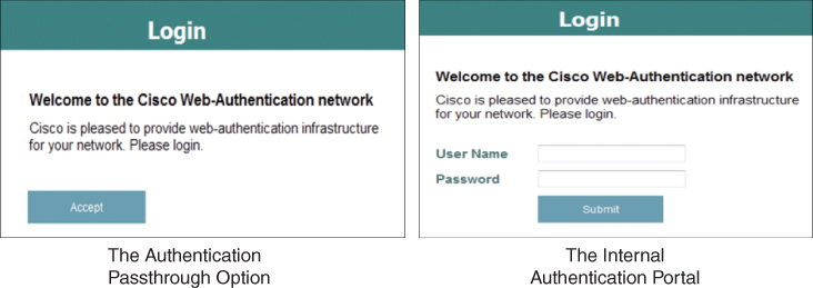
Figure 15-21 The Authentication Portal Options
By default, the controller uses a self-signed certificate. If the portal certificate is not signed by a well-known authority, the client’s browser will see a security alert and will be forced to manually accept the certificate.
Step 5. Finally, it is important to select how users will be authenticated. There are several options, including the use of a local database on the controller and the use of an external RADIUS or LDAP server. Even if a global AAA server has been configured on the controller, it is quite common to configure a different one dedicated for BYOD clients. If this is the case, it is necessary to override the global AAA RADIUS configuration and use a different one for BYOD.
To select an alternate AAA server for BYOD, navigate to WLANs > Security > AAA Servers and select the RADIUS server that will be used for BYOD. Figure 15-22 illustrates this configuration step.
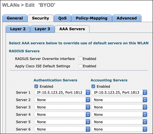
Figure 15-22 Configuring the AAA Override Settings
If a dedicated RADIUS server is used for BYOD, the WLAN must be configured to override usage of the global RADIUS server. This is done by navigating to WLANs > Advanced and selecting Allow AAA Override.
Local Web Authentication on an IOS-XE Controller
Configuration of LWA on an IOS-XE controller is very similar to AireOS, with a few exceptions. To begin configuration, navigate to Configuration > Security > Web Auth. Once the Web Auth Parameter Map is created, it can be configured with similar features that are used in AireOS, as shown in Figure 15-23.

Figure 15-23 Configuring LWA on an IOS-XE Controller
One interesting difference to be aware of is that the passthrough option (where the user only has to accept the AUP) is called Consent on the IOS-XE controller. By clicking on the Advanced tab, other features, such as the redirect URL and the portal IP address, can be configured.
Local Web Authentication with an Anchor Controller
An approach commonly used in conjunction with guest and BYOD is the use of anchor controllers. Anchor controllers were first developed to support client roaming between controllers through the use of an inter-controller L2 tunnel that bridges the client’s 802.11 traffic back to the initial pre-roam controller. This allows IP continuity between controllers instead of forcing a client to obtain a new IP address from DHCP each time it roams to an AP managed by a different controller. With inter-controller tunnels, if a client roams to an AP connected to a different controller, the Layer 2 tunnel between the two controllers makes it appear as if the client is still Layer 3 connected to the first controller (the anchor controller), while Layer 2 is being serviced by the new controller (the foreign controller). In other words, the tunnel stretches the L2 domain from the anchor to the foreign controller.
Over time, this became an elegant way to isolate all guest traffic. Instead of handling each guest user independently on each controller, through the use of an anchor it became possible to funnel all guest or BYOD traffic over the inter-controller Ethernet over IP (EoIP) or CAPWAP tunnels into a centrally located guest anchor. Here, they could be redirected to the guest portal by a single controller, and once allowed onto the network traffic could be forwarded through a protected DMZ interface on a central firewall and then sent to the Internet, ensuring these users were isolated from all corporate traffic.
As discussed, anchors have two key components: foreign and anchor controllers. When a guest or BYOD user connects to a wireless network, the local controller is called the foreign controller, and the one with the guest portal (or redirect to the guest portal) is called the anchor controller.
Figure 15-24 illustrates a general network framework using an anchor controller with LWA.

Figure 15-24 Using an Anchor Controller for LWA
When anchor controllers for LWA are used, traffic from the users is tunneled through the foreign controller to the anchor, meaning the certificate and the authentication portal the client uses are on the anchor, not the foreign controller.
In LWA, redirection is triggered by the anchor, meaning the Layer 3 security redirection and pre-WebAuth ACL are configured there. On the foreign controller, only Layer 2 security features are implemented.
Certificate Provisioning on the Wireless Controller
One thing that makes LWA somewhat complicated is the number of certificates involved. Regardless of whether you use an internal or an external portal, a certificate of some type is invariably required on the controller. Even if a central portal is used, the redirect function on the controller will use a certificate. In fact, if a central portal is used, two certificates will be used: one for the local controller redirect and the second on the portal.
Generally, self-signed certificates are less effective as they require manual acceptance of the certificate and an override of the client browser’s native security policy. This can be especially problematic when a remote portal is used, as the client will be forced to manually accept two certificates.
On the AireOS controller, certificates for LWA can be found in the Security > Web Auth > Certificate menu. Here, the default self-signed certificate is identified, as well as an option to import a new trusted SSL certificate (see Figure 15-25).

Figure 15-25 Web Authentication Certificates in AireOS
In IOS-XE, certificate management can be found in the Configuration > Security > Web > Certificate menu (see Figure 15-26).
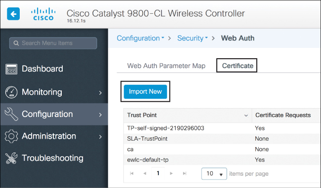
Figure 15-26 Web Authentication Certificates in IOS-XE
LWA and Self-Registration
External centralized BYOD and guest portals offer many advantages over local portals on the controller. For example, ISE offers great flexibility in how portals can be used for different use cases. For example, ISE allows you to create the following types of use-case driven portals:
Hotspot guest portals
Self-registration (a self-registered guest portal is typically used for BYOD clients)
Sponsored guest portals
A self-registration portal is an effective tool for BYOD deployments as it allows users to create their own accounts, which are then added to the ISE identity store.
In ISE, navigate to Work Centers > Guest Access > Portals & Components to configure one of these portal options. Figure 15-27 illustrates this configuration page in ISE (ISE version 2.6 is illustrated).
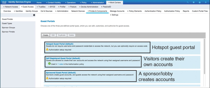
Figure 15-27 ISE Guest Portal Options
The ISE self-registration option allows granular configuration of how clients may register with the portal, the AUP they are presented with, and so on. Figure 15-28 illustrates this capability in ISE.

Figure 15-28 Setting Up an ISE Self-Registration Portal
Central Web Authentication (CWA) with ISE
Central web authentication is similar to LWA in many respects, with the main differences being that the URL redirect and pre-WebAuth ACLs are centrally located on ISE (instead of on the controller) and authentication instructions are communicated to the controller through RADIUS. Thus, with CWA, there is no need for a local web-auth certificate on the controller. This obviously makes the controller deployment simpler in many ways but does require an external authentication server and portal. For example, if there are many controllers in a large organization, it is probably impractical to process the BYOD redirects and ACLs on each controller. Additionally, only one certificate is needed on the central web portal instead of two (in LWA there is one certificate on the controller and another on the authentication portal). On the other hand, CWA requires the deployment of a central authentication server, such as ISE.
The CWA process works as follows:
A client is associated with an open SSID that is using CWA. MAC filtering is enabled on the controller for this WLAN.
The controller forwards the MAC address of the client as an authentication request to ISE.
ISE is configured in such a way that even if it doesn’t know the MAC address of the client, it sends a redirect URL and an ACL to the controller.
The user opens a browser. The URL request hits the ACL on the controller and is denied, triggering a URL redirect to ISE.
The user is redirected to the ISE BYOD/guest portal. The user is authenticated and/or is presented with the AUP.
ISE sends a RADIUS CoA (Change of Authorization—UDP port 1700) message to the controller, informing it that the user has correctly entered credentials. Other RADIUS attributes are optionally sent to control the client’s behavior (such as ACLs).
The user is either redirected to the original URL or does this manually.
This process is illustrated in Figure 15-29.

Figure 15-29 How a Client Authenticates Through CWA Using ISE
The key difference with LWA is that there is no preconfigured Layer 3 security policy on the controller—both the ACL and the web-preauth configuration are centralized on ISE and are communicated to the controller through RADIUS, with the final security policy being communicated to the controller with a CoA message from ISE.
The following are the steps to configure CWA on an AireOS controller:
Step 1. On an AireOS controller, CWA is configured similarly to LWA but with some subtle differences. On the WLANs > Security > Layer 2 menu, enable the MAC Filtering option, as shown in Figure 15-30.
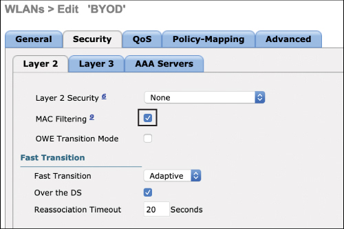
Figure 15-30 Configuring Layer 2 Security for CWA
Step 2. Disable all Layer 3 security (as CWA relies on Layer 2 security, not Layer 3). This is shown in Figure 15-31.
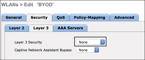
Figure 15-31 Configuring Layer 3 Security for CWA
Step 3. Under the WLANs > Advanced menu, configure the NAC State to be ISE NAC, which will allow ISE to be used as the central authentication mechanism, as shown in Figure 15-32.

Figure 15-32 Configuring the NAC State to Use ISE NAC
You might be wondering how CWA works if anchor/foreign controllers are used. Recall that for LWA, the ACL and redirect URL are implemented on the anchor controller, whereas the foreign controller simply has the responsibility to forward traffic at Layer 2 to the anchor. However, because CWA relies on Layer 2 MAC authentication (not Layer 3), the redirect from ISE must be sent to the foreign controller, not the anchor controller. The foreign controller, in turn, passes these attributes (the pre-WebAuth ACL and the redirect URL) to the anchor controller. At this point, the anchor takes over and manages the redirection to the ISE guest portal.
It is important to keep in mind that LWA happens purely at Layer 3 whereas CWA happens at both Layer 2 and at Layer 3, with the Layer 3 portion performed by ISE. From a high-availability perspective, LWA is fairly limited, especially if the controller’s own portal is used. On the other hand, because CWA uses ISE as its back-end system, it also inherits the natural resiliency capabilities of ISE clustering. For example, if a first ISE Policy Services Node (PSN) doesn’t reply, another PSN can be used from the cluster.
LWA has its advantages as well, though. The local guest portal is free and comes included with the controller, whereas CWA requires investment in external portal.
Native Supplicant Provisioning Using ISE
Once a BYOD client has been authenticated through ISE, it is often necessary to provision a properly configured supplicant to the client so it can become part of a secure 802.1X WLAN. Client provisioning is a capability on ISE that allows users to download resources and configure agent profiles. You can configure agent profiles for Windows clients, MacOS clients, as well as native supplicant profiles for personal devices.
Generally speaking, client provisioning resources are downloaded to endpoints after the endpoint is authenticated and connects to the network. Client provisioning resources consist of compliance and posture agents for desktops and native supplicant profiles for phones and tablets. Examples of provisioning resources include Cisco AnyConnect and Advanced Malware Protection (AMP) software.
Native supplicant profiles can be created in ISE that enable users to bring their own devices and maintain an acceptable level of security. When the user signs in, ISE uses the profile you associated with the user’s authorization requirements to choose the necessary supplicant provisioning wizard. The wizard then runs and sets up the user’s personal device so it can access the network.
To configure a native supplicant profile in ISE, navigate to the Policy > Policy Elements > Results > Client Provisioning > Resources menu and choose +Add. When the menu opens, choose Native Supplicant Profile, as shown in Figure 15-33.
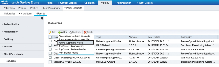
Figure 15-33 Configuring the Native Supplicant Profile in ISE
When this is selected, you will have the option to create a new wireless profile. When you click +Add, a window similar to Figure 15-34 opens. This menu determines the SSID and authentication methods you wish the client to use when connecting to the corporate network by programming them into their native supplicant.
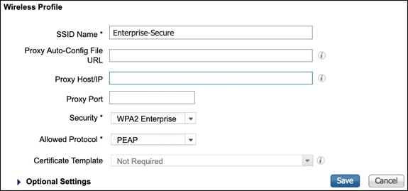
Figure 15-34 Configuring the Native Supplicant Profile for a Wireless Network
Summary
This chapter focused on the implementation of security in wireless LANs. In this chapter you have learned the following:
Implementation options for various EAP types as well as differences between the inner and tunneled EAP methods
How to implement 802.1X and EAP using a AAA server
How to profile a client device using the controller and ISE
How ACL, VLAN, and QoS policies can be implemented on a client after profiling
Fundamentals of guest and BYOD wireless deployments
The function of LWA and various implementation options on a wireless network, including certificate management
The function of CWA and how it is implemented on a wireless network with ISE
How a client can use the self-provisioning feature of ISE to deploy a native supplicant
References
For additional information, refer to these resources:
Which EAP Types Do You Need for Which Identity Projects? https://www.networkworld.com/article/2223672/which-eap-types-do-you-need-for-which-identity-projects.html
ISE Profiling Design Guide: https://community.cisco.com/t5/security-documents/ise-profiling-design-guide/ta-p/3739456#toc-hId--511047482
SE deployment guide for BYOD: https://community.cisco.com/t5/security-documents/cisco-ise-byod-prescriptive-deployment-guide/ta-p/3641867
Web Authentication on the WLAN Controller: http://www.cisco.com/c/en/us/support/docs/wireless-mobility/wlan-security/115951-web-auth-wlc-guide-00.html
Identity Services Engine Guest Portal Local Web Authentication Configuration Example: http://www.cisco.com/c/en/us/support/docs/security/identity-services-engine/116217-configure-ISE-00.html
Central Web Authentication on the WLC and ISE Configuration Example: http://www.cisco.com/c/en/us/support/docs/security/identity-services-engine/115732-central-web-auth-00.html
Central Web Authentication with FlexConnect APs on a WLC with ISE Configuration Example: http://www.cisco.com/c/en/us/support/docs/security/identity-services-engine/116087-configure-cwa-wlc-ise-00.html
Enterprise Mobility 8.5 Design Guide: https://www.cisco.com/c/en/us/td/docs/wireless/controller/8-5/Enterprise-Mobility-8-5-Design-Guide/Enterprise_Mobility_8-5_Deployment_Guide.html
Catalyst 9800 Technical References: https://www.cisco.com/c/en/us/support/wireless/catalyst-9800-series-wireless-controllers/products-technical-reference-list.html
Catalyst 9800 Configuration Examples and Tech Notes: https://www.cisco.com/c/en/us/support/wireless/catalyst-9800-series-wireless-controllers/products-configuration-examples-list.html
Exam Preparation Tasks
As mentioned in the section “How to Use This Book” in the Introduction, you have a few choices for exam preparation: the exercises here, Chapter 18, “Final Preparation,” and the exam simulation questions in the Pearson Test Prep Software Online.
Review All Key Topics
Review the most important topics in this chapter, noted with the Key Topic icon in the outer margin of the page. Table 15-3 lists these key topics and the page numbers on which each is found.
Table 15-3 Key Topics for Chapter 15
Key Topic Element |
Description |
Page Number |
|---|---|---|
The wireless network authentication framework |
370 |
|
The EAP authentication process |
372 |
|
A summary of common EAP methods |
374 |
|
Client profiling process |
381 |
|
The LWA redirect and authentication process |
387 |
|
How a client authenticates on a CWA portal using ISE |
395 |
Define Key Terms
Define the following key terms from this chapter and check your answers in the glossary:
EAP (Extensible Authentication Protocol)
Lightweight Directory Access Protocol (LDAP)
Remote Authentication Dial-In User Service (RADIUS)
Flexible Authentication via Secure Tunnels (EAP-FAST)
Transport Layer Security (EAP-TLS)
local web authentication (LWA)