
Chapter 2
Conducting an Offsite Site Survey
This chapter covers the following topics:
The Effect of Material Attenuation on Wireless Design: This section covers the main materials that you may encounter in standard buildings where Wi-Fi is deployed and their effect on the Wi-Fi coverage.
Common Deployment Models for Different Industries: This section provides an overview of common requirements found for Wi-Fi networks in enterprises, healthcare, hos-pitality, hotspots, warehousing, manufacturing, retail, and education.
Designing with Regulations in Mind: This section provides a summary of the rules found in the FCC and ETSI domains for RF Wi-Fi transmissions.
Choosing the Right Survey Type: This section lists the different types of offsite and onsite surveys.
A Survey of Wireless Planning Tools: This section introduces the main site survey tools types as well as lists the main players.
Conducting a Predictive Site Survey: This section details the steps required to conduct a predictive site survey with Cisco Prime Infrastructure (PI).
This chapter covers the following ENWLSD exam topics:
1.2 Describe material attenuation and its effect on wireless design
1.6 Perform a predictive site survey
1.7 Utilize planning tools and evaluate key network metrics (Ekahau, AirMagnet, PI, Chanalyzer, Spectrum Analyzer)
Radio frequency (RF) propagation depends on the environment, and if you do not know the environment, you cannot possibly design your network properly. This does not mean that you should rush onsite with site survey tools. The site survey starts before traveling, by assessing elements that will help you save time and be more efficient once you are in the building to survey. Proper preparation may even save you the trip entirely. This chapter will cover the key elements of the preparation phase, starting by looking at building materials but also common coverage requirements for most industries and the impact of regulations on your design. You will then learn about the main survey tools for onsite or offsite evaluations. You will then learn how to perform a predictive site survey.
“Do I Know This Already?” Quiz
The “Do I Know This Already?” quiz allows you to assess whether you should read this entire chapter thoroughly or jump to the “Exam Preparation Tasks” section. If you are in doubt about your answers to these questions or your own assessment of your knowledge of the topics, read the entire chapter. Table 2-1 lists the major headings in this chapter and their corresponding “Do I Know This Already?” quiz questions. You can find the answers in Appendix D, “Answers to the ‘Do I Know This Already?’ Quizzes and Review Questions.”
Table 2-1 “Do I Know This Already?” Section-to-Question Mapping
Foundation Topics Section |
Questions |
|---|---|
The Effect of Material Attenuation on Wireless Design |
1–2 |
Common Deployment Models for Different Industries |
3 |
Designing with Regulations in Mind |
4 |
Choosing the Right Survey Type |
5 |
A Survey of Wireless Planning Tools |
6 |
Conducting a Predictive Site Survey |
7 |
1. Which level of attenuation would you expect from drywall (or plasterboard wall)?
About 1 to 2 dB
About 3 to 4 dB
About 6 to 8 dB
About 10 to 12 dB
2. A wireless associate claims to have measured a 25 dB attenuation behind a concrete wall and asserts that the common reference table indicates 12 dB is wrong. What can you tell the associate?
The associate may have measured the attenuation from the middle of the room instead of right behind the wall, thus leading to the discrepancy.
The table is only indicative. Local differences may be found, and this is why surveys are important.
The table is old. Newer walls have metal reinforcement that increases the attenuation.
The table indicates the one-way attenuation, but Wi-Fi communication is bidirectional, so 24 to 25 dB is correct.
3. What is the primary purpose of coverage in a hospital?
Staff mobile devices
Medical machines
Patient and guest Wi-Fi
All of the above
Can’t say without more information
4. What is the maximum EIRP in U-NII-3 for the FCC domain?
100 mW
23 dBm
200 mW
30 dBm
5. You are asked to provide an indication of the number of access points (APs) for a new office without going onsite. What kind of survey best describes this type of estimation?
Predictive site survey
Layer 1 sweep
Passive survey
Proactive survey
6. A junior associate sees on your laptop a program called Chanalyzer and asks what it is used for. What would you answer?
Predictive Active site surveys
Layer 1 sweeps
Layer 3 sweeps
Position APs on a floor plan for channel planning
7. Customers ask in which areas of the building they can deploy their APs based on the result of your predictive survey. What would you answer?
Only in open spaces
Only in open spaces and cubicle areas
Only in hallways and high ceiling areas
None of the above
Foundation Topics
The Effect of Material Attenuation on Wireless Design
One of the first elements you should collect in preparation of a site survey is a map of the area to cover, along with scale and an idea of the building and material encountered. Covering an office building is not the same as covering a warehouse, and knowing the line of business and activity type of your customer will also provide precious information about potential issues and limitations.
Even before going onsite, you should have a clear idea of the type of coverage needed (Chapter 3, “Conducting an Onsite Site Survey,” will help you make this assessment), data, real-time applications, and location-based services. You should also get to know the type of building you are designing for. This knowledge will help you approximate the number of APs needed. Knowing the number of APs will help you plan the time it will take to survey the facility.
Each AP cell area is limited because RF signals get attenuated as distance increases from the AP. The loss of signal strength is more pronounced as the signal passes through different objects. Therefore, knowing the expected obstacles will help you estimate each cell size.
AP radio signals are expressed in dBm. dB stands for decibels, a unit to measure relative power on a logarithmic scale, and m stands for milliwatt. Thus, the dBm scale measures the transmitted or received power, using 1 milliwatt as the reference value. Because the dB scale uses logarithms, it is not linear (which means that dividing or multiplying the value by 2 does not mean half or twice the power). Instead, doubling the power is represented by a gain of 3 dB (and, symmetrically, halving the power is represented by a loss of 3 dB). Multiplying the power by 10 is represented by adding 10 dB, and dividing by the power by 10 is represented by subtracting 10 dB. For example, a transmit power of 20 mW can be represented as 13 dBm. This is because you start from a 1 mW reference, which is 0 dBm, as you have nothing more or less than the reference starting point. You then multiply that reference power by 10, thus reaching 10 mW (or [0 + 10] dBm), and you double that power, thus reaching 20 mW (or [0 + 10 + 3] dBm).
Note
When you want to express the AP power, you use the milliwatt reference, thus stating, for example, “the AP radio is set to 13 dBm.” When you evaluate the effect of an obstacle on your signal, you simply express the attenuation on the decibel scale (not the dBm scale), because the unit of reference (milliwatt) is the same on both sides and becomes irrelevant. Expressing gain or attenuation in “dBm” would be considered wrong.
Each obstacle and each material absorbs some of the signal. In the Cisco world, there is a common reference table, represented in Table 2-2.
Table 2-2 Common Obstacles and Their Estimated Attenuation Values
Object in Signal Path |
Signal Attenuation Through the Object |
|---|---|
Plasterboard wall |
3 dB |
Glass wall with metal frame |
6 dB |
Cinderblock wall |
4 dB |
Office window |
1–3 dB |
Metal door |
6 dB |
Brick wall |
8 dB |
Concrete wall |
12 dB |
Phone and body position |
3–6 dB |
Phone near field absorption |
Up to 15 dB |
Although you should know this table, you also have to keep in mind several additional elements:
Do not take these values as absolutes. You will find other tables, from other vendors, with slightly or widely different references. Do not think that one vendor is right and the other is wrong; they just used different walls for reference.
Different countries have different building practices. A brick wall that represents 8 dB attenuation in one country may be labeled as 12 dB attenuation in another, because the brick is different—thicker, with additive isolating material, with or without inner air chambers, and so on.
Even within a particular region, attenuation may change over time. For example, a plaster wall in a dry and air-conditioned location may display less attenuation than the same wall in midseason when the air (and the wall) humidity level is higher.
These attenuation values are usually measured far from the wall. There is a major difference between near field attenuation and far field attenuation. If you position your AP in the middle of a medium-sized room and then go to the middle of the neighboring room, you may measure an attenuation matching Table 2-2. However, if you move your laptop or measuring device just near the wall separating both rooms, the attenuation may suddenly become much higher, by 15 dB (as per the table), but may be also dramatically more (as much as 55 dB). This is because the attenuation affects the measuring device near field. In simple terms, the wall absorbs most of the energy received by your device.
Therefore, use Table 2-2 as a reference point but not as an absolute reference. Also keep in mind that each site surveyed will have different levels of multipath distortion, signal loss, and signal noise.
Common Deployment Models for Different Industries
These environmental constraints are also associated with standard practices. For example, hotels usually do not require high-density coverage in guest rooms, and this is because they expect a limited number of guests in each room. By contrast, schools usually expect a high density of devices in each classroom. Knowing the common requirements for standard verticals will help you pass the exam and will also help you ask the right questions when facing a new project.
Enterprise Office
In an enterprise office, mobile users require the same accessibility, security, quality of service (QoS), and high availability as wired users. Most of the time, you will be facing an existing network that needs to be upgraded for more performance, a higher user density, or more throughput. The office environment is ever-changing by nature. New applications and new devices may appear at any time when the business needs them, and the network is expected to be ready to support them from day 1. Enterprise Wi-Fi environments show two main trends:
Increase in devices: Workers commonly get laptops (wired and fixed stations become less common), and users also bring phones and tablets. The wireless space becomes crowded with devices that associate and may consume airtime and bandwidth, even when idle. You need to determine with your client what types of devices are allowed to connect to the wireless network and evaluate the associated bandwidth requirements.
Increase in mobility needs: Enterprise office users are traditionally thought of as not very mobile. In this context, “not very mobile” refers to what is called “nomadic roaming.” Users work from one station, then move to another station and expect the connection to be available at their new location. The efficiency of the roaming (active communication while moving from one AP to the next) is not a big concern in that case, even if some applications are running in the background while the user moves. Many data-oriented applications are tolerant to changes in the throughput. However, these habits are changing. Real-time communication tools (video calls or conferences) have become common, and people pace or walk, looking for a quieter spot, while using these tools. You should evaluate this trend and treat these environments as requiring high efficiency (real-time application quality) everywhere.
During the initial discussion with your customer, you need to approach the possibility of future changes, and at a minimum make sure that your customer understands the possibilities of your deployment in each area. Your survey and the design specifications must clearly state the expected user density and the expected average throughput in every covered area. You should also explain to your customer that a wireless network is designed for a target throughput, and that adding throughput is not just about adding more APs later. Adding more throughput would typically mean conducting a new site survey. If any change of user density is expected, it is better to take this possibility into account early.
Office environments often have difficult areas, such as lobby areas designed with large atriums. Providing coverage there is expected but might prove challenging, because the atrium is an open space. The signal from many APs around the atrium, on different floors, may bleed through and travel far in the open space. The result may be that too many APs are detected from the atrium area. You may have to plan ahead and take this difficulty into consideration, by positioning the APs far from the atrium area, keeping only one or two APs specifically to cover the open space.
Another type of issue may be encountered in large meeting rooms or auditoriums, where you may expect a very high density of users, sometimes several hundreds. Because of the size of this type of room, using standard APs with internal antennas is often not feasible. You may have to come up with creative solutions, such as directional antennas or a high density of APs set to low power.
Last, you may need to know if the office building is entirely owned by one single corporation or if your client occupies only a suite on one floor. If your client occupies only a suite on one floor, then you should expect RF neighbors you cannot control. They may use all possible channels and be set to maximum power. You should be ready to work around these limitations by measuring neighboring systems’ signal levels and rethink your channel plan accordingly.
Small or Home Offices
Small or home offices may need a single AP, in which case onsite survey is unlikely to be needed (survey is needed as soon as a network has more than one AP). However, they may also suffer from the same challenges as offices in a shared building: neighbors and their RF systems. Be prepared to respond to requests to verify the RF environment. Cisco APs, even when designed for remote or small offices, can use Radio Resource management (RRM) to select the best channel and power level, but the process is not magical. In a high-density dwelling, your survey may conclude that there is simply no “good” channel to choose from, and the settings will only pick the “least worst” option.
Healthcare
Healthcare site surveys are often time-consuming, because almost every hospital is a multistory building with numerous small rooms. The survey must be thought of as a three-dimensional exercise, which is intellectually difficult when working with two-dimensional floor plans. Hospitals also have special rooms, like trauma and X-ray areas, where the walls might be lead-lined and completely stop RF signals. Last, hospitals have restricted access policies to some areas. Typical examples are surgical rooms and clean rooms. It is often difficult to obtain access to these rooms, and when you do, you may not be allowed to carry your laptop. You may still be expected to provide wireless access inside these areas.
Healthcare environments often require the WLAN to support a large number of application types: paging, voice, a wide range of data applications (such as mobile carts and patient monitoring devices), and location services. These applications may be critical for keeping patients alive, and your design should ensure optimal signal to every corner of every room, even when all doors are closed.
Check the Wi-Fi client type. Healthcare environments are often a mix of very recent applications or devices and older devices (only supporting older protocols such as 802.11b/g) that simply cannot be changed or replaced easily and still need to work in the new WLAN. You should also expect competition for the RF space. Some devices may be Wi-Fi-capable and consume a lot of bandwidth (for example, portable X-ray machines, sending high-resolution images, sometimes in real time, echography machines, and electrocardiography [ECG] machines). These devices may also use the same spectrum as Wi-Fi but with other protocols and, therefore, become sources of interference for your system.
Hospitals also use laptops on wheels (also called workstations on wheels, or WoWs) that are pushed throughout the hospital. They may be transmitting while moving and therefore you need to design your network by taking roaming paths and required throughput into account. Hospitals also often provide public Internet access service for their patients and visitors. This service may compete with the staff network.
Another common use case for wireless in healthcare environments is location tracking for assets (for example, blood pumps, beds, wheelchairs, and other assets that need to be located quickly), wandering patients, and to associate nurse and patient locations for billing purposes.
A last concern is aesthetics. It is common to be asked to hide the APs from view. Hiding APs may prove challenging in hospitals that do not use ceiling tiles. You may find creative solutions, such as hiding the APs in the walls, but even this type of solution may be difficult to implement in an environment where noise is banned and drilling through walls is not acceptable.
Hospitality and Hotels
Hotels are much like hospitals in their building construction and configuration (that is, usually multiple floors with many rooms). Beyond guest Wi-Fi (which may include video streaming as a standard service), hotels have started using WLANs to support data collection devices for taking inventory of things such as minibars, staff location, equipment status, and more. Wi-Fi keeps being rated as one of the most important services a hotel can provide (far more important than free breakfast or parking). Beyond requiring the engineer to look at the survey three-dimensionally, hotels present additional concerns about throughput and security. The high number of walls separating guest rooms decreases the range of APs and thus increases the need for more APs. Hotels want to offer their guests fast, reliable Internet access, which means fewer users per AP. This can easily be achieved in rooms. However, hotels often have restaurants and retail and convention areas, where user density may be much higher. You should carefully evaluate the maximum number of guests in these areas as well as the applications they may be expected to need. Running new cables is much more expensive than adding a few extra APs. Also, these are usually public places and thus susceptible to theft and vandalism. A common requirement is to properly secure APs to ceilings or walls or to hide them above the ceiling.
Network security may also be a concern. The main preoccupation is often “zero support.” The hotel guest should be able to connect to the wireless network without requiring external assistance, which means that connection security is often very limited to allow for compatibility with the largest possible number of devices (for example, no Layer 2 security and web authentication for usage tracking and billing, strong firewalling, and sometimes website filtering).
Hotels also have many of the same concerns as hospitals regarding aesthetics. APs may need to be hidden in the walls or ceiling, where possible, or behind elements of the furniture.
Hotspots
The word hotspot refers to any type of 802.11 wireless access in public areas that’s usually intended for guests or patrons, although the service may be provided without any purchase expectation. There are close to 500 million of those networks worldwide. Some provide a free connection, while others are built to generate revenue. The quality of the wireless coverage needed and the investment in the wireless infrastructure may be different depending on the model. Make sure to examine with your customer the hotspot goals and expected results, including the type of application expected to be supported and the maximum user density.
Education
The user density and data device types may be different depending on the type of school you are requested to cover. In grade schools, wireless data devices are usually laptops provided by the school to the class. In middle schools, you may see a larger proportion of personal devices, such as smartphones or laptops. In high schools and university, personal devices will be common. Many students will carry several devices. Most of these devices will be configured to connect to the school network and will associate as soon as they are in range. They may then perform automatic updates and stay connected all day long, even if the student is not actively using them. The devices, by their density, may place a serious strain on the wireless infrastructure and may force you to set up a security policy by which each student has credentials, allowing one session at a time. You may also have to implement congestion policies. A common design is to account for 25 to 30 students (students, not devices) per AP, thus sometimes resulting in more than one AP per classroom.
School buildings present the same issues as large office buildings and hospitals. The survey needs to be conducted with 3D in mind, as signal will bleed through floors and ceilings. You are also likely to face large atriums and large auditoriums with high student density, where the issue will be too much signal from too many APs. Here, again, you may need to use directional antennas to increase the AP density without creating too much interference.
Another concern in education is that students may be curious and sometimes destructive. An antenna mounted to the ceiling in a hallway and an AP with a flashing light can attract attention. In most cases, educational facilities must have the equipment installed in the most inconspicuous manner possible. National Electrical Manufacturers Association (NEMA) enclosures with enclosed locks can help prevent tampering or theft. You can use these enclosures in locations where APs cannot be hidden easily or in a truly high-risk area.
Retail
Retail, just like hospitality, has Wi-Fi needs for two populations: staff and customers. For staff, wireless data collection devices offer real-time updates to the store databases and the ability to place registers and printers throughout the store for special events (such as a sidewalk or tent sale) without having to worry about cabling. Some stores may conduct inventory at night (sometimes with high device density at that time). These inventory devices may be barcode scanners (possibly limited to 802.11b/g) or 802.11a/b/g/n/ac tablets. Some may use VoWLAN during daytime operations, thus requiring real-time application quality coverage throughout the entire building. Some may consider guest Wi-Fi as critical to their business, but usually with data throughput. You should spend some time understanding the store’s practices.
Stores must also often comply with specific regulations, such as those from the Payment Card Industry (PCI). These requirements may create additional constraints in the type of encryption and the characteristic of the Wi-Fi cells deployed for the staff. Another concern within the retail industry is the close proximity of the store to other RF devices. Some locations might stock and display RF devices in the store, such as satellite systems, baby monitors, and cordless phones. Others may use non-Wi-Fi cameras or cordless phone systems. Many of these devices might operate in the 2.4GHz range, and some might operate in the 5GHz range. APs should not be installed next to this type of equipment because they typically have a higher transmitter power. Retail stores might also be located in malls or strip malls where other Wi-Fi users might be operating.
Last, keep in mind that coverage may be needed on loading docks or inside trucks at the loading dock. Depending on the WLAN design, there might be enough RF coverage extending to the outside of the buildings to accommodate this need, but it should be factored into the design. You need to observe the customer behavior. If the staff scans goods from inside the trucks while loading or unloading, you need to plan for coverage accordingly. Trucks may have a metallic trailer, and providing coverage inside the truck might require a directional antenna. The goods may absorb the signal, so you might need to place your APs strategically to work around the absorption issue. Here again, observing customer habits is key to a good design.
Warehousing
The same coverage concerns for retail should be factored in for warehouse coverage. There might be a limited number of users during the day, but when a shipment comes in (or multiple shipments come in at the same time), many or all users might be operating at the same time. Coverage areas are generally large, subject to a lot of multipath distortion or RF interference because of concrete floors, metal roofing, and metal shelving. Cell size is more important than data rates because warehouse applications are generally transaction driven, with small packet sizes. Cell coverage overlap needs to be from 10 to 15 percent. The usage is not very high, but the users are highly mobile and must roam often.
There is no way of determining the distance of a signal without knowing the type of inventory. Different types of stock either reflect or absorb the radio frequency. It is important to talk with all people expected to use the WLAN. A forklift driver, for example, can have an accurate assessment of how stock levels vary over time (and what goods should be expected). A warehouse at a 50 percent stocking level has a much better RF footprint than the same warehouse has at 100 percent. Goods such as lead-based paint will reflect the signal, while paper or pet food will absorb the signal and reduce the usable cell size. If widespread information gathering is not possible, the plan should compensate for the potential increase in stock.
Additionally, some warehouses need their Wi-Fi network to operate primarily when inventory is full (for forklift and product retrieval) and other warehouses need their Wi-Fi network to operate primarily when inventory levels are low (for inventory reordering procedures), and some warehouses need both. Make sure to communicate with your customer to understand how the Wi-Fi network is expected to be used in order to design around the warehouse environment when it will be expected to operate. Not all use cases will warrant a functional Wi-Fi network when inventory levels are full.
Warehouses and distribution centers typically have maximum exposure to the elements. You should evaluate if APs may need protection boxes (and if protection is against dust, humidity, chemicals, temperatures, or other factors). You should also assess the space needed to mount the APs and their antennas (away from moving forklifts and other vehicles).
Manufacturing
Manufacturing presents the general same challenges as warehousing, with a few additional considerations. Machines and conveyor belts can be sources of RF interferences. Chain link fences may be deployed in some locations to block most (or all) RF signals. Distances to switches and power, high ceilings, or moving objects (forklifts or robots) may make AP and antenna positioning difficult. The factory plan may be changed at intervals to produce different items, and the Wi-Fi network is expected to adapt. And most importantly, any interruption costs a lot of money. Redundancy should be built in to make sure that the network and the Wi-Fi coverage are always available.
Designing with Regulations in Mind
The IEEE 802.11 working group designs the 802.11 standard. When several vendors decide to implement a common set of 802.11 features together, the Wi-Fi Alliance can create a certification program validating that all vendors implement the same features with the same logic.
The 802.11 protocol is more than 4,000 pages long and describes all possible modulations and frames matching each envisioned use case and exchange. During the design phase, the 802.11 working group interacts with the largest regulators to determine what type of RF signal shape (modulation) and power can or cannot be allowed in each targeted RF band. However, each country has its own regulations governing the RF spectrum, often limiting the scope of what the standard enables globally. It is common for several countries to use the same regulatory rules, also known as a regulatory domain. In the United States and several other countries, the Federal Communications Commission (FCC) determines what frequencies and transmission power levels can be used. Europe and some other countries follow the specifications of the European Telecommunications Standards Institute (ETSI). Rules for Japan are defined by the Ministry of Communication, and their applications are managed by the Telecom Engineering Center (Telec). Before implementing a wireless network, you must make sure that the AP transmissions comply with local regulations.
In most cases, access points are sold for a specific regulatory domain and only allow the channels that are legal in that domain. Although you do not need to know the rules for all countries, you should have an idea of which sub-bands and channels are allowed in the largest domains (FCC and ETSI), as represented in Figure 2-1, in comparison with two other domains.

Figure 2-1 5GHz Band Channel Allocation
Channels 169 to 181 in the FCC domain and channel 144 in the ETSI domain are under discussion but not allowed yet.
In the United States, the 900MHz, 2.4GHz, and 5.8GHz bands are referred to as the ISM (Industrial, Scientific and Medical) bands and are regulated under FCC Part 15 rules. In addition, the 5GHz band is divided into several U-NII (Unlicensed National Information Infrastructure) bands in the United States and European Conference of Postal and Telecommunications Administrations (CEPT) bands in Europe. Japan has its own set of bands in both 2.4GHz and 5GHz. Although vendors must gain approval to sell devices emitting RF signal in these frequencies, customers do not need a license from the regulator to install and use these devices.
The regulation applies to which channels (defined by their center frequency) can be used, which signal (width, structure, and modulation) can be sent in these channels, and what power (amount of energy) is authorized. The FCC regulates the effective isotropic radiated power (EIRP), which is the total energy radiated out of the AP antennas on a particular channel. When you use an access point that has multiple radio chains (for example, with four possible spatial streams), the EIRP represents the combined energy of all chains. This means that each radio chain may transmit at higher or lower power, depending on which other radio chains are also transmitting. The AP makes that change automatically and dynamically on a per-frame basis.
The EIRP is calculated by adding the transmitter power (in dBm) to antenna gain (expressed in isotropic antenna or decibel referenced to isotropic antenna [dBi]) and subtracting any cable losses (in decibels):
EIRP = Tx power (dBm) + antenna gain (dBi) − cable loss (dB)
The FCC regulates transmissions by setting maximum limits to the EIRP, or the AP transmit power and associated maximal antenna gain, depending on the band:
For the 2.4GHz band, the FCC allows an EIRP of 36 dBm for point-to-multipoint transmissions, with 30 dBm maximum transmitted power and 6 dBi maximum antenna gain and cable combination. A 1:1 ratio is allowed between these quantities. This means that if you reduce the transmit power by 1 dBm, you can increase the antenna gain by 1 dBi. The maximum allowed antenna gain is 16 dBi.
For point-to-point links in the 2.4GHz band, the maximum EIRP is still the same (36 dBm with 30 dBm maximum transmit power and 6 dBi antenna + cable maximum), but a 3:1 ratio is allowed. For any reduction of 1 dBm transmit power, a 3 dBi gain at the antenna is allowed, up to 56 dBm EIRP maximum.
In 5GHz, U-NII-1 band (channels 36 to 48) is allowed for outdoor transmissions with EIRP up to 36 dBm (4 watts). Indoors, the maximum allowed power is 50 mW (17 dBm) with a 6 dBi antenna maximum.
U-NII-2A (channels 52 to 64) is also allowed both indoors and outdoors, with the same maximum power of 250 mW (24 dBm) and an EIRP of 1 watt (30 dBm) maximum.
U-NII-2B is not allowed for unlicensed use.
U-NII-2C (also called U-NII-2e, channels 100 to 144) is also allowed both indoors and outdoors, with a maximum power of 250 mW (24 dBm) and an EIRP of 1 watt (30 dBm) maximum. A Dynamic Frequency Selection (DFS) system must be in place to detect airport weather radars operating on the same frequency range and dynamically vacate the channel within 10 seconds when such a radar blast is detected. The affected frequency can’t be reused for the following 30 minutes. In some countries using the FCC rules, the channels most frequently used by radars may be forbidden for Wi-Fi.
U-NII-3 (channels 149 to 165) is also allowed both for indoor and outdoor use, with a maximum power of 250 mW (24 dBm) and an EIRP of 1 watt (30 dBm) maximum.
Instead of regulating the maximum transmit power or the EIRP, the ETSI domain only regulates the EIRP, sometimes with a maximum gain for the antenna. Sub-bands are called differently than in the FCC domain (U- NII names are provided for reference):
In the 2.4GHz band, the maximum EIRP is 20 dBm indoors and outdoors, with a transmit power of 17 dBm maximum with a 3 dBi antenna. Professional installers can increase the antenna gain by 1 dBi for every 1 dBm decrease of the transmit power (1:1 rule).
In the 5GHz band, U-NII-1 and U-NII-2A jointly form RLAN Band 1. U-NII-1 is Sub-band 1 and is only allowed for indoor transmissions. EIRP is 200 mW (23 dBm).
U-NII-2A is RLAN Band 1, Sub-band 2, and is allowed both indoors and outdoors. Devices must implement DFS. They can also implement Transmit Power Control (TPC) to attempt to limit their power to the minimum needed for a successful transmission (thus limiting interferences with radars and other systems). Devices that do not implement TPC are restricted to an EIRP of 100 mW (20 dBm), and 200 mW (23 dBm) if they implement TPC.
U-NII-2B is not a valid band (and not allowed for unlicensed communications).
U-NII-2C (called RLAN Band 2) is allowed for both indoor and outdoor operations (but note that channel 144 is not allowed in most ETSI countries). Maximum EIRP is 1 watt (30 dBm) for devices implementing TPC and DFS. Devices that do not implement TPC (but implement DFS) are restricted to an EIRP of 500 mW (27 dBm), or 100 mW (20 dBm) if they implement neither TPC nor DFS.
U-NII-3 (called Band 3) is not allowed yet for indoor or outdoor Wi-Fi (this band is only allowed for short-range devices). However, conversations are ongoing, in an attempt to allow Wi-Fi in this band, with an intended EIRP limit of 14 dBm.
Table 2-3 summarizes these limits:
Table 2-3 Wi-Fi RF Regulations for the FCC and ETSI Domains
Band (Domain) |
Rules |
|---|---|
2.4GHz (FCC) |
36 dBm (4W) EIRP (P2MP), with 30 dBm (1 W) Tx / 6 dBi, 1:1 ratio. 36 dBm (4 W) EIRP (P2P) with 30 dBm (1 W) Tx / 6 dBi, 3:1 ratio. |
U-NII-1 (FCC) |
Outdoors: Max EIRP 36 dBm (4 W). Indoors: Max Tx 17 dBm (50 mW), 6 dBi. |
U-NII-2A (FCC) |
Max EIRP 30 dBm (1 W), max Tx 24 dBm ( 250 mW). |
U-NII-2B (FCC) |
Not allowed for unlicensed use. |
U-NII-2C (FCC) |
Max EIRP 30 dBm (1 W), max Tx 24 dBm (250 mW). DFS required. |
U-NII-3 (FCC) |
Max EIRP 30 dBm (1 W), max Tx 24 dBm ( 250 mW). |
2.4GHz (ETSI) |
Max EIRP 20 dBm (100 mW), max Tx 17 dBm ( 50 mW) on 3 dBi. 1:1 rule. |
Band 1 (ETSI), Sub-band 1 (U-NII-1) |
Max EIRP 23 dBm (200 mW). |
Band 1 (ETSI), Sub-band 2 (U-NII-2A) |
Max EIRP 23 dBm (200 mW) with TPC. Max EIRP 20 dBm, (100 mW) without TPC. DFS required. |
Band 2 (ETSI) (U-NII-2C) |
Max EIRP 30 dBm (1 W) with DFS and TPC. Max EIRP 27 dBm (500 mW) with DFS and no TPC. Max EIRP 20 dBm (100 mW) without TPC and DFS. |
Band 3 (ETSI) (U-NII-3) |
Under discussion. Not allowed for Wi-Fi yet. Target 14 dBm (25 mW). |
The rules are many, and you are supposed to know them for the exam. Most importantly, you need to keep in mind that your design and survey should incorporate the regulatory settings matching the country where the network is to be deployed. Do not use “default” settings or “U.S. settings” when designing a network for a European country (and vice versa). Always look for the settings that activate the appropriate regulatory domain in your AP, WLC, survey laptop, or site survey software. Otherwise, your conclusions may be invalid (and as a professional, you may be liable if the system you designed exceeds the local maximums).
The rules you have to comply with go beyond the RF regulations. During the site survey itself, you may have to comply with local safety rules by wearing a protective hard hat, gloves, safety glasses, and so on, or overall in some areas you may require an escort or help operating some equipment (such as cherry pickers or even ladders in some locations). Check with your local safety agency (for example, the Occupational Safety and Health Act agency, or OSHA, in the United States, or the European Agency for Safety and Health at Work in Europe) before showing up for a site survey in an environment you are not familiar with. Local regulations can also put constraints on your AP positions (for example, restricting APs from being installed in elevator shafts or in enclosed areas with limited air volume). Bodies regulating buildings can usually help assess these restrictions in your state or country.
Choosing the Right Survey Type
You may have been told that “a site survey” was needed, but you should know that there is more than one type. Depending on the project, you may choose one type or another or perform more than one survey. Surveys can be divided in two types: offsite and onsite.
Offsite surveys are not performed onsite, but usually prior to (or instead of) a site visit. Their goal is to evaluate the building blueprint and estimate the number of APs needed. This task is important, because most onsite surveyors evaluate the position of 10 to 12 APs per day. Knowing the estimated AP count will help you plan the number of days onsite. These surveys are of two sub-types:
Blueprint study: In this phase, you study the floor plans to identify areas that require specific focus: hard-to-cover areas because of their shape, building material, or obstacles (such as machines); areas of higher user density; areas difficult to access or survey and where AP deployment may be challenging; large atriums, and so on. You can also identify areas that have the same structure. If you can confirm this information onsite, surveying one area can expedite the survey of the other area, by starting from the same design.
Predictive survey: In this phase, you use a tool to position APs on a map representing each floor to cover. In some cases, you can account for the obstacles (such as walls) that you expect to find onsite, expected service (voice and so on), and user density. Although the result is unlikely to be representative of the final position of the APs, you can use these tools to estimate an AP count and identify areas where special antennas may provide the coverage you need.
There are also multiple types of onsite surveys, and you should likely conduct most of them:
Walkthrough: In this phase, you walk through the facility and visually inspect the location. This phase is important to complement the blueprint study and identify areas that require special consideration. The walkthrough is also a very important phase to observe users’ behaviors when available (for example, people cutting through a meeting room, thus indicating roaming paths that you did not see from the blueprint, people pacing when on calls or video conferences, and so on). You can also use this time to exchange and gain useful insight on how these users expect the Wi-Fi network to operate.
Layer 1 site survey: Sometimes called Layer 1 sweep, this phase aims at detecting the (non-Wi-Fi) RF activity in the facility. Even if you are covering an office building, you should always perform this survey, because you are likely to always discover non-Wi-Fi devices that will compete for your spectrum. Discovering sources of interference early allows you to address the issue before it blocks your design. You can inquire about the interferers and maybe have them removed, or at least account for them in your channel plan and your performance projections.
Layer 2 site survey: This is what most people think of when referring to site survey, but there are two sub-types: passive surveys (also called validation surveys), where you assess the presence of existing Wi-Fi networks in the environments, and AP-on-a-stick (APoS) surveys (sometimes called active surveys), where you install temporary APs and evaluate their coverage area. We will cover them more in detail in Chapter 3.
Post-deployment site survey: In this phase, the Wi-Fi network you designed has been deployed, and you test the coverage and performance. This phase is also critical to the success of your design and is covered in Chapter 12, “Implementing Multicast.”
A Survey of Wireless Planning Tools
Hundreds of tools claim to help you design your Wi-Fi network. They tend to offer multiple functions, and you will see people using a single tool for all tasks. However, keep in mind that these tools should be divided in two categories with different goals:
Offsite predictive tools: These tools allow you to upload a map, specify its scale, and project the number of access points needed. Some tools are generic; others allow you to choose the AP vendor and model, the user density, draw obstacles, specify the target application, set the expected AP height, and so on. Some of these tools come in the form of an application running on a laptop or tablet (local install), some others require a server installation (LAN server), while others are completely online (cloud and web access). It is clear that sharing the project is easier as you move toward “fully online” categories.
Onsite survey tools: These tools allow you to run Layer 1 or Layer 2 (validation or APoS) surveys, often with a specific wireless adapter. They can sometimes emulate other clients (for example, major smartphone or tablet vendors and models). Chapter 3 provides more details.
To become a Cisco networking professional, you should know a few names and have some exposure to their functions:
Ekahau Pro: This is a professional tool with all the functions described so far, and it comes as an application you install on a laptop. Although primarily intended for onsite surveys, Ekahau Pro incorporates a planning mode (supporting obstacles, application types, user density, and AP models—most Cisco APs are supported and known). A lighter version exists for tablets (Ekahau Survey for iPads). A cloud version is also available (Ekahau Cloud) to share projects.
Cisco Prime Infrastructure: This is a network management tool, installed on a LAN server. It provides a planning mode detailed at the end of this chapter. You can also use it to evaluate the performances of your coverage. It does not integrate onsite survey functions.
Yagna RF Wi-Fi site planner: This is an online planning tool, supporting most Cisco APs, obstacles, application types, user densities, and more. It integrates with Google maps and can also generate a bill or material (BoM).
These are the main players in a Cisco environment. There are, of course, other tools, likely very valuable, such as Airmagnet Survey Pro (a competitor to Ekahau Pro, also laptop-based), VisiWave Site Survey, Acrylic Wi-Fi heat maps, and SolarWinds Wi-Fi heat map. These last three products target laptop installation and can provide site survey, planning, and analysis features.
You will also find multiple simpler tools running on a phone or a tablet that are intended to display the name of detected APs with their signal strength and sometimes their direction. These tools can be very valuable for post-deployment site surveys.
Conducting a Predictive Site Survey
As a wireless professional, you should know how to conduct an onsite and an offsite survey. If your network incorporates Cisco networking devices and Cisco Prime Infrastructure, you can use this tool to estimate the number of APs needed in a location, before going for the onsite survey phase. This predictive planning is performed as follows:
Step 1. From the Cisco Prime Infrastructure dashboard, click the left menu and select Maps.
Step 2. Select the campus or building of your choice.
Step 3. Select the floor plan of your choice.
Step 4. In the upper-right area of the dashboard, click Tools and choose Planning Mode. Planning Mode opens a new window. The floor plan is surrounded by a dashed blue line, representing the area where new APs are needed. You can click the edge of the line and then move the line while maintaining the click so as to resize the area.
Step 5. From the upper menu, choose Add APs.
Step 6. From the left menu, you can choose the AP naming convention, the AP type, the antennas, the protocols to support, the minimum throughput expected at the edge of the cell, and the type of service expected: data, voice, location (or location with additional APs in Monitor mode).
Step 7. Click Calculate to compute the number of APs expected to be needed to provide the selected services. You can observe that voice requires more APs than data/coverage and location more APs than voice.
Step 8. By selecting Advanced options, you can set a safety margin, which increases the overlap between cells as you go, from Aggressive to Safe or Very Safe (or 7920_enabled for Voice).
Step 9. Click Apply to map. You should see the APs on the floor, as shown in Figure 2-2.
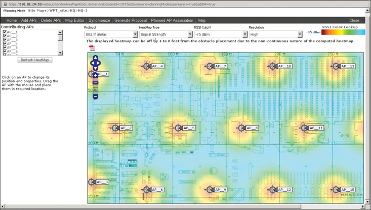
Figure 2-2 Predictive Survey Output in Prime Infrastructure
Note
Before going into Planning mode, you can edit your map to add obstacles (walls and such). Although these obstacles are accounted for when displaying the AP heat map in Planning mode, they are not accounted for when computing the heat map. You can also add these obstacles from within Planning mode by clicking Map Editor.
The goal of Planning mode is to seed your map with APs. It is not intended to be a recommendation on where to position the APs. Once the APs are displayed on the map, you should spend time displaying various levels of cutoff values and moving the APs to locations that logically make sense for the intended floor plan.
If your floor plan is already managed and has APs, you can click Synchronize to take these APs into account in your planning. You can also generate a proposal document with the planned APs by clicking generate Proposal.
Summary
This chapter described the main considerations needed to prepare for an onsite survey and run an offsite survey. More precisely, you have learned the following:
How construction material and obstacles affect your RF signal
How different industries and verticals have specific but common requirements for wireless deployments
How regulations affect the transmission power of your APs, the antenna you are allowed to use, and also how your survey can be conducted
How site survey tools are divided into local install, local LAN server, and cloud categories
How the term site survey is in fact a combination of multiple possible tasks
How to perform a predictive site survey using Cisco Prime Infrastructure
References
For additional information, refer to these resources:
Cisco Campus LAN and Wireless LAN Design Guide: https://www.cisco.com/c/dam/en/us/td/docs/solutions/CVD/Campus/CVD-Campus-LAN-WLAN-Design-Guide-2018JAN.pdf
Cisco Enterprise Mobility 8.1 Design Guide: https://www.cisco.com/c/en/us/td/docs/wireless/controller/8-1/Enterprise-Mobility-8-1-Design-Guide/Enterprise_Mobility_8-1_Deployment_Guide.html
Cisco Wireless LAN Design Guide for High Density Client Environments in Higher Education: https://www.cisco.com/c/en/us/products/collateral/wireless/aironet-1250-series/design_guide_c07-693245.html
Cisco Dorm Deployment Guide: https://www.cisco.com/c/en/us/td/docs/wireless/technology/mesh/8-4/b_Dorm_deployment_guide.html
Cisco Prime Infrastructure: https://www.cisco.com/c/en/us/products/cloud-systems-management/prime-infrastructure/index.html
Cisco Prime Infrastructure Planning mode: https://www.cisco.com/c/en/us/td/docs/net_mgmt/prime/infrastructure/3-2/user/guide/bk_CiscoPrimeInfrastructure_3_2_0_UserGuide/bk_CiscoPrimeInfrastructure_3_2_0_UserGuide_chapter_0111.html
Ekahau Pro: https://www.ekahau.com/products/ekahau-site-survey/overview/
Yagna Predictive WiFi Site Survey: https://www.yagnaiq.com/wifi-site-planner/
Exam Preparation Tasks
As mentioned in the section “How to Use This Book” in the Introduction, you have a few choices for exam preparation: the exercises here, Chapter 18, “Final Preparation,” and the exam simulation questions in the Pearson Test Prep Software Online.
Review All Key Topics
Review the most important topics in this chapter, noted with the Key Topic icon in the outer margin of the page. Table 2-4 lists these key topics and the page numbers on which each is found.
Table 2-4 Key Topics for Chapter 2
Key Topic Element |
Description |
Page Number |
|---|---|---|
Paragraph |
dB and dBm |
26 |
Common obstacles and their attenuation |
27 |
|
5GHz channels in common regulatory domains |
34 |
|
Power limits in common regulatory domains |
36 |
|
List |
The main site survey tools |
39 |
Define Key Terms
Define the following key terms from this chapter and check your answers in the glossary:
Federal Communications Commission (FCC)
European Telecommunication Standards Institute (ETSI)