
Appendix B
Software-Defined Access with Wireless
Campus networks have traditionally been built upon the three-layer architecture of access, distribution, and core. Over time, many large campus networks have added virtualization, employing technologies such as Multiprotocol Label Switching (MPLS), Generic Routing Encapsulation (GRE), and others that allow overlay segmentation of traffic into virtual private networks (VPNs).
Software-Defined Access (SDA) is a Cisco technology that is an evolution of the traditional campus network that delivers intent-based networking (IBN) and central policy control using Software-Defined Networking (SDN) components.
SD-Access is built upon the following three network-centric pillars:
A network fabric: The network fabric is an abstraction of the network itself, supporting programmable overlays and virtualization. The network fabric supports both wired and wireless access and allows it to host multiple logical networks that are segmented from one other and are defined by business intent.
Orchestration: DNA Center is the orchestrator engine of SDA and functions much like an SDN controller, implementing policy and configuration changes in the fabric. DNA Center also incorporates a tool supporting network design and supports real-time network telemetry operations and performance analytics through DNA Assurance. In summary, the role of DNA Center is to orchestrate the network fabric to deliver policy changes and network intent for security, quality of service (QoS), and microsegmentation.
Policy: Identity Services Engine (ISE) is the tool that defines network policy, which organizes how devices and nodes are segmented into virtual networks. While ISE defines the policy, the orchestration of the policy, including segmentation, is implemented in the network fabric by DNA Center. ISE also defines scalable group tags (SGTs) that are used by access devices to segment user traffic as it enters the fabric. SGTs are responsible for enforcing the microsegmentation policy defined by ISE.
Figure B-1 illustrates the three pillars of Cisco SDA.
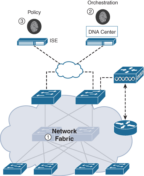
Figure B-1 Core SDA Components
Network fabrics have been around for many years. For example, it is common to see campus networks using GRE or MPLS supporting multiple VPNs. The challenge is that overlay fabrics tend to be complex and require a significant amount of administrator overhead when deploying new virtual networks or implementing security policies for existing ones. Other network fabrics such as DMVPN, FlexVPN, VXLAN, and many others have also been popular; however, they also suffer from the same challenges and limitations as MPLS or GRE. While the fabric implementations just mentioned do not require centralized orchestration, SDA is built up on it. For SDA, the combination of DNA Center as the programmable orchestration engine, ISE as the policy engine, and a new generation of programmable switches makes it a much more flexible and manageable fabric system than anything that has come before.
The network fabric is composed of the following elements (see Figure B-2):
Control plane (CP) node / mapping server: This is the location mapping system that is part of the Location Identifier Separator Protocol (LISP) control plane, managing endpoint identity (EID) to location relationships. Either the CP node can be a dedicated router that provides control plane functions (similar to a route reflector in a BGP deployment) or it can coexist with other fabric network elements (it is preferable to use a dedicated router for this purpose, especially in large or mission-critical SDA deployments). The CP is a critical infrastructure piece of the SDA architecture, so it is recommended to be deployed in a resilient way.
Fabric border nodes: A fabric border node is typically a router that functions at the border between external networks and the SDA fabric, providing routing services to the virtual networks in the fabric. The fabric border node is responsible for internetworking between the internal SDA virtual networks and the networks on the outside of the fabric. The border node can be thought of as an exit point from the SDA virtual networks as they send traffic to outside segments, such as to a firewall, a guest network, or to the Internet.
Fabric edge nodes: A fabric edge node is a device within the fabric that connects non-fabric devices, such as switches, wireless access points (APs), and routers to the SDA fabric. These are the nodes that create the virtual overlay tunnels and virtual networks (VNs) with Virtual eXtensible LAN (VXLAN) and impose the SGTs on fabric-bound traffic. The fabric nodes are similar to border nodes in that they sit on the edge of the fabric, with a key difference being that the networks on both sides of the fabric edge are inside the SDA network. The networks on the non-fabric side are where the virtual networks live. When they enter the fabric, they must go through a fabric edge node where they are encapsulated in VXLAN as they are sent over the SDA core fabric. The fabric edge and border nodes participate in the fabric control plane using LISP.
Extended nodes: These are network elements not directly part of the fabric (they do not participate in LISP and their traffic is not encapsulated in VXLAN) but are connected to the fabric edge nodes. The extended nodes may be managed by DNA Center.
Intermediate nodes: These nodes are inside the core of the SDA fabric and connect to either edge or border nodes. The intermediate nodes simply forward SDA traffic as IP packets, unaware that there are multiple virtual networks involved.
Fabric wireless controller: This is a wireless controller that is fabric-enabled and participates in the SDA control plane (similar to a fabric edge node) but does not process the CAPWAP data plane.
Fabric mode APs: These access points are fabric-enabled. Wireless traffic is VXLAN-encapsulated at the AP, which allows it to be sent into the fabric through an edge node.
Figure B-2 illustrates the various components of the SDA network fabric.
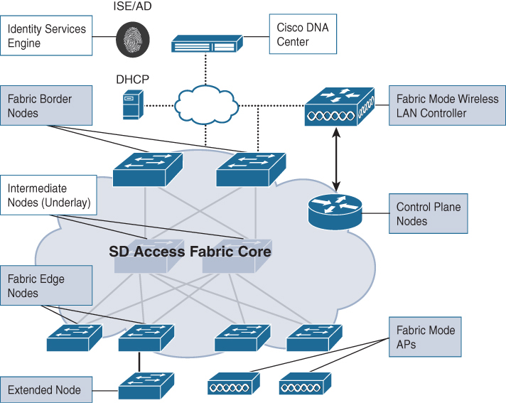
Figure B-2 Cisco SDA Fabric Components
SDA Network Architecture—Underlay and Overlay Networks
The SDA architecture utilizes fabric technology that supports programmable virtual networks (overlay networks) that run on a physical network (an underlay network).
The fabric underlay network is defined by the physical nodes, including switches, routers, and wireless access points that are used in the SDA network. All network elements of the underlay must have IP connectivity and use an IP routing protocol. In the case of SDA, IS-IS is the underlay routing protocol of choice. While the underlay network is not likely to use the traditional access, distribution, core model, it must use a well-designed Layer 3 foundation that delivers robust performance, scalability, and high availability. In SDA, the underlay switches support the transport of physical endpoints connected to extended nodes and beyond. The end-user subnets and endpoints are not part of the underlay fabric network core routing table, as these subnets are routed through the overlay (this is similar to MPLS, where the backbone P and PE routers do not carry virtual network subnets—these are part of the VPN routing tables in the overlay). In SDA, the user subnets are part of a programmable overlay network that may run at Layer 2 or Layer 3. SDA supports IPv4 in the underlay network and IPv4 and/or IPv6 in overlay networks.
An overlay network is created on top of the underlay to create one or more virtualized and segmented networks. Due to the software-defined nature of overlays, it is possible to connect them in very flexible ways without the constraints of physical connectivity. For example, if you wanted to connect two accounting offices in a campus network that were physically separated, it would be possible to connect these two sites through a fabric overlay and make them appear as if they were part of the same physical network. In this way, network overlays offer natural segmentation that is not possible on physical networks. They also provide an easy way to enforce security policies because the overlay can be programmed to have a single physical exit point (the fabric border node), and thus one firewall can be used to protect the networks behind it, wherever they may be located.
Data plane traffic and control plane signaling (routing updates) for the overlays are independent of each other within each virtualized network. The SDA fabric implements virtualization of the overlays by encapsulating user traffic in VXLAN tunnels that connect through the underlay. These tunnels are sourced and terminated at the boundaries of the fabric (the fabric edge and border nodes).
The fabric is designed to carry multiple overlays at the same time supporting multitenancy and segmentation between networks. For example, one overlay may be created for IoT devices, such as digital ceiling lights, whereas another may be created for contractors who are working at the office. Through the fabric, the devices and subnets used on each overlay are completely separated from each other, no matter where the devices are physically located.
At the fabric edge, each overlay network appears as a virtual routing and forwarding (VRF) instance, similar to MPLS. In order to preserve extension of the overlay separation outside of the network, VRF-Lite is used (VRFs are used in combination with 802.1q tunnels between non-fabric switching nodes to securely extend the fabric). Overlays also support the flexibility of Layer 2 or Layer 3, depending on the requirement of the overlay.
When Layer 2 is used across overlays, an important point is that SDA supports MAC learning without the use of flooding. Flooding on traditional Layer 2 networks can easily overwhelm resources on a router and cause performance issues, thus limiting the feasible size of the network; however, with SDA, MAC learning removes this restriction and supports the creation of large Layer 2 domains.
Figure B-3 illustrates a comparison between underlay and overlay networks.

Figure B-3 Comparing the Fabric Underlay and Overlay
Fabric Control, Data, and Security Planes
The function of SDA incorporates three separate “planes”: the control, data, and security planes. These are summarized as follows:
Control plane: Based on LISP, functions in the underlay
Data plane: Based on VXLAN, encapsulates the overlay traffic
Security plane: Utilizes SGTs to securely identify users and devices and put them into the correct overlay
The function of mapping and resolving endpoint addresses requires a control plane protocol. For the control plane, SDA uses LISP. LISP brings the advantage of routing based not only on the IP or MAC address as the endpoint identifier (EID) of a device but also routing based on an additional IP address that it provides as a routing locator (RLOC) to represent the network location of that device. This has the advantage of allowing the IP addresses of a device to move from one location to another location without having to readdress through DHCP. In this way, the EID and RLOC work very similarly to DNS—instead of finding exactly where a node is by looking up its IP address in a routing table, the RLOC allows LISP to check with the control plane node (the LISP mapping server) to find the current location of an IP address, and it reroutes the overlay tunnel to the EID of this location, allowing the fabric to follow a user wherever a device may go. Note that the control plane (CP) is key in this capability—the CP is signaled in real time as a node moves, providing updated routing information via LISP so connectivity can be maintained. In this way, the CP is the authoritative trust point to find a node—any user who wants to send a packet to another node inside the fabric will use the CP to find the node’s current location, similar to how a DNS server resolves a host name to find a current IP address for a certain domain.
Thus, the EID and RLOC combination provides the necessary information for traffic forwarding, even if an endpoint continues to use the same IP address as it moves to a different network location. Simultaneously, the decoupling of the endpoint identity from its location allows addresses in the same IP subnet to be available behind multiple Layer 3 gateways, versus a one-to-one coupling of IP subnets with a network gateway, as is used in a traditional network. Figure B-4 illustrates how the LISP control plane functions in an SDA network.
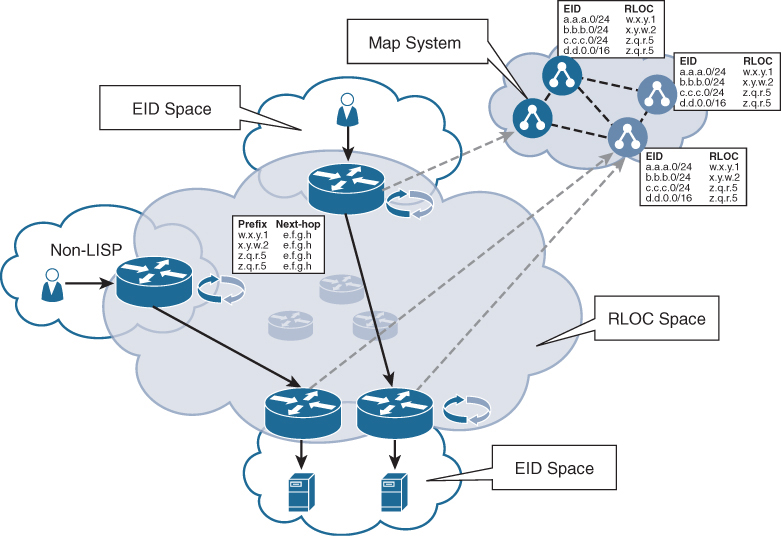
Figure B-4 The VXLAN-GPE Header
The SDA overlay encapsulates traffic using VXLAN. VXLAN encapsulates complete Layer 2 frames for transport across the underlay with each overlay network identified by a VXLAN network identifier (VNI). The VXLAN Generic Protocol Extension (GPE) header also carries the SGTs that are defined by ISE and allow for microsegmentation of traffic. Figure B-5 illustrates the entire VXLAN header format, including the RLOC source and destination address.

Figure B-5 The VXLAN-GPE Header
As noted in Figure B-5, the 16-bit SGT is embedded directly into the VXLAN header. The SGT is assigned from ISE during the authentication of the user or the device during the onboarding phase to indicate the security policy. The SGT is used to identify what virtual network (VN) overlay the traffic should be assigned to. The SGTs can also be used at firewalls for filtering purposes.
Wireless Capabilities of SDA
SDA supports two wireless deployment models:
Over the top (OTT) model: A traditional CAPWAP deployment connected on top of a fabric wired network. The SDA fabric transports the CAPWAP control and data plane traffic to the wireless controller.
Fully integrated SDA model: The wireless network is fully integrated to the fabric and participates in overlays, allowing different WLANs to be part of different VNs. In this model, the wireless controller only manages the CAPWAP control plane, and the CAPWAP data plane does not come to the controller.
In the OTT model, the SDA fabric is simply a transport network for wireless traffic—a model often deployed in migrations. In this model, the AP works very similarly to classic Local mode, where both the CAPWAP control and data planes terminate on the controller, meaning the controller does not directly participate in the fabric. This model is often used when wired switches are first migrated to the SDA fabric but the wireless network is not yet ready for full fabric overlay integration. Figure B-6 illustrates the OTT model.
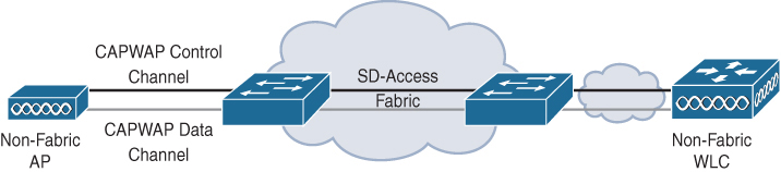
Figure B-6 The OTT Wireless Integration Option
The second deployment option is to fully integrate wireless into the SDA fabric, extending the SDA benefits to include wireless users where endpoints and users are part of VN overlays. There are significant advantages to be gained by integrating wireless into the SDA fabric, such as allowing wired and wireless networks to be part of the same VN, as well as unification of the security policy. Figure B-7 illustrates a fully integrated wireless fabric.

Figure B-7 Wireless Fully Integrated SDA Fabric
Fully integrated SDA involves the wireless controller using the CAPWAP control plane to manage APs, while the data plane does not go to the controller. In this case, the wireless data plane is handled similarly to wired switches—each AP encapsulates data in VXLAN and sends it to a fabric edge node where it is then sent across the fabric to another edge node. In this mode, the wireless controllers must be configured as fabric controllers—a modification from their normal operation. Fabric-enabled controllers communicate with the fabric control plane, registering Layer 2 client MAC addresses, SGTs, and Layer 2 Virtual Network Identifier (VNI) information. The APs are responsible for communication with wireless endpoints, and in the wired domain, the APs assist the VXLAN data plane by encapsulating and de-encapsulating traffic.
From a CAPWAP control perspective, the wireless LAN controllers manage and control the fabric mode APs in the same way as APs running in classic Local or FlexConnect mode. The controller continues to perform Radio Resource Management (RRM), mobility control, authentication of clients, and other functions that use the CAPWAP control function. A significant difference is that wireless client data from fabric-enabled SSIDs does not use CAPWAP encapsulation and forwarding from the APs to the controller. Instead, communication from wireless clients is VXLAN-encapsulated by fabric-attached APs and uses the LISP control plane to communicate with other fabric endpoints or outside of the fabric. This difference enables the wireless network to take advantage of the integrated policy elements of SDA, such as using SGTs. When this is deployed, traffic forwarding takes the optimum path through the SD-Access fabric to the destination with consistent policy, regardless of wired or wireless endpoint connectivity.
The SDA control plane inherently supports roaming by updating the host-tracking database on the control plane node (the mapping server), updating any changes to a wireless client’s EID-to-RLOC mapping. Although fabric mode APs are used for VXLAN traffic encapsulation of wireless traffic, they are not considered edge nodes. Instead, APs are connected to edge node switches using VXLAN encapsulation and rely on those switches to provide fabric services. APs can be physically connected to either an edge or extended node switch.
Integrating wireless into the fabric leads to several advantages for the wireless network, including addressing simplification, mobility with stretched subnets across physical locations, and microsegmentation with centralized policy that is consistent across both of the wired and wireless domains. Another significant advantage of wireless fabric integration is that it enables the controller to shed data plane forwarding duties while continuing to function as the centralized services and control plane for the wireless network. In this way, wireless controller scalability is actually increased because it no longer needs to process data plane traffic, similar to the FlexConnect model.