
Chapter 6. Data Center Network Management and Monitoring
Managing a data center infrastructure requires extraordinary uptime and reliability. Network monitoring, operation, and lifecycle management are required to sustain high uptimes and improve network performance.
The Cisco Nexus NX-OS provides best-in-class high availability, scalability, security, and management, allowing network engineers to deploy a high-performance data center infrastructure network. Cisco Nexus supports management and monitoring protocols such as syslog, SNMP, NetFlow, and Switched Port Analyzer (SPAN).
This chapter discusses the software management and infrastructure monitoring aspects of the Cisco Nexus family switches relevant to the certification exam. It is assumed that you are familiar with the Cisco Nexus product family.
This chapter discusses the following key topics:
• Cisco Nexus NX-OS Software installation, Updates, and Their Impacts: This section discusses the Cisco Nexus NX-OS software installation, software disruptive and nondisruptive upgrade and downgrade procedures, and the erasable programmable logical devices (EPLD) upgrade procedure.
• Network Configuration Management: This section discusses the Nexus NX-OS configuration backup and restore operations and how to set a rollback point procedure.
• Network Infrastructure Monitoring: This section discusses various system management features used to monitor and manage a switch using the Cisco Nexus NX-OS software, including System Messages, NTP, SNMP, Call Home, SPAN, and NetFlow features.
• Streaming Telemetry: This section discusses the Cisco Nexus streaming telemetry that exports system monitoring data in JavaScript Object Notation (JSON) or Google Protocol Buffers (GPB) format in an efficient way. It also includes a configuration example.
• Network Assurance Concepts: This section discusses the Cisco Network Assurance Engine solution.
“Do I Know This Already?” Quiz
The “Do I Know This Already?” quiz enables you to assess whether you should read this entire chapter thoroughly or jump to the “Exam Preparation Tasks” section. If you are in doubt about your answers to these questions or your own assessment of your knowledge of the topics, read the entire chapter. Table 6-1 lists the major headings in this chapter and their corresponding “Do I Know This Already?” quiz questions. You can find the answers in Appendix A, “Answers to the ‘Do I Know This Already?’ Quizzes.”
Table 6-1 “Do I Know This Already?” Section-to-Question Mapping”

Caution
The goal of self-assessment is to gauge your mastery of the topics in this chapter. If you do not know the answer to a question or are only partially sure of the answer, you should mark that question as wrong for purposes of the self-assessment. Giving yourself credit for an answer you correctly guess skews your self-assessment results and might provide you with a false sense of security.
1. Which statements are true regarding the Cisco Nexus setup utility? (Choose two answers.)
a. After bootup, the setup utility will start if there is a config file saved in NVRAM.
b. After bootup, the setup utility will start if there is no config file saved in NVRAM.
c. The config utility is a dialog with steps that help you configure the Nexus switch.
d. The config utility is a dialog with steps that help you switch the initial configuration only.
2. In which programming languages does Cisco offer configuration scripts for POAP? (Choose two answers.)
a. JSON
b. Python
c. TCL
d. Perl
3. When is a Nexus switch system checkpoint generated? (Choose two answers.)
a. When a license expires
b. When the interface config changes
c. When a specific feature is disabled
d. When the Local admin password changes
4. Which protocol and port are used in SNMP polling by default?
a. TCP 161
b. UDP 161
c. TCP 163
d. UDP 163
5. The Cisco Nexus switch can act as an NTP stratum 1 server.
a. True
b. False
6. Cisco NX-OS streaming telemetry allows you to push data off the device to a server endpoint as or using ____________. (Choose two answers.)
a. JavaScript Object Notation (JSON)
b. Google Protocol Buffers (GPB)
c. XML
d. TCL
7. With the Cisco Network Assurance Engine, you can ____________. (Choose two answers.)
a. Predict the impact of changes
b. Prevent network configuration changes
c. Prevent a network security breach
d. Verify networkwide behavior
Foundation Topics
Cisco Nexus NX-OS Software Installation, Updates, and Their Impacts
Cisco Nexus devices ship with the Cisco NX-OS operating system. NX-OS has the following images:
• BIOS and loader images combined in one file
• Kickstart image
• System image that includes a BIOS image that can be upgraded
A Nexus switch requires a basic setup to enable management. Cisco NX-OS offers a startup setup utility that guides you through a basic (also called a startup) configuration of the system. The setup utility allows you to configure only enough connectivity for system management.
Before creating a network management configuration and connecting the switch to the network, you must create a local management connection through a console terminal and configure the switch with basic management configurations.
You can also use the console to perform the following functions:
• Configure the switch using the command-line interface (CLI).
• Monitor network statistics and errors.
• Configure Simple Network Management Protocol (SNMP) agent parameters.
• Download software updates.
A console local management connection is made between the asynchronous serial port on each Cisco Nexus switch and a console device capable of asynchronous transmission, such as a computer terminal or a laptop, as shown in Figure 6-1. Before you can connect the console port to a computer terminal, make sure that the computer terminal supports VT100 terminal emulation. The terminal emulation software makes communication between the switch and computer possible during setup and configuration. Figure 6-1 shows a laptop connection to a switch console port.
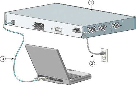
Figure 6-1 Cisco Nexus Console Management Connection
To connect the Cisco Nexus Series switch to a computer terminal, you need to match the following default port characteristics:
9600 baud
8 data bits
1 stop bit
No parity
When the switch boots, the golden BIOS validates the checksum of the upgradeable BIOS. If the checksum is valid, control is transferred to an upgradeable BIOS image. The upgradeable BIOS launches the kickstart image, which then launches the system image. If the checksum of the upgradeable BIOS is not valid, the golden BIOS launches the kickstart image, which then launches the system image.
You can force the switch to bypass the upgradeable BIOS and use the golden BIOS instead. If you press Ctrl+Shift+6 within two seconds after power is supplied to the switch, the golden BIOS is used to launch the kickstart image, even if the checksum of the upgradeable BIOS is valid.
Before the boot sequence starts, the BIOS performs internal tests on the switch. If the tests fail, the loader does not gain control. Instead, the BIOS image retains control and prints a message to the console at 9600 baud every 30 seconds to indicate a failure.
Figure 6-2 shows the normal and recovery boot sequence.
![]()
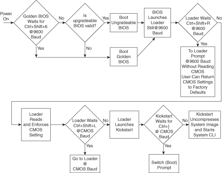
Figure 6-2 Nexus NX-OS Boot Sequence
When a boot is successful, you can use the setup utility to build an initial configuration file using the System Configuration dialog. The setup starts automatically when a device has no configuration file in NVRAM. The dialog guides you through the initial configuration. After the file is created, you can use the command-line interface to perform additional configuration.
You can press Ctrl+C at any prompt to skip the remaining configuration options and proceed with what has been configured up to that point, except for the Admin password. If you want to skip answers to any questions, press Enter. If a default answer is not available (for example, the device host name), the device uses what was previously configured and skips to the next question.
![]()
To configure basic management of the Cisco NX-OS device using the setup utility, follow these steps:
Step 1. Power on the device.
Step 2. Enable or disable password-strength checking.
---- System Admin Account Setup ----
Do you want to enforce secure password standard (yes/no) [y]: y
A strong password has the following characteristics:
• Is at least eight characters long
• Does not contain many consecutive characters (such as “abcd”)
• Does not contain many repeating characters (such as “aaabbb”)
• Does not contain dictionary words
• Does not contain proper names
• Contains both uppercase and lowercase characters
• Contains numbers
Step 3 Enter the new password for the admin account.
Enter the password for “admin”: <password>
Confirm the password for “admin”: <password>
---- Basic System Configuration Dialog ----
This setup utility guides you through the basic configuration of the system. Setup configures only enough connectivity for management of the system.
Be sure to register Cisco Nexus family devices promptly with your supplier. Failure to register may affect response times for initial service calls. Nexus devices must be registered to receive entitled support services.
Press Enter at any time to skip a dialog. Press Ctrl+C at any time to skip the remaining dialogs.
Step 4. Enter the setup mode by entering yes.
Would you like to enter the basic configuration dialog (yes/no): yes
Step 5. Create additional accounts by entering yes (no is the default).
Create another login account (yes/no) [n]: yes
Enter the user login ID.
Enter the User login Id : user_login
Note
Usernames must begin with an alphanumeric character and can contain only these special characters: (+ = . _ -). The # and ! symbols are not supported. If the username contains characters that are not allowed, the specified user is unable to log in.
Enter the password for “user1”: user_password
Confirm the password for “user1”: user_password
Enter the user role (network-operator|network-you) [network-operator]: default_user_role
Step 6. Configure an SNMP community string by entering yes.
Configure read-only SNMP community string (yes/no) [n]: yes
SNMP community string: snmp_community_string
Enter the switch name: switch_name
Step 7. Configure out-of-band management by entering yes. You can then enter the Mgmt0 IPv4 address and subnet mask.
Continue with Out-of-band (mgmt0) management configuration? [yes/no]: yes
Mgmt0 IPv4 address: Mgmt0_ip_address
Mgmt0 IPv4 netmask: Mgmt0_subnet_mask
Step 8. Configure the IPv4 default gateway (recommended) by entering yes. You can then enter its IP address.
Configure the default-gateway: (yes/no) [y]: yes
IPv4 address of the default-gateway: default_gateway
Step 9. Configure advanced IP options such as the static routes, default network, DNS, and domain name by entering yes.
Configure Advanced IP options (yes/no)? [n]: yes
Step 10. Configure a static route (recommended) by entering yes. You can then enter its destination prefix, destination prefix mask, and next hop IP address.
Configure static route: (yes/no) [y]: yes
Destination prefix: dest_prefix
Destination prefix mask: dest_mask
Next hop ip address: next_hop_address
Step 11. Configure the default network (recommended) by entering yes. You can then enter its IPv4 address.
Note
The default network IPv4 address is the same as the destination prefix in the static route configuration.
Configure the default network: (yes/no) [y]: yes
Default network IP address [dest_prefix]: dest_prefix
Step 12. Configure the DNS IPv4 address by entering yes. You can then enter the address.
Configure the DNS IP address? (yes/no) [y]: yes
DNS IP address: ipv4_address
Step 13. Configure the default domain name by entering yes. You can then enter the name.
Configure the DNS IP address? (yes/no) [y]: yes
DNS IP address: ipv4_address
Step 14. Enable the Telnet service by entering yes.
Enable the telnet service? (yes/no) [y]: yes
Step 15. Enable the SSH service by entering yes. You can then enter the key type and number of key bits.
Enable the ssh service? (yes/no) [y]: yes
Type of ssh key you would like to generate (dsa/rsa) : key_type
Number of key bits <768-2048> : number_of_bits
Step 16. Configure the NTP server by entering yes. You can then enter its IP address.
Configure NTP server? (yes/no) [n]: yes
NTP server IP address: ntp_server_IP_address
Step 17. Specify a default interface layer (L2 for Layer 2 or L3 for Layer 3).
Configure default interface layer (L3/L2) [L3]: interface_layer
Step 18. Enter the default switchport interface state (shutdown or no shutdown). A shutdown interface is in an administratively down state.
Configure default switchport interface state (shut/noshut) [shut]: default_state
Step 19. Enter the best practices profile for Control Plane Policing (CoPP).
Configure best practices CoPP profile (strict/moderate/lenient/none) [strict]: policy
The system now summarizes the complete configuration and asks if you want to edit it.
Step 20. Continue to the next step by entering no. If you enter yes, the setup utility returns to the beginning of the setup and repeats each step.
Would you like to edit the configuration? (yes/no) [y]: no
Step 21. Use and save this configuration by entering yes.
Use this configuration and save it? (yes/no) [y]: yes
Note
If you do not save the configuration at this point, none of your changes will be part of the configuration the next time that the device reboots. Enter yes to save the new configuration to ensure that the boot variables for the NX-OS image are also automatically configured.
PowerOn Auto Provisioning (POAP)
PowerOn Auto Provisioning (POAP) automates the process of upgrading software images and installing configuration files on Cisco Nexus switches that are being deployed in the network for the first time.
When a Cisco Nexus Series switch with the POAP feature boots and does not find the startup configuration, the switch enters POAP mode, locates a DHCP server, and bootstraps itself with its interface IP address, gateway, and DNS server IP addresses. The switch also obtains the IP address of a TFTP server or the URL of an HTTP server and downloads a configuration script that enables the switch to download and install the appropriate software image and configuration file.
If a universal serial bus (USB) device that contains the required installation files is not available, POAP requires many services to support POAP, as shown in Figure 6-3. The network infrastructure requirements are as follows:
• A DHCP server to bootstrap the interface IP address, gateway address, and Domain Name System (DNS) server
• A TFTP server that contains the configuration script used to automate the software image installation and configuration process
• One or more servers that contain the desired software images and configuration files

Figure 6-3 POAP Network Infrastructure
The reference script supplied by Cisco supports the following functionality:
• Retrieves the switch-specific identifier—for example, the serial number.
• Downloads the software image (system and kickstart images) if the files do not already exist on the switch. The software image is installed on the switch and is used at the next reboot.
• Schedules the downloaded configuration to be applied at the next switch reboot.
• Stores the configuration as the startup configuration.
Cisco offers sample configuration scripts that were developed using the Python programming language and Tool command language (Tcl). You can customize one of these scripts to meet the requirements of your network environment.
The POAP process has the following phases:
1. Power up
2. USB discovery
3. DHCP discovery
4. Script execution
5. Post-installation reload
Within these phases, other process and decision points occur. Figure 6-4 shows a flow diagram of the POAP process.
![]()
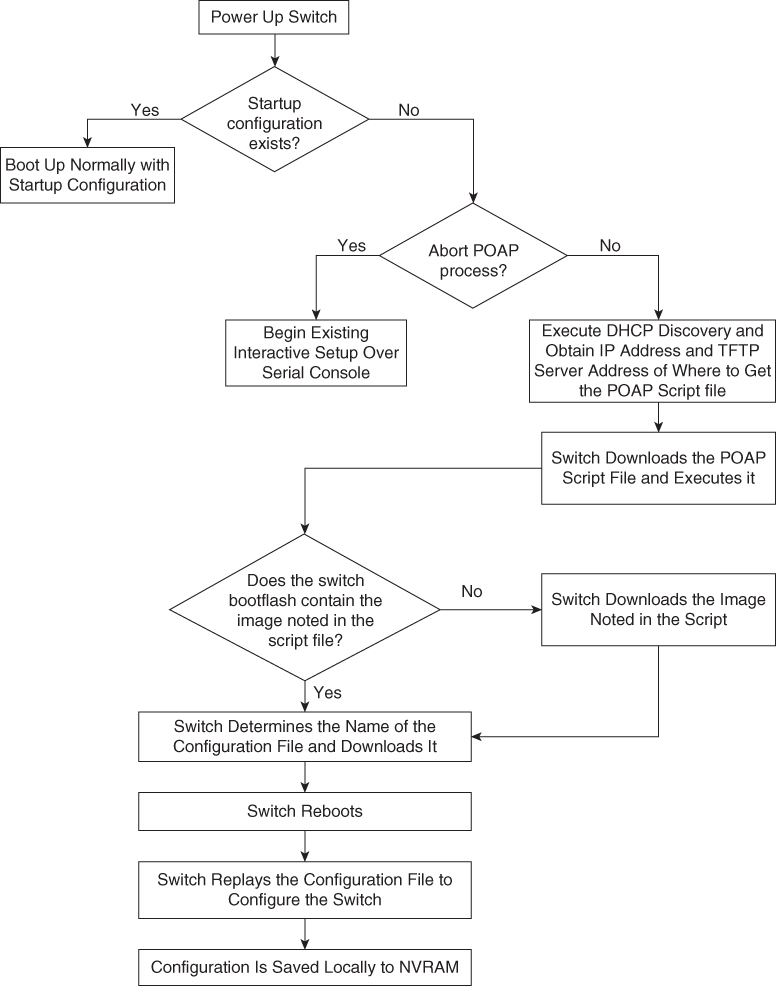
Figure 6-4 POAP Process Flow Diagram
To set up the network environment to use POAP, follow these steps:
Step 1. Modify the basic configuration script provided by Cisco or create your own script.
The sample POAP script (poap.py) in Example 6-1 includes the personality feature.
Example 6-1 Cisco poap.py Script Example
#md5sum=“b00a7fffb305d13a1e02cd0d342afca3”
# The above is the (embedded) md5sum of this file taken without this line, # can be # created this way:
# f=poap.py ; cat $f | sed ‘/^#md5sum/d’ > $f.md5 ; sed -i “s/^#md5sum=.*/#md5sum=$(md5sum $f.md5 | sed ‘s/ .*//’)/” $f # This way this script’s integrity can be checked in case you do not trust # tftp’s ip checksum. This integrity check is done by /isan/bin/poap.bin).
# The integrity of the files downloaded later (images, config) is checked # by downloading the corresponding file with the .md5 extension and is # done by this script itself.

from poap.personality import POAPPersonality import os

# Location to download system image files, checksums, etc.
download_path = “/var/lib/tftpboot”
# The path to the personality tarball used for restoration personality_tarball = “/var/lib/tftpboot/foo.tar”
# The protocol to use to download images/config protocol = “scp”
# The username to download images, the personality tarball, and the # patches and RPMs during restoration username = “root”
# The password for the above username
password = “C1$c04321”
# The hostname or IP address of the file server server = “1.1.1.1”

# The VRF to use for downloading and restoration vrf = “default”
if os.environ.has_key(‘POAP_VRF’):
    vrf = os.environ[‘POAP_VRF’]

# Initialize housekeeping stuff (logs, temp dirs, etc.) p = POAPPersonality(download_path, personality_tarball, protocol, username, password, server, vrf)

p.get_personality()
p.apply_personality()

sys.exit(0)
Step 2. (Optional) Put the POAP configuration script and any other desired software image and switch configuration files on a USB device that is accessible to the switch.
Step 3. Deploy a DHCP server and configure it with the interface, gateway, and TFTP server IP addresses and a boot file with the path and name of the configuration script file. (This information is provided to the switch when it first boots.)
Note
You do not need to deploy a DHCP server if all software image and switch configuration files are on the USB device.
Step 4. Deploy a TFTP server to host the configuration script.
Step 5. Deploy one or more servers to host the software images and configuration files.
Step 6. Power on the switch.
If no configuration file is found, the switch boots in POAP mode and displays a prompt that asks if you want to abort POAP and continue with a normal setup.
No entry is required to continue to boot in POAP mode.
Step 7. (Optional) If you want to exit POAP mode and enter the normal interactive setup script, enter y (yes).
The switch boots, and the POAP process begins.
Data Center Infrastructure Software Lifecycle Management
The Cisco NX-OS software-release methodology preserves the integrity, stability, and quality of mission-critical networks. The primary attributes of the release methodology include the following:
• Major releases introduce significant new features, functions, and platforms.
• Minor releases enhance the features and functions of an existing major release.
• Maintenance releases address product defects in a minor release.
If you want to improve data center security and reliability, installing regular NX-OS upgrades is a good exercise. Apart from having new features, defects, and vulnerabilities, fixes are more stable from a protocol perspective.
Cisco NX-OS supports normal upgrades/downgrades, nondisruptive upgrades (ISSU), Software Maintenance Updates (SMUs), and electronic programmable logic device upgrades (EPLDs) for Nexus modular switches (Nexus 7000/9500).
![]()
Nexus Software Maintenance Upgrade
A Software Maintenance Upgrade, or SMU, is a package file that contains patches or fixes for a specific defect. SMUs are created to respond to immediate issues and do not include new features. Typically, SMUs do not have a large impact on device operations. SMU versions are synchronized to the package’s major, minor, and maintenance versions they upgrade.
The effect of an SMU depends on its type:
• Process restart SMU: Causes a process or group of processes to restart on activation.
• Reload SMU: Causes a parallel reload of supervisors and line cards.
SMUs are not an alternative to maintenance releases. They provide a quick resolution of immediate issues. All defects fixed by SMUs are integrated into the maintenance releases.
• SMUs in NX-OS build upon years of experience in Cisco IOS XR.
• SMUs simplify customer operations for defect resolution and code qualification.
• SMUs better utilize the software HA capabilities of NX-OS.
• SMUs provide a common cross-platform experience (Nexus 9000/Nexus 7000/Nexus 6000/Nexus 5000).
SMU types include the following:
• Restart: Restarts an affected process. The process is restarted in all virtual device contexts (VDCs) where running.
• In-Service Software Upgrade (ISSU) SMU:
• Dual Supervisor > ISSU
• Single Supervisor > Reload
Patching is for operationally impacting bugs without a workaround:
• You cannot patch the next release.
• For the Nexus 7000 Series, patching is done in default/admin VDC and applies to all VDCs; patching is not available per VDC.
• ISSUs work with all or a subset of patches applied.
• You don’t need to apply all patches.
• Some SMUs may have only a single fix, whereas others may have multiple packages.
• SMUs are supported by the Cisco Technical Assistance Center (TAC).
• SMUs are synced to standby supervisor.
• On a Supervisor replacement, patches are synchronized.
• SMUs are not for feature implementation. An SMU cannot change the configuration.
The steps to download and apply a specific SMU are as follows:
Step 1. Download the appropriate SMU for your device from Cisco.com.
Step 2. Copy the package file from the TFTP or FTP or SFTP server to the bootflash:
switch# copy tftp://10.1.1.1/images/n7700-s2-dk9.7.2.0.D1.1.CSCuo07721.bin bootflash:
Step 3. Display the package files that are available to be added under flash:
Step 4. Activate a package that was added to the device. The SMU packages remain inactive until activated.
switch# install activate n7700-s2- dk9.7.2.0.D1.1.CSCuo07721.bin
Install operation 158 completed successfully at Tue Jun 11 19:09:33 2019
Step 5. Commit the current set of packages so that these packages are used if the device is restarted.
switch# install commit n7700-s2-dk9.7.2.0.D1.1.CSCuo07721.bin
Install operation 2 completed successfully at Tue Jun 11 20:20:46 2019

switch# show install committed
Boot Images:
      Kickstart Image: bootflash:/n7700-s2-kickstart.7.2.0.D1.1.bin
      System Image: bootflash:/ n7700-s2-dk9.7.2.0.D1.1.bin

Committed Packages:
      n7700-s2-dk9.7.2.0.D1.1.CSCuo07721.bin
Step 6. Deactivate and uninstall the package.
switch# install deactivate n7700-s2-dk9.7.2.0.D1.1.CSCuo07721.bin
Install operation 3 completed successfully at Tue Jun 9 01:20:36 2019

switch# show install inactive
Inactive Packages: n7700-s2-dk9.7.2.0.D1.1.CSCuo07721.bin

switch# install commit
Install operation 4 completed successfully at Tue Jun 9 01:20:46 2019

switch# install remove n7700-s2-dk9.7.2.0.D1.1.CSCuo07721.bin
Proceed with removing n7700-s2-dk9.7.2.0.D1.1.CSCuo07721.bin? (y/n)? [n] y
Install operation 5 completed successfully at Tue Jun 9 01:20:57 2019
![]()
Programmable Logical Devices Upgrade
Cisco Nexus modular switches (Nexus 7000 and 9500) contain several programmable logical devices (PLDs) that provide hardware functionalities in all modules. Cisco provides EPLD image upgrades to enhance hardware functionality or to resolve known issues for modular switches only. PLDs include EPLDs, field programmable gate arrays (FPGAs), and complex programmable logic devices (CPLDs), but they do not include application-specific integrated circuits (ASICs). In this chapter, the term EPLD is used for FPGAs and CPLDs.
The advantage of having EPLDs for some module functions is that when you need to upgrade those functions, you just upgrade their software images instead of replacing their hardware.
Note
EPLD image upgrades for a line card disrupt the traffic going through the module because the module must power down briefly during the upgrade. The system performs EPLD upgrades on one module at a time, so at any one time the upgrade disrupts only the traffic going through one module.
EPLD image updates are not mandatory unless otherwise specified. The EPLD image upgrades are independent from the Cisco in-service software upgrade (ISSU) process, which upgrades the system image with no impact on the network environment.
When new EPLD images are available, the upgrades are always recommended if your network environment allows for a maintenance period in which some level of traffic disruption is acceptable. If such a disruption is not acceptable, then consider postponing the upgrade until a better time.
Note
The EPLD upgrade operation is a disruptive operation. Execute this operation only at a programmed maintenance time. The system ISSU upgrade is a nondisruptive upgrade.
Note
Do not perform an EPLD upgrade during an ISSU system upgrade.
To verify whether an EPLD is required, download and apply the EPLD as follows:
Step 1. Determine whether you need to upgrade an EPLD image or not and determine the upgrade impact.
switch# show install all impact epld bootflash:n7000-s1-epld.5.1.1.img

Compatibility check:
Module  Type    Upgradable        Impact       Reason

------  ----   ----------         ----------   ------
1       LC           Yes           disruptive   Module Upgradable
2       LC           Yes           disruptive   Module Upgradable
4       LC           No            none         Module is not Online
5       SUP          Yes           disruptive   Module Upgradable
7       LC           Yes           disruptive   Module Upgradable
8       LC           Yes           disruptive   Module Upgradable
9       LC           Yes           disruptive   Module Upgradable
10      LC           Yes           disruptive   Module Upgradable
1       Xbar         Yes           disruptive   Module Upgradable
2       Xbar         Yes           disruptive   Module Upgradable
3       Xbar         Yes           disruptive   Module Upgradable
1       FAN          Yes           disruptive   Module Upgradable
2       FAN          Yes           disruptive   Module Upgradable
3       FAN          Yes           disruptive   Module Upgradable
4       FAN          Yes           disruptive   Module Upgradable

Retrieving EPLD versions... Please wait.
Images will be upgraded according to following table:

Module  Type     EPLD         Running-Version   New-Version  g-Required
------  ---- ------------- --------------    -----------  ------------
   1    LC Power Manager       4.008            4.008               No
   1    LC IO                  1.015            1.016               Yes
   1    LC Forwarding Engine   1.006            1.006               No
   1    LC FE Bridge(1)        186.005          186.006             Yes
   1    LC FE Bridge(2)        186.005          186.006             Yes
   1    LC Linksec Engine(1)   2.006            2.006               No
   1    LC Linksec Engine(2)   2.006            2.006               No
   1    LC Linksec Engine(3)   2.006            2.006               No
   1    LC Linksec Engine(4)   2.006            2.006               No
   1    LC Linksec Engine(5)   2.006            2.006               No
   1    LC Linksec Engine(6)   2.006            2.006               No
   1    LC Linksec Engine(7)   2.006            2.006               No
Step 2. Download the EPDL image from Cisco.com.
Step 3. Verify the EPLD upgrade version.
switch# show version module 7 epld

EPLD Device Version
-----------------------------------------
Power Manager 4.008
IO 1.016
Forwarding Engine 1.006
FE Bridge(1) 186.008 << OK!
FE Bridge(2) 186.008 << OK!
Linksec Engine(1) 2.007
Linksec Engine(2) 2.007
Linksec Engine(3) 2.007
Linksec Engine(4) 2.007
Step 4. Upgrade the EPLD for a specific module.
install module 1 epld bootflash:n7000-s1-epld.5.1.1.img

Retrieving EPLD versions... Please wait.

Images will be upgraded according to following table:

Module Type  EPLD            Running-Version New-Version Upg-Required------   ----  -------------  ---------------  ----------- -----------
1       LC    Power Manager     4.008         4.008          No
1       LC    IO                1.015         1.016          Yes
1       LC    Forwarding Engine 1.006         1.006          No
1       LC    FE Bridge(1)      186.005       186.006        Yes
1       LC    FE Bridge(2)      186.005       186.006        Yes
1       LC    Linksec Engine(1) 2.006         2.006          No
1       LC    Linksec Engine(2) 2.006         2.006          No
1       LC    Linksec Engine(3) 2.006         2.006          No
1       LC    Linksec Engine(4) 2.006         2.006          No
1       LC    Linksec Engine(5) 2.006         2.006          No
1       LC    Linksec Engine(6) 2.006         2.006          No
1       LC    Linksec Engine(7) 2.006         2.006          No
1       LC    Linksec Engine(8)  2.006        2.006          No
Module 1 will be powered down.
Do you want to continue? (yes/no) [n]: y
![]()
Graceful Insertion and Removal
Starting with Cisco NX-OS Software Release 7.2, you can use Graceful Insertion and Removal (GIR), or maintenance mode, to isolate a switch from the network to perform an upgrade or downgrade the switch with little service disruption.
You can use GIR mode to simplify the maintenance process. Currently, during maintenance, windows for module installation, cabling, and erasable programmable logic device (EPLD) upgrades, you need to isolate the switch using a series of commands and scripts, which is a cumbersome process. GIR mode provides an easy method for isolating a switch for maintenance windows and then bringing it back into service. You can configure GIR mode for each VDC on Cisco Nexus 7000 Series platform switches, using the existing configuration profile foundation in NX-OS.
The following protocols are currently supported in GIR mode:
• Border Gateway Protocol Version 4 (BGPv4)
• BGP Version 6 (BGPv6)
• Multiprotocol BGP (MP-BGP) address families (Virtual Private Network Version 4 [VPNv4], VPNv6, and Layer 2 VPN [L2VPN] Ethernet VPN [EVPN]
• Enhanced Interior Gateway Routing Protocol (EIGRP)
• Enhanced Interior Gateway Routing Protocol Version 6 (EIGRPv6)
• Intermediate System-to-Intermediate System (ISIS)
• Open Shortest Path First (OSPF)
• Open Shortest Path First Version 3 (OSPFv3)
• Virtual Port Channel (vPC and vPC+)
• Cisco FabricPath
GIR supports two modes:
• System autogenerated configuration profile
• Custom manual configuration profile
When you use the autoconfiguration profile in GIR mode, the system checks for supported protocols and adds them to the configuration profile. When you enter GIR (maintenance) mode, the system automatically generates a profile in which all supported protocols are shut down. In addition, the autoconfiguration profile shuts down all the interfaces on the switch. The configuration profile is generated and applied when you enter GIR mode by using the system mode maintenance command in the CLI.
Example 6-2 shows the system mode maintenance command. During the maintenance, the system shuts down the OSPF process.
Example 6-2 Entering GIR Mode Using Autoconfiguration Profile Configuration
Switch(config)# system mode maintenance

BGP is not enabled, nothing to be done

EIGRP is not enabled, nothing to be done

OSPF is up... .. will be shutdown
      OSPF TAG = 100, VRF = default
                 config terminal
                 router ospf 100
                 shutdown
                 end
OSPFv3 is not enabled, nothing to be done

ISIS is not enabled, nothing to be done

vPC is not enabled, nothing to be done

Interfaces will be shutdown
Do you want to continue (y/n)? [n] y

Generating maintenance-mode profile
Processing……………..Done.
System mode operation completed successfully
When you exit GIR mode, the normal-mode configuration profile is generated, and all protocols that were shut down along with the interfaces are brought up again. You can exit GIR mode by using the no system maintenance mode command. Example 6-3 shows that the system will enable the OSPF process when you disable the maintenance mode and change OSPF to the up state.
Example 6-3 Exiting GIR Mode Using Autoconfiguration Profile Configuration
Switch(config)# no system mode maintenance

BGP is not enabled, nothing to be done

EIGRP is not enabled, nothing to be done

OSPF is up..... will be brought up
       OSPF TAG = 100, VRF = default
                 config terminal
                 router ospf 100
                 no shutdown
                 end

OSPFv3 is not enabled, nothing to be done

ISIS is not enabled, nothing to be done

vPC is not enabled, nothing to be done

Interfaces will be brought up
Do you want to continue (y/n)? [n] y

Generating maintenance-mode profile
Processing……………..Done.
System mode operation completed successfully
You can use autogenerated profiles when they need a quick and easy way to completely isolate the switch from the network. When you use this mode, some traffic loss is expected because the profiles are shutting down the protocols as well as the interfaces. If you need a more graceful shutdown and insertion method, use GIR mode with manually generated custom profiles.
For manual GIR, before entering GIR mode, you can create a custom profile named maintenance-mode and then use the system mode maintenance dont-generate-profile command to enter GIR mode.
To exit GIR mode, first create a custom profile called normal and then use the no system mode maintenance dont-generate-profile command to exit GIR mode.
Note
You must create these profiles manually before you first enter GIR mode.
The code for entering and exiting GIR mode using manual configuration profile configurations is shown in Examples 6-4 and 6-5.
Example 6-4 Profile to Enter GIR Mode
config-profile maintenance-mode type you
      router ospf 100
             max-metric router lsa
        router isis 102
             set-overload-bit always
         vpc domain 20
              shutdown
Example 6-5 Profile to Exit GIR Mode
config-profile normal-mode type you
        router ospf 100
             no max-metric router lsa
        router isis 102
             no set-overload-bit always
        vpc domain 20
             no shutdown
For verification, a snapshot of the system status is automatically generated after the switch enters GIR mode, and another snapshot is automatically generated after the switch exits GIR mode. You can compare the snapshots before the switch enters GIR mode and after it returns to normal mode to check the health of the system. Example 6-6 shows snapshot command results.
Example 6-6 show Command to List Snapshots
Switch# show snapshot
Snapshot Name                 Time                     Description
---------------------------------------------------------------------------------
snapshot_before_maintenance   Mon Aug 26 09:20:41 2019    system-internal-snapshot
snapshot_after_maintenance    Mon Aug 26 09:34:33 2019    system-internal-snapshot
You can use the show snapshots compare before_maintenance after_maintenance command to compare the snapshots to check the health of the system.
To verify the mode that the switch is currently running, use the show system mode command, as shown in Example 6-7.
Example 6-7 show system mode Command
Switch# show system mode
 System Mode: Normal
  Switch# show system mode
 System Mode: Maintenance
![]()
Nexus Nondisruptive In-Service Software Upgrade
The Cisco NX-OS in-service software upgrade (ISSU) service allows you to upgrade Cisco Nexus device software while the switch continues to operate and forward traffic. The ISSU reduces or eliminates the downtime typically caused by software upgrades. The default upgrade process is disruptive, so the ISSU needs to be enabled using the CLI. Use of the nondisruptive option helps ensure a nondisruptive upgrade. The guest shell is disabled during the ISSU process and then reactivated after the upgrade.
When you perform an ISSU process, some Layer 2 and Layer 3 protocols will extend their values to accommodate the upgrade. For example, Unidirectional Link Detection (UDLD) and Bidirectional Forwarding Detection (BFD) will increase their hello timers so that adjacency is maintained during the ISSU process. Also, Border Gateway Protocol (BGP), Open Shortest Path First (OSPF), Intermediate System-to-Intermediate System (ISIS), and Enhanced Interior Gateway Routing Protocol (EIGRP) perform a graceful restart. Because an allocated time is needed for the ISSU to successfully complete, aggressive timers are not supported for any Layer 2 and Layer 3 protocols. For example, a Link Aggregation Control Protocol (LACP) fast timer or an OSPF fast timer is not supported. For Layer 2 and Layer 3 protocols with sensitive timers, the timeout value should be increased. For applications for which you cannot increase the timeout value, the upgrade will be disruptive. Different Nexus hardware platforms have different ISSU results. Here, we discuss the Nexus 5000, Nexus 7000, and Nexus 9000 ISSU:
• Nexus 5000 ISSU: Nexus 5000 is a single supervisor switch; consequently, the Nexus 5000 ISSU supports Nexus 5000 with a Layer 2 configuration only. The ISSU is not supported on Nexus 5000 if Layer 3 is enabled.
On Nexus 5000, the ISSU causes the supervisor CPU to reset and load a new software version. That impacts the control plane and makes it inactive, but the data plane keeps forwarding packets that lead to an upgrade with no service disruption. After the CPU loads the updated version of Cisco NX-OS, the system restores the control plane to a previous known configuration, and the runtime state and the data plane are synchronized because the data plane keeps forwarding packets while the control plane is upgraded. Any device connected to the Cisco Nexus 5000/2000 Series switch access layer does not see any traffic disruption.
The ISSU is completely supported when two switches are paired in a virtual port channel (vPC) configuration. In a vPC configuration, one switch functions as a primary switch, and the other functions as a secondary switch. They both run the complete switching control plane but coordinate forwarding decisions to have optimal forwarding to devices at the other end of the vPC. Additionally, the two devices appear as a single device that supports EtherChannel (static and 802.3ad) and simultaneously provide data forwarding services to that device.
While upgrading devices in a vPC topology, you should start with the primary switch. The vPC secondary device should be upgraded after the ISSU process completes successfully on the primary device.
Example 6-8 shows how to determine the vPC operational role of the switch.
Example 6-8 Verify vPC Role
switch-2# show vpc brief
Legend:
(*) - local vPC is down, forwarding via vPC peer-link

vPC domain id : 777
Peer status : peer adjacency formed ok
vPC keep-alive status : peer is alive
Configuration consistency status : success
Per-vlan consistency status : success
Type-2 consistency status : success
vPC role : primary
Number of vPCs configured : 139
Peer Gateway : Disabled
Dual-active excluded VLANs : -
Graceful Consistency Check : Enabled
Auto-recovery status : Enabled (timeout = 240 seconds)

vPC Peer-link status
---------------------------------------------------------------------
id Port Status Active vlans
-- ---- ------ --------------------------------------------------
1 Po1012 up 1,1001,1009-1029,2000-2019
• Nexus 7000 ISSU: Nexus 7000 is a modular switch that supports a dual supervisor. The ISSU for Nexus 7000 requires a dual supervisor and is not possible on a single supervisor. An ISSU updates the software images on the Nexus 7000 device without disrupting data traffic (data plane). Only control traffic is disrupted. If an ISSU causes a disruption of data traffic, the Cisco NX-OS software warns before proceeding so that you can stop the upgrade and reschedule it at a time that minimizes impact on the network.
The ISSU updates the following images:
• Kickstart image
• System image
• Supervisor module BIOS
• Data module image
• Data module BIOS
Figure 6-5 shows the ISSU process for a dual sup Nexus 7000 device.
![]()
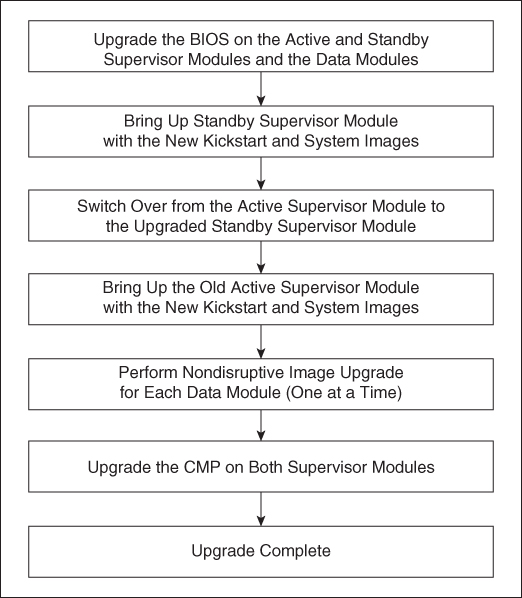
Figure 6-5 ISSU Process
• Nexus 9000 ISSU: The Cisco Nexus 9500 Platform switches are modular switches that are similar to Nexus 7000 switches; they require two supervisors. The minimum configuration required is two system controllers and two fabric modules.
Modular Cisco Nexus 9000 Series switches support parallel upgrades as the default method. The parallel method upgrades the modules in batches instead of one after the other for a faster upgrade. In the upgrade sequence, first the supervisors are upgraded (requires a switchover), then the line cards, fabric modules, system controllers, and the Fabric Extender (FEX). After switchover is performed in a parallel upgrade, the secondary supervisor takes over, and the installer determines the current line cards and fabric modules. It then divides the components into buckets. It places the first half of the line cards in the first bucket, the first half of the fabric modules in the second bucket, the second half of line cards in the third bucket, the second half of the fabric modules in the fourth bucket, the first system controller in the fifth bucket, and the second system controller in the sixth bucket (see Figure 6-6). Each bucket is upgraded successfully before the upgrade process starts for the next bucket. The console shows which modules are assigned to which bucket and status of the upgrade. You have the option to choose a serial upgrade using the CLI.
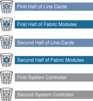
Figure 6-6 Nexus 9500 Parallel Upgrade Process
Cisco Nexus 9300 Series Switches are standalone switches with single supervisors. The ISSU on the Cisco Nexus 9300 and 3100 Series switches causes the supervisor CPU to reset and load the new software version. The control plane is inactive during this time, but the data plane keeps forwarding packets leading to an upgrade with no service disruption. After the CPU loads the updated version of NX-OS, the system restores the control plane to a previous known configuration and runtime state and gets in-sync with the data plane, thereby completing the ISSU process. Because the data plane keeps forwarding packets while the control plane is upgraded, any servers connected to the Cisco Nexus 9300 and 3100 Series switch access layer should see no traffic disruption.
When an upgrade is performed, the control plane is reset. This reset causes spanning tree to time out to its neighboring devices, which results in a spanning tree topology change. In addition, if the switch undergoing the ISSU is the spanning tree root, it might not be able to send bridge protocol data units (BPDUs) during the ISSU process. If there are downstream switches connected to devices undergoing the ISSU, as a best practice, you should use a vPC design for the ISSU. The vPC offers the advantage of running even if the two vPC peer devices operate with different NX-OS releases. During the transition phase, the vPC continues to work even if the peer devices use different NX-OS code. A configuration lock during the ISSU prevents synchronous upgrades on both vPC peer devices simultaneously (configuration is automatically locked on the other vPC peer device when the ISSU is initiated). This feature enables support for a nondisruptive upgrade for the vPC domain.
When the spanning tree primary switch undergoes the ISSU, it notifies the spanning tree secondary switch so that it can tune its spanning tree timers. If the switches are spanning tree root switches, the peer switch should be enabled. The peer switch allows both devices to share a common bridge ID when sending BPDUs. Because the peer switch is enabled, the spanning tree secondary switch continues to send BDPUs to its connected devices to avoid a spanning tree topology change while the spanning tree primary switch undergoes the ISSU.
Nexus Disruptive and Nondisruptive Upgrade/Downgrade Procedure
The following steps show the upgrade/downgrade preparation process:
Step 1. Log in to the device using a console port connection.
Step 2. Download the required kickstart and system software files from Cisco.com to a server.
Step 3. Ensure that the required space is available for the image file(s) to be copied. For a dual supervisor device, verify the standby supervisorcas well.
switch# dir bootflash:
49152    Dec 10 14:43:39 2015 lost+found/
80850712 Dec 10 15:57:44 2015 n9000-dk9.7.0.3.I1.1.bin
...

Usage for bootflash://sup-local
 4825743360 bytes used
16312102912 bytes free
21137846272 bytes total


For Standby Sup (Dual Sup device)

switch# dir bootflash://sup-standby/
49152    Dec 10 14:43:39 2015 lost+found/
80850712 Dec 10 15:57:44 2015 n9000-dk9.7.0.3.I1.1.bin
...

Usage for bootflash://sup-standby
 4825743360 bytes used
16312102912 bytes free
21137846272 bytes total
Note
Cisco recommends that you have the kickstart and system image files for at least one previous release of the Cisco NX-OS software on the device to use if the new image files do not load successfully.
Step 4. If you need more space on the active supervisor module, delete unnecessary files to make space available.
switch# delete bootflash:n9000-dk9.7.0.3.I1.1.bin
For dual supervisor, delete the image from standby supervisor as well.
switch# delete bootflash://sup-standby/n9000-dk9.7.0.3.I1.1.bin
Step 5. Copy the NX-OS kickstart and system images to the active supervisor module bootflash using a transfer protocol. You can use ftp:, tftp:, scp:, or sftp:. The examples in this procedure use scp:.
switch# copy scp://[email protected]//download/nxos.7.0.3.I2.1.bin bootflash:nxos.7.0.3.I2.1.bin
Step 6. Verify the SHA256 checksum for the file to verify the operating system integrity and ensure that the downloaded image is safe to install and use.
switch# show file bootflash://sup-1/nxos.7.0.3.I2.1.bin sha256sum
5214d563b7985ddad67d52658af573d6c64e5a9792b35c458f5296f954bc53be
Step 7. Read the release notes for the related image file.
The following steps show how to use upgrade/downgrade pre-checks:
Step 1. Enter the show incompatibility command to verify that the target image is feature-wise compatible with the current image.
switch# show incompatibility-all nxos bootflash:n9000-dk9.7.0.3.I1.1.bin
Checking incompatible configuration(s)
No incompatible configurations
Step 2. Enter the show install all impact command to identify the impact. This will show if you can upgrade using ISSU or it will be disruptive.
switch# show install all impact nxos bootflash:n9000-dk9.7.0.3.I1.1.bin
Installer will perform compatibility check first. Please wait.
uri is: /n9000-dk9.7.0.3.I1.1.bin
Installer is forced disruptive

Verifying image bootflash:/n9000-dk9.7.0.3.I1.1.bin for boot variable “nxos”.
[####################] 100% -- SUCCESS

Verifying image type.
[####################] 100% -- SUCCESS

Preparing “lcn9k” version info using image bootflash:/n9000-dk9.7.0.3.I1.1.bin.
[####################] 100% -- SUCCESS

Preparing “bios” version info using image bootflash:/n9000-dk9.7.0.3.I1.1.bin.
[####################] 100% -- SUCCESS

Preparing “lcn9k” version info using image bootflash:/n9000-dk9.7.0.3.I1.1.bin.
[####################] 100% -- SUCCESS

Preparing “lcn9k” version info using image bootflash:/n9000-dk9.7.0.3.I1.1.bin.
[####################] 100% -- SUCCESS

Preparing “lcn9k” version info using image bootflash:/n9000-dk9.7.0.3.I1.1.bin.
[####################] 100% -- SUCCESS

Preparing “lcn9k” version info using image bootflash:/n9000-dk9.7.0.3.I1.1.bin.
[####################] 100% -- SUCCESS

Preparing “lcn9k” version info using image bootflash:/n9000-dk9.7.0.3.I1.1.bin.
[####################] 100% -- SUCCESS

Preparing “nxos” version info using image bootflash:/n9000-dk9.7.0.3.I1.1.bin.
[####################] 100% -- SUCCESS

Preparing “lcn9k” version info using image bootflash:/n9000-dk9.7.0.3.I1.1.bin.
[####################] 100% -- SUCCESS

Preparing “lcn9k” version info using image bootflash:/n9000-dk9.7.0.3.I1.1.bin.
[####################] 100% -- SUCCESS

Performing module support checks.
[####################] 100% -- SUCCESS

Notifying services about system upgrade.
[####################] 100% -- SUCCESS
Compatibility check is done:
Module  bootable     Impact           Install-type  Reason
------  --------    --------------   ------------  ------
1        yes        disruptive       reset           Reset due to
                                                     single supervisor
21       yes        disruptive       reset           Reset due to
                                                     single supervisor
22       yes        disruptive       reset           Reset due to
                                                     single supervisor
 23       yes        disruptive       reset           Reset due to
                                                     single supervisor
 24       yes        disruptive       reset           Reset due to
                                                     single supervisor
 25       yes        disruptive       reset           Reset due to
                                                     single supervisor
 26       yes        disruptive       reset           Reset due to
                                                     single supervisor
 27       yes        disruptive       reset           Reset due to
                                                     single supervisor
29        yes        disruptive       reset           Reset due to
                                                     single supervisor
30        yes        disruptive       reset           Reset due to
                                                     single supervisor

Images will be upgraded according to following table:
Module  Image  Running-Version(pri:alt)   New-Version  Upg-Required
------  ------  ------------------------- ------------ -----------
 1      lcn9k   7.0(3)I2(1)               7.0(3)I1(1)   yes
 1      bios    v01.42(00       v01.42(00:v01.42(00     no
 21     lcn9k   7.0(3)I2(1)               7.0(3)I1(1)   yes
 21     bios    v01.42(00       v01.42(00:v01.42(00     no
 22     lcn9k   7.0(3)I2(1)               7.0(3)I1(1)   yes
 22     bios    v01.42(00       v01.42(00:v01.42(00     no
 23     lcn9k   7.0(3)I2(1)               7.0(3)I1(1)   yes
 23     bios    v01.42(00       v01.42(00:v01.42(00     no
 24     lcn9k   7.0(3)I2(1)               7.0(3)I1(1)   yes
 24     bios    v01.42(00       v01.42(00:v01.42(00     no
 25     lcn9k   7.0(3)I2(1)               7.0(3)I1(1)   yes
 25     bios    v01.42(00       v01.42(00:v01.42(00     no
 26     nxos    7.0(3)I2(1)         7.0(3)I1(1)          no
 26     bios    v01.42(00       v01.42(00:v01.42(00     no
 27     nxos    7.0(3)I2(1)        7.0(3)I1(1)           no
 27     bios    v01.42(00       v01.42(00:v01.42(00     no
 29     lcn9k   7.0(3)I2(1)        7.0(3)I1(1)          yes
 29     bios    v01.42(00       v01.42(00:v01.42(00     no
 30     lcn9k   7.0(3)I2(1)         7.0(3)I1(1)         yes
 30     bios    v01.42(00       v01.42(00:v01.42(00     no
After pre-check, you can start the software upgrade/downgrade process. The following steps show the upgrade/downgrade process:
Step 1. Enter the install all command to update to the latest Cisco NX-OS software.
switch# install all nxos bootflash:n9000-dk9.7.0.3.I1.1.bin
Step 2. Peruse the installer impact analysis and accept to proceed.
After the upgrade/downgrade is complete, you can follow these steps to verify the upgrade/downgrade status and software version.
Step 1. Enter the show install all status command to verify the status of the installation.
switch# show install all status
Step 2. Log in and verify that the device is running the required software version.
switch# show version
Nexus Configuration Management
Configuration Management (CM) enables you to control and track changes that are made to a device configuration. CM uses a change management feature to back up device configurations and also to set up a rollback checkpoint that helps clear all configuration changes.
![]()
NX-OS Configuration Save and Backup
The Cisco NX-OS software has two types of configuration files: running configuration and startup configuration. The device uses the startup configuration (startup-config) during device startup to configure the software features. The running configuration (running-config) contains the current changes that you make to the startup configuration file. The two configuration files can be different. You might want to change the device configuration for a short time period rather than permanently. In this case, you would change the running configuration by using commands in global configuration mode but not save the changes to the startup configuration.
Configuration files contain the Cisco NX-OS software commands used to configure the features on a Cisco Nexus device. Commands are parsed (translated and executed) by the Cisco NX-OS software when the system is booted (from the startup-config file) or when you enter commands at the CLI in a configuration mode.
To change the startup configuration file, you need to save the running-configuration file to the startup configuration using the following command:
copy running-config startup-config
The NX-OS copy command also can be used to back up the running configuration to the remote server using tftp: or ftp: or scp: or sftp: protocols:
copy running-config scheme://server/[url /]filename
You can configure Cisco NX-OS by using a file saved on the remote server. The command is similar, except that the source is the remote file and the destination is the running configuration:
copy scheme://server/[url /]filename running-config
Many automation tools provide config archive and config change tracking. Cisco Prime is one Cisco tool that offers regular configuration archives.
Nexus Config Rollback and Checkpoint
The NX-OS rollback feature enables you to take a snapshot, or user checkpoint, of Cisco NX-OS configuration and then reapply that configuration to the device at any point without having to reload the device. A rollback allows any authorized user to apply this checkpoint configuration without requiring expert knowledge of the features configured in the checkpoint.
Cisco NX-OS automatically creates system checkpoints. You can use either a user or system checkpoint to perform a rollback. You can create a checkpoint copy of the current running configuration at any time by using this command:
checkpoint {[ cp-name ] [ description descr ] | file filename }
Cisco NX-OS saves this checkpoint as an ASCII file that you can use to roll back the running configuration to the checkpoint configuration at a future time. You can create multiple checkpoints to save different versions of your running configuration.
To roll back the running configuration, you use the following command:
rollback running-config { checkpoint cp-name | file cp-file } [ atomic | best-effort | stop-at-first-failure ]
The rollback trigger types are
• atomic: Implements a rollback only if no errors occur.
• best-effort: Implements a rollback and skips any errors.
• stop-at-first-failure: Implements a rollback that stops if an error occurs.
The default rollback type is atomic.
When you are ready to roll back to a checkpoint configuration, you can view the changes that will be applied to the current running configuration before committing to the rollback operation using show diff rollback-patch.
show diff rollback-patch { checkpoint src-cp-name | running-config | startup-config | file source-file } { checkpoint dest-cp-name | running-config | startup-config | file dest-file }
If an error occurs during the rollback operation, you can choose to cancel the operation, or you can ignore the error and proceed with the rollback. If you cancel the operation, Cisco NX-OS provides a list of changes already applied before the error occurred. You need to clean up these changes manually.
To create a checkpoint named chk, you can verify the difference and rollback by skipping any errors:
Step 1. Create a checkpoint named chk with the description first check point.
switch# checkpoint chk description first check point
Step 2. Verify that the checkpoint was created.
switch# show checkpoint chk
-----------------------------------------------------------------------
Name: chk
!Command: Checkpoint cmd vdc 1
!Time: Sun Sep 8 11:51:50 2019
version 7.3(0)D1(1)
power redundancy-mode redundant
vdc switch id 1
limit-resource module-type m1 m1xl m2xl f2e
allocate interface Ethernet2/1-48
allocate interface Ethernet3/1-48
allocate interface Ethernet4/1-48
Step 3. Apply any new configurations.
Step 4. Verify the difference between the checkpoint and current running configuration.
switch# show diff rollback-patch checkpoint chk running-config

Collecting Running-Config
#Generating Rollback Patch
!!
interface Ethernet2/2
no shutdown
exit
!
interface Ethernet2/2
ip address 10.10.20.1/24
no shutdown
Step 5: Roll back from chk, skipping any errors.
switch# rollback running-config checkpoint  chk
Note: Applying config parallelly may fail Rollback verification
Collecting Running-Config
#Generating Rollback Patch
Executing Rollback Patch
Generating Running-config for verification
Generating Patch for verification
Verification is Successful.
Rollback completed successfully.
Cisco NX-OS can automatically generate system checkpoints to help you avoid a loss of configuration information. System checkpoints are generated by the following events:
• When an enabled feature is disabled with the no feature command
• When an instance of a Layer 3 protocol is removed, such as with the no router bgp command or the no ip pim sparse-mode command
• When a feature’s license expires
If one of these events causes system configuration changes, the feature software creates a system checkpoint that you can use to roll back to the previous system configuration.
The system-generated checkpoint filenames begin with “system-” and include the feature name. For example, the first time that you disable the BGP feature, the system creates the checkpoint named system-fm-__inst_1__bgp.
Network Infrastructure Monitoring
Network monitoring is important for data center visibility and management. Today’s resource-intensive applications are causing network traffic to grow exponentially, putting high demands on the existing data center infrastructure. Companies are finding it challenging to differentiate critical applications from noncritical ones and to dynamically allocate network resources to higher-priority applications. To better manage network resources and be proactive, network administrators need visibility into the network traffic. Network monitoring will improve operational efficiency. The system management features of the Cisco Nexus switch allow you to monitor and manage your network for efficient device use, diagnostics, troubleshooting, and logging.
Cisco Nexus supports the following network monitoring tools:
• Notifications about network activity using system message logging
• Notifications about device status using logging or SNMP traps
• Cisco Call Home
• Export of network traffic flows using NetFlow
• Network traffic mirroring (SPAN)
![]()
NX-OS System Message Logging
Logging can be used for fault notification, network forensics, and security auditing. Cisco Nexus log messages can be handled in five different ways:
• Console logging: By default, Cisco Nexus sends all log messages to its console port. Hence, only the users who are physically connected to the router console port can view these messages.
• Terminal logging: It is similar to console logging, but it displays log messages to Cisco Nexus a Telnet or SSH session instead. This is not enabled by default; Cisco recommends that you enable it on a second monitoring session.
• Buffered logging: This type of logging uses Cisco Nexus RAM for storing log messages. The buffer has a fixed size to ensure that the log will not deplete valuable system memory. The Cisco Nexus switch accomplishes this by deleting old messages from the buffer as new messages are added.
• Syslog server logging: Cisco Nexus can use syslog to forward log messages to external syslog servers for storage. This type of logging is not enabled by default.
• SNMP trap logging: The router is able to use SNMP traps to send log messages to an external SNMP server.
You can use system message logging to control the destination and to filter the severity level of messages that system processes generate. You can configure logging to terminal sessions, a log file, and syslog servers on remote systems.
Logging messages are categorized as having a severity level of 7. When you configure the severity level, the system outputs messages at that level and all lower levels. For example, if you configure the system to log severity level 4, the system will log severity levels 4, 3, 2, 1, and 0. Table 6-2 lists all the different severity levels.
Table 6-2 System Message Severity Levels

The device logs the most recent 100 messages of severity level 0, 1, or 2 to the NVRAM log. You cannot configure logging to the NVRAM.
You can configure which system messages should be logged based on the facility that generated the message and its severity level.
Cisco Nexus can send logs to any syslog server. Syslog servers run on remote systems that log system messages based on the syslog protocol. NX-OS supports up to eight IPv4 or IPv6 syslog servers per device.
Network Time Management
Time management or time synchronization is a critical component of any network. Every aspect of managing, securing, and debugging a network requires an accurate event time. Accurate timestamping is key to determine when a configuration changed or problems occurred and to find time correlations.
Cisco Nexus has an internal clock, and that clock needs to be configured to reflect the correct time. It is recommended that you sync the time with an accurate time source. If the time is set manually on all devices in a data center, these times will be ahead or behind a few seconds, or they will drift randomly, and after some time, all devices will be out of sync. If network devices are out of sync by a few milliseconds or, in extreme cases a few seconds, it can be very difficult for you to determine the sequence of events if a problem should occur.
Cisco NX-OS supports the Network Time Protocol (NTP) to synchronize time. NTP uses the User Datagram Protocol (UDP) as its transport protocol. All NTP communications use Coordinated Universal Time (UTC). Cisco NX-OS also supports Precision Time Protocol (PTP); its hardware timestamp feature provides greater accuracy than NTP.
![]()
Network Time Protocol
The Network Time Protocol (NTP) synchronizes the time among a set of distributed time servers and clients so that you can correlate events when you receive system logs and other time-specific events from multiple network devices.
An NTP server usually receives its time from a source such as a radio clock or an atomic clock attached to a time server and then distributes this time across the network. NTP is extremely efficient; no more than one packet per minute is necessary to synchronize two machines to within a millisecond of each other.
NTP uses a stratum to describe the distance between a network device and an authoritative time source, as shown in Figure 6-7:
• A stratum 1 time server is directly attached to an authoritative time source (such as an atomic clock).
• A stratum 2 NTP server receives its time through NTP from a stratum 1 NTP server.
![]()

Figure 6-7 NTP Stratum
Before synchronizing, NTP compares the time reported by several network devices and does not synchronize with one that is significantly different, even if it is a stratum 1.
Because Cisco NX-OS cannot connect to a radio or atomic clock and act as a stratum 1 server, Cisco recommends that you use the public NTP servers available on the Internet.
If the network is isolated from the Internet, Cisco NX-OS allows you to configure the time as though it were synchronized through NTP, even though it was not.
The time kept on a device is a critical resource; it is strongly recommended that you use NTP security features to avoid any accidental or malicious setting of incorrect time. Two mechanisms are available: an access list-based restriction scheme and an encrypted authentication mechanism.
Table 6-3 lists the NTP default parameters. You can alter NTP parameters as necessary.
Table 6-3 NTP Default Settings

Tables 6-4 through 6-5 describe the most-used NTP configuration commands. For a full list of the commands, refer to the Nexus System Management Configuration Guide links shown in the reference list at the end of this chapter.
Table 6-4 NTP Global Commands


Table 6-5 NTP Verification Commands

Example 6-9 shows the NTP configuration to sync with Internet NTP servers, sourcing NTP traffic from VLAN 10.
Example 6-9 NX-OS NTP Configuration Example
Nexus# configure terminal


!--- Form an association with a server. Use the prefer keyword to make this
!--- server as preferred NTP server.

Nexus(config)# ntp server 129.6.15.28 prefer
Nexus(config)# ntp server 129.6.15.29

!--- Configure the source interface for all NTP packets.

Nexus(config)# ntp source-interface vlan10

!--- Configure the device as an authoritative NTP server.

Nexus(config)# ntp master 1

Nexus(config)# interface vlan10
Nexus(config-if)# no shutdown
Nexu(config-if)# no ip redirects
Nexus(config-if)# ip address 172.20.100.34/24
Example 6-10 shows the NTP sync process. The NTP server is configured (including the local device) and the NTP is synced with preferred server 129.6.15.28.
Example 6-10 NX-OS NTP Status
Nexus# show ntp peers
--------------------------------------------------
  Peer IP Address               Serv/Peer
--------------------------------------------------
  127.127.1.0                   Server (configured)
  129.6.15.28                   Server (configured)
  129.6.15.29                   Server (configured)


Use the show ntp peer-status command in order to display the status for all NTP servers and peers.
For example:

Nexus# show ntp peer-status
Total peers : 3
* - selected for sync, + -  peer mode(active),
- - peer mode(passive), = - polled in client mode
    remote               local                 st   poll   reach delay   vrf
-------------------------------------------------------------------------------
=127.127.1.0            172.20.100.34           1   64       0   0.00000
*129.6.15.28            172.20.100.34           1   64     377   0.03938 default
=129.6.15.29            172.20.100.34           1   64     377   0.01804 default
Precision Time Protocol
The Precision Time Protocol (PTP) is a time synchronization protocol for nodes distributed across a network. Its hardware timestamp feature provides greater accuracy than other time synchronization protocols compared to the Network Time Protocol (NTP).
A PTP system can consist of a combination of PTP and non-PTP devices. These PTP devices include ordinary clocks, boundary clocks, and transparent clocks. Non-PTP devices include ordinary network switches, routers, and other infrastructure devices.
PTP is a distributed protocol that specifies how real-time PTP clocks in the system synchronize with each other. These clocks are organized into a master-member synchronization hierarchy with the grandmaster clock, the clock at the top of the hierarchy, determining the reference time for the entire system. Synchronization is achieved by exchanging PTP timing messages, with the members using the timing information to adjust their clocks to the time of their master in the hierarchy. PTP operates within a logical scope called a PTP domain. Figure 6-8 shows an example of a PTP domain.
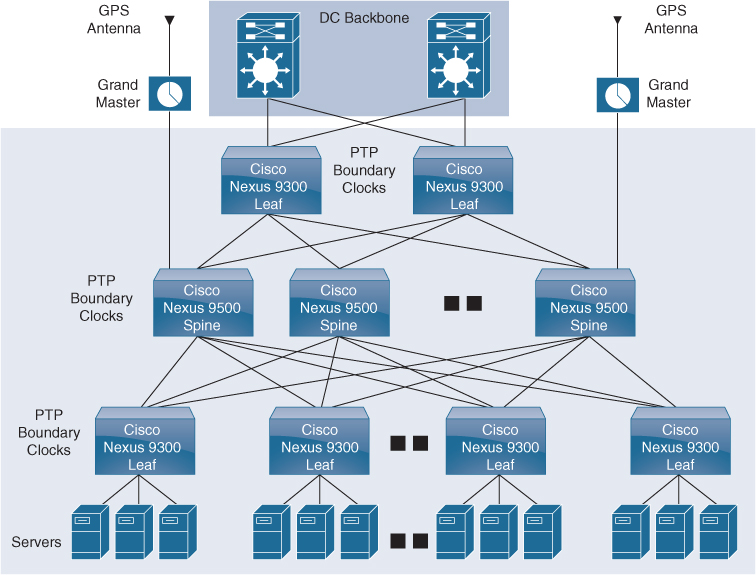
Figure 6-8 PTP Domain
The following clocks are common PTP devices:
• Ordinary clock: Communicates with the network based on a single physical port, similar to an end host. An ordinary clock can function as a grandmaster clock.
• Boundary clock: Typically has several physical ports, with each port behaving like a port of an ordinary clock. However, each port shares the local clock, and the clock data sets are common to all ports. Each port decides its individual state, either master (synchronizing other ports connected to it) or member (synchronizing to a downstream port), based on the best clock available to it through all of the other ports on the boundary clock. Messages related to synchronization and establishing the master-member hierarchy terminate in the protocol engine of a boundary clock and are not forwarded.
• Transparent clock: Forwards all PTP messages like an ordinary switch or router but measures the residence time of a packet in the switch (the time that the packet takes to traverse the transparent clock) and in some cases the link delay of the ingress port for the packet. The ports have no state because the transparent clock does not need to synchronize to the grandmaster clock.
• End-to-end transparent clock: Measures the residence time of a PTP message and accumulates the times in the correction field of the PTP message or an associated follow-up message.
• Peer-to-peer transparent clock: Measures the residence time of a PTP message and computes the link delay between each port and a similarly equipped port on another node that shares the link. For a packet, this incoming link delay is added to the residence time in the correction field of the PTP message or an associated follow-up message.
The PTP process consists of two phases: establishing the master-member hierarchy and synchronizing the clocks.
Within a PTP domain, each port of an ordinary or boundary clock follows this process to determine its state:
• Examines the contents of all received announce messages (issued by ports in the master state).
• Compares the data sets of the foreign master (in the announce message) and the local clock for priority, clock class, accuracy, and so on.
• Based on this comparison, determines its own state as either master or member.
After the master-member hierarchy has been established, the clocks are synchronized as follows:
• The master sends a synchronization message to the member and notes the time it was sent.
• The member receives the synchronization message and notes the time it was received.
• The member sends a delay-request message to the master and notes the time it was sent.
• The master receives the delay-request message and notes the time it was received.
• The master sends a delay-response message to the member.
• The member uses these timestamps to adjust its clock to the time of its master.
Table 6-6 lists the PTP default parameters. You can alter PTP parameters as necessary.
Table 6-6 PTP Default Settings

Tables 6-7 through 6-9 describe the most-used PTP configuration commands. For a full list of the commands, refer to the Nexus System Management Configuration Guide links shown in the reference list at the end of this chapter.
Table 6-7 PTP Global Commands

Table 6-8 PTP Interface-Level Commands

Table 6-9 PTP Verification Commands

Example 6-11 shows how to configure PTP globally on the device, specify the source IP address for PTP communications, and configure a preference level for the clock:
Example 6-11 NX-OS PTP Configuration Example
switch# configure terminal
switch(config)# feature ptp
switch(config)# ptp source10.10.10.1
switch(config)# ptp priority11
switch(config)# ptp priority21
Example 6-12 shows the PTP device boundary type. There is no port configured as a PTP port; all other parameters have default values.
Example 6-12 NX-OS PTP Clock Status
switch(config)# show ptp clock
PTP Device Type: Boundary clock
Clock Identity: 0:22:55:ff:ff:79:a4:c1
Clock Domain:0
Number of PTP ports: 0
Priority1: 1
Priority2: 1
ClockQuality:
Class: 248
Accuracy: 254
Offset(log variance): 65535
Offset From Master: 0
Mean Path Delay: 0
Steps removed: 0
Local clock time: Sun Jul 7 14:13:24 2019
![]()
NX-OS Simple Network Management Protocol
The Simple Network Management Protocol (SNMP) is an application layer protocol that provides a message format for communication between SNMP managers and agents. SNMP provides a standardized framework and a common language used for the monitoring and management of devices in a network.
The SNMP framework consists of three parts:
• SNMP manager: The system used to control and monitor the activities of network devices using SNMP.
• SNMP agent: The software component within the managed device that maintains the data for the device and reports this data, as needed, to manage systems. The Cisco Nexus device supports the agent and MIB. To enable the SNMP agent, you must define the relationship between the manager and the agent.
• Management information base (MIB): The collection of managed objects on the SNMP agent.
SNMP is defined in RFCs 3411 to 3418. Cisco Nexus supports SNMPv1, SNMPv2c, and SNMPv3. Both SNMPv1 and SNMPv2c use a community-based form of security. Cisco NX-OS supports SNMP over IPv6.
A key feature of SNMP is the ability to generate notifications from an SNMP agent. These notifications do not require that requests be sent from the SNMP manager. Notifications can indicate improper user authentication, restarts, the closing of a connection, the loss of connection to a neighbor router, or other significant events.
Cisco NX-OS generates SNMP notifications as either traps or informs. A trap is an asynchronous, unacknowledged message sent from the agent to the SNMP managers listed in the host receiver table. Informs are asynchronous messages sent from the SNMP agent to the SNMP manager that the manager must acknowledge receipt of.
Traps are less reliable than informs because the SNMP manager does not send any acknowledgment when it receives a trap. The device cannot determine if the trap was received. An SNMP manager that receives an inform request acknowledges the message with an SNMP response protocol data unit (PDU). If the device never receives a response, it can send the inform request again.
You can configure Cisco NX-OS to send notifications to multiple host receivers.
Table 6-10 lists the SNMP traps that are enabled by default.
Table 6-10 SNMP Traps

SNMPv3 provides secure access to devices through a combination of authenticating and encrypting frames over the network. The security features provided in SNMPv3 are the following:
• Message integrity: Ensures that a packet has not been tampered with in-transit.
• Authentication: Determines the message is from a valid source.
• Encryption: Scrambles the packet contents to prevent it from being seen by unauthorized sources.
SNMPv3 provides for both security models and security levels. A security model is an authentication strategy that is set up for a user and the role in which the user resides. A security level is the permitted level of security within a security model. A combination of a security model and a security level determines which security mechanism is employed when handling an SNMP packet.
The security level determines if an SNMP message needs to be protected from disclosure and if the message needs to be authenticated. The various security levels that exist within a security model are as follows:
• noAuthNoPriv: Security level that does not provide authentication or encryption. This level is not supported for SNMPv3.
• authNoPriv: Security level that provides authentication but does not provide encryption.
• authPriv: Security level that provides both authentication and encryption.
Three security models are available: SNMPv1, SNMPv2c, and SNMPv3. The security model combined with the security level determines the security mechanism applied when the SNMP message is processed. Table 6-11 identifies what the combinations of security models and levels mean.
![]()
Table 6-11 SNMP Security Models and Levels

Tables 6-12 through 6-15 describe the most-used SNMPconfiguration commands. For a full list of the commands, refer to the Nexus System Management Configuration Guide links shown in the reference list at the end of this chapter.
Table 6-12 SNMP Global Commands

Table 6-13 SNMP MIBs


Table 6-14 SNMP Specific Notification Commands

Table 6-15 SNMP Verification Commands

Example 6-13 shows how to configure Cisco NX-OS to send the Cisco link Up or Down notifications to a notification host receiver using the Blue VRF and defines two SNMP users—Admin and NMS.
Example 6-13 NX-OS SNMP Configuration Example
switch# config t
switch(config)# snmp-server contact [email protected]
switch(config)# snmp-server user Admin auth sha abcd1234 priv abcdefgh
switch(config)# snmp-server user NMS auth sha abcd1234 priv abcdefgh engineID 00:00:00:63:00:01:00:22:32:15:10:03
switch(config)# snmp-server host 192.0.2.1 informs version 3 auth NMS
switch(config)# snmp-server host 192.0.2.1 use-vrf Blue
switch(config)# snmp-server enable traps link cisco
Example 6-14 shows how to configure SNMP to send traps using an in-band port configured at the host level.
Example 6-14 NX-OS SNMP Destination Trap Server and Source Interface Configuration
switch(config)# snmp-server host 171.71.48.164 version 2c public
switch(config)# snmp-server host 171.71.48.164 source-interface ethernet 1/2
Example 6-15 shows SNMP verification that shows the destination host with the SNMP version.
Example 6-15 NX-OS SNMP Status
switch(config)# show snmp host
-------------------------------------------------------------------
Host Port Version Level Type SecName
-------------------------------------------------------------------
171.71.48.164 162 v2c noauth trap public
 Source interface: Ethernet 1/2
-------------------------------------------------------------------
Nexus Smart Call Home
Smart Call Home provides an email-based notification for critical system policies. A range of message formats is available for compatibility with pager services, standard email, or XML-based automated parsing applications. You can use this feature to page a network support engineer, email a network operations center, or use Cisco Smart Call Home services to automatically generate a case with the Cisco Technical Assistance Center.
Smart Call Home offers the following features:
• Automatic execution and attachment of relevant CLI command output.
• Multiple message format options such as the following:
• Short Text: Suitable for pagers or printed reports.
• Full Text: Fully formatted message information suitable for human reading.
• XML: Machine-readable format that uses Extensible Markup Language (XML) and Adaptive Messaging Language (AML) XML schema definition (XSD). The AML XSD is published on the Cisco.com website. The XML format enables communication with the Cisco Technical Assistance Center.
• Multiple concurrent message destinations. You can configure up to 50 email destination addresses for each destination profile.
Example 6-16 shows how to configure Smart Call Home to send alerts via email when users configure a new routing protocol using the show ip routing command.
Example 6-16 NX-OS CallHome Configuration Example
switch(config)# snmp-server contact [email protected]
switch(config)# callhome
switch(config-callhome)# email-contact [email protected]
switch(config-callhome)# phone-contact +1-800-123-4567
switch(config-callhome)# street-address 123 Anystreet st. Anytown,AnyWhere
switch(config-callhome)# destination-profile Noc101 full-text
switch(config-callhome)# destination-profile full-text-destination email-addr [email protected]
switch(config-callhome)# destination-profile full-text-destination message-level 5
switch(config-callhome)# destination-profile Noc101 alert-group Configuration
switch(config-callhome)# alert-group Configuration user-def-cmd “show ip routing”
switch(config-callhome)# transport email smtp-server 192.0.2.10 use-vrf Red
switch(config-callhome)# enable
switch(config-callhome)# commit
![]()
Nexus NetFlow
Today data center administrators need detailed profiles of applications that traverse their networks. To efficiently operate, scale, and consolidate their networks, administrators need to know what applications are consuming bandwidth, who is using them, when they are being used, and what activities are prevalent in the data center. With this information, data center administrators have visibility into their networks, which is crucial in exerting control over the network, finding the precise reasons for performance problems and possible security concerns, and managing the overall end-user experience.
The capability to characterize IP traffic and understand who sent it, the traffic destination, the time of day, and the application information is critical for data center operations. It helps data center managers determine how to optimize resource utilization, plan network capacity, build traffic pattern models for consolidation, and determine where to apply quality of service (QoS), and it plays a vital role in network security for detection of DoS attacks and network-propagated worms (see Figure 6-9).

Figure 6-9 NetFlow Traffic Export
NetFlow identifies packet flows for ingress IP packets and provides statistics based on these packet flows. NetFlow does not require any change to either the packets themselves or any networking device.
NetFlow uses flows to provide statistics for accounting, network monitoring, and network planning. A flow is a unidirectional stream of packets that arrives on a source interface (or VLAN) and has the same values for the keys. A key is an identified value for a field within the packet. You create a flow using a flow record to define the unique keys for your flow.
Cisco NX-OS supports the flexible NetFlow feature that enables enhanced network anomalies and security detection. Flexible NetFlow allows you to define an optimal flow record for a particular application by selecting the keys from a large collection of predefined fields.
All key values must match for the packet to count in a given flow. A flow might gather other fields of interest, depending on the export record version that you configure. Flows are stored in the NetFlow cache.
You can export the data that NetFlow gathers for your flow by using a flow exporter and export this data to remote NetFlow analytic tools, such as the Cisco Prime Network Analysis Module (NAM) or Cisco Stealthwatch.
Cisco NX-OS exports a flow as part of a NetFlow export UDP datagram under the following circumstances:
• Flows are exported periodically as per the flow timeout value, which defaults to 10 seconds if not configured.
• You have forced the flow to export.
The flow record determines the size of the data to be collected for a flow. The flow monitor combines the flow record and flow exporter with the NetFlow cache information.
Cisco NX-OS can gather NetFlow statistics and analyze all packets on the interface or subinterface.
Unlike other Cisco Nexus platforms, Cisco Nexus 9000 Series switches separate NetFlow processing into two layers:
• The first layer supports per-packet visibility for line-rate traffic. Packets do not need to be sampled and statistically analyzed. Instead, the packets can be processed and aggregated at line rate.
• The second layer enables the gathering of flows at scale. It can maintain hundreds of thousands of flows without losing any flows and periodically exports them to an external collector.
NetFlow configuration parameters are as follows:
• Flow records: A flow record defines the keys that NetFlow uses to identify packets and other fields of interest that NetFlow gathers for the flow. You can define a flow record with any combination of keys and fields of interest. Cisco NX-OS supports a rich set of keys. A flow record also defines the types of counters gathered per flow. You can configure 32- or 64-bit packet or byte counters.
The key fields are specified with the match keyword. The fields of interest and counters are specified under the collect keyword.
Cisco NX-OS enables the following match fields as the defaults when you create a flow record:
• match interface input
• match flow direction
• Flow exporters: A flow exporter contains network layer and transport layer details for the NetFlow export packet. You can configure the following information in a flow exporter:
• Export destination IP address
• Source interface
• UDP port number (where the NetFlow Collector is listening for NetFlow packets): The default value is 9995.
Note
NetFlow export packets use the IP address that is assigned to the source interface. If the source interface does not have an IP address assigned to it, the flow exporter drops flows that were meant to be exported.
Cisco NX-OS exports data to the NetFlow Collector whenever a timeout occurs. You can configure a flush cache timeout (using the flow timeout command) to flush the cache and force a flow export.
• Export format: Cisco NX-OS supports the Version 9 export format. This format supports a more efficient network utilization than the older Version 5 export format and supports IPv6 and Layer 2 fields. In addition, the Version 9 export format supports the full 32-bit SNMP ifIndex values at the NetFlow Collector.
• Layer 2 NetFlow keys: You can define Layer 2 keys in flexible NetFlow records that you can use to capture flows in Layer 2 interfaces. The Layer 2 keys are as follows:
• Source and destination MAC addresses
• Source VLAN ID
• EtherType from the Ethernet frame
You can apply Layer 2 NetFlow to the following interfaces for the ingress direction:
• Switch ports in access mode
• Switch ports in trunk mode
• Layer 2 port channels
Note
You cannot apply Layer 2 NetFlow to VLANs, egress interfaces, or Layer 3 interfaces such as VLAN interfaces.
Example 6-17 shows how to configure a NetFlow exporter configuration for IPv4.
Example 6-17 NX-OS NetFlow Configuration Example
feature netflow
flow exporter example1
 version 9
flow record record1
 match ipv4 source address
 match ipv4 destination address
 collect counter bytes
 collect counter packets
flow monitor flow1
 record record1
 exporter export1
interface Ethernet2/45
 ip flow monitor flow1 input
 ip address 10.20.1.1/24
 no shutdown
Example 6-18 shows a NetFlow exporter configuration for IPv4 from the Cisco Nexus switch to the NAM.
Example 6-18 NX-OS NetFlow to Cisco NAM Configuration Example
flow exporter exp1
  destination 172.20.101.87 use-vrf management
  transport udp 3000
  source mgmt0
  version 9

flow record exp1
  match ipv4 source address
  match ipv4 destination address
  match ip protocol
  match ip tos
  match transport source-port
  match transport destination-port
  collect counter bytes long
  collect counter packets long
  collect timestamp sys-uptime first
  collect timestamp sys-uptime last
  collect ip version

flow monitor exp1
  record exp1
  exporter exp1

interface Ethernet2/9
  ip flow monitor exp1 input
  ip flow monitor exp1 output
Example 6-19 shows a sample output for the show hardware flow ip command.
Example 6-19 NX-OS NetFlow Hardware Flow Status
switch(config-if)# show hardware flow ip

D - Direction; L4 Info - Protocol:Source Port:Destination Port
IF - Interface: (Eth)ernet, (S)vi, (V)lan, (P)ortchannel, (T)unnel
TCP Flags: Ack, Flush, Push, Reset, Syn, Urgent

D  IF          SrcAddr              DstAddr            L4 Info              PktCnt     TCP Fl
--+----------- +---------------+    ---------------+   ---------------+     ----------+------
CP sup-eth1    010.014.014.002      010.014.014.001    001:00000:00000      0000000021 ......
Example 6-20 shows sample output for the show running-configuration netflow command.
Example 6-20 NX-OS NetFlow Status
switch# show running-configuration netflow

version 7.3(0)D1(1)

feature netflow

flow timeout active 60
flow exporter exp1
  destination 10.76.80.132 use-vrf management
  transport udp 9995
  source mgmt0
  version 9
    template data timeout 5
    option sampler-table timeout 8
sampler s3
  mode 2 out-of 3
flow monitor M2
  record netflow ipv4 original-input
  exporter exp1
control-plane
  ip flow monitor M2 output sampler s3
![]()
Switched Port Analyzer
The Switched Port Analyzer (SPAN) feature, which is sometimes called port mirroring or port monitoring, is a method wherein a device sends a copy of all network packets seen on one port (or an entire VLAN) to another port. This allows the copied network to be analyzed for monitoring, troubleshooting, and other purposes. Figure 6-10 illustrates some of the key terms used in a SPAN implementation.
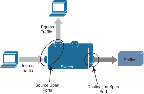
Figure 6-10 SPAN Switch Port
• Ingress traffic: Traffic that enters the switch.
• Egress traffic: Traffic that leaves the switch.
• Source (SPAN) port: A port that is monitored with use of the SPAN feature.
• Source (SPAN) VLAN: A VLAN whose traffic is monitored with use of the SPAN feature.
• Destination (SPAN) port: A port that monitors source ports, usually where a network analyzer is connected.
SPAN ports monitor all traffic for a source port, which sends a copy of the traffic to a destination port. The network analyzer, which is attached with a destination port, analyzes the traffic that passes through the source port.
The source port can be a single port or multiple ports or a VLAN, which is also called a monitored port. You can monitor all the packets for a source port that is received (ingress), transmitted (egress), or bidirectional (both). A replication of the packets is sent to the destination port for analyzation.
For VLAN-based SPAN (VSPAN), all ports in the VLAN are source ports. So, the traffic in the VLAN is monitored. You can apply a VLAN-based filter on the trunk port of the switch to limit the SPAN traffic monitor.
The destination port is one that was connected to a device such as a SwitchProbe device or other Remote Network Monitoring (RMON) probe or security device that can receive and analyze the copied packets from a single or from multiple source ports.
A switch supports multiple SPAN sessions (up to 48 sessions), but only two sessions can be run simultaneously, and others are shut down. A port of the switch is configured as either the source port or the destination port.
Note
SPAN may use the same replication engine as multicast on the module, and there is a physical limit to the amount of replication that each replication engine can do. Nexus 7000 modules have multiple replication engines for each module, and under normal circumstances, multicast is unaffected by a span session. But it is possible to impact multicast replication if you have a large number of high-rate multicast streams inbound to the module, and the port you monitor uses the same replication engine.
Exemple 6-21 shows a SPAN destination port (interface E3/48) configuration.
Example 6-21 NX-OS SPAN Port Configuration
switch-1# configure terminal
switch-1(config)# interface ethernet 3/48

!--- Configures the switchport parameters for a port.

switch-1(config-if)# switchport

!--- Configures the switchport interface as a SPAN destination.

switch-1(config-if)# switchport monitor
switch-1(config-if)# no shut
switch-1(config-if)# exit
Example 6-22 shows a SPAN mirror port (interface E3/11) configuration and sends duplicate traffic to interface E3/48.
Example 6-22 NX-OS SPAN Mirror Port (Source Port) Configuration
switch-1(config)# monitor session 1

!---Configure the source port with traffic direction.

switch(config-monitor)# source interface ethernet 3/11 both

!--- Configure the destination port.

switch7000-1(config-monitor)# destination interface ethernet 3/48

!--- To enable the SPAN session, by default session in shutdown state.

switch7000-1(config-monitor)# no shut
switch7000-1(config-monitor)# exit
Example 6-23 shows active SPAN sessions with the source and destination of a single port/VLAN or group of ports/VLANs.
Example 6-23 NX-OS SPAN Status
The show monitor command gives the status of the SPAN sessions.
switch-1 #show monitor

Session  State        Reason                  Description
-------  -----------  ---------------------- --------------------------------
1        up           The session is up
The show monitor session all command gives a summary of the current SPAN configuration.
switch-1# show monitor session all

  session 1
---------------
type              : local
state             : up
source intf       :
    rx            : Eth3/11
    tx            : Eth3/11
    both          : Eth3/11
source VLANs      :
    rx            :
    tx            :
    both          :
filter VLANs      : filter not specified
destination ports : Eth3/48
Cisco Nexus NX-OS also supports the Encapsulated Remote Switched Port Analyzer (ERSPAN). ERSPAN transports mirrored traffic over an IP network. The traffic is encapsulated at the source router and is transferred across the network. The packet is decapsulated at the destination router and then sent to the destination interface. ERSPAN consists of an ERSPAN source session, routable ERSPAN generic routing encapsulation (GRE)-encapsulated traffic, and an ERSPAN destination session, as shown in Figure 6-11. You separately configure ERSPAN source sessions and destination sessions on different switches.
• ERSPAN enables remote monitoring of multiple switches across your network.
• ERSPAN transports mirrored traffic from source ports of different switches to the destination port, where the network analyzer has connected.
• The traffic is encapsulated at the source switch and is transferred to the destination switch, where the packet is decapsulated and then sent to the destination port.
• ERSPAN consists of an ERSPAN source session, routable ERSPAN generic routing encapsulation (GRE)-encapsulated traffic, and an ERSPAN destination session.
• You can configure ERSPAN source sessions and destination sessions on different switches separately.
• ERSPAN does not monitor any packets that are generated by the supervisor, regardless of their source.
• ERSPAN consists of an ERSPAN source session, routable ERSPAN GRE-encapsulated traffic, and an ERSPAN destination session.
• ERSPAN Source:
• The interfaces from which traffic can be monitored are called ERSPAN sources.
• You can monitor all the packets for the source port that is received (ingress), transmitted (egress), or bidirectional (both).
• ERSPAN sources include source ports, source VLANs, or source VSANs. When a VLAN is specified as an ERSPAN source, all supported interfaces in the VLAN are ERSPAN sources.
• ERSPAN Destination:
• Destination ports receive the copied traffic from ERSPAN sources.
• The destination port is a port that was connected to the device such as a SwitchProbe device or other Remote Monitoring (RMON) probe or security device that can receive and analyze the copied packets from single or multiple source port.
• Destination ports do not participate in any spanning tree instance or any Layer 3 protocols.
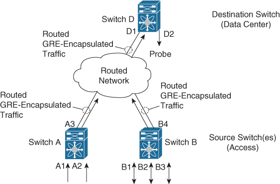
Figure 6-11 ERSPAN Source and Destination Switches
Example 6-24 shows an ERSPAN source switch configuration, SPAN source port (interface E2/10), and destination session (IP address 11.11.11.3/32).
Example 6-24 NX-OS ERSPAN Source Switch Configuration
switch_1# configure terminal

!--- Configures an ERSPAN source session.

switch_1(config)# monitor session 48 type erspan-source

!--- Configure the sources and traffic direction.

switch_1(config-erspan-src)# source interface Ethernet2/10 both

!--- Configure the destination IP address in the ERSPAN session.

switch_1(config-erspan-src)# destination ip 10.11.11.3

!--- Configure the ERSPAN ID.

switch_1(config-erspan-src)# erspan-id 902

!--- Configure the VRF.

switch_1(config-erspan-src)# vrf default

!--- Enable the ERSPAN source session (by default the session is !--- in shutdown state).

switch_1(config-erspan-src)# no shut
switch_1(config-erspan-src)# exit

!--- Configure the ERSPAN global origin IP address.

switch_1(config)# monitor erspan origin ip-address 10.10.10.1 global

!--- Configure the IP address for loopback interface, which is used !--- as source of the ERSPAN traffic.

switch_1(config)# interface loopback1
switch_1(config-if)# ip address 10.10.10.1/32
switch_1(config-if)# exit

switch_1(config)# interface Ethernet1/1
switch_1(config-if)# switchport
switch_1(config-if)# switchport mode trunk
switch_1(config-if)# no shutdown
switch_1(config-if)# exit

switch_1(config)# feature interface-vlan
switch_1(config)# interface Vlan 11
switch_1(config-if)# ip address 10.11.11.2/29
switch_1(config-if)# no ip redirects
switch_1(config-if)# no shutdown
switch_1(config-if)# exit
Example 6-25 shows an ERSPAN destination switch configuration, SPAN destination port (interface E2/34), and source session (address 11.11.11.3/32).
Example 6-25 NX-OS ERSPAN Destination Switch Configuration
switch_2# configure terminal

!--- Configures an ERSPAN destination session.

switch_2(config)# monitor session 47 type erspan-destination

!--- Configures the source IP address.

switch_2(config-erspan-src)# source ip 10.11.11.3

!--- Configures a destination for copied source packets.

switch_2(config-erspan-src)# destination interface Ethernet2/34

!--- Configure the ERSPAN ID.

switch_2(config-erspan-src)# erspan-id 902

!--- Configure the VRF.

switch_2(config-erspan-src)# vrf default

!--- Enable the ERSPAN destination session (by default the session is !--- in shutdown state).

switch_2(config-erspan-src)# no shut
switch_2(config-erspan-src)# exit

switch_2(config)# interface Ethernet2/34
switch_2(config-if)# switchport monitor
switch_2(config-if)# exit

switch_2(config)# feature interface-vlan
switch_2(config)# interface Vlan 11
switch_2(config-if)# ip address 10.11.11.3/29
switch_2(config-if)# no ip redirects
switch_2(config-if)# no shutdown
switch_2(config-if)# exit

switch_2(config)# interface Ethernet1/2
switch_2(config-if)# switchport
switch_2(config-if)# switchport mode trunk
switch_2(config-if)# no shutdown
switch_2(config-if)# exit
Example 6-26 shows the ERSPAN source switch session status.
Example 6-26 NXOS ERSPAN Status
Use the show monitor command in order to display the status of the ERSPAN sessions:
switch_1# show monitor
Session  State        Reason                  Description
-------  -----------  ----------------------  --------------------------------
     4       up        The session is up
Use the show monitor session [session session_number] command in order to display the ERSPAN session configuration:
switch_1# show monitor session 48
   session 48
---------------
type              : erspan-source
state             : up
erspan-id         : 902
vrf-name          : default
acl-name          : acl-name not specified
ip-ttl            : 255
ip-dscp           : 0
destination-ip    : 10.11.11.3
origin-ip         : 10.10.10.1 (global)
source intf       :
    rx            : Eth2/10
    tx            : Eth2/10
    both          : Eth2/10
source VLANs      :
    rx            :
    tx            :
    both          :
filter VLANs      : filter not specified
Use the show running-config monitor command in order to display the running ERSPAN configuration:
switch_1# show running-config monitor

monitor session 48 type erspan-source
  erspan-id 902
  vrf default
  destination ip 10.11.11.3
  source interface Ethernet2/10 both
  no shut

monitor erspan origin ip-address 10.10.10.1 global
Streaming Telemetry
The demand for data regarding network state, whether to detect hotspots in the network or to aid decision making on workload placement, requires data at a pace that traditional methods just cannot deliver. SNMP, CLI, and syslog have limitations that restrict automation and scale.
SNMP polling can often be on the order of 5–10 minutes; CLIs are unstructured and prone to change, which can often break scripts, as shown in Figure 6-12.
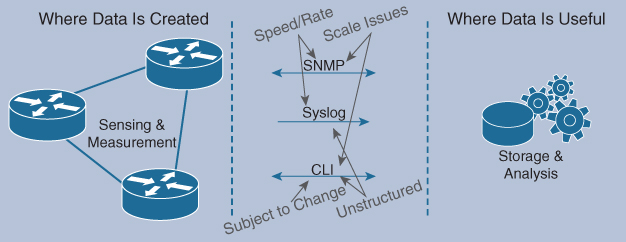
Figure 6-12 Traditional Management System Using SNMP, Syslog, and CLI
The traditional use of the pull model, where the client requests data from the network, does not scale when what you want is near real-time data.
Cisco NX-OS streaming telemetry allows you to push data off the device to a defined endpoint as JavaScript Object Notation (JSON) or using Google Protocol Buffers (GPB) at a much higher frequency and more efficiently, as shown in Figure 6-13.
![]()

Figure 6-13 Management System with Streaming Telemetry
Three simple steps are all that is required to configure telemetry:
Step 1. Set the format and destination to which the data is to be sent.
Step 2. Configure the data that is to be collected as part of the sensor group.
Step 3. Set the subscription between the sensor-group and the destination, along with the pace at which to send the data (in millseconds).
This data collected can be sent to the collector of your choice, be it an in-house tool, a commercial application such as Splunk, or a Cisco-provided solution such as the Data Center Network Manager (DCNM).
To help aid in the adoption and understanding of the capabilities of telemetry, Cisco provided a sample collector, which is available on Docker Hub. This receiver can take GPB data streamed from the network, parse it into JSON, which can then be forwarded to the database of your choice.
With this telemetry data, you can see network state and changes in near real-time, allowing easier and more timely visibility into your network, as shown in Figure 6-14.

Figure 6-14 Health Monitor Using Streaming Telemetry
Using a combination of open-source tools and well-understood industry formats, you can begin your journey with telemetry data on Cisco NX-OS.
Example 6-27 shows a cadence-based collection of show command data every 750 seconds to monitor system health.
Example 6-27 NX-OS Telemetry Configuration Example
switch(config)# telemetry
switch(config-telemetry)# destination-group 1
switch(conf-tm-dest)# ip address 172.27.247.72 port 60001 protocol gRPC encoding GPB
switch(conf-tm-dest)# sensor-group 1
switch(conf-tm-sensor# data-source NX-API
switch(conf-tm-sensor)# path “show system resources”
switch(conf-tm-sensor)# path “show version”
switch(conf-tm-sensor)# path “show environment power”
switch(conf-tm-sensor)# path “show environment fan”
switch(conf-tm-sensor)# path “show environment temperature”
switch(conf-tm-sensor)# path “show processes cpu”
switch(conf-tm-sensor)# path “show policy-map vlan”
switch(conf-tm-sensor)# path “show ip access-list test”
switch(conf-tm-sensor)# subscription 1
switch(conf-tm-sub)# dst-grp 1
switch(conf-tm-dest)# snsr-grp 1 sample-interval 750000
For security, SSL/TLS certificates can be used to encrypt all the data exchanged between the client and the server. Optional mechanisms are available for clients to provide certificates for mutual authentication.
A sample configuration, with encryption enabled, is shown in Example 6-28.
Example 6-28 NX-OS Telemetry with Encryption Configuration Example
This example creates a subscription that streams data every 5 seconds to destination IP 1.2.3.4 port 50003, and encrypts the stream using GPB encoding verified using the test.pem.
switch(config)# telemetry
switch(config-telemetry)# certificate /bootflash/test.pem foo.test.google.fr
switch(conf-tm-telemetry)# destination-group 100
switch(conf-tm-dest)# ip address 1.2.3.4 port 50003 protocol gRPC encoding GPB
switch(config-dest)# sensor-group 100
switch(conf-tm-sensor)# path <show command>
switch(conf-tm-sensor)# subscription 100
switch(conf-tm-sub)# snsr-grp 100 sample-interval 5000
switch(conf-tm-sub)# dst-grp 100
Example 6-29 shows telemetry data collector details.
Example 6-29 NX-OS Telemetry Status
switch# show telemetry data collector details
--------------------------------------------------------------------------------
Succ Collections      Failed Collections     Sensor Path
--------------------------------------------------------------------------------
150                     0                      <path>
! This command displays the statistic for the telemetry pipeline.
switch# show telemetry pipeline stats
Main Statistics:
    Timers:
        Errors:
            Start Fail        =     0

    Data Collector:
        Errors:
            Node Create Fail  =     0

    Event Collector:
        Errors:
            Node Create Fail  =     0    Node Add Fail     =     0
            Invalid Data      =     0
Queue Statistics:
    Request Queue:
        High Priority Queue:
            Info:
                Actual Size       =    50    Current Size      =     0
                Max Size          =     0    Full Count        =     0

            Errors:
                Enqueue Error     =     0    Dequeue Error     =     0

        Low Priority Queue:
            Info:
                Actual Size       =    50    Current Size      =     0
                Max Size          =     0    Full Count        =     0

            Errors:
                Enqueue Error     =     0    Dequeue Error     =     0

    Data Queue:
        High Priority Queue:
            Info:
                Actual Size       =    50    Current Size      =     0
                Max Size          =     0    Full Count        =     0

            Errors:
                Enqueue Error     =     0    Dequeue Error     =     0

        Low Priority Queue:
            Info:
                Actual Size       =    50    Current Size      =     0
                Max Size          =     0    Full Count        =     0

            Errors:
                Enqueue Error     =     0    Dequeue Error     =     0

! This command displays all configured transport sessions.

switch# show telemetry transport

Session Id      IP Address      Port       Encoding   Transport  Status
-----------------------------------------------------------------------------------
0               192.168.20.123   50001      GPB        gRPC       Connected
Network Assurance Concept
Digital transformation is rapidly accelerating because there are thousands of new applications, virtualized environments, and clouds. These applications can be hosted anywhere in the world. Building an enormous new data center with all network and security policies following those applications wherever they reside will be very challenging. The best approach is to build a new data center with network assurance and Cisco intent-based networking to address the new data center requirements.
Intent-based networking solutions enable conventional practices that require the alignment of manually derived individual network-element configurations to be replaced by controller-led and policy-based abstractions that easily enable you to express intent (desired outcome) and subsequently validate that the network is doing what you asked of it. Scale, agility, and security demands associated with digital transformation require that element-by-element network configuration be replaced by automated systemwide programming of network elements with consistent intent-based policies. Furthermore, the contextual analysis of data before, during, and after deployment enables continuous verification to help assure that the network is delivering the desired outcome and protection at any point in time. Continuous gathering of telemetry and other forms of data from a multitude of diverse sources provides a rich context of information to optimize a system and ensure it is secure.
The Cisco Network Assurance Engine solution provides continuous verification and analysis of the entire data center network, giving you confidence that your network is operating consistently with your intent. It combines mathematically accurate network models with codified Cisco domain knowledge to generate “smart events” that pinpoint deviations from intent and offer remediation recommendations.
Using comprehensive analysis spanning operator intent, controller policy, switch configurations, and data-plane state, the Network Assurance Engine helps you proactively detect network outages and security policy vulnerabilities before they impact business, reduces risk by predicting change impact, and rapidly determines the root cause of problems. With a unified network repository and compliance rules, the Network Assurance Engine simplifies audits and ensures compliance.
The Cisco Network Assurance Engine is the critical Intent Assurance pillar of Cisco’s vision for intent-based data center networks. Built on Cisco’s patented network verification technology, the Network Assurance Engine is a comprehensive intent-assurance solution that mathematically verifies the entire data center network for correctness. It gives you the confidence that you network is always operating consistently with your intent, even as it changes dynamically.
With the Cisco Network Assurance Engine, you can do the following:
• Predict the impact of changes: Proactively verify changes for correctness to drive increased change agility while significantly reducing risk of human error–induced network failures.
• Verify networkwide behavior: Continuously analyze and verify the dynamic state of the network against intent and policy to ensure connectivity and eliminate potential network outages and vulnerabilities before any business impact occurs.
• Assure network security policy and compliance: Assure network security policies and check for compliance against business rules to reduce security risk and achieve provable continuous compliance by policy and state.
The Cisco Network Assurance Engine achieves all of the above by reading the entire policy—every configuration, the networkwide state, and the operator’s intent—and building from these comprehensive and mathematically accurate models of network behavior. It then combines these models with more than 30 years of Cisco’s operational domain knowledge of networking to generate smart events that instantly pinpoint any deviations from intended behavior and suggest expert-level remediation recommendations. By providing this continuous verification and validation of the entire data center network, the Cisco Network Assurance Engine fundamentally transforms the operations paradigm from reactive to proactive, as shown in Figure 6-15.
![]()
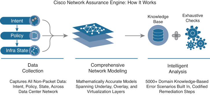
Figure 6-15 Cisco Network Assurance Engine
As the industry’s most comprehensive intent-assurance suite, the Cisco Network Assurance Engine ushers in an operational paradigm that promises to bring to networking the advantages of verification-driven, agile, proactive change management for network operations. The Network Assurance Engine brings together unique capabilities, including
• Most complete vision for intent-based networks in the industry: Architected from the ground up for seamless integration with the Cisco Application Centric Infrastructure (Cisco ACI) solution, delivering on the vision of closed-loop intent-based networks for data centers.
• Codified Cisco domain knowledge: Includes 5000+ built-in failure scenarios in the initial version, powering smart events with remediation steps.
• Deep policy controller integration: Assures controller policy and configurations, correlating with dynamic network state.
• Comprehensive analysis: Captures, analyzes, and correlates entire network state–switch configurations plus hardware data-plane state.
The Network Assurance Engine enables you to provide these business benefits:
• Increase change agility: Exhaustive verification-driven methodology to drive faster change approvals and elimination of human error.
• Avoid lost revenue and improve service-level agreements (SLAs): Deep, continuous fabric analysis and visibility to reduce outages and dramatically reduce the mean time to repair issues.
• Enhance operational maturity: Detailed DevNet runbooks to empower tier 1 and tier 2 network operation center teams and reduce escalations.
• Ensure network security: Complete network security policy analysis and visualization, detailed Ternary Content Addressable Memory (TCAM) optimization, and ability to check for compliance against business intent.
• Accelerate migrations: Day-zero configuration analysis and accelerated learning curve of the software-driven networking paradigm to reduce uncertainty in migration timelines.
Operational benefits to using the Network Assurance Engine include the following:
• Operator playbook: Smart events that precisely convey the diagnosis, cause, impact, and remediation of complex network issues in a context-specific human-readable manner.
• Codification of knowledge: Multiple years’ worth of Cisco Technical Assistance Center and autonomous system cross-customer domain knowledge codified for use.
• DVR audit trail: Complete record of historical configuration, along with state and assurance analysis data that is easily retrievable, searchable, sortable, and filterable.
• Offline analysis: Remote on-demand analysis of multiple fabrics available for customers.
• Ease of deployment: Seamless deployment using controller credentials with no additional sensors; deep linking with Cisco ACI fabric.
Exam Preparation Tasks
As mentioned in the section “How to Use This Book” in the Introduction, you have a couple of choices for exam preparation: the exercises here, Chapter 20, “Final Preparation,” and the exam simulation questions in the Pearson Test Prep software online.
Review All Key Topics
Review the most important topics in the chapter, noted with the key topic icon in the outer margin of the page. Table 6-16 lists a reference to these key topics and the page numbers on which each is found.
![]()
Table 6-16 Key Topics for Chapter 6

Memory Tables
Print a copy of Appendix C, “Memory Tables” (found on the companion website), or at least the section for this chapter, and complete the tables and lists from memory. Appendix D, “Memory Tables Answer Key,” also on the companion website, includes completed tables and lists to check your work.
Define Key Terms
Define the following key terms from this chapter, and check your answers in the Glossary.
basic input/output system (BIOS)
command-line interface (CLI)
Video Terminal 100 (VT100)
Nonvolatile random-access memory (NVRAM)
Dynamic Host Configuration Protocol (DHCP)
complex programmable logic device (CPLD)
field-programmable gate array (FPGA)
central processing unit (CPU)
Coordinated Universal Time (UTC)
generic routing encapsulation (GRE)
JavaScript Object Notation (JSON)
Google Protocol Buffers (GPB)
Transport Layer Security/Secure Sockets Layer (TLS/SSL)
service-level agreement (SLA)
Tool command language (Tcl)
in-service software upgrade (ISSU)
Software Maintenance Updates (SMU)
Graceful Insertion and Removal (GIR)
References
Cisco Nexus 5600 Series NX-OS Software Upgrade and Downgrade Guide, Release 7.3(5)N1(1): https://www.cisco.com/c/en/us/td/docs/switches/datacenter/nexus5600/sw/upgrade/735_N1_1/n5600_upgrade_downgrade_735_n1_1.html#pgfId-687951
Cisco Nexus 5600 Series NX-OS System Management Configuration Guide, Release 7.x: https://www.cisco.com/c/en/us/td/docs/switches/datacenter/nexus5600/sw/system_management/7x/b_5600_System_Mgmt_Config_7x.html
Cisco Nexus 7000 Series FPGA/EPLD Upgrade Release Notes, Release 8.x: https://www.cisco.com/c/en/us/td/docs/switches/datacenter/nexus7000/sw/epld/cisco_nexus7000_epld_rn_8x.html
Cisco Nexus 7000 Series NX-OS Software Upgrade and Downgrade Guide, Release 8.x: https://www.cisco.com/c/en/us/td/docs/switches/datacenter/nexus7000/sw/upgrade/guide/cisco_nexus7000_software_upgrade_and_downgrade_guide_8x.html
Cisco Nexus 7000 Series NX-OS System Management Configuration Guide: https://www.cisco.com/c/en/us/td/docs/switches/datacenter/nexus7000/sw/system-management/config/cisco_nexus7000_system-management_config_guide_8x.html
Cisco Nexus 7000 Series NX-OS Fundamentals Configuration Guide: https://www.cisco.com/c/en/us/td/docs/switches/datacenter/nexus7000/sw/fundamentals/config/cisco_nexus7000_fundamentals_config_guide_8x.html
Cisco Nexus 9000 Series NX-OS Software Upgrade and Downgrade Guide, Release 9.3(x): https://www.cisco.com/c/en/us/td/docs/switches/datacenter/nexus9000/sw/93x/upgrade/guide/b-cisco-nexus-9000-nx-os-software-upgrade-downgrade-guide-93x.html
Cisco Nexus 9000 Series NX-OS System Management Configuration Guide, Release 9.3(x): https://www.cisco.com/c/en/us/td/docs/switches/datacenter/nexus9000/sw/93x/system-management/b-cisco-nexus-9000-series-nx-os-system-management-configuration-guide-93x.html
Cisco Nexus 9000 Series NX-OS Fundamentals Configuration Guide, Release 9.3(x): https://www.cisco.com/c/en/us/td/docs/switches/datacenter/nexus9000/sw/93x/fundamentals/configuration/guide/b-cisco-nexus-9000-nx-os-fundamentals-configuration-guide-93x.html