
Chapter 8. Implement FCoE Unified Fabric
Simply defined, I/O consolidation is the ability to carry different types of traffic with different traffic characteristics and handling requirements over the same physical media. The most difficult challenge of I/O consolidation is to satisfy the requirements of different traffic classes within a single network. Because Fibre Channel is the dominant storage protocol in the data center, any viable I/O consolidation solution for storage must allow for transparent integration of the Fibre Channel model. Fibre Channel over Ethernet (FCoE) meets this requirement in part by encapsulating each Fibre Channel frame inside an Ethernet frame. The goal of FCoE is to provide I/O consolidation over Ethernet, allowing Fibre Channel and Ethernet networks to share a single, integrated infrastructure, thereby reducing network complexities in the data center. FCoE consolidates both storage-area networks (SANs) and Ethernet traffic onto one converged network adapter (CNA), eliminating the need for using separate host bus adapters (HBAs) and network interface cards (NICs).
This chapter covers the following key topics:
• FCoE Overview: This section discusses Ethernet enhancements including PFC, ETS, and DCBX, along with FCoE frame format, virtual Fibre Channel (VFC), FCoE elements, and port types. Later in the section, we discuss FCoE addressing and forwarding, FCoE Initialization Protocol (FIP), and the benefits of FCoE.
• FCoE Topology Options: This section discusses various FCoE topology options, including single-hop and multi-hop topologies.
• FCoE Implementations: This section discusses FCoE configuration on Cisco Nexus 7000 Series, 5000 Series, FCoE over FEX, and FCoE NPV configuration and verification.
“Do I Know This Already?” Quiz
The “Do I Know This Already?” quiz enables you to assess whether you should read this entire chapter thoroughly or jump to the “Exam Preparation Tasks” section. If you are in doubt about your answers to these questions or your own assessment of your knowledge of the topics, read the entire chapter. Table 8-1 lists the major headings in this chapter and their corresponding “Do I Know This Already?” quiz questions. You can find the answers in Appendix A, “Answers to the ‘Do I Know This Already?’ Quizzes.”
Table 8-1 “Do I Know This Already?” Section-to-Question Mapping”

Caution
The goal of self-assessment is to gauge your mastery of the topics in this chapter. If you do not know the answer to a question or are only partially sure of the answer, you should mark that question as wrong for purposes of the self-assessment. Giving yourself credit for an answer you correctly guess skews your self-assessment results and might provide you with a false sense of security.
1. Which of the following statements is TRUE regarding Enhanced Transmission Selection (ETS)?
a. ETS automatically discovers and negotiates DCB capabilities between the NIC and switch.
b. ETS manages end-to-end congestion.
c. ETS enables multiple traffic types to share the same link.
d. ETS manages bandwidth between different types of traffic on the same link.
2. What is the Ethertype of FCoE and FIP frames?
a. FCoE = 0x8906; FIP = 0x8914
b. FCoE = 0x8906; FIP = 0x8916
c. FCoE = 0x8914; FIP = 0x8906
d. FCoE = 0x8916; FIP = 0x8906
3. Which action is performed in the FCF discovery phase in the FIP process?
a. CNA broadcasts a solicitation to find FCF to log in to. Broadcasts go out on the FCoE VLAN.
b. CNA begins normal FC data commands using Ethertype 0x8906.
c. CNA performs fabric login using FLOGI or FLOGI with NPV FDISC.
d. An end device (CNA) broadcasts a request for FCoE VLAN. The request occurs on the native VLAN.
4. Which of the following statements is CORRECT regarding the virtual Fibre Channel interface? (Choose three answers.)
a. Each virtual Fibre Channel interface must be bound to an FCoE-enabled Ethernet interface.
b. Each virtual Fibre Channel interface can be associated with multiple VSANs.
c. Any VSAN with associated virtual Fibre Channel interfaces must be mapped to a dedicated FCoE-enabled VLAN.
d. The Fibre Channel portion of FCoE is configured with the help of a virtual Fibre Channel (vFC) interface.
5. Which of the following is not a FCoE single-hop topology?
a. FCoE direct-attached topology
b. FCoE remote-attached topology
c. FCoE FEX topology
d. FCoE remote-attached FEX topology
6. Which of the following commands disables LAN traffic on an FCoE link?
a.
   switch(config)# interface Ethernet 2/1
   switch(config-if)# shutdown lan
b.
   switch(config)# interface Ethernet 2/1
   switch(config-if)# lan shutdown
c.
   switch(config)# interface Ethernet 2/1
   switch(config-if)# shutdown switchport
d.
   switch(config)# interface Ethernet 2/1
   switch(config-if)# switchport shutdown
7. Which of the following statements are CORRECT regarding FCoE NPV? (Choose three answers.)
a. FCoE NPV implements FIP snooping as an extension to the NPV function while retaining the traffic-engineering, vsan-management, administration, and troubleshooting aspects of NPV.
b. Connectivity from an FCoE NPV bridge to the FCF is supported only over point-to-multipoint links.
c. From a control plane perspective, FCoE NPV performs proxy functions toward the FCF and the hosts in order to load-balance logins from the hosts evenly across the available FCF uplink ports.
d. An FCoE NPV bridge is VSAN-aware and capable of assigning VSANs to the hosts.
Foundation Topics
FCoE Overview
A typical data center has two separate networks: one for Ethernet and one for Fibre Channel storage. These networks are physically and logically separated from each other, as shown on the left in Figure 8-1. Here, a SAN leverages dual fabric with multipathing failover initiated by the client, and a LAN leverages single fully meshed fabric with higher levels of component redundancy. Both networks have a redundant pair of switches at each layer, which results in increased CAPEX and OPEX as well as reduced business functionality.


Figure 8-1 Traditional LAN and SAN Infrastructure (Left); Converged LAN and SAN Infrastructure (Right)
The consolidation of I/O traffic in the data center brings the Fibre Channel and Ethernet networks into a single integrated infrastructure, as shown on the right in Figure 8-1. This results in decreased CAPEX and OPEX. An access switch in the consolidated topology is Fibre Channel over Ethernet Forwarder (FCF). Dual fabrics are still deployed for redundancy.
Servers used to have three types of NICs: Ethernet NICs for LAN traffic, management traffic, backup traffic, and so on; host channel adapter (HCA) for Inter-Process Communication (IPC) traffic; and HBAs for Fibre Channel/storage traffic, as shown in Figure 8-2. With the development of FCoE, converged network adapters (CNAs) were introduced; they can handle all the previous three types of traffic over single high-speed 10G links, resulting in a lesser number of interfaces for servers.
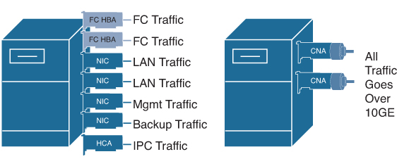
Figure 8-2 Converged Network Adapter
Fibre Channel over Ethernet (FCoE) allows Fibre Channel traffic to be encapsulated over a physical Ethernet link. FCoE frames use a unique Ethertype so that FCoE traffic and standard Ethernet traffic can be carried on the same link.
Classic Ethernet is a best-effort protocol; in the event of congestion, Ethernet will discard packets, relying on higher-level protocols to provide retransmission and other reliability mechanisms. Fibre Channel traffic requires a lossless transport layer; because it is a data storage protocol, it is unacceptable to lose a single data packet. Native Fibre Channel implements a lossless service at the transport layer using a buffer-to-buffer credit system.
For FCoE traffic, the Ethernet link must provide a lossless service. Ethernet links on Cisco Nexus devices provide two mechanisms to ensure lossless transport for FCoE traffic: link-level flow control (LLFC) and priority-based flow control (PFC). For FCoE, PFC is recommended.
IEEE 802.3x link-level flow control allows a congested receiver to signal the far end to pause the data transmission for a short period of time. The pause functionality is applied to all the traffic on the link.
The priority flow control feature applies pause functionality to specific classes of traffic on the Ethernet link. For example, PFC can provide lossless service for the FCoE traffic and best-effort service for the standard Ethernet traffic. PFC can provide different levels of service to specific classes of Ethernet traffic. We discuss these enhancements to Ethernet protocol in detail in the next section.
Ethernet Enhancements
The T11 organization’s FC-BB-5 standard defines FCoE and also defines running FC over other media types. The IEEE 802.1 organization facilitates FCoE by defining enhancements to Ethernet. These enhancements fall under the DCB umbrella, specifically, three enabling standards for Ethernet to support FCoE:
1. Priority-based flow control (PFC)
2. Enhanced Transmission Selection (ETS)
3. Data Center Bridging Exchange (DCBX)
Figure 8-3 identifies the T11 and IEEE standards.

Figure 8-3 T11 and IEEE 802.1 FCoE Standards
Priority-Based Flow Control (PFC)
PFC is defined in IEEE 802.1Qbb. Link sharing is critical to I/O consolidation. For link sharing to succeed, large bursts from one traffic type must not affect other traffic types, large queues of traffic from one traffic type must not starve other traffic types’ resources, and optimization for one traffic type must not create large latency for small messages of other traffic types. The Ethernet pause mechanism can be used to control the effects of one traffic type over another.
![]()
PFC creates eight separate virtual links, each belonging to a CoS priority value, on the physical link and allows any of these links to be paused and restarted independently. This approach can enable the network to create a no-drop class of service for an individual virtual link that can coexist with other traffic types on the same interface. In native FC, the network is designed not to drop traffic (lossless). PFC can enable Ethernet to support FC by providing a lossless fabric. Figure 8-4 shows the eight virtual data lanes on a single wire that make up PFC. One virtual lane of data (for example, FC) can be paused while the remaining lanes continue to transmit.
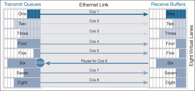
Figure 8-4 Priority-Based Flow Control (PFC)
The Ethernet frames that are sent by the switch to the adapter may include the IEEE 802.1Q tag. This tag includes a field for the class of service (CoS) value used by the priority-based flow control (PFC). The IEEE 802.1Q tag also includes a virtual LAN (VLAN) field.
Enhanced Transmission Selection (ETS)
![]()
ETS is defined in IEEE 802.1Qaz. PFC can create eight distinct virtual link types on a physical link, and it can be advantageous to have different traffic classes defined within each virtual link. Traffic within the same PFC IEEE 802.1p class can be grouped together yet treated differently within each group. ETS provides prioritized processing based on bandwidth allocation, low latency, or best effort, resulting in per-group traffic class allocation.
Extending the virtual link concept, the network interface card (NIC) provides virtual interface queues: one for each traffic class. Each virtual interface queue is accountable for managing its allotted bandwidth for its traffic group but has flexibility within the group to dynamically manage the traffic. For example, virtual link 3 for the IP class of traffic may have a high-priority designation and a best effort within that same class, with the virtual link 3 class sharing a percentage of the overall link with other traffic classes. ETS allows differentiation among traffic of the same priority class, thus creating a priority group. The capability to apply differentiated treatment to different traffic within the same priority class is enabled by implementing ETS.
Figure 8-5 shows three classes of traffic sharing the same 10-Gbps ETS-enabled connection with the following predefined percentages:
• Server Cluster Traffic: 30 percent
• Storage Traffic: 30 percent
• LAN Traffic: 40 percent
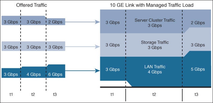
Figure 8-5 Enhanced Transmission Selection (ETS)
In Figure 8-5
• During interval T1, Server Cluster Traffic, Storage Traffic, and LAN Traffic each use 3-Gbps bandwidth, hence not saturating the 10-Gbps link.
• During interval T2, when the offered traffic reaches the 10-Gbps limit of the connection, ETS is activated to distribute the traffic with the predefined percentages (30, 30, and 40 for Server Cluster Traffic, Storage Traffic, and LAN Traffic, respectively).
• During interval T3, Server Cluster Traffic only requires 2 Gbps of traffic, thus enabling another class of traffic (LAN Traffic) to share the unused bandwidth.
Data Center Bridging Exchange (DCBX)
![]()
DCBX is defined in IEEE 802.1Qaz. DCBX is a discovery and capability exchange protocol that IEEE DCBs use to discover peers and exchange configuration information between DCB-compliant bridges (see Figure 8-6). The following parameters can be exchanged with DCBX:
• Priority groups in ETS
• PFC
• Congestion notification
• Applications
• Logical link-down
• Network interface virtualization
Figure 8-6 Data Center Bridging Exchange
DCBX allows network devices to advertise their identities and capabilities over the network. It enables end devices to pick up proper configuration from the network and for switches to verify proper configuration.
The DCBX protocol is an extension of the Link Layer Discovery Protocol (LLDP). DCBX endpoints exchange request and acknowledgment messages. For flexibility, parameters are coded in a type-length-value (TLV) format. DCBX runs on the physical Ethernet link between the Cisco Nexus device and the CNA. By default, DCBX is enabled on Ethernet interfaces. When an Ethernet interface is brought up, the switch automatically starts to communicate with the CNA. During the normal operation of FCoE between the switch and the CNA, DCBX provides link-error detection. DCBX is also used to negotiate capabilities between the switch and the CNA and to send configuration values to the CNA.
The CNAs that are connected to a Cisco Nexus device are programmed to accept the configuration values sent by the switch, allowing the switch to distribute configuration values to all attached CNAs. This reduces the possibility of configuration errors and simplifies CNA administration.
DCBXP is enabled by default when you enable LLDP. When LLDP is enabled, DCBXP can be enabled or disabled using the [no] lldp tlv-select dcbxp command. DCBXP is disabled on ports where LLDP transmit or receive is disabled.
You can enable LLDP on each FCoE switch by issuing the feature lldp command. On the Cisco Nexus 7000, LLDP is enabled when the FCoE feature set is installed (in the storage VDC). You cannot disable LLDP while the FCoE feature is installed.
The switch and CNA exchange capability information and configuration values. Cisco Nexus devices support the following capabilities:
• FCoE: If the CNA supports FCoE capability, the switch sends the IEEE 802.1p CoS value to be used with FCoE packets.
• PFC: If the adapter supports PFC, the switch sends the IEEE 802.1p CoS values to be enabled with PFC.
• Priority group type, length, and values (TLV)
• Ethernet logical link up and down signal
• FCoE logical link up and down signal for pre-FIP CNAs
The following rules determine whether the negotiation results in a capability being enabled:
• If a capability and its configuration values match between the switch and the CNA, the feature is enabled.
• If a capability matches, but the configuration values do not match, the following occurs:
• If the CNA is configured to accept the switch configuration value, the capability is enabled using the switch value.
• If the CNA is not configured to accept the switch configuration value, the capability remains disabled.
• If the CNA does not support a DCBX capability, that capability remains disabled.
• If the CNA does not implement DCBX, all capabilities remain disabled.
FCoE Frame Format
FCoE is implemented by encapsulating an FC frame in an Ethernet packet with the dedicated Ethertypes 0x8906(FCoE) and 0x8914(FIP). An FC frame, encapsulated inside the FCoE header, consists of 24 bytes of headers and up to 2112 bytes of data. The encapsulated FC frame has all the standard headers, which allow it to be passed to the storage network without further modification.
Figure 8-7 details the FC encapsulation into Ethernet frames.
![]()


Figure 8-7 FCoE Frame Format
In the FCoE header with Ethertype 0x8906, the first 48 bits consists of the destination MAC address, and the next 48 bits consist of the source MAC address. The 32-bit IEEE 802.1Q tag defines the VLAN. FCoE has its own Ethertype as designated by the next 16 bits followed by the 4-bit version field. The next 100 bits are reserved; they pad the FCoE frame to the IEEE 802.3 minimum packet length of 64 bytes and are followed by the 8-bit start-of-frame. The actual Fibre Channel frame is followed by the start-of-frame. The 8-bit end-of-frame delimiter is followed by 24 reserved bits. Lastly, the frame ends with 32 bits dedicated to the FCS function that provides error detection functionality for the Ethernet frame.
FIP is encapsulated in an Ethernet packet with a dedicated Ethertype: 0x8914. The packet has a 4-bit version field, as shown in Figure 8-8. Along with the source and destination MAC addresses, the FIP packet also contains an FIP operation code and an FIP operation subcode. Table 8-2 describes the FIP operation codes and subcodes.
![]()

Figure 8-8 FIP Frame Format
Table 8-2 FIP Operation Codes and Subcodes

Virtual Fibre Channel (VFC)
In a native FC storage-area network (SAN), physical FC switches and end devices (such as hosts with host bus adapters [HBAs]) are connected with fiber cable. The FC protocol runs natively on the SAN, and both the switches and end devices communicate through it.
With FCoE, that FC SAN is overlaid onto a physical Ethernet network, creating a VFC SAN running over Ethernet. In the previous section, we discussed the enhancements to Ethernet needed to facilitate this. In addition to these enhancements, a new process is needed on Cisco Nexus switches to support FC. This process is known as FCoE Manager or fcoe_mgr. The fcoe_mgr process controls all the FCoE components and configuration. The fcoe_mgr process is started by installing the FCoE feature set. Virtual SANs (VSANs) are then associated with designated FCoE VLANs and bind virtual Fibre Channel (vFC) interfaces to physical Ethernet interfaces. FCoE configuration is discussed later in this chapter.
With FCoE, HBAs are replaced with CNAs. CNAs enable converged I/O by supporting both FC and classical Ethernet data traffic on the same Ethernet wire. CNAs, along with proper drivers on the host end device, support FCoE.
Figure 8-9 is an illustration of a VSAN over Ethernet.
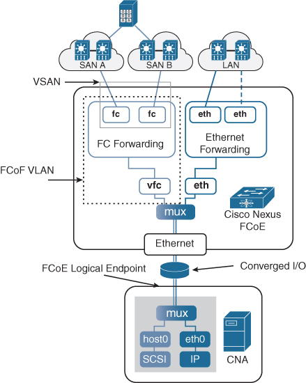
Figure 8-9 Virtual FC over Ethernet
The Fibre Channel portion of FCoE is configured with the help of a virtual Fibre Channel (vFC) interface. In FCoE, there are only physical Ethernet interfaces. You don’t have any physical Fibre Channel interfaces, so you actually need to create a logical instance of those Fibre Channel interfaces. To do that, you create a virtual Fibre Channel interface and bind it to both a VSAN that it’s associated with and a physical Ethernet interface on a switch, so that when that interface comes up, the vFC comes up. Logical Fibre Channel features can be configured on virtual Fibre Channel interfaces.
![]()
Following are some guidelines that you must follow when creating a virtual Fibre Channel interface:
• Each virtual Fibre Channel interface must be bound to an FCoE-enabled Ethernet interface. FCoE is supported on 10-Gigabit Ethernet interfaces.
• Each virtual Fibre Channel interface is associated with only one VSAN.
• Any VSAN with associated virtual Fibre Channel interfaces must be mapped to a dedicated FCoE-enabled VLAN.
• FCoE is not supported on private VLANs.
The Ethernet interface to which you bind the virtual Fibre Channel interface must be a trunk port. The FCoE VLAN that corresponds to the virtual Fibre Channel’s VSAN must be in the allowed VLAN list and must not be configured as the native VLAN of the trunk port. Also, the Ethernet interface must be configured as portfast using the spanning-tree port type edge trunk command.
Example 8-1 shows how to configure the VLAN on a physical Ethernet address, create virtual Fibre Channel interface 6, bind vFC 6 to the physical Ethernet interface, enable associated VLAN 600, and map VLAN 600 to VSAN 6.
Example 8-1 Virtual Fibre Channel Interface Configuration
switch# configure terminal
switch(config)# interface ethernet 1/2
switch(config-if)# switchport mode trunk
switch(config-if)# switchport trunk allowed vlan 1,600
switch(config)# interface vfc 6
switch(config-if)# bind interface ethernet 1/2
switch(config-if)# exit
switch(config)# vlan 600
switch(config-vlan)# fcoe vsan 6
switch(config-vlan)# exit
switch(config)# vsan database
switch(config-vsan)# vsan 6 interface vfc 6
FCoE Elements and Port Types
The FCoE standard defines two types of endpoints: FCoE Ethernet Nodes (ENodes) and Fibre Channel Forwarders (FCFs). Figure 8-10 shows a simplified version of an ENode. An ENode (also called a CNA adapter) is a Fibre Channel HBA implemented within an Ethernet NIC. The data-forwarding component that handles FC frame encapsulation/decapsulation is called an FCoE Link EndPoint (LEP). An FCoE LEP is a virtual FC interface mapped onto the physical Ethernet interface. An FCoE controller is the functional entity that performs the FIP and instantiates VN_Port/FCoE_LEP pairs. We discuss the FCoE Initialization Protocol (FIP) in the next section.

Figure 8-10 Simplified ENode
Note
Only second-generation CNAs support the FCoE control plane protocol called FIP. FIP support is required to build certain types of topologies in FCoE; for example, use of FEXs in the FCoE topology requires FIP support.
Figure 8-11 shows a simplified version of the FCoE switch. FCF is the forwarding entity inside an FCoE switch. An FCF switch is one that actually contains both a Fibre Channel switch and an Ethernet switch—for example, the Cisco Nexus 5000 Series switch. A Cisco MDS switch with FCoE module installed can act as an FCF switch also. The FCF processes the Fibre Channel logins and consumes one domain ID. FCF performs the encapsulation and decapsulation of the FCoE frames and forwards the FCoE traffic based on Fibre Channel information that the frames contain.
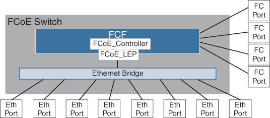
Figure 8-11 Simplified FCoE Switch
ENodes present virtual FC interfaces in the form of VN_Ports, which can establish FCoE virtual links with FCFs’ VF_Ports, as shown in Figure 8-12. FCFs present virtual FC interfaces in the form of VF_Ports or VE_Ports; a VF_Port establishes FCoE virtual links with a CNA’s VN_Port or FCoE NPV’s VNP_Port, and VE_Ports enable FCFs to establish FCoE virtual links with other FCFs. These interface types have their equivalents in native Fibre Channel’s N_Ports, F_Ports, and E_Ports. A virtual fabric (VF) port in an FCoE network acts as a fabric port that connects to a peripheral device (host or disk) operating as an VN_port. A VF_port can be attached to only one VN_port. A virtual expansion (VE) port acts as an expansion port in an FCoE network and can connect to multiple FCoE switches together in the network.
![]()

Figure 8-12 FC and FCoE Switch Port Types
Ethernet devices communicate using a MAC address, whereas Fibre Channel devices communicate using FCIDs. Because FCoE switches support both Ethernet and Fibre Channel, it needs to able to translate between them. Because Ethernet uses a 48-bit MAC address and Fibre Channel uses a 24-bit FCID, a direct translation between them is not possible.
FCoE Addressing and Forwarding
![]()
FCoE uses a Fabric Provided MAC Address (FPMA) for SAN traffic. The ENode still gets a 24-bit FCID. FPMA is built by concatenating a 24-bit FCoE MAC address prefix (FC-MAP), ranging from 0x0E-FC-00 to 0x0E-FC-FF, to the 24-bit FCID, as shown in Figure 8-13. Being able to build a unique MAC address for the ENode directly from its FCID saves the switch from having to maintain a table that associates FCID and MAC addresses.
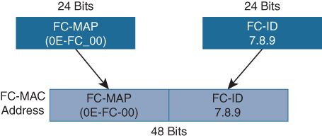
Figure 8-13 Fabric-Provided MAC Address (FPMA)
The FC-MAP range was introduced so that different values can be assigned to different SANs. For example, SAN A would be associated with 0x0EFC00 and SAN B with 0x0EFC01. This additional configuration ensures the uniqueness of the produced FPMA in the whole network. FC-MAPs are different for different SANs, FCIDs are uniquely assigned within a SAN, and the resulting FC-MAP and FCID are unique across the different SANs in the entire network.
Figure 8-14 shows a Fibre Channel frame traversing native Fibre Channel SAN and FCoE SAN. For simplicity, only the header information is displayed in the figure. The FCoE forwarding in Figure 8-14 can be summarized in the following steps:
1. The Fibre Channel N_port on the storage array sends out the FC frame to the VN port on the CNA adapter with Source FCID (S_ID) as 7.1.1 and Destination FCID (D_ID) as 1.1.1. The frame is switched by the first Fibre Channel Switch.
2. Because the destination ID (D_ID) is not in FC domain 7 of the receiving switch, the switch forwards the frame to the port associated with the shortest path to the destination, using the FSPF algorithm. The Fibre Channel switch with domain ID 7 sends the frame to the FCoE switch with domain ID 3.
3. The FCoE switch with domain 3 receives the frame. Because the destination ID (D_ID) is not in the FC domain 3 of the receiving switch, the switch forwards the frame to the port associated with the shortest path to the destination, using the FSPF algorithm. In this case, the frame will be transmitted to the FCoE-enabled Ethernet fabric. The FC frame is encapsulated inside an Ethernet frame with source MAC address (MAC A) of VE_port of switch with FC domain 3 and destination MAC address (MAC B) of VE_port of switch with FC domain 1.
4. When the frame arrives at the FCoE switch with the FC domain 1, the frame is decapsulated, and the switch determines that the FC frame destination is within its domain. The FC frame is reencapsulated with a source MAC address of MAC B and a destination MAC address of MAC C. The frame is then transmitted out to the appropriate port where MAC C and FCID 1.1.1 are connected.
5. When the HBA adapter with MAC C receives the frame, it decapsulates the frame and accepts the FC frame with FCID 1.1.1

Figure 8-14 FCoE Forwarding
FCoE Initialization Protocol (FIP)
FCoE Initialization Protocol (FIP) is the FCoE control protocol responsible for establishing and maintaining Fibre Channel virtual links between pairs of FCoE devices (ENodes or FCFs). During the virtual link establishment phase, FIP first discovers FCoE VLANs and remote virtual FC interfaces; then it performs virtual link initialization functions (fabric login [FLOGI] and fabric discovery [FDISC], or exchange link parameters [ELP]) similar to their native Fibre Channel equivalents. After the virtual link is established, Fibre Channel payloads can be exchanged on the virtual link, and FIP remains in the background to perform virtual link maintenance functions; it continuously verifies reachability between the two virtual FC interfaces on the Ethernet network, and it offers primitives to delete the virtual link in response to administrative actions to that effect.
FIP aims to establish virtual FC links between VN_Ports and VF_Ports (ENode to FCF), as well as between pairs of VE_Ports (FCF to FCF), because these are the only legal combinations supported by native Fibre Channel fabrics. This section focuses on FIP in the context of virtual FC links between VN_Ports and VF_Ports.
![]()
Cisco NX-OS supports the T11-compliant FIP on Cisco Nexus devices. FIP is used to perform device discovery, initialization, and link maintenance. FIP performs the following protocol steps:
• FIP VLAN discovery: FIP discovers the FCoE VLAN that will be used by all other FIP protocols and the FCoE encapsulation for Fibre Channel payloads on the established virtual link. FIP VLAN discovery occurs in the native VLAN used by the initiator or target to exchange Ethernet traffic. The FIP VLAN discovery protocol is the only FIP protocol running on the native VLAN; all other FIP protocols run on the discovered FCoE VLANs.
• FIP discovery: When an FCoE device is connected to the fabric, it sends out a Discovery Solicitation message. A Fibre Channel Forwarder (FCF) or a switch responds to the message with a Solicited Advertisement that provides an FCF MAC address to use for subsequent logins.
• FCoE virtual link instantiation: FIP defines the encapsulation of FLOGI, fabric discovery (FDISC), logout (LOGO), and exchange link parameter (ELP) frames, along with the corresponding reply frames. The FCoE devices use these messages to perform a fabric login.
• FCoE virtual link maintenance: FIP periodically sends maintenance messages between the switch and the CNA to ensure the connection is still valid. This is referred to as the FCoE Keepalive (FKA).
Figure 8-15 shows a typical FIP protocol exchange resulting in the establishment of a virtual link between an ENode’s VN_Port and an FCF’s VF_Port.
![]()
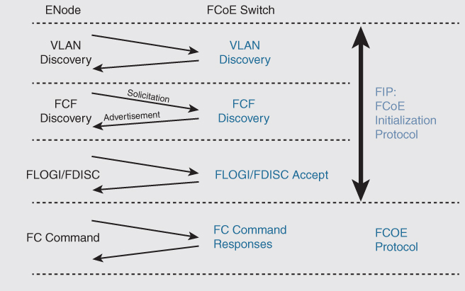
Figure 8-15 FCoE Initialization Protocol (FIP)
The CNA initiates an FIP VLAN request, broadcasting to destination MAC 01:10:18:01:00:02. This well-known MAC address is referred to as the ALL-FCF-MACs address, meaning FCoE-enabled switches will recognize and respond to it. Keep in mind that FIP uses Ethertype 0x8914. In this step, the CNA requests the FCoE VLAN. The VLAN request from the host should be received on the native VLAN. The native VLAN cannot be an FCoE VLAN.
The CNA next performs an FIP discovery by looking for an FCF switch to log in to. The CNA broadcasts again to the All-FCF-MACs address. This request, however, is transmitted on the FCoE VLAN that was learned from the previous request. In this discovery, the CNA provides information about itself, such as the maximum FCoE frame size it supports, its World Wide Name (WWN), and that it supports the Fabric Provided MAC Address (FPMA).
The switch advertises its capabilities. The advertisement contains the virtual fabric ID (VSAN), the switch FC MAP ID, and the FC Keepalive (FKA) period. The total frame size in the advertisement equals the maximum FCoE frame size the CNA sent in its discovery. The switch pads the Advertisement frame to ensure it matches what the CNA expects, and this will confirm the network path indeed supports full FC frame sizes (encapsulated in Ethernet).
Now that the CNA has a valid FCF that will support fabric logins, it initiates the FLOGI. In the screen image shown in Figure 8-15, the Ethertype is still 0x8914 (FIP). The rest of the frame contains standard FC FLOGI information.
The switch accepts the CNA’s FLOGI. This is the last step for the FIP VFC instantiation process and Ethertype 0x8914. All communication after this FLOGI Accept will be Ethertype 0x8906, which is the FCoE’s data plane.
Table 8-3 summarizes the FIP process.
![]()
Table 8-3 FIP Virtual Instantiation Summary

Benefits of FCoE
![]()
I/O consolidation in the fabric using FCoE provides several benefits. The benefits are as follows:
• Reduction in the number of adapters and network infrastructure devices
• Reduction in the number of cables:
• Allows economical blend of inexpensive copper and longer-link optical technologies
• Reduces cable installation expenses
• Significantly reduces the number of long cables
• Can increase server density if server deployment is impeded by cable bulk or airflow concerns
• Reduces the possibility of air dams in the data center
• Reduces cable maintenance and provisioning concerns in the data center
• Reduction in the amount of power used
• Reduction in space used due to switch equipment rack occupancy
• Reduction in server height due to fewer add-in card slot requirements if servers are I/O bound
• Redeployment of power and space savings to provisioning of additional servers, extending the life of the data center
• Interoperation with existing SANs; management of SANs remains constant
• No Stateful Gateway requirement; simply maps FC traffic onto lossless Ethernet
FCoE Topology Options
FCoE supported topologies can be broadly classified into two groups:
• FCoE single-hop topology
• FCoE multi-hop topology
FCoE Single-Hop Topology
Three single-hop solutions are possible when FCoE is deployed using Cisco Nexus switches:
• FCoE direct-attached topology: The host is directly connected to the first-hop converged access switch.
• FCoE FEX topology: A FEX is deployed between the server and the first hop converged access switch.
• FCoE remote-attached topology: A server is connected to a non-FCF switch that acts as an FCoE passthrough.
FCoE Direct-Attached Topology
In the topology shown in Figure 8-16, a CNA is directly attached to the FCF, and FCoE extends from the CNA to the FCF and then is broken out to Native FC and Ethernet. Trunking is not required on the host driver because all FCoE frames are tagged by the CNA. A VLAN can be dedicated for every virtual fabric in the SAN. FIP discovers the FCoE VLAN and signals it to the hosts. Because FIP uses native VLAN, you should not use it for FCoE VLANs. FCoE VLANs are mostly pruned on pure Ethernet links. If you are using MST, generally three instances are defined: one for Ethernet VLAN and one for each SAN fabric VLAN.

Figure 8-16 Direct-Attached Topology
Figure 8-16 shows a host connected to two FCFs (A and B). Three logical topologies in the figure are independent of each other: the first one for native Ethernet LAN using VLAN 10, the second one for Fabric A using VSAN 2, and the third and final one for Fabric B using VSAN 3. VSAN 2 is carried over VLAN 20, and VSAN 3 is carried over VLAN 30. The converged Ethernet between the host and the FCFs provides transport for both native Ethernet and Fibre Channel traffic.
The host can be connected to FCFs using vPC for improved resiliency, as shown in Figure 8-17. However, this might disrupt SAN traffic because SAN A traffic might leak to SAN B using a vPC peer-link and vice versa. Therefore, FCoE VLANs and FIP Ethertype are not allowed to cross the vPC peer-link although the Ethernet VLAN can cross the vPC peer-link.
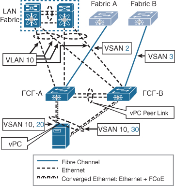
Figure 8-17 Direct-Attached Topology with vPC
FCoE FEX Topology
FCoE FEX topology is another variant of single-hop topology. In this topology, you extend the FCoE edge by using FEXs. A host can be connected to FEXs using either individual links or vPC. For vPC connectivity, native Ethernet traffic uses both the uplinks, but Fibre Channel traffic uses a single link and does not participate in vPC. FEXs, in turn, are connected to the northbound FCFs using either static pinning of individual links or using a single-homed port channel, as shown in Figure 8-18.

Figure 8-18 FCoE FEX Topology
Note
Not all FEXs support the preceding FCoE setup. Refer to the capability of different FEXs by using the appropriate data sheet for the FEX model. Also, only second-generation CNAs support FEX FCoE design because FIP is a requirement for this design.
FCoE Remote-Attached Topology
FCoE remote-attached topology is another variant of single-hop topology. In this topology, the host is connected to FCFs via FCoE passthrough switches, as shown in Figure 8-19. The virtual link between the VN port and VF port is established through the Ethernet path that crosses one or more passthrough switches.
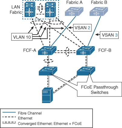
Figure 8-19 FCoE Remote-Attached Topology
Passthrough switches make forwarding decisions using Ethernet semantics and are not capable of forwarding Fibre Channel frames. Passthrough switches pose a security risk because someone can intercept the traffic through such a switch. To overcome the security concerns, you can either configure FIP snooping or a manual access control list. FIP snooping locks down the forwarding path from a CNA to FCFs using automatic configuration of ACLs. You can also configure access control lists manually to stop an attacker from spoofing MAC addresses although this results in more administrative overhead.
FCoE Multi-Hop Topology
Multi-hop FCoE makes use of VE ports to expand the FCoE fabric. VE ports are similar to E ports in the Fibre Channel world. Two VE ports are connected using either a single link or port channel in a point-to-point fashion, as shown in Figure 8-20. For each of the FCF-connected Ethernet interfaces, a vFC interface is created and binds to the Ethernet interface.

Figure 8-20 FCoE Multi-Hop Topology
In FCoE multi-hop topology, the usual traffic is from north-south from the initiator to the target, but east-west traffic could be an issue in this design. Because the FCoE infrastructure is increased from the edge access layer switch to multi-hops, the advantage of this topology is the decreased number of cables between servers and switches.
FCoE Implementations
Cisco Nexus devices support FCoE implementation including the 2000 Series FEX (selected models) and the Cisco Nexus 5000, 7000, 7700, 6000, and 9000 Series switches. Cisco MDS 9000 Series multilayer switches also support FCoE implementation.
In the Cisco Nexus 7000/7700 Series switches, each F Series module that runs FCoE requires an FCoE license. Also, FCoE does not require an additional VDC and is enabled in the storage VDC by default. On Cisco Nexus 5000 Series switches, FCoE capability is included in the Storage Protocol Services License, which needs to be activated by entering the feature fcoe command. FCoE is enabled on Cisco MDS Series switches by default although Cisco MDS series switches are mostly used for Fibre Channel connectivity. The Cisco NX-OS software supports FCoE with 10-Gigabit and 40-Gigabit Ethernet interfaces. Because the implementation of FCoE is a little bit different in different NX-OS devices, we look at Cisco Nexus 7000 Series, Cisco Nexus 5000 Series, and Cisco Nexus 2000 Series implementations separately.
FCoE Configuration on Cisco Nexus 7000 Series Switches
Let’s first look into the configuration steps required to configure FCoE on Cisco Nexus 7000 Series switches.
Example 8-2 shows configuration tasks that need to be performed while you are configuring FCoE on Cisco Nexus 7000 Series switches.
![]()
Example 8-2 Sample FCoE Configuration on Nexus 7000 Series Switches
Step 1: Preparing the Switch for Configuring FCoE

! Firstly, you will need to install FCoE feature set and associate an FCoE license with an FCoE module to configure FCoE. You need one license for each module configured for FCoE. Then enable no drop queue for FCoE class.

switch# configure terminal
switch(config)# install feature-set fcoe
switch(config)# feature lldp
switch(config)# license fcoe module 2
switch(config)# system qos
switch(config-sys-qos)# service-policy type network-qos default-nq-7e-policy


Step 2: Creating and configuring Storage VDC

! Create a dedicated storage VDC and enable storage features in a storage VDC. You do not need to allow the feature-set or enable it in the storage VDC because this process is handled automatically for a storage VDC.  Also you will need to allocate interfaces to the storage VDC as a dedicated FCoE port. You must allocate all interfaces in the port group. You must configure these interfaces in switchport trunk mode as Spanning Tree Protocol (STP) edge ports. Also ensure that you have allocated the FCoE VLAN range.

switch(config)# vdc fcoe type storage
switch(config-vdc)# allocate interface ethernet 2/1
switch(config-vdc)# allocate fcoe-vlan-range 10-30

switch(config)# interface ethernet 2/1
switch(config-if)# switchport mode trunk
switch(config-if)# spanning-tree port type edge trunk

! Enable LLDP feature and unshut the FCoE ports on storage VDC.

switch# switchto vdc fcoe type storage
switch-fcoe# configure terminal
switch-fcoe(config)# feature lldp
switch-fcoe(config)# interface ethernet 2/1
switch-fcoe(config-if)# no shutdown


Step 3: Configuring FCoE VLANs and Virtual Fibre Channel Interfaces

! A unique, dedicated VLAN must be configured at every converged access switch to carry traffic for each virtual fabric (VSAN) in the SAN (for example, VLAN 200 for VSAN 200, VLAN 300 for VSAN 300, and so on). If you enable MST, you must use a separate Multiple Spanning Tree (MST) instance for FCoE VLANs. In following example we allow VLAN 200 which will later be mapped to FCoE VSAN 200


switch-fcoe(config)# interface ethernet 2/1
switch-fcoe(config-if)# switchport trunk allowed vlan 1,200

switch-fcoe(config)# vsan database
switch-fcoe(config-vsan-db)# vsan 200

switch-fcoe(config)# vlan 200
switch-fcoe(config-vlan)# fcoe vsan 200

! To use FCoE, you must first create Virtual Fibre Channel (vFC) interfaces. Then, you must bind the VFC interfaces to physical interfaces before FCoE can be used.

switch-fcoe(config)# interface vfc 2
switch-fcoe(config-if)# switchport mode e
switch-fcoe(config-if)# bind interface ethernet 2/1

! Configure the association between the VSAN and virtual Fibre Channel interface or virtual Fibre Channel port channel.

switch-fcoe(config)# vsan database
switch-fcoe(config-vsan-db)# vsan 200 interface vfc 2
switch-fcoe(config-vsan-db)# exit
Miscellaneous FCoE Configuration
DCBX allows the switch to send a LAN Logical Link Status (LLS) message to a directly connected CNA. To disable LAN traffic on an FCoE link, enter the shutdown lan command to send an LLS-Down message to the CNA. This command causes all VLANs on the interface that are not enabled for FCoE to be brought down. If a VLAN on the interface is enabled for FCoE, it continues to carry SAN traffic without any interruption.
switch(config)# interface Ethernet 2/1
switch(config-if)# shutdown lan
The FCoE switch advertises its priority. The priority is used by the CNAs in the fabric to determine the best switch to connect to. You can configure the global fabric priority using following command. The default value is 128. The range is from 0 (higher) to 255 (lower).
switch-fcoe(config)# fcoe fcf-priority 42
You can configure the interval for Fibre Channel fabric advertisement on the switch using the following command:
switch-fcoe(config)# fcoe fka-adv-period 8
The VFID check verifies that the VSAN configuration is correct on both ends of a VE link. You can turn off the VFID check for VE ports to allow VE loopback configuration between two VE ports on the same switch.
switch-fcoe(config)# fcoe veloopback
FCoE Configuration on Cisco Nexus 5000 Series Switches
Because there is no concept of storage VDC on Cisco Nexus 5000 Series switches, the configuration is a little bit different when it comes to FCoE configuration on these switches. Example 8-3 shows a sample FCoE configuration on Cisco Nexus 5000 Series switches.
Example 8-3 shows configuration tasks that need to be performed while you are configuring FCoE on Cisco Nexus 5000 Series switches.
![]()
Example 8-3 Sample FCoE Configuration on Nexus 5000 Series Switches
Step 1: Configure QoS

! Before enabling FCoE on a Cisco Nexus device, you must attach the pre-defined FCoE policy maps to the type qos, type network-qos, and type queuing policy maps.

switch(config)# system qos
switch(config-sys-qos)# service-policy type {network-qos | qos |queuing } [input | output ] fcoe-default policy-name

! The previous command specifies the default FCoE policy map to use as the service policy for the system. There are four pre-defined policy-maps for FCoE.

switch(config-sys-qos)# service-policy type queuing input fcoe-default-in-policy
switch(config-sys-qos)# service-policy type queuing output fcoe-default-out-policy
switch(config-sys-qos)# service-policy type qos input fcoe-default-in-policy
switch(config-sys-qos)# service-policy type network-qos fcoe-default-nq-policy

! You can configure the default Ethernet system class to support the jumbo MTU using following commands

switch(config)# policy-map type network-qos jumbo
switch(config-pmap-nq)# class type network-qos class-fcoe
switch(config-pmap-c-nq)# pause no-drop
switch(config-pmap-c-nq)# mtu 2158
switch(config-pmap-nq)# class type network-qos class-default
switch(config-pmap-c-nq)# mtu 9216
switch(config-pmap-c-nq)# exit
switch(config-pmap-nq)# exit

switch(config)# system qos
switch(config-sys-qos)# service-policy type network-qos jumbo

Step 2: Enable the FCoE and LLDP feature
switch# configure terminal
switch(config)# feature fcoe
switch(config)# feature lldp

Step 3: Enable the associated VLAN and map the VLAN to a VSAN.

switch(config)# vlan 200
switch(config-vlan)# fcoe vsan 2
switch(config-vlan)# exit

Step 4: Configure the VLAN on a physical Ethernet interface.

switch# configure terminal
switch(config)# interface ethernet 1/4
switch(config-if)# spanning-tree port type edge trunk
switch(config-if)# switchport mode trunk
switch(config-if)# switchport trunk allowed vlan 1,200
switch(config-if)# exit

Step 5: Create a virtual Fibre Channel interface and bind it to a physical Ethernet interface.

switch(config)# interface vfc 4
switch(config-if)# bind interface ethernet 1/4
switch(config-if)# exit

Step 6: Associate the virtual Fibre Channel interface to the VSAN.

switch(config)# vsan database
switch(config-vsan)# vsan 2 interface vfc 4
switch(config-vsan)# exit
Other miscellaneous configurations such as disabling LAN traffic on an FCoE link, configuring fabric-priority, and setting the advertisement interval are the same as discussed for the Cisco Nexus 7000 Series configuration.
FCoE over FEX
If you are using FEX in between an FCF and a host, then the additional configuration steps are as shown in Example 8-4.
Example 8-4 shows configuration tasks that need to be performed while you are configuring FCoE over FEX on Cisco Nexus 5000 Series switches.
![]()
Example 8-4 Sample FCoE over FEX Configuration on Nexus 5000 Series Switches
Step 1: Enable FCoE and LLDP features, and FEX for FCoE.

switch(config)# feature fcoe
switch(config)# feature lldp
switch(config)# fex 200
switch(config-fex)# fcoe

Step 2: Configure switch physical interface in fex-fabric mode and associate the fex.

switch(config)# interface Ethernet 2/1
switch(config-if)# switchport mode fex-fabric
switch(config-if)# fex associate 200

Step 3: Configure the VLAN on the Physical Interface

switch(config)# interface Ethernet 200/1/1
switch(config-if)# switchport mode trunk
switch(config-if)# switchport trunk native vlan 24
switch(config-if)# switchport trunk allowed vlan 24, 200
switch(config-if)# spanning-tree port type edge trunk

Step 4: Associate FCoE VSAN to FCoE VLAN.

switch(config)# vlan 200
switch(config-vlan)# fcoe vsan 200

Step 5: Create a virtual Fibre Channel interface and bind it to a physical Ethernet interface.

switch(config)# interface vfc200
switch(config-if)# bind interface Ethernet 200/1/1
switch(config-if)# no shutdown

Step 6: Associate the virtual Fibre Channel interface to the VSAN.

switch(config)# vsan database
switch(config-vsan)# vsan 200 interface vfc 200
FCoE NPV
FCoE NPV is supported on the Cisco Nexus devices. It functions similarly to traditional FCoE. The FCoE NPV feature is an enhanced form of FIP snooping that provides a secure method to connect FCoE-capable hosts to an FCoE-capable FCoE forwarder (FCF) switch.
The FCoE NPV feature provides the following benefits:
• FCoE NPV does not have the management and troubleshooting issues that are inherent to managing hosts remotely at the FCF.
• FCoE NPV implements FIP snooping as an extension to the NPV function while retaining the traffic-engineering, vsan-management, administration, and troubleshooting aspects of NPV.
• FCoE NPV and NPV together allow communication through FC and FCoE ports at the same time. This provides a smooth transition when moving from FC to FCoE topologies.
From a control plane perspective, FCoE NPV performs proxy functions toward the FCF and the hosts in order to load-balance logins from the hosts evenly across the available FCF uplink ports. An FCoE NPV bridge is VSAN-aware and capable of assigning VSANs to the hosts.
VSANs from the hosts must be created, and for each VSAN, a dedicated VLAN must also be created and mapped. The mapped VLAN is used to carry FIP and FCoE traffic for the corresponding VSAN. The VLAN-VSAN mapping must be configured consistently in the entire fabric.
For each host directly connected over Ethernet interfaces on the FCoE NPV bridge, a virtual Fibre Channel (vFC) interface must be created and bound to the Ethernet interface. By default, the vFC interface is configured in the F mode (VF port).
Connectivity from an FCoE NPV bridge to the FCF is only supported over point-to-point links. These links can be individual Ethernet interfaces or members of an Ethernet port channel interface. For each FCF-connected Ethernet interface, a vFC interface must be created and bound to the Ethernet interface. These vFC interfaces must be configured as VNP ports. On the VNP port, an FCoE NPV bridge emulates an FCoE-capable host with multiple ENodes, each with a unique ENode MAC address. By default, the VNP port is enabled in trunk mode.
Example 8-5 shows configuration tasks that need to be performed while you are configuring FCoE NPV on Cisco Nexus 5000 Series switches on the sample topology shown in Figure 8-21.
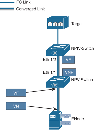
Figure 8-21 Sample Topology for FCoE NPV
![]()
Example 8-5 Sample FCoE NPV Configuration on Nexus 5000 Series Switches
Step 1: Enable FCoE NPV

! You can enable FCoE NPV using the feature fcoe-npv command.

npv-switch# configure terminal
npv-switch(config)# feature fcoe-npv


Step 2: Enable FCoE QoS

npv-switch(config)# system qos
npv-switch(config-sys-qos)# service-policy type qos input fcoe-default-in-policy
npv-switch(config-sys-qos)# service-policy type queuing input fcoe-default-in-policy
npv-switch(config-sys-qos)# service-policy type queuing output fcoe-default-out-policy
npv-switch(config-sys-qos)# service-policy type network-qos fcoe-default-nq-policy

Step 3: Configuring VLAN to VSAN mapping

npv-switch(config)# vsan database
npv-switch(config-vsan-db)# vsan 50
npv-switch(config-vsan-db)# vlan 50
npv-switch(config-vlan)# fcoe vsan 50


Step 4: VNP Port configuration

npv-switch(config)# int e1/1
npv-switch(config-if)# switchport mode trunk
npv-switch(config-if)# switchport trunk allowed vlan 50
npv-switch(config-if)# no shut

! Create a vFC port and bind it to an Ethernet port. Set the port mode to NP and bring up the port.

npv-switch# config t
npv-switch(config)# interface vfc 20
npv-switch(config-if)# switchport mode NP
npv-switch(config-if)# bind interface ethernet 1/1
npv-switch(config-if)# switchport trunk allowed vsan 50
npv-switch(config-if)# no shutdown

Step 5: VF Port configuration

! A similar configuration must be applied to NPIV side of the link. The primary difference is that the vFC is configured for the VF mode and NPIV is enabled.

npiv-switch(config)# feature npiv
npiv-switch(config)# interface Ethernet1/2
npiv-switch(config-if)# switchport
npiv-switch(config-if)# switchport mode trunk
npiv-switch(config-if)# switchport trunk allowed vlan 50
npiv-switch(config-if)# no shutdown

! Create a vFC port and bind it to an Ethernet port. Set the port mode to F and bring up the port.

npiv-switch(config-if)# interface vfc20
npiv-switch(config-if)# switchport mode F
npiv-switch(config-if)# bind interface Ethernet1/2
npiv-switch(config-if)# switchport trunk allowed vsan 50
npiv-switch(config-if)# no shutdown
FCoE Verification
The verification commands are the same for Cisco Nexus switches and Cisco MDS switches. We discuss some of the verification commands in this section. You can find a list of useful FCoE verification commands in Table 8-4.
Example 8-6 shows some verification commands along with output. Note that the output in Example 8-6 does not reflect any of the previous configuration examples and is provided only to acquaint you with various verification commands.
Example 8-6 FCoE Verification Commands
! To verify that the FCoE capability is enabled, use the show fcoe command.

switch# show fcoe
Global FCF details
        FCF-MAC is 00:0d:ec:6d:95:00
        FC-MAP is 0e:fc:00
        FCF Priority is 128
        FKA Advertisement period for FCF is 8 seconds
! To display the FCoE database, use the show fcoe database command

switch# show fcoe database
----------------------------------------------------------------------
INTERFACE    FCID        PORT NAME                 MAC ADDRESS
----------------------------------------------------------------------
vfc3         0x490100    21:00:00:1b:32:0a:e7:b8   00:c0:dd:0e:5f:76

! To display the FCoE settings for an interface, use the show interface <interface number> fcoe command.

switch# show interface ethernet 1/37 fcoe
Ethernet1/37 is FCoE UP
    vfc3 is Up
        FCID is 0x490100
        PWWN is 21:00:00:1b:32:0a:e7:b8
        MAC addr is 00:c0:dd:0e:5f:76

! To display a virtual Fibre Channel interface bound to an Ethernet interface, use the show interface vfc <vfc-id> command.

switch# show interface vfc 3
vfc3 is up
    Bound interface is Ethernet1/37
    Hardware is Virtual Fibre Channel
    Port WWN is 20:02:00:0d:ec:6d:95:3f
    Admin port mode is F, trunk mode is on
    snmp link state traps are enabled
    Port mode is F, FCID is 0x490100
    Port vsan is 931
    1 minute input rate 0 bits/sec, 0 bytes/sec, 0 frames/sec
    1 minute output rate 0 bits/sec, 0 bytes/sec, 0 frames/sec
      0 frames input, 0 bytes
        0 discards, 0 errors
      0 frames output, 0 bytes
        0 discards, 0 errors
    Interface last changed at Thu May 21 04:44:42 2019

! To display the mapping between the VLANs and VSANs on the switch, use the show vlan fcoe command.

switch# show vlan fcoe
VLAN      VSAN      Status
--------  --------    --------
15           15       Operational
20           20       Operational
25           25       Operational
30           30       Non-operational

! To verify VSAN membership of Virtual Interface, use the show vsan <vsan-id> membership command.

switch# show vsan 11 membership
vsan 11 interfaces:
    fc1/47            fc1/48         vfc1011


! To verify the information about the NPV FLOGI session, use the show npv flogi-table command.


switch# show npv flogi-table
------------------------------------------------------------------------------------------------
SERVER                                                                               EXTERNAL
INTERFACE  VSAN   FCID        PORT NAME                  NODE NAME                   INTERFACE
------------------------------------------------------------------------------------------------
vfc1        20    0x670000    21:01:00:1b:32:2a:e5:b8    20:01:00:1b:32:2a:e5:b8     fc2/6
Total number of flogi = 1.

! To verify the status of the NPV configuration including information about VNP ports, use the show npv status command.

switch# show npv status

npiv is enabled

disruptive load balancing is disabled

External Interfaces:
====================
  Interface:  fc2/5, State: Trunking
        VSAN:    1, State: Up
        VSAN:  200, State: Up
        VSAN:  400, State: Up
        VSAN:   20, State: Up
        VSAN:  100, State: Up
        VSAN:  300, State: Up
        VSAN:  500, State: Up, FCID: 0xa10000
  Interface:  fc2/6, State: Trunking
        VSAN:    1, State: Up
        VSAN:  200, State: Up
        VSAN:  400, State: Up
        VSAN:   20, State: Up
        VSAN:  100, State: Up
        VSAN:  300, State: Up
        VSAN:  500, State: Up, FCID: 0xa10001
  Interface: vfc90,  State: Down
  Interface: vfc100, State: Down
  Interface: vfc110, State: Down
  Interface: vfc111, State: Down
  Interface: vfc120, State: Down
  Interface: vfc130, State: Trunking
        VSAN:    1, State: Waiting For VSAN Up
        VSAN:  200, State: Up
        VSAN:  400, State: Up
        VSAN:  100, State: Up
        VSAN:  300, State: Up
        VSAN:  500, State: Up, FCID: 0xa10002

  Number of External Interfaces: 8

Server Interfaces:
==================
  Interface:   vfc1, VSAN:   20, State: Up
  Interface:   vfc2, VSAN: 4094, State: Down
  Interface:   vfc3, VSAN: 4094, State: Down
  Interface: vfc5000, VSAN: 4094, State: Down
  Interface: vfc6000, VSAN: 4094, State: Down
  Interface: vfc7000, VSAN: 4094, State: Down
  Interface: vfc8090, VSAN: 4094, State: Down
  Interface: vfc8191, VSAN: 4094, State: Down

  Number of Server Interfaces: 8
Table 8-4 summarizes the NX-OS CLI commands that are related to FCoE configuration and verification.
![]()
Table 8-4 Summary of NX-OS CLI Commands for FCoE Configuration and Verification


Example 8-7 begins the configuration and verification of FCoE on the sample topology shown in Figure 8-22. This example shows configuration for N5K because after configuring the link between the parent switch (N5K) and FEX as FEX fabric, you basically consider interfaces on FEX as they are on the parent switch.
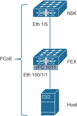
Figure 8-22 Sample Topology for FCoE Configuration and Verification
Example 8-7 FCoE Configuration and Verification
! Verifying if FCoE and lldp feature is enabled on N5K
N5K# show feature | in fcoe|lldp
fcoe         1         enabled
fcoe-npv     1         disabled
lldp         1         enabled

! Verifying if appropriate FCoE aware QoS is enabled
N5K# show policy-map type network-qos

  Type network-qos policy-maps
  ===============================

  policy-map type network-qos default-nq-policy
    class type network-qos class-default

      mtu 1500
  policy-map type network-qos fcoe-default-nq-policy
    class type network-qos class-fcoe

      pause no-drop
      mtu 2158
    class type network-qos class-default

      mtu 1500
  policy-map type network-qos fcoe-default-nq-policy-jumbo
    class type network-qos class-fcoe

      pause no-drop
      mtu 2158
    class type network-qos class-default

      mtu 9216

! Verifying the status of VSAN 11
N5K# show vsan 11
vsan 11 information
         name:VSAN0011  state:active
         interoperability mode:default
         loadbalancing:src-id/dst-id/oxid
         operational state:up

! Enabling FCoE for FEX
N5K# configure terminal
Enter configuration commands, one per line.  End with CNTL/Z.
N5K(config)# fex 100
N5K(config-fex)# fcoe

! Assigning VSAN 11 to FCoE VLAN 1011
N5K(config-fex)# vlan 1011
N5K(config-vlan)# fcoe vsan 11

! Configuring Physical Interface on N5K connected to FEX
N5K(config-vlan)# interface Ethernet1/5
N5K(config-if)# switchport mode fex-fabric
N5K(config-if)# fex associate 100

 Configuring FEX interface populated on N5K
N5K(config-if)# interface Ethernet100/1/1
N5K(config-if)# switchport mode trunk
N5K(config-if)# switchport trunk native vlan 27
N5K(config-if)# switchport trunk allowed vlan 27, 1011

! Configuring Virtual Interface and binding Physical Interface to it
N5K(config-if)# interface vfc1011
N5K(config-if)# bind interface ethernet 100/1/1
N5K(config-if)# switchport mode F
N5K(config-if)# switchport trunk allowed vsan 11
Warning: This command will remove all VSANs currently being trunked and trunk only the specified VSANs.
Do you want to continue? (y/n) [n] y
N5K(config-if)# no shutdown

! Binding Virtual Interface to VSAN 11
N5K(config-if)# vsan database
N5K(config-vsan-db)# vsan 11 interface vfc1011
N5K(config-vsan-db)# end

! Verifying status of FCoE VLAN
N5K(config-if)# show vlan fcoe

Original VLAN ID        Translated VSAN ID      Association State
-----------------       -------------------     ------------------
      1011                       11                 Operational


! Verifying VSAN membership of Virtual Interface
N5K# show vsan 11 membership
vsan 11 interfaces:
    fc1/47            fc1/48            san-port-channel 7  vfc1011

! Verifying FEX interface FCoE status connected to the host.
N5K# show interface ethernet 100/1/1 fcoe
    vfc1011 is Up
Ethernet100/1/1 is FCoE UP
        FCID is 0x470000
        PWWN is 20:00:00:25:b5:10:70:10
        MAC addr is d4:c9:3c:fe:d2:be

! Verifying the status of vFC interface
N5K# show interface vfc 1011
vfc1011 is trunking
    Bound interface is Ethernet100/1/1
    Hardware is Ethernet
    Port WWN is 23:f2:8c:60:4f:2d:de:ff
    Admin port mode is F, trunk mode is on
    snmp link state traps are enabled
    Port mode is TF
    Port vsan is 11
    Trunk vsans (admin allowed and active) (11)
    Trunk vsans (up)                                      (11)
    Trunk vsans (isolated)                              ()
    Trunk vsans (initializing)                         ()
    1 minute input rate 256 bits/sec, 32 bytes/sec, 0 frames/sec
    1 minute output rate 272 bits/sec, 34 bytes/sec, 0 frames/sec
      17 frames input, 1904 bytes
        0 discards, 0 errors
      18 frames output, 2020 bytes
        0 discards, 0 errors
    last clearing of “show interface” counters Sun Aug  4 22:23:42 2019
    Interface last changed at Sun Aug  4 22:23:42 2019

! Verifying fabric login status of the host using vFC interface
N5K# show flogi database
-------------------------------------------------------------------------------------
INTERFACE    VSAN    FCID       PORT NAME                   NODE NAME
-------------------------------------------------------------------------------------
vfc1011       11     0x470000   20:00:00:25:b5:10:70:10     21:00:00:25:b5:10:70:10

Total number of flogi = 1.
Exam Preparation Tasks
As mentioned in the section “How to Use This Book” in the Introduction, you have a couple of choices for exam preparation: the exercises here, Chapter 20, “Final Preparation,” and the exam simulation questions in the Pearson Test Prep software online.
Review All Key Topics
Review the most important topics in the chapter, noted with the key topic icon in the outer margin of the page. Table 8-5 lists a reference to these key topics and the page numbers on which each is found.
![]()
Table 8-5 Key Topics for Chapter 8

Memory Tables
Print a copy of Appendix C, “Memory Tables” (found on the companion website), or at least the section for this chapter, and complete the tables and lists from memory. Appendix D, “Memory Tables Answer Key,” also on the companion website, includes completed tables and lists to check your work.
Define Key Terms
Define the following key terms from this chapter, and check your answers in the Glossary.
host bus adapter (HBA)
Fibre Channel over Ethernet N-port Virtualization (FCoE-NPV)
Fibre Channel over Ethernet N-Port ID Virtualization (FCoE-NPIV)
data center bridging (DCB)
priority-based flow control (PFC)
IEEE 802.1Qbb
Enhanced Transmission Selection (ETS)
IEEE 802.1Qaz
Data Center Bridging Exchange (DCBX)
type-length-value (TLV)
Fibre Channel over Ethernet (FCoE)
converged network adapter (CNA)
multi-hop FCoE
Inter-Process Communication (IPC)
Fabric Shortest Path First (FSPF)
References
Cisco MDS 9000 Series FCoE Configuration Guide, Release 8.x: https://www.cisco.com/c/en/us/td/docs/switches/datacenter/mds9000/sw/8_x/config/fcoe/cisco_mds9000_fcoe_config_guide_8x.html
Cisco Nexus 5600 Series NX-OS Fibre Channel over Ethernet Configuration Guide, Release 7.x: https://www.cisco.com/c/en/us/td/docs/switches/datacenter/nexus5600/sw/fcoe/7x/b_5600_FCoE_Config_7x.html
End-to-End FCoE Design Guide: https://www.cisco.com/c/en/us/products/collateral/storage-networking/mds-9700-series-multilayer-directors/guide-c07-732733.html
Fibre Channel over Ethernet (FCoE) Configuration and Troubleshooting Guide: https://www.cisco.com/c/dam/en/us/products/collateral/storage-networking/mds-9700-series-multilayer-directors/guide-c07-733622.pdf
Evaluating Multi-hop FCoE: https://www.cisco.com/c/en/us/td/docs/solutions/Enterprise/Data_Center/VMDC/tech_eval/mFCoEwp.html
Cisco Unified Fabric: Enable the Data Center Network White Paper: https://www.cisco.com/c/en/us/solutions/collateral/data-center-virtualization/unified-fabric/white_paper_c11-704054.html
FCoE Initiation Protocol White Paper: https://www.cisco.com/c/en/us/products/collateral/switches/nexus-7000-series-switches/white_paper_c11-560403.html
Relevant Cisco Live Presentations: https://www.ciscolive.com
Cisco Nexus 5000 Series NX-OS FCoE Operations Guide, Release 5.1(3)N1(1): https://www.cisco.com/c/en/us/td/docs/switches/datacenter/nexus5000/sw/operations/fcoe/513_n1_1/ops_fcoe.html
Single and Multi Switch Designs with FCoE: https://www.snia.org/sites/default/education/tutorials/2012/fall/networking/ChadHintz_Single_Multi_Switch_Designs_with_FCoE_v7.pdf
Cisco Nexus 7000 Series FCoE Configuration Guide 8.x: https://www.cisco.com/c/en/us/td/docs/switches/datacenter/nexus7000/sw/fcoe/config/cisco_nexus7000_fcoe_config_guide_8x.html
Unified Fabric White Paper—Fibre Channel over Ethernet (FCoE): https://www.cisco.com/c/en/us/td/docs/solutions/Enterprise/Data_Center/UF_FCoE_final.html
Gustavo A. A. Santana, Data Center Virtualization Fundamentals. (Indianapolis: Cisco Press, 2014)
Cisco Nexus 5600 Series NX-OS SAN Switching Configuration Guide, Release 7.x: https://www.cisco.com/c/en/us/td/docs/switches/datacenter/nexus5600/sw/san_switching/7x/b_5600_SAN_Switching_Config_7x.html