
Chapter 7. Implement Fibre Channel
The main purpose of data centers is to provide the resources required to run applications and securely store data. As enterprises of every size move to digitize their businesses and adapt to new cloud-native workloads while preserving support for well-established applications, they need to rely on a storage network with no compromises. Most enterprise applications count on relational databases and block storage to host their data. In this context, Fibre Channel networking devices are the preferred choice for connecting computational resources to data repositories in the form of disk arrays and tape libraries. Even today, with a variety of file- and object-based storage solutions on the market and the block-based alternative offered by Small Computer System Interface over IP (iSCSI) technology, almost all financial institutions and most Fortune 500 companies rely on Fibre Channel, sometimes in combination with its derivative Fibre Channel over Ethernet (FCoE) protocol, as their trusted storage networking infrastructure, capable of functioning with almost no downtime.
This chapter covers the following key topics:
• Fibre Channel Basics: This section discusses Fibre Channel topologies, port types, addressing, and switch fabric initialization. This section also discusses device registration, FLOGI, and FCNS databases.
• CFS: This section discusses CFS features, CFS fabric lock, CFSoIP, and CFSoFC concepts, along with CFS Merge and CFS Regions concepts.
• VSAN: This section discusses VSAN features, attributes, advantages, Dynamic Port VSAN Membership (DPVM), and VSAN Trunking concepts.
• SAN Port Channels: This section discusses types of SAN port channels, port channel load balancing, and port channel modes.
• Zoning: This section discusses zoning features, zone enforcement, full and active zone set, Autozone, zone merge, smart zoning, and enhanced zoning concepts.
• Device Alias: This section discusses device alias features, modes, and distribution and compares zone aliases and device aliases.
• NPIV and NPV: This section discusses the concepts of NPIV and NPV and includes a configuration example.
“Do I Know This Already?” Quiz
The “Do I Know This Already?” quiz enables you to assess whether you should read this entire chapter thoroughly or jump to the “Exam Preparation Tasks” section. If you are in doubt about your answers to these questions or your own assessment of your knowledge of the topics, read the entire chapter. Table 7-1 lists the major headings in this chapter and their corresponding “Do I Know This Already?” quiz questions. You can find the answers in Appendix A, “Answers to the ‘Do I Know This Already?’ Quizzes.”
Table 7-1 “Do I Know This Already?” Section-to-Question Mapping”

Caution
The goal of self-assessment is to gauge your mastery of the topics in this chapter. If you do not know the answer to a question or are only partially sure of the answer, you should mark that question as wrong for purposes of the self-assessment. Giving yourself credit for an answer you correctly guess skews your self-assessment results and might provide you with a false sense of security.
1. Which of the following is not a phase in the switched fabric initialization process?
a. Fabric reconfiguration
b. FCID allocation
c. Domain ID distribution
d. FCIP allocation
e. Principal switch (PS) selection
2. How is the principal switch selected during the fabric initialization process?
a. The lowest run-time priority is considered the highest priority.
b. The highest run-time priority is considered the highest priority.
c. The highest switch WWN is considered the highest priority.
d. The highest port WWN is considered the lowest priority.
3. Which of the following are CORRECT regarding the fabric login (FLOGI) process? (Choose two answers.)
a. FLOGI happens between the N port and an F port.
b. FLOGI happens between two N ports.
c. The N port sends the FLOGI request to the well-known directory service address 0xfffffc.
d. The N port sends the FLOGI request to the well-known fabric login server address 0xfffffe.
4. Which of the following statement is NOT correct regarding CFS?
a. CFS is a client/server protocol.
b. CFS uses a proprietary SW_ILS (0x77434653) protocol for all CFS packets.
c. Applications that use CFS are completely unaware of the lower layer transport.
d. The N port virtualization feature on Cisco NX-OS uses the CFS infrastructure.
5. Which of the following are CFS modes of distribution? (Choose three answers.)
a. Coordinated distributions
b. Unrestricted coordinated distributions
c. Uncoordinated distributions
d. Unrestricted uncoordinated distributions
6. Which of the following statements is NOT correct regarding VSANs?
a. Multiple VSANs cannot share the same physical topology.
b. The same Fibre Channel identifiers (FCIDs) can be assigned to a host in another VSAN.
c. Events causing traffic disruptions in one VSAN are contained within that VSAN and are not propagated to other VSANs.
d. VSAN 1 cannot be deleted, but it can be suspended.
7. What is the maximum number of VSANs that can be configured on a switch?
a. 128
b. 256
c. 512
d. 1024
8. Which of the following ports will NOT form a SAN port channel?
a. E ports and TE ports
b. F ports and NP ports
c. E ports and F ports
d. TF ports and TNP ports
9. Which of the following is NOT CORRECT regarding Active mode of SAN port channels? (Choose two answers.)
a. In Active mode, a port channel protocol negotiation is performed with the peer ports.
b. In Active mode, when you add or modify a port channel member port configuration, you must explicitly disable (shut) and enable (no shut) the port channel member ports at either end.
c. Active mode is the default mode in SAN port channels.
d. You must explicitly configure this mode.
10. Which of the following statements is NOT CORRECT regarding zones?
a. Devices can belong to only one zone at a time.
b. Members in a zone can access each other; members in different zones cannot access each other.
c. Zones can vary in size.
d. If zoning is activated, any device that is not in an active zone (a zone that is part of an active zone set) is a member of the default zone.
11. Zone members can be defined using which of the following criteria? (Choose three answers.)
a. Port World Wide Name (pWWN)
b. IPv4 address
c. FCIP address
d. FCID
12. Which of the following statements is CORRECT regarding the device alias feature?
a. The device alias information is dependent on the VSAN configuration.
b. The device alias configuration and distribution are dependent on the zone server and the zone server database.
c. The device alias application uses the Cisco Fabric Services (CFS) infrastructure to enable efficient database management and distribution.
d. A device alias name is restricted to 68 alphanumeric characters.
13. What happens when you commit the changes made to the pending database of the device alias?
a. The pending database content keeps a separate copy along with effective database content.
b. The pending database is emptied of its contents.
c. The fabric lock is implemented.
d. The pending database is not distributed to the switches in the fabric, and the effective database on those switches is overwritten with the new changes.
14. Once the NPV edge switch registers itself with the NPV core switch (NPIV), the NPV edge switch converts all subsequent FLOGIs from end devices to which message type?
a. NPV FLOGI
b. FDISCs
c. PLOGI
d. PLRI
Foundation Topics
Fibre Channel Basics
Fibre Channel (FC) is a high-speed data transfer protocol providing in-order, lossless delivery of raw block data, primarily used to connect computer data storage to servers. The lossless delivery of a raw data block is achieved based on a credit mechanism known as buffer-to-buffer credits, which we discuss later in this chapter. Fibre Channel typically runs on optical fiber cables within and between data centers but can also run on copper cabling. We will discuss copper cabling options in the next chapter when we dig deep into the FCoE protocol. Fibre Channel networks form a switched fabric because they operate in unison as one big switch. Here we set the stage for the Fibre Channel switched fabric initialization process after discussing various Fibre Channel topologies and port types.
Fibre Channel Topologies
It is common practice in SAN environments to build two separate, redundant physical fabrics (Fabric A and Fabric B) in case a single physical fabric fails. In the design of SANs, most environments fall into three types of topologies within a physical fabric: single-tier (collapsed-core), two-tier (core-edge design), and three-tier (edge-core-edge design).
• Collapsed-core topology: Within the single-tier design, servers are connected to the core switches. Storage devices are also connected to one or more core switches, as shown in Figure 7-1. Core switches provide storage services. It has single management per fabric and is mostly deployed for small SAN environments.

Figure 7-1 Collapsed-Core Topology
The main advantage of this topology is the degree of scalability offered at a very efficient port usage. The collapsed-core design aims to offer very high port density while eliminating a separate physical layer of switches and their associated ISLs.
The only disadvantage of the collapsed-core topology is its scale limit relative to the core-edge topology. While the collapsed-core topology can scale quite large, the core-edge topology should be used for the largest of fabrics. However, to continually scale the collapsed-core design, you could convert the core to a core-edge design and add another layer of switches.
• Core-edge topology: Within the two-tier design, servers connect to the edge switches, and storage devices connect to one or more core switches, as shown in Figure 7-2. This allows the core switch to provide storage services to one or more edge switches, thus servicing more servers in the fabric. The inter-switch links (ISLs) will have to be designed so that the overall fabric maintains both the fan-out ratio of servers to storage and the overall end-to-end oversubscription ratio. High availability is achieved using two physically separate, but identical, redundant SAN fabrics.
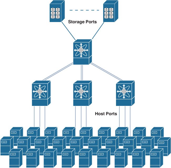
Figure 7-2 Core-Edge Topology
In the design of a core-edge topology, a major trade-off is made between three key characteristics of the design. The first trade-off is the overall effective port density that can be used to connect hosts or storage devices. For a given number of switches in a core-edge design, the higher the effective port density, typically the higher ISL oversubscription from the edge layer to the core layer. The second characteristic is the oversubscription of the design. Oversubscription is a natural part of any network topology because the nature of a SAN is to “fan out” the connectivity and I/O resources of storage devices. However, the higher the oversubscription of the design, the more likely congestion may occur, thereby impacting a wide scope of applications and their I/O patterns. The third characteristic that ties these other two together is cost. The basic principle suggests the higher the oversubscription for a given effective port density, the lower the overall cost of the solution.
• Edge-core-edge topology: In environments where future growth of the network has the number of storage devices exceeding the number of ports available at the core switch, a three-tier design may be ideal. This type of topology still uses a set of edge switches for server connectivity but adds another set of edge switches for storage devices, as shown in Figure 7-3. Both sets of edge switches connect into a core switch via inter-switch links. ISLs have to be designed in such a way that the overall fan-in ratio of servers to storage and overall end-to-end oversubscription are maintained. High availability is achieved using two physically separate, but identical, redundant SAN fabrics.
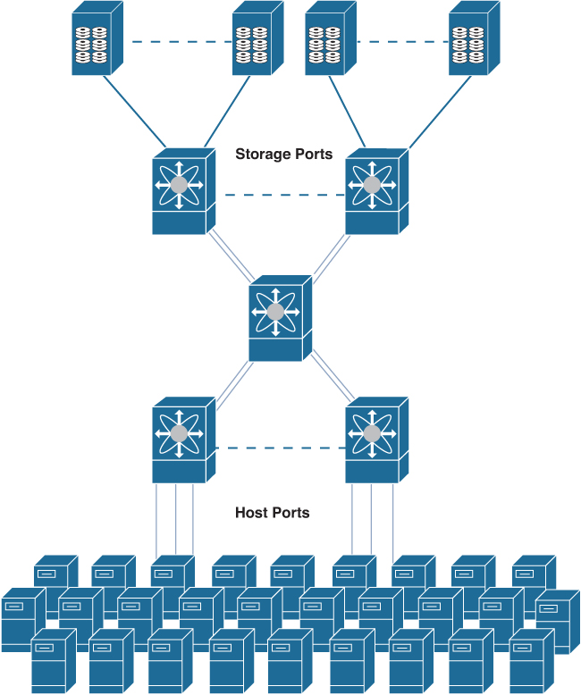
Figure 7-3 Edge-Core-Edge Topology
The resiliency of this topology is sufficiently high due to the redundant structure but without the excessive ISLs, as in the mesh topology. The performance of this topology is predictable, because paths between two communicating devices will not vary in length and hops; the direct path between two switches will always be chosen. Using ISL port channeling between the switches will provide for faster recovery time with no fabric-wide disruption. The port channels between the switches provide load sharing over a logical ISL link. This topology is simple to architect and implement and simple to maintain and troubleshoot.
![]()
Fibre Channel Port Types
The main function of a switch is to relay frames from one data link to another. These frames are sent and received using Fibre Channel interfaces/ports.
Each Fibre Channel interface can be used as a downlink (connected to a server) or as an uplink (connected to the data center SAN). Each physical Fibre Channel interface in a switch may operate in one of several port modes, such as E port, F port, TE port, SD port, and ST port. SD and ST ports will be discussed in Chapter 10, “Describe Software Management and Infrastructure Monitoring.” The use of NP, TF, and TNP modes will be more clear after we discuss the NPV and NPIV modes of fabric switches later in this chapter. Besides these modes, each interface may be configured in auto or Fx port modes. These two modes determine the port type during interface initialization. Interfaces are created in VSAN 1 by default. We discuss VSAN later in this chapter; for now let’s just compare VSANs in the storage world with VLANs in the Ethernet world.
Each interface has an associated administrative configuration and an operational status. The administrative configuration does not change unless you modify it. Administrative mode has various attributes that you can configure. The operational status represents the current status of a specified attribute, such as the interface speed. This status cannot be changed and is read-only. Some values, for example, operational speed, may not be valid when the interface is down.
Figure 7-4 shows various Fibre Channel port types.
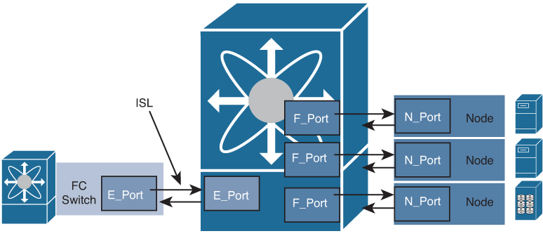
Figure 7-4 Fibre Channel Port Types
E Port
In expansion port (E port) mode, an interface functions as a fabric expansion port. This port can be connected to another E port to create an inter-switch link between two switches. E ports carry frames between switches for configuration and fabric management. They serve as a conduit between switches for frames destined for remote N ports. An E port connected to another switch can also be configured to form a port channel.
In fabric port (F port) mode, an interface functions as a fabric port. This port can be connected to a peripheral device (host or disk) operating as an N port. An F port can be attached to only one N port.
NP Ports
An NP port is a port on a device that is in NPV mode and connected to the core switch via an F port. NP ports function like N ports, except that in addition to providing N port operations, they also function as proxies for multiple physical N ports.
TE Port
In trunking E port (TE port) mode, an interface functions as a trunking expansion port. It can be connected to another TE port to create an extended ISL (EISL) between two switches. TE ports expand the functionality of E ports to support the following:
• VSAN trunking
• Transport quality of service (QoS) parameters
• Fibre Channel traceroute (fctrace) feature
In TE port mode, all the frames are transmitted in EISL frame format, which contains VSAN information. Interconnected switches use the VSAN ID to multiplex traffic from one or more VSANs across the same physical link.
TF Port
In trunking F port (TF port) mode, an interface functions as a trunking expansion port. It can be connected to another trunked N port (TN port) or trunked NP port (TNP port) to create a link between a core switch and an NPV switch or a host bus adapter (HBA) in order to carry tagged frames. TF ports expand the functionality of F ports to support VSAN trunking.
In TF port mode, all the frames are transmitted in EISL frame format, which contains VSAN information. Interconnected switches use the VSAN ID to multiplex traffic from one or more VSANs across the same physical link.
TNP Port
In trunking NP port (TNP port) mode, an interface functions as a trunking expansion port. It can be connected to a trunked F port (TF port) to create a link to a core NPIV switch from an NPV switch in order to carry tagged frames.
Fx Port
Interfaces configured as Fx ports can operate in either F port mode or FL port mode. FL port mode is used in arbitrated loop topology, which we do not discuss in this book. The Fx port mode is determined during interface initialization depending on the attached N port. Fx port mode configuration disallows interfaces to operate in any other mode—for example, preventing an interface to connect to another switch.
Auto Mode
Interfaces configured in auto mode can operate in F port, E port, TE port, or TF port mode. The port mode is determined during interface initialization. For example, if the interface is connected to a node (host or disk), it operates in F port mode depending on the N port mode. If the interface is attached to a third-party switch, it operates in E port mode. If the interface is attached to another FC switch—for example, Cisco MDS 9000 Series multilayer switches, it may become operational in TE port mode.
Note
Not all port modes are available in all types of Fibre Channel switches. Also, we skipped some port modes such as TL, NL, and FL port types because they are rarely used in today’s FC SAN environment.
Port mode on Fibre Channel interfaces can be configured using the switchport mode <port-type> command, as shown in Example 7-1.
Example 7-1 Fibre Channel Interface Configuration
switch# configure terminal
switch(config)# interface fc1/1
switch(config-if)# switchport mode F
or
switch(config-if)# switchport mode auto
Fibre Channel Addressing
In Fibre Channel fabric, there are two types of addresses: World Wide Names (WWNs) and Fibre Channel Identifiers (FCID). Every Fibre Channel port and node has a hard-coded address called the World Wide Name, which is assigned by the manufacturer. Each WWN is an 8- or 16-byte number, the length and format of which is determined by the most significant four bits, which are referred to as a Network Address Authority (NAA). The remainder of the value is derived from an IEEE organizational unique identifier (OUI) or from a company ID (CID) and vendor-supplied information. Each format defines a different way to arrange and/or interpret these components. When NAA = 1 or 2 or 5, the length of the WWN is 8 bytes. For NAA = 6, the length of the WWN is 16 bytes. In this book, we deal with only 8-bytes WWNs.
There are two types of WWNs: port WWN (pWWN) and node WWN (nWWN), as depicted in Figure 7-5. The pWWN uniquely identifies a port in the FC fabric, whereas the nWWN uniquely identifies a node in the FC fabric. The node can be any switch, a disk drive, an HBA that contains more than one port, an array controller, and so on.

Figure 7-5 Example of WWN, WWNN, and WWPN
When a node connects to the fabric, it performs a fabric login during which it is assigned a 3-byte FC address, or FCID. This FCID is used for routing frames across the fabric using Fabric Shortest Path First (FSPF) protocol, which automatically calculates the best path between any two switches in a fabric. FSPF is based on link state protocol and dynamically computes routes throughout a fabric by establishing the shortest and quickest path between any two switches. FSPF selects an alternative path in the event of the failure of a given path. FSPF supports multiple paths and automatically computes an alternative path around a failed link.
FCID is composed of 24 bits (3 bytes), as shown in Figure 7-6. Each field has specific meaning in FCID.
• Domain ID: The domain ID is assigned to each FC switch in a fabric and is unique to that switch. Because the upper FCIDs are reserved for various FC fabric services, such as 0xFFFFFF for broadcast and 0xFFFFFC for name server, the domain ID field restricts the maximum number of FC switches that can be connected in a fabric or VSAN to 239. Routing decisions are made based on domain ID bits of FCID.
• Area ID: The area ID represents a set of devices connected to N ports on a switch. This field restricts the maximum number of ports on a single FC switch to 256.
• Port ID: The port ID identifies a specific FC object in the fabric. Cisco uses a combination of area ID and port ID to provide a unique 16-bit address for each device.

Figure 7-6 Fibre Channel Identifier (FCID) Format
Some of the reserved FCIDs are shown in Table 7-2.
![]()
Table 7-2 Reserved FCIDs

Note
If you are coming from the Ethernet and IP world, you might compare WWNs with a MAC address and FCID with an IP address. But we recommend that you do not to do that to avoid confusion in the future.
Flow Control
Buffer-to-buffer credits (BB_credits) are a flow control mechanism to ensure that FC switches do not run out of buffers because switches must not drop frames. BB_credits are negotiated on a per-hop basis between ports when the link is brought up. When the transmitter sends a port login request, the receiver responds with an accept (ACC) frame that includes information on the size and number of frame buffers (BB_credits) the receiver has. The transmitter stores the BB_credits value and another value called buffer-to-buffer credits count (BB_credit_CNT) in a table. The BB_credits_CNT decreases with each packet placed on the wire from the transmitter side independent of the packet size. When a “receiver ready” acknowledgment signal is received from the receiver side, the BB_credits_CNT value is increased by one. The transmitting port keeps track of the BB_credits_CNT value to avoid overrunning the buffers on the receiving end. If the count becomes zero, no more packets are transmitted.
The BB_credit value can decrease the overall throughput of the link if insufficient BB_credits are available. The receive BB_credit value can be configured manually also for each FC interface. In most cases, you do not need to modify the default configuration. The receive BB_credit values depend on the switch/module type and the port mode. The range for assigning BB_credits is between 1 and 500 in all port modes. This value can be changed as required.
In Figure 7-7, the initiator has three transmit credits, and the receiver has three receive credits. When the initiator sends two frames on the wire, the transmit credits is decreased by two. When the initiator receives a “receiver ready” frame from the receiver, it increases its transmit credit by one and so on.
![]()

Figure 7-7 Flow Control Using Buffer-to-Buffer Credits
End-to-end credits are the maximum number of data frames a source port can send to a destination port without receiving an acknowledgment frame (ACK). This credit is granted during N port login and is replenished with the return of the ACK response frame. Buffer-to-buffer credits are negotiated on a per-hop basis between ports when the link is brought up, whereas end-to-end credits are negotiated between the source and destination port across the fabric.
Switched Fabric Initialization
![]()
The fabric initialization process consists of four phases:
• Principal switch selection: This phase guarantees the selection of a unique principal switch (PS) across the fabric.
• Domain ID distribution: This phase guarantees each switch in the fabric obtains a unique domain ID.
• FCID allocation: This phase guarantees a unique FCID assignment to each device attached to the corresponding switch in the fabric.
• Fabric reconfiguration: This phase guarantees a resynchronization of all switches in the fabric to ensure they simultaneously restart a new principal switch selection phase.
Each switch in a fabric is assigned one or more unique domain IDs using a two-step process. First, one switch, called the principal switch, is selected from the switches of a fabric. Then the principal switch assigns domain IDs to the other switches of the fabric. FCID address assignment within a domain is performed by the switch to which that domain ID is granted. The domains are configured on a per-VSAN basis. If you do not configure a domain ID, the local switch uses a random ID.
Note
Changes to fcdomain parameters should not be performed on a daily basis. These changes should be made by an administrator or individual who is completely familiar with switch operations. Fibre Channel domain parameters can be configured using the fcdomain command.
Principal Switch Selection
Each fabric has only one principal switch. The principal switch is responsible for distribution of domain IDs within the fabric.
![]()
Principal switch selection in a fabric is based on the following values:
• Run-time priority: The lowest run-time priority is considered the highest priority. By default, the configured priority is 128. The valid range to set the priority is between 1 and 254. The value 255 is accepted from other switches but cannot be locally configured.
• Switch WWN: The lowest switch WWN is given higher priority.
During the principal switch selection phase, the switch with the highest priority becomes the principal switch. If two switches have the same configured priority, the switch with the lower World Wide Name (WWN) becomes the principal switch.
As shown in Figure 7-8, when switch 1 is connected to switch 2, the principal switch election starts. Because both of the switches have the same configured priority, which is 128, the local WWN on both the switches is checked. Because switch 1 has the lowest WWN, it becomes the principal switch. When WWN is the principal switch election criterion, the runtime priority of the principal switch is automatically changed to 2.

Figure 7-8 Principal Switch Selection
The principal switch selection process is very complex. Figure 7-9 shows the messages exchanged during the principal switch selection process and domain ID distribution. For simplicity, let’s consider only two switches in the fabric.
![]()

Figure 7-9 Switched Fabric Initialization
When the two switches are connected via a link, they enter into the link initialization phase where they negotiate the port speed at which the ports are capable of operating. When the link is initialized, the switches enter into the exchange link parameters (ELP) phase. Information about the interfaces such as buffer-to-buffer credits, timers, and class of service are exchanged between the two switches using controller addresses (0xFFFFFD). The switches enter the exchange switch capabilities (ESC) phase when the neighboring fabric controller agrees on the routing protocol and recognizes the vendor ID of the switch. If the switches are Cisco MDS 9000 Series devices, they use Cisco-specific feature negotiations such as virtual SAN trunks in the Cisco proprietary Exchange Peer Parameters (EPP) frame. In the Exchange Fabric Parameters (EFP) phase, the principal switch is selected.
Domain ID Distribution
Domain IDs uniquely identify a switch in a VSAN. A switch may have different domain IDs in different VSANs. The domain ID is part of the overall FCID.
The configured domain ID can be preferred or static. When you assign a static domain ID type, you are requesting a particular domain ID. If the switch does not get the requested address, it will isolate itself from the fabric. When you specify a preferred domain ID, you are also requesting a particular domain ID; however, if the requested domain ID is unavailable, the switch will accept another domain ID. By default, the configured domain ID is 0 (zero) and the configured type is preferred. The 0 (zero) value can be configured only if the preferred option is used. If a domain ID is not configured, the local switch sends a random ID in its request. Static domain IDs are recommended.
When a subordinate switch requests a domain, the following process takes place:
• The local switch sends a configured domain ID request to the principal switch.
• The principal switch assigns the requested domain ID if available. Otherwise, it assigns another available domain ID.
The behavior for a subordinate switch changes based on three factors: the allowed domain ID lists, the configured domain ID, and the domain ID that the principal switch has assigned to the requesting switch. The valid range for an assigned domain ID list is from 1 to 239. You can specify a list of ranges to be in the allowed domain ID list and separate each range with a comma. The principal switch assigns domain IDs that are available in the locally configured allowed domain list.
When the received domain ID is not within the allowed list, the requested domain ID becomes the runtime domain ID, and all interfaces on that VSAN are isolated. When the assigned and requested domain IDs are the same, the preferred and static options are not relevant, and the assigned domain ID becomes the runtime domain ID.
When the assigned and requested domain IDs are different, the following cases apply:
• If the configured type is static, the assigned domain ID is discarded, all local interfaces are isolated, and the local switch assigns itself the configured domain ID, which becomes the runtime domain ID.
• If the configured type is preferred, the local switch accepts the domain ID assigned by the principal switch, and the assigned domain ID becomes the runtime domain ID.
Note
A static domain is specifically configured by the user and may be different from the runtime domain. If the domain IDs are different, the runtime domain ID changes to take on the static domain ID after the next restart, either disruptive or nondisruptive. If you perform a disruptive restart, reconfigure fabric (RCF) frames are sent to other switches in the fabric, and data traffic is disrupted on all the switches in the VSAN (including remotely segmented ISLs). If you perform a nondisruptive restart, build fabric (BF) frames are sent to other switches in the fabric, and data traffic is disrupted only on the switch.
If you change the configured domain ID, the change is accepted only if the new domain ID is included in all the allowed domain ID lists currently configured in the VSAN. Alternatively, you can also configure a zero-preferred domain ID.
Refer to Figure 7-9 for domain ID distribution phases. In the domain ID assigned (DIA) phase, the principal switch assigns itself a domain ID (1a) and floods the DIA frames with this information in the fabric. Each switch in the fabric that received the DIA frames from the principal switch requests a domain ID using a request domain identifier (RDI). The RDI request can contain a preferred (or static) domain ID depending on the configuration of the switch. In the next phase, the principal switch grants the requested domain ID or another from its domain list to the subordinate switch (SS). Lastly, the downstream switch accepts the domain ID (2b) if it is the same as the static ID or it belongs to its domain list. Finally, the fabric is formed. If the downstream switch doesn’t accept the domain ID, it becomes an isolated switch.
In Figure 7-10, the principal switch, switch 1, has a runtime domain ID of 3. The subordinate switch, switch 2, is configured with a domain ID of 7 as preferred. Switch 2 requests configured domain ID 7 from the principal switch. Because the assignment of domain ID 7 is not restricted by the Unallowed domain IDs list, the principal switch assigns domain ID 7 to switch 2. If domain ID 7 were in the Unallowed domain ID list, the principal switch would assign another domain ID, in this example 51, to the subordinate switch.
![]()
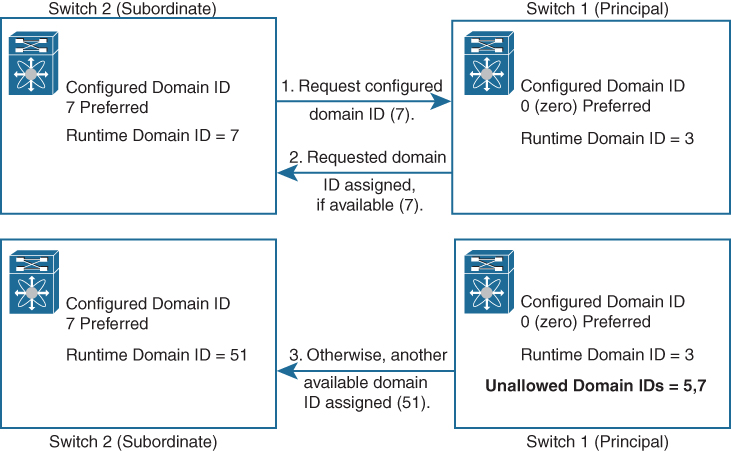
Figure 7-10 Configuration Process Using the Preferred Option
FCID Allocation
In this phase, when an N port logs in to a SAN switch, it is assigned an FCID. By default, the persistent FCID feature is enabled. When persistent FCIDs are enabled, the current FCIDs in use in the fcdomain are saved across reboots. The fcdomain automatically populates the database with dynamic entries that the switch has learned about after a device (host or disk) is plugged into a port interface. A persistent FCID assigned to an F port can be moved across interfaces and can continue to maintain the same persistent FCID. If the persistent FCID feature is disabled, the FCIDs are stored in a volatile cache, and the contents of this volatile cache are not saved across reboots.
Fabric Reconfiguration
In this phase, a resynchronization of all switches in the fabric happens to ensure they simultaneously restart a new principal switch selection phase. A new principal switch selection can be triggered in three ways: a switch reboot, a build fabric (BF) frame, or a reconfigure fabric (RCF) frame. A BF frame can be initiated manually, due to a link failure or when a configured fabric joins another configured fabric with nonoverlapping domain IDs. A BF frame requests a nondisruptive reconfiguration of the entire fabric where the connectivity is not lost. An RCF frame can be initiated manually or automatically if a switch is isolated. Most of the fabric switches have this automatic option disabled. An RCF frame requests a disruptive reconfiguration of the entire fabric, and the traffic is impacted in the fabric.
Device Registration: FLOGI, PLOGI, PRLI
After the switched fabric is initialized, the end devices connected to the fabric register to the switched fabric. When a device is connected to the FC fabric, the following three types of login are possible to the switched fabric:
![]()
• Fabric login (FLOGI): FLOGI happens between an N port and an F port. After an FC device (host) is attached to the FC fabric, it performs fabric login, as shown in Figure 7-11. The host (N port) sends the FLOGI request to the well-known fabric login server address 0xFFFFFE. The FLOGI frame contains its node name, N port name, and service parameters. When the fabric switch receives the FLOGI request, it responds with an accept (ACC) frame to the sender while setting appropriate bits on the ACC frame, indicating what service parameters are not supported. Once the fabric login is achieved, the switch assigns FCID to the node.
• Port login (PLOGI): PLOGI happens between two N ports. The N port sends a PLOGI request to the well-known directory service address 0xFFFFFC. The PLOGI frame contains the port address, port name, node name, B2B_credit capability, and other service parameters. When both N ports inform about their capabilities to one another using PLOGI requests, they are able to establish logical sessions between the two nodes, as shown in Figure 7-11.
• Process login (PRLI): PRLI happens between two processes originating from two different N ports. The processes that are involved can be system processes or a group of related processes.

Figure 7-11 FLOGI and PLOGI Processes
FLOGI and FCNS Databases
In the Ethernet world, an ARP table maintains a database for resolution between the MAC address (Layer 2) and IP address (Layer 3). Similarly, in the Fibre Channel world, every switch maintains an FLOGI and an FCNS database that maintains the resolution between WWNs (Layer 2) and FCIDs (Layer 3).
The FLOGI database logs every end device (server or storage) that has successfully performed a fabric login and obtained an FCID from the switch.
Fibre Channel switches share the FLOGI database information with each other using the Fibre Channel Name Service (FCNS). The name server functionality running on each switch maintains the FCNS database, which contains the attributes for all hosts and storage devices in each VSAN. Hence, each switch in the fabric learns where each WWN is and how to route traffic to specific WWNs. The name server permits an N port to register attributes during a PLOGI (to the name server) to obtain attributes of other hosts. These attributes are deregistered when the N port logs out either explicitly or implicitly.
![]()
In short, the FCNS database lists devices that are currently logged in to each VSAN, and the FLOGI database displays devices logged in to per switch. Example 7-2 shows sample output of the FLOGI and FCNS databases.
Example 7-2 Sample Output of show flogi database and show fcns database Commands
switch# show flogi database
----------------------------------------------------------------------------------
INTERFACE  VSAN    FCID        PORT NAME                   NODE NAME
----------------------------------------------------------------------------------
sup-fc0      2     0xb30100    10:00:00:05:30:00:49:63     20:00:00:05:30:00:49:5e
fc9/13       1     0xb200e2    21:00:00:04:cf:27:25:2c     20:00:00:04:cf:27:25:2c
fc9/13       1     0xb200e1    21:00:00:04:cf:4c:18:61     20:00:00:04:cf:4c:18:61
fc9/13       1     0xb200d1    21:00:00:04:cf:4c:18:64     20:00:00:04:cf:4c:18:64
fc9/13       1     0xb200ce    21:00:00:04:cf:4c:16:fb     20:00:00:04:cf:4c:16:fb
fc9/13       1     0xb200cd    21:00:00:04:cf:4c:18:f7     20:00:00:04:cf:4c:18:f7
Total number of flogi = 6.


switch# show fcns database
-------------------------------------------------------------------------------
FCID        TYPE  PWWN                      (VENDOR)        FC4-TYPE:FEATURE
-------------------------------------------------------------------------------
0x010000    N     50:06:0b:00:00:10:a7:80                   scsi-fcp fc-gs
0x010001    N     10:00:00:05:30:00:24:63   (Cisco)         ipfc
0x010002    N     50:06:04:82:c3:a0:98:52   (Company 1)     scsi-fcp 250
0x010100    N     21:00:00:e0:8b:02:99:36   (Company A)     scsi-fcp
0x020000    N     21:00:00:e0:8b:08:4b:20   (Company A)
0x020100    N     10:00:00:05:30:00:24:23   (Cisco)         ipfc
0x020200    N     21:01:00:e0:8b:22:99:36   (Company A)     scsi-fcp
CFS
Cisco Fabric Services (CFS) provides a common infrastructure for automatic configuration synchronization in the fabric. It provides the transport function as well as a rich set of common services to the applications. CFS has the ability to discover CFS-capable switches in the fabric and discover application capabilities in all CFS-capable switches.
The Cisco MDS NX-OS software uses the CFS infrastructure to enable efficient database distribution and to foster device flexibility. It simplifies SAN provisioning by automatically distributing configuration information to all switches in a fabric. Several Cisco MDS NX-OS applications use the CFS infrastructure to maintain and distribute the contents of a particular application’s database.
Many features in the Cisco MDS switches require configuration synchronization in all switches in the fabric. Maintaining configuration synchronization across a fabric is important to maintain fabric consistency. In the absence of a common infrastructure, such synchronization is achieved through manual configuration at each switch in the fabric. This process is tedious and error prone.
The following are some of the Cisco NX-OS features that use the CFS infrastructure:
• N port virtualization
• FlexAttach virtual pWWN
• NTP
• Dynamic port VSAN membership
• Distributed device alias services
• SAN device virtualization
• TACACS+ and RADIUS
• User and administrator roles
• Port security
• Call Home
• Syslog
• fctimer
• Saved startup configurations using the Fabric Startup Configuration Manager (FSCM)
• Allowed domain ID lists
• Registered state change notification (RSCN) timer
All CFS-based applications provide an option to enable or disable the distribution capabilities. The application configuration is not distributed by CFS unless distribution is explicitly enabled for that application.
The CFS functionality is independent of the lower-layer transport. CFS is a peer-to-peer protocol with no client/server relationship. CFS uses a proprietary SW_ILS (0x77434653) protocol for all CFS packets. CFS packets are sent to or from the switch domain controller addresses. CFS can also use IP to send information to other switches. Applications that use CFS are completely unaware of the lower layer transport.
CFS Features
![]()
CFS has the following features:
• Peer-to-peer protocol with no client/server relationship at the CFS layer.
• Three scopes of distribution:
• Logical scope: The distribution occurs within the scope of a VSAN.
• Physical scope: The distribution spans the entire physical topology.
• Over a selected set of VSANs: Some applications, such as Inter-VSAN Routing (IVR), require configuration distribution over some specific VSANs. These applications can specify to CFS the set of VSANs over which to restrict the distribution.
• Three modes of distribution:
• Coordinated distributions: Only one distribution is allowed in the fabric at any given time. CFS uses locks to enforce this. A coordinated distribution is not allowed to start if locks are taken for the application anywhere in the fabric. Coordinated distribution can be CFS driven or application driven. In a CFS-driven distribution, the lock is executed by CFS in response to an application request without intervention from the application. In an application-driven distribution, the fabric lock is under the complete control of the application.
• Uncoordinated distributions: Multiple parallel distributions are allowed in the fabric except when a coordinated distribution is in progress.
• Unrestricted uncoordinated distributions: Unrestricted uncoordinated distributions allow multiple parallel distributions in the fabric in the presence of an existing coordinated distribution. Unrestricted uncoordinated distributions are allowed to run in parallel with all other types of distributions.
• Support for a merge protocol that facilitates the merge of application configuration during a fabric merge event (when two independent fabrics merge).
CFS Fabric Lock
When you configure (first-time configuration) a Cisco NX-OS feature (or application) that uses the CFS infrastructure, that feature starts a CFS session and locks the fabric. When a fabric is locked, the Cisco NX-OS software does not allow any configuration changes from a switch to this Cisco NX-OS feature, other than the switch holding the lock, and issues a message to inform the user about the locked status. The configuration changes are held in a pending database by that application.
If you start a CFS session that requires a fabric lock but forget to end the session, an administrator can clear the session. If you lock a fabric at any time, your username is remembered across restarts and switchovers. If another user (on the same machine) tries to perform configuration tasks, that user’s attempts are rejected.
A commit operation saves the pending database for all application peers and releases the lock for all switches. In general, the commit function does not start a session; only a lock function starts a session. However, an empty commit is allowed if configuration changes were not previously made. In this case, a commit operation results in a session that acquires locks and distributes the current database.
When you commit configuration changes to a feature using the CFS infrastructure, you receive a notification about one of the following responses:
• One or more external switches report a successful status: The application applies the changes locally and releases the fabric lock.
• None of the external switches report a successful state: The application considers this state a failure and does not apply the changes to any switch in the fabric. The fabric lock is not released.
CFSoIP and CFSoFC
A mixed fabric of different platforms such as the Cisco Nexus 7000 Series, Cisco Nexus 5000 Series, and Cisco MDS 9000 Series can interact with each other using CFS over IP (CFSoIP) and/or CFS over FC (CFSoFC).
You can configure CFS to distribute information over IP for networks containing switches that are not reachable over Fibre Channel. CFS distribution over IP supports the following features:
• Physical distribution over an entirely IP network.
• Physical distribution over a hybrid Fibre Channel and IP network with the distribution reaching all switches that are reachable over either Fibre Channel or IP.
• Distribution over IP version 4 (IPv4) or IP version 6 (IPv6).
• Keepalive mechanism to detect network topology changes using a configurable multicast address.
• Compatibility with Cisco MDS NX-OS Release 4.x.
• Distribution for logical scope applications is not supported because the VSAN implementation is limited to Fibre Channel.
The switch attempts to distribute information over Fibre Channel first and then over the IP network if the first attempt over Fibre Channel fails. CFS does not send duplicate messages if distribution over both IP and Fibre Channel is enabled.
Figure 7-12 shows a network with both Fibre Channel and IP connections. Node A forwards an event to node B over Fibre Channel. Node B forwards the event to nodes C and D using unicast IP. Node C forwards the event to node E using Fibre Channel.
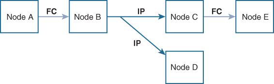
Figure 7-12 Network Example 1 with Fibre Channel and IP Connections
Figure 7-13 is the same as Figure 7-12 except that nodes D and E are connected using Fibre Channel. All processes are the same in this example because node B has node C and node D in the distribution list for IP. Node C does not forward to node D because node D is already in the distribution list from node B.
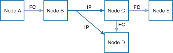
Figure 7-13 Network Example 2 with Fibre Channel and IP Connections
Figure 7-14 is the same as Figure 7-13 except that nodes D and E are connected using IP. Both nodes C and D forward the event to node E because node E is not in the distribution list from node B.
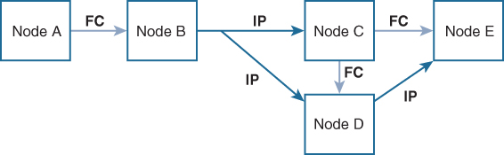
Figure 7-14 Network Example 3 with Fibre Channel and IP Connections
CFS over IP can also be used with static IP peers. In this case, dynamic discovery over IP multicast is disabled, and CFS distribution is done only on the peers configured statically. CFS uses the list of configured IP addresses to communicate with each peer and learn the peer switch WWN. After learning the peer switch WWN, CFS marks the switch as CFS-capable and triggers application-level merging and database distribution.
CFS Merge
An application keeps the configuration synchronized in a fabric through CFS. Two such fabrics might merge as a result of an ISL coming up between them. These two fabrics could have two different sets of configuration information that need to be reconciled in the event of a merge. CFS provides notification each time an application peer comes online. If a fabric with M application peers merges with another fabric with N application peers, and if an application triggers a merge action on every such notification, a link-up event results in M*N merges in the fabric.
CFS supports a protocol that reduces the number of merges required to one by handling the complexity of the merge at the CFS layer. This protocol runs per application per scope. The protocol involves selecting one switch in a fabric as the merge manager for that fabric. The other switches do not play any role in the merge process.
During a merge, the merge manager in the two fabrics exchange their configuration databases with each other. The application on one of them merges the information, decides if the merge is successful, and informs all switches in the combined fabric of the status of the merge.
In case of a successful merge, the merged database is distributed to all switches in the combined fabric, and the entire new fabric remains in a consistent state.
CFS Regions
A CFS region is a user-defined subset of switches for a given feature or application in its physical distribution scope. When a SAN is spanned across a vast geography, you may need to localize or restrict the distribution of certain profiles among a set of switches based on their physical proximity. CFS regions allow you to configure multiple islands of distribution within the fabric, for a given CFS feature or application. CFS regions are designed to restrict the distribution of a feature’s configuration to a specific set or grouping of switches in a fabric.
Note
You can only configure a CFS region on physical switches in a SAN. You cannot configure a CFS region in a VSAN.
CFS regions are identified by numbers ranging from 0 through 200. Region 0 is reserved as the default region, and it contains every switch in the fabric. You can configure regions from 1 through 200. If the feature is moved—that is, assigned to a new region—its scope is restricted to that region; it ignores all other regions for distribution or merging purposes. The assignment of the region to a feature has precedence in distribution over its initial physical scope. You can configure a CFS region to distribute configurations for multiple features. However, on a given switch, you can configure only one CFS region at a time to distribute the configuration for a given feature. Once you assign a feature to a CFS region, its configuration cannot be distributed within another CFS region.
Let’s discuss a scenario where CFS regions will be useful. Call Home is an application that triggers alerts to network administrators when a situation arises or something abnormal occurs. When the fabric covers many geographies and with multiple network administrators who are each responsible for a subset of switches in the fabric, the Call Home application sends alerts to all network administrators regardless of their location. For the Call Home application to send message alerts selectively to network administrators, the physical scope of the application has to be fine-tuned or narrowed down, which is achieved by implementing CFS regions.
Table 7-3 summarizes the NX-OS CLI commands that are related to CFS configuration and verification.
![]()
Table 7-3 Summary of NX-OS CLI Commands for CFS Configuration and Verification

VSAN
A VSAN is a virtual storage-area network (SAN). VSANs provide isolation among devices that are physically connected to the same fabric. With VSANs, you can create multiple logical SANs over a common physical infrastructure. Each VSAN is a logically and functionally separate SAN with its own set of Fibre Channel fabric services. This partitioning of fabric services greatly reduces network instability by containing fabric reconfigurations and error conditions within an individual VSAN. The strict traffic segregation provided by VSANs helps ensure that the control and data traffic of a specified VSAN are confined within the VSAN’s own domain, increasing SAN security. VSANs help reduce costs by facilitating consolidation of isolated SAN islands into a common infrastructure without compromising availability.
Users can create administrator roles that are limited in scope to certain VSANs. For example, a network administrator role can be set up to allow configuration of all platform-specific capabilities, while other roles can be set up to allow configuration and management only within specific VSANs. This approach improves the manageability of large SANs and reduces disruptions due to human error by isolating the effect of a user action to a specific VSAN whose membership can be assigned based on switch ports or the World Wide Name (WWN) of attached devices.
VSAN Features
With the introduction of VSANs, the network administrator can build a single topology containing switches, links, and one or more VSANs. Each VSAN in the topology has the same behavior and property as a SAN. A VSAN has the following additional features:
![]()
• Multiple VSANs can share the same physical topology.
• The same Fibre Channel identifiers (FCIDs) can be assigned to a host in another VSAN, thus increasing VSAN scalability.
• Every instance of a VSAN runs all required protocols such as FSPF, domain manager, and zoning (more on zoning later in this chapter).
• Fabric-related configurations in one VSAN do not affect the associated traffic in another VSAN.
• Events causing traffic disruptions in one VSAN are contained within that VSAN and are not propagated to other VSANs.
Figure 7-15 shows a physical Fibre Channel switching infrastructure with two defined VSANs: VSAN 2 (dashed) and VSAN 7 (solid). VSAN 2 includes hosts H1 and H2, application servers AS2 and AS3, and storage arrays SA1 and SA4. VSAN 7 connects H3, AS1, SA2, and SA3.
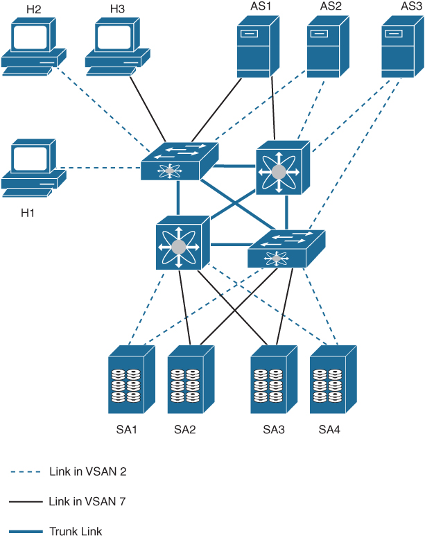
Figure 7-15 Example of Two VSANs
The four switches in this network are interconnected by trunk links that carry both VSAN 2 and VSAN 7 traffic. The inter-switch topology of both VSAN 2 and VSAN 7 are identical. This is not a requirement, and a network administrator can enable certain VSANs on certain links to create different VSAN topologies.
Without VSANs, a network administrator would need separate switches and links for separate SANs. When VSANs are enabled, the same switches and links may be shared by multiple VSANs. VSANs allow SANs to be built on port granularity instead of switch granularity. Figure 7-15 illustrates that a VSAN is a group of hosts or storage devices that communicate with each other using a virtual topology defined on the physical SAN.
The primary use of VSANs is to separate traffic based on certain criteria such as customer traffic segregation or to meet the needs of a particular department or application.
VSAN Attributes
VSANs have the following attributes:
![]()
• VSAN ID: The VSAN ID identifies the VSAN as the default VSAN (VSAN 1), user-defined VSANs (VSAN 2 to 4093), and the isolated VSAN (VSAN 4094).
• State: The administrative state of a VSAN can be configured to an active (default) or suspended state. When VSANs are created, they may exist in various conditions or states.
• The active state of a VSAN indicates that the VSAN is configured and enabled. By enabling a VSAN, you activate the services for that VSAN. A VSAN is in the operational state if the VSAN is active and at least one port is up. This state indicates that traffic can pass through this VSAN.
• The suspended state of a VSAN indicates that the VSAN is configured but not enabled. If a port is configured in this VSAN, it is disabled. Use this state to deactivate a VSAN without losing the VSAN’s configuration. All ports in a suspended VSAN are disabled. By suspending a VSAN, you can preconfigure all the VSAN parameters for the whole fabric and activate the VSAN immediately.
• VSAN name: This text string identifies the VSAN for management purposes. The name can be from 1 to 32 characters long, and it must be unique across all VSANs. By default, the VSAN name is a concatenation of VSAN and a four-digit string representing the VSAN ID. For example, the default name for VSAN 3 is VSAN0003. A VSAN name must be unique.
• Load-balancing attributes: These attributes indicate the use of the source-destination ID (src-dst-id) or the originator exchange OX ID (src-dst-ox-id, the default) for load-balancing path selection.
Note
Up to 256 VSANs can be configured in a switch. Of these, one is a default VSAN (VSAN 1), and another is an isolated VSAN (VSAN 4094). User-specified VSAN IDs range from 2 to 4093. VSAN 1 cannot be deleted, but it can be suspended. When you configure a port in VSAN 4094 or move a port to VSAN 4094, that port is immediately isolated. Each VSAN can contain up to 239 switches and has an independent address space that allows identical Fibre Channel IDs (FCIDs) to be used simultaneously in different VSANs.
VSAN Advantages
VSANs offer the following advantages:
• Traffic isolation: Traffic is contained within VSAN boundaries, and devices reside only in one VSAN, thus ensuring absolute separation between user groups, if desired.
• Scalability: VSANs are overlaid on top of a single physical fabric. The ability to create several logical VSAN layers increases the scalability of the SAN.
• Per-VSAN fabric services: Replication of fabric services on a per-VSAN basis provides increased scalability and availability.
• Redundancy: Several VSANs created on the same physical SAN ensure redundancy. If one VSAN fails, redundant protection (to another VSAN in the same physical SAN) is configured using a backup path between the host and the device.
• Ease of configuration: Users can be added, moved, or changed between VSANs without changing the physical structure of a SAN. Moving a device from one VSAN to another only requires configuration at the port level, not at a physical level.
Port VSAN Membership (DPVM)
Port VSAN membership on the switch is assigned on a port-by-port basis. By default, each port belongs to the default VSAN. You can assign VSANs to ports either statically or dynamically. To assign dynamic VSAN membership to ports, you assign VSANs based on the device WWN. This method is referred to as Dynamic Port VSAN Membership (DPVM). DPVM offers flexibility and eliminates the need to reconfigure the port VSAN membership to maintain fabric topology when a host or storage device connection is moved between two Cisco fabric switches or two ports within a switch. DPVM retains the configured VSAN regardless of where a device is connected or moved.
DPVM configurations are based on port World Wide Name (pWWN) and node World Wide Name (nWWN) assignments. DPVM contains mapping information for each device pWWN/nWWN assignment and the corresponding VSAN. The Cisco NX-OS software checks DPVM active configuration during a device FLOGI and obtains the required VSAN details.
The pWWN identifies the host or device, and the nWWN identifies a node consisting of multiple devices. You can assign any one of these identifiers or any combination of these identifiers to configure DPVM mapping. If you assign a combination, preference is given to the pWWN.
DPVM can be configured to automatically learn (autolearn) new devices within each VSAN. DPVM autolearn can be enabled or disabled at any time. Learned entries are created by populating device pWWNs and VSANs. DPVM should be activated before autolearn can be enabled. Autolearned entries can also be manually deleted. The autolearned entries become permanent when DPVM autolearn is disabled.
DPVM uses the Cisco Fabric Services infrastructure to allow efficient database management and distribution. DPVM uses the application-driven, coordinated distribution mode and the fabric-wide distribution scope.
VSAN Trunking
VSAN trunking enables interconnected ports to transmit and receive frames in more than one VSAN. Trunking is supported on E ports and F ports. VSAN trunking is supported on native Fibre Channel interfaces and virtual Fibre Channel interfaces.
The trunking protocol is important for E port and TE port operations. It supports the following capabilities:
• Dynamic negotiation of operational trunk mode
• Selection of a common set of trunk-allowed VSANs
• Detection of a VSAN mismatch across an ISL
Trunking configurations are applicable only to E ports. If trunk mode is enabled in an E port and that port becomes operational as a trunking E port, it is referred to as a TE port, as shown in Figure 7-16. The trunk-allowed VSANs configured for TE ports are used by the trunking protocol to determine the allowed-active VSANs in which frames can be received or transmitted. If a trunking-enabled E port is connected to a third-party switch, the trunking protocol ensures seamless operation as an E port.
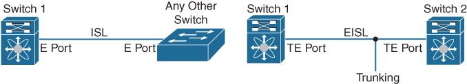
Figure 7-16 VSAN Trunking Between Cisco-Cisco and Cisco-Third Party Switches
If you misconfigure VSAN configurations across E ports, issues can occur, such as the merging of traffic in two VSANs (causing both VSANs to mismatch), as shown in Figure 7-17. The VSAN trunking protocol validates the VSAN interfaces at both ends of an ISL to avoid merging VSANs. The trunking protocol cannot detect merging of VSANs when a third-party switch is placed in between two Cisco SAN switches, as shown in Figure 7-18.
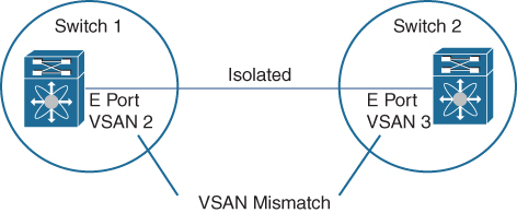
Figure 7-17 VSAN Mismatch Between Cisco Switches

Figure 7-18 VSAN Mismatch Between Cisco Switches with Third-Party Switch in Between
VSAN 2 and VSAN 3 are effectively merged with overlapping entries in the name server and the zone applications. Cisco MDS 9000 Fabric Manager helps detect such topologies.
By default, the VSAN trunking protocol is enabled. If the trunking protocol is disabled on a switch, no port on that switch can apply new trunk configurations. Existing trunk configurations are not affected: the TE port continues to function in trunk mode but only supports traffic in VSANs that it negotiated with previously (when the trunking protocol was enabled). Other switches that are directly connected to this switch are similarly affected on the connected interfaces. If you need to merge traffic from different port VSANs across a nontrunking ISL, disable the trunking protocol.
By default, trunk mode is enabled in all Fibre Channel interfaces. However, trunk mode configuration takes effect only in E port mode. You can configure trunk mode as on (enabled), off (disabled), or auto (automatic). The default trunk mode is on. The trunk mode configurations at the two ends of the link determine the trunking state of the link and the port modes at both ends, as shown in Table 7-4.
![]()
Table 7-4 Trunk Mode Status Between Switches

Note
When connected to a third-party switch, the trunk mode configuration has no effect. The inter-switch link (ISL) is always in a trunking disabled state.
Each Fibre Channel interface has an associated trunk-allowed VSAN list. In TE port mode, frames are transmitted and received in one or more VSANs specified in this list. By default, the complete VSAN range (1 through 4093) is included in the trunk-allowed list. The common set of VSANs that are configured and active in the switch are included in the trunk-allowed VSAN list for an interface, and they are called allowed-active VSANs. The trunking protocol uses the list of allowed-active VSANs at the two ends of an ISL to determine the list of operational VSANs in which traffic is allowed. You can configure a selected set of VSANs (from the allowed-active list) to control access to the VSANs specified in a trunking ISL. The allowed VSANs are configured on a per-interface basis.
In Figure 7-19, switch 1 has VSANs 1 through 5; switch 2 has VSANs 1 through 3; and switch 3 has VSANs 1, 2, 4, and 5. However, only the common set of allowed-active VSANs at the ends of the ISL become operational. The ISL between switch 1 and switch 2 includes VSAN 1 and VSAN 3. The ISL between switch 2 and switch 3 includes VSAN 1 and VSAN 2. The ISL between switch 3 and switch 1 includes VSAN 1, 2, and 5. VSAN 2 can only be routed from switch 1 through switch 3 to switch 2.
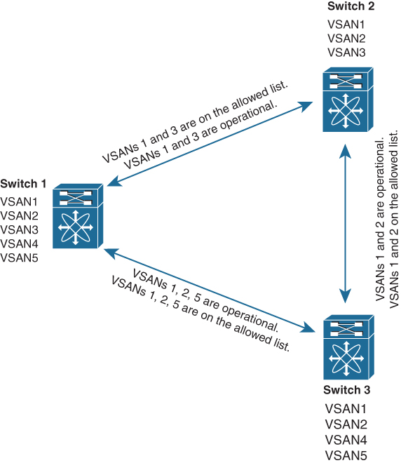
Figure 7-19 Operational and Allowed VSAN Configuration
Table 7-5 summarizes the NX-OS CLI commands that are related to VSAN configuration and verification.
![]()
Table 7-5 Summary of NX-OS CLI Commands for VSAN Configuration and Verification


Example 7-3 shows how to configure and verify VSANs on the sample topology shown in Figure 7-20. The example shows the configuration only for MDS-9148S-1; the configuration for MDS9148S-2 is similar.
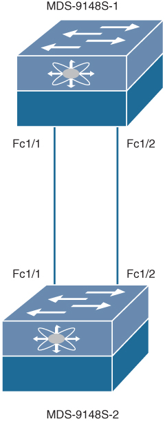
Figure 7-20 Sample Topology for VSAN Creation and Verification
Example 7-3 VSAN Creation and Verification on MDS-9148S Switch
! Initial configuration and entering the VSAN database
MDS-9148S-1# conf t
Enter configuration commands, one per line.  End with CNTL/Z.
MDS-9148S-1(config)# vsan database

! Creating VSAN 11 with name VSAN11 and configuring interfaces for VSAN 11.
MDS-9148S-1(config-vsan-db)# vsan 11 name VSAN11
MDS-9148S-1(config-vsan-db)# vsan 11 interface fc1/1, fc1/2

! Configuring interfaces as E ports
MDS-9148S-1(config-vsan-db)# int fc 1/1, fc 1/2
MDS-9148S-1(config-if)# switchport mode E
MDS-9148S-1(config-if)# no shut

! Verifying status of the interfaces
MDS-9148S-1(config-if)# show interface fc 1/1, fc1/2 brief

-----------------------------------------------------------------------------------------
Interface  Vsan   Admin  Admin    Status       SFP  Oper  Oper       Port     Logical
                  Mode   Trunk                      Mode  Speed     Channel   Type
                         Mode                             (Gbps)
-----------------------------------------------------------------------------------------
fc1/1       11      E      on     trunking     swl   TE     8         --       core
fc1/2       11      E      on     trunking     swl   TE     8         --       core

! Verifying the VSAN membership
MDS-9148S-1(config)# show vsan membership
vsan 1 interfaces:
    fc1/4             fc1/5             fc1/6             fc1/7
    fc1/8             fc1/9             fc1/10            fc1/11
<....output omitted....>
    fc1/48

vsan 11 interfaces:
    fc1/1             fc1/2             fc1/3

vsan 4079(evfp_isolated_vsan) interfaces:

vsan 4094(isolated_vsan) interfaces:

! Verifying the VSAN usage
MDS-9148S-1(config)# show vsan usage
2 vsan configured
configured vsans:1,11
vsans available for configuration:2-10,12-4078,4080-4093

! Verifying all VSANs configured on the switch
MDS-9148S-1(config)# show vsan
vsan 1 information
         name:VSAN0001  state:active
         interoperability mode:default
         loadbalancing:src-id/dst-id/oxid
         operational state:down
vsan 11 information
         name:VSAN11  state:active
         interoperability mode:default
         loadbalancing:src-id/dst-id/oxid
         operational state:up

vsan 4079:evfp_isolated_vsan

vsan 4094:isolated_vsan

MDS-9148S-1(config)#
SAN Port Channels
SAN port channels refer to the aggregation of multiple physical interfaces into one logical interface to provide higher aggregated bandwidth, load balancing, and link redundancy. Port channels can connect to interfaces across switching modules, so a failure of a switching module cannot bring down the port channel link.
In Figure 7-21, port channel A aggregates two links on two interfaces on the same switching module at each end of a connection. Port channel B also aggregates two links, but each link is connected to a different switching module. If the switching module goes down, traffic is not affected.

Figure 7-21 Port Channel Flexibility
Types of SAN Port Channels
An E port channel provides a point-to-point connection over ISL (E ports) or EISL (TE ports), as shown in Figure 7-22. Multiple links can be combined into a port channel, and it increases the aggregate bandwidth on an ISL by distributing traffic among all functional links in the channel. It load balances across multiple links and maintains optimum bandwidth utilization. Load balancing is based on the source ID, destination ID, and exchange ID (OX ID). The E port channel provides high availability on an ISL. If one link fails, traffic previously carried on this link is switched to the remaining links. If a link goes down in a port channel, the upper protocol is not aware of it. To the upper protocol, the link is still there, although the bandwidth is diminished. The routing tables are not affected by link failure. Port channels may contain up to 16 physical links and may span multiple modules for added high availability. Trunking enables a link transmitting frames in the EISL format to carry (trunk) multiple VSAN traffic.
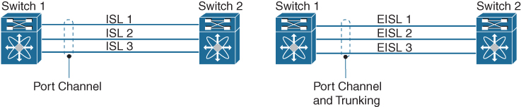
Figure 7-22 Port Channel and Trunking
An F port channel is also a logical interface that combines a set of F ports connected to the same Fibre Channel node and operates as one link between the F ports and the NP ports. F port channels are mainly used to connect NX-OS Core and NPV switches to provide optimal bandwidth utilization and transparent failover between the uplinks of a VSAN. An F port channel trunk combines the functionality and advantages of a TF port and an F port channel.
![]()
Port channels also can form between the following set of ports:
• E ports and TE ports
• F ports and NP ports
• TF ports and TNP ports
A port can be configured as a member of a static port channel only if the following configurations are the same in the port and the port channel:
• Speed
• Mode
• Rate mode
• Port VSAN
• Trunking mode
• Allowed VSAN list or VF-ID list
A compatibility check ensures that the same parameter settings are used in all physical ports in the channel. Otherwise, they cannot become part of a port channel. The compatibility check is performed before a port is added to the port channel.
The check ensures that the following parameters and settings match at both ends of a port channel:
• Capability parameters (type of interface, Gigabit Ethernet at both ends, or Fibre Channel at both ends).
• Administrative compatibility parameters (speed, mode, rate mode, port VSAN, allowed VSAN list, and port security). A port addition procedure fails if the capability and administrative parameters in the remote switch are incompatible with the capability and administrative parameters in the local switch.
• Operational parameters (remote switch WWN and trunking mode). If the operational parameters are incompatible, the compatibility check fails, and the interface is placed in a suspended (if On mode is configured) or isolated state (if Active mode is configured) based on the configured mode. We discuss port channel modes later in this chapter.
Note
Ports in Shared rate mode cannot form a port channel or a trunking port channel.
A port channel group can be automatically created when compatible links come up between two compatible switches if channel group autocreation is enabled in all ports at both ends using the channel-group auto command under the interface.
Port Channel Load Balancing
![]()
Load-balancing functionality on SAN port channels can be provided using the following methods:
• Flow based: All frames between source and destination follow the same links for a given flow. That is, whichever link is selected for the first exchange of the flow is used for all subsequent exchanges.
• Exchange based: The first frame in an exchange is assigned to a link, and then subsequent frames in the exchange follow the same link. However, subsequent exchanges can use a different link. This method provides finer granularity for load balancing while preserving the order of frames for each exchange.
Figure 7-23 illustrates how flow-based load balancing works. When the first frame in a flow is received on an interface for forwarding, link 1 is selected. Each subsequent frame in that flow is sent over the same link. No frame in Source ID 1 (SID1) and Destination ID 1 (DID1) utilizes link 2. All the frames in SID2 and DID2 use link 2.

Figure 7-23 Flow-Based Load Balancing
Figure 7-24 illustrates how exchange-based load balancing works. When the first frame in an exchange is received for forwarding on an interface, link 1 is chosen by a hash algorithm. All remaining frames in that particular exchange are sent on the same link. For exchange 1, no frame uses link 2. For the next exchange, link 2 is chosen by the hash algorithm. Now all frames in exchange 2 use link 2.

Figure 7-24 Exchange-Based Load Balancing
Port Channel Modes
You can configure each SAN port channel with a channel group mode parameter to determine the port channel protocol behavior for all member ports in this channel group. The possible values for a channel group mode are as follows:
• On mode (default): The member ports only operate as part of a SAN port channel or remain inactive. In this mode, the port channel protocol is not initiated. However, if a port channel protocol frame is received from a peer port, the software indicates its nonnegotiable status. Port channels configured in the On mode require you to explicitly enable and disable the port channel member ports at either end if you add or remove ports from the port channel configuration. You must physically verify that the local and remote ports are connected to each other.
• Active mode: The member ports initiate port channel protocol negotiation with the peer port(s) regardless of the channel group mode of the peer port. If the peer port, while configured in a channel group, does not support the port channel protocol or responds with a nonnegotiable status, it will default to the On mode behavior. The Active port channel mode allows automatic recovery without explicitly enabling and disabling the port channel member ports at either end.
Note
An F port channel is supported only in Active mode.
Table 7-6 compares On and Active modes of the port channel.
![]()
Table 7-6 Channel Group Configuration Differences

Table 7-7 summarizes the NX-OS CLI commands that are related to port channel configuration and verification.
![]()
Table 7-7 Summary of NX-OS CLI Commands for Port Channel Configuration and Verification

Let’s continue from the previous example of VSAN creation. This example uses the same topology as shown in Figure 7-25. Now you will create a port channel between the two links fc1/1 and fc1/2. Example 7-4 shows configuration only for MDS-9148S-1; the configuration for MDS9148S-2 is similar.
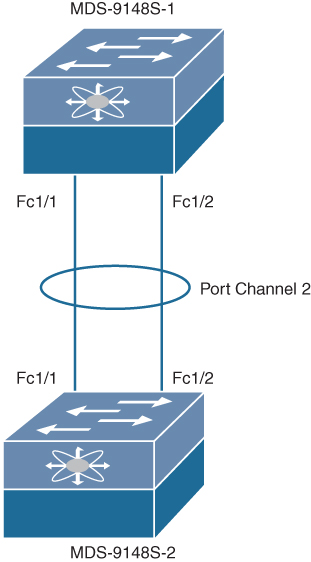
Figure 7-25 Sample Topology for Port Channel Creation and Verification
Example 7-4 SAN Port Channel Creation and Verification on MDS-9148S Switch
! Adding Physical Fibre Channel Ports to Port-Group 2 as E ports.
MDS-9148S-1(config)# int fc1/1, fc1/2
MDS-9148S-1(config)# switchport mode E
MDS-9148S-1(config-if)# channel-group 2
fc1/1 fc1/2 added to port-channel 2 and disabled
please do the same operation on the switch at the other end of the port-channel,
then do “no shutdown” at both ends to bring it up
MDS-9148S-1(config-if)# no shutdown

! Configuring Port Channel 2 as Trunk with allowed VSAN 11
MDS-9148S-1(config-if)# int port-channel 2
MDS-9148S-1(config-if)# switchport trunk allowed vsan 11
Warning: This command will remove all VSANs currently being trunked and trunk only the specified VSANs.
Do you want to continue? (y/n) [n] y
MDS-9148S-1(config-if)# no shutdown

! Verifying Port Channel 2 summary and interface details
MDS-9148S_1(config-if)# show port-channel summary
--------------------------------------------------------------------------
Interface           Total Ports        Oper Ports        First Oper Port
--------------------------------------------------------------------------

port-channel 2           2                 2                  fc1/1

MDS-9148S-1(config-if)# show interface port-channel 2
port-channel2 is trunking
    Hardware is Fibre Channel
    Port WWN is 24:02:8c:60:4f:cf:7f:70
    Admin port mode is E, trunk mode is on
    snmp link state traps are enabled
    Port mode is TE
    Port vsan is 11
    Speed is 16 Gbps
    Logical type is core
    Trunk vsans (admin allowed and active) (11)
    Trunk vsans (up)                       (11)
    Trunk vsans (isolated)                 ()
    Trunk vsans (initializing)             ()
    5 minutes input rate 640 bits/sec,80 bytes/sec, 0 frames/sec
    5 minutes output rate 640 bits/sec,80 bytes/sec, 0 frames/sec
      1888 frames input,160664 bytes
        0 discards,0 errors
        0 invalid CRC/FCS,0 unknown class
        0 too long,0 too short
      1807 frames output,143428 bytes
        1 discards,0 errors
      26 input OLS,7  LRR,0 NOS,0 loop inits
      28 output OLS,47 LRR, 28 NOS, 4 loop inits
    Member[1] : fc1/1     [up] *
    Member[2] : fc1/2     [up]
    Interface last changed at Wed Jul 24 00:41:27 2019

! Verifying Port Channel Database. The asterisks (*) indicate which interface came online first.
MDS-9148S-1# show port-channel database
port-channel2
    Administrative channel mode is on
    Operational channel mode is on
    Last membership update succeeded
    First operational port is fc1/1
    2 ports in total, 2 ports up
    Ports:   fc1/1    [up] *
             fc1/2    [up]
Zoning
Zoning enables you to set up access control between storage devices or user groups. If you have administrator privileges in your fabric, you can create zones to increase network security and to prevent data loss or corruption. Zoning is enforced by examining the source-destination ID field.
Zoning Features
![]()
Zoning has the following features:
• A zone consists of multiple zone members.
• Members in a zone can access each other; members in different zones cannot access each other.
• If zoning is not activated, all devices are members of the default zone.
• If zoning is activated, any device that is not in an active zone (a zone that is part of an active zone set) is a member of the default zone.
• Zones can vary in size.
• Devices can belong to more than one zone.
• A zone set consists of one or more zones.
• A zone set can be activated or deactivated as a single entity across all switches in the fabric.
• Only one zone set can be activated at any time.
• A zone can be a member of more than one zone set.
• A zone switch can have a maximum of 1000 zone sets (Cisco MDS Series switches) or 500 zone sets (Cisco Nexus 5000 Series switches).
• Zoning can be administered from any switch in the fabric.
• When you activate a zone (from any switch), all switches in the fabric receive the active zone set. Additionally, full zone sets are distributed to all switches in the fabric if this feature is enabled in the source switch.
• If a new switch is added to an existing fabric, zone sets are acquired by the new switch.
• Zone changes can be configured nondisruptively. New zones and zone sets can be activated without interrupting traffic on unaffected ports or devices.
• Zone membership criteria are based mainly on WWNs or FCIDs. You can configure and use FC alias, also called the zone alias, while configuring zone membership of initiators and targets for specific zones. The following criteria can be used while defining zone members:
• Port World Wide Name (pWWN): Specifies the pWWN of an N port attached to the switch as a member of the zone.
• Fabric pWWN: Specifies the WWN of the fabric port (the switch port’s WWN). This membership is also referred to as port-based zoning.
• FCID: Specifies the FCID of an N port attached to the switch as a member of the zone.
• Interface and switch WWN (sWWN): Specifies the interface of a switch identified by the sWWN. This membership is also referred to as interface-based zoning.
• Interface and domain ID: Specifies the interface of a switch identified by the domain ID.
• Domain ID and port number: Specifies the domain ID of an MDS domain and additionally specifies a port belonging to a non-Cisco switch.
• IPv4 address: Specifies the IPv4 address (and optionally the subnet mask) of an attached device.
• IPv6 address: The IPv6 address of an attached device in 128 bits in colon-separated hexadecimal format.
• Symbolic-nodename: Specifies the member symbolic node name. The maximum length is 240 characters.
• Default zone membership includes all ports or WWNs that do not have a specific membership association. Access between default zone members is controlled by the default zone policy.
All members of a zone can communicate with each other. For a zone with N members, N *(N – 1) access permissions need to be enabled. The best practice is to avoid configuring large numbers of targets or large numbers of initiators in a single zone. This type of configuration wastes switch resources by provisioning and managing many communicating pairs (initiator-to-initiator or target-to-target) that will never actually communicate with each other. For this reason, a single initiator with a single target is the most efficient approach to zoning.
The following specifics must be considered when creating zone members:
• Configuring only one initiator and one target for a zone provides the most efficient use of the switch resources.
• Configuring the same initiator to multiple targets is accepted.
• Configuring multiple initiators to multiple targets is not recommended.
• While configuring a zone member based on interface type, you should always select a fabric switch that potentially has the highest interface count in the fabric.
Figure 7-26 shows a zone set with two zones—zone 1 and zone 2—in a fabric. Zone 1 provides access from all three hosts (H1, H2, H3) to the data residing on storage systems S1 and S2. Zone 2 restricts the data on S3 to access only by H3. H3 resides in both zones.
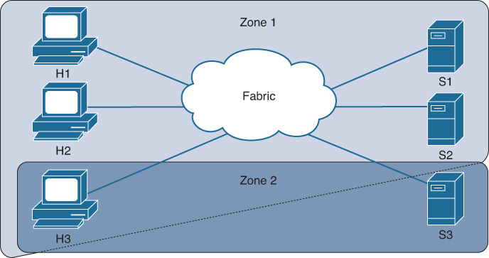
Figure 7-26 Fabric with Two Zones
Sometimes zones can be confused with VSANs. Two VSANs are equivalent to two unconnected SANs; zone A on VSAN 1 is different and separate from zone A in VSAN 2. You can also define multiple zones in a VSAN. Table 7-8 lists the differences between VSANs and zones.
Table 7-8 VSAN and Zone Comparison

Zone Enforcement
Zoning can be enforced in two ways: soft and hard. Each end device (N port) discovers other devices in the fabric by querying the name server. When a device logs in to the name server, the name server returns the list of other devices that can be accessed by the querying device. If an N port does not know about the FCIDs of other devices outside its zone, it cannot access those devices.
![]()
In soft zoning, zoning restrictions are applied only during interaction between the name server and the end device. If an end device somehow knows the FCID of a device outside its zone, it can access that device.
In this mode, only control plane traffic is policed by the switch supervisor/CPU services. In particular, the Fibre Channel Name Server (FCNS) will limit the list of permitted devices in an FCNS reply to only those that are in the zone configuration. However, the end device data plane traffic is unpoliced. This means a rogue end device may connect to other devices it is not zoned with.
Hard zoning is enforced by the hardware on each frame sent by an N port. As frames enter the switch, source-destination IDs are compared with permitted combinations to allow the frame at wirespeed. Hard zoning is applied to all forms of zoning. Hard zoning enforces zoning restrictions on every frame and prevents unauthorized access.
In this mode, both control plane and data plane traffic are policed. Control plane traffic is policed by the switch supervisor/CPU, and data plane traffic is policed on each ingress port with hardware assistance. The policing rules are set by the zone set that is programmed into each linecard/port ASIC. The destination of each frame is checked by hardware and, if it is not permitted by zoning, it is dropped. In this mode, any device can communicate only with end devices it is authorized to.
Cisco SAN switches support both hard and soft zoning. By default, both types of zoning are enabled, with hard zoning used in priority over soft zoning. In the event that the system is unable to use hard zoning due to hardware resource exhaustion, it will be disabled and the system will fall back to use soft zoning.
Full and Active Zone Set
Zones provide a method for specifying access control, while zone sets are a grouping of zones to enforce access control in the fabric. Zone sets are configured with the names of the member zones and the VSAN (if the zone set is in a configured VSAN). You can make a copy of a zone set and then edit it without altering the original zone set. You can copy an active zone set from the bootflash: directory, volatile: directory, or slot0, to one of the following areas:
• To the full zone set
• To a remote location (using FTP, SCP, SFTP, or TFTP)
The active zone set is not part of the full zone set. You cannot make changes to an existing zone set and activate it if the full zone set is lost or is not propagated.
Before configuring a zone set, consider these specifics:
• Each VSAN can have multiple zone sets, but only one zone set can be active at any given time.
• When you create a zone set, that zone set becomes a part of the full zone set.
• When you activate a zone set, a copy of the zone set from the full zone set is used to enforce zoning and is called the active zone set. An active zone set cannot be modified. A zone that is part of an active zone set is called an active zone.
• The administrator can modify the full zone set even if a zone set with the same name is active. However, the modification will be enforced only upon reactivation.
• When the activation is done, the active zone set is automatically stored in persistent configuration. This enables the switch to preserve the active zone set information across switch resets.
• All other switches in the fabric receive the active zone set so they can enforce zoning in their respective switches.
• Hard and soft zoning are implemented using the active zone set. Modifications take effect during zone set activation.
Note
If one zone set is active and you activate another zone set, the currently active zone set is automatically deactivated. You do not need to explicitly deactivate the currently active zone set before activating a new zone set.
Figure 7-27 shows a full zone set consisting of Z1 and Z2 zone sets. The Z1 zone set has zones A, B, and C as its zone members, and the Z2 zone set has zones C, D, and E as its zone members. Although two zone sets are configured on the switch, none of them are in an active state. When you activate zone set Z1, it becomes an active zone set in the fabric.
![]()
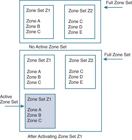
Figure 7-27 Full and Active Zone Sets
When zone D is added as a member of the currently active zone set Z1, as shown in Figure 7-28, it will not be part of the active zone set unless and until you activate zone set Z1 again.
![]()

Figure 7-28 Adding New Zone to Active Zone Sets
You can distribute full zone sets using one of two methods: one-time distribution using the zoneset distribute vsan command at the EXEC mode level or full zone set distribution using the zoneset distribute full vsan command at the configuration mode level. The zoneset distribute vsan command only distributes the full zone set information; it does not save the information to the startup configuration. You must explicitly save the running configuration to the startup configuration.
One-time distribution distributes the full zone set information immediately. But it does not distribute the full zone set information along with the active zone set during the activation, deactivation, or merge process.
Full zone set distribution does not distribute the full zone set immediately. But it distributes the full zone set information along with the active zone set during activation, deactivation, and the merge processes.
Autozone
The Autozone feature is a mechanism to automate zoning of devices. This feature can be used to reduce the administrative overhead of manually creating and updating the switch zone configuration each time a device is added to the SAN to a one-time command. An administrator has to configure the Autozone feature after the initial deployment and does not have to manually change or modify the zone configuration each time a new device is added to a fabric. The Autozone feature is intended for fabrics composed of a single fabric switch that has no more than 100 devices connected.
Initially, Autozone configures zoning that enables connectivity from every initiator to every target. The zones that are created are placed in a single zone set in VSAN 1 and activated. When in automatic mode, a Scheduler job is created to scan for newly logged-in devices every five minutes. New initiators are zoned with all the targets, and new targets are zoned with all the initiators. The new zones are then added to the active zone set. This process allows the switch to be administered with minimal effort by simply plugging in new devices and having automatic connectivity for the devices within minutes. The administrator can run Autozone manually if connectivity to the newly logged-in devices is required before the next scheduled scan. Autozone does not change the existing zones created either by Autozone or manually by an administrator. This prevents duplication of any existing zones by Autozone and allows an administrator to manually add specialized zones.
Autozone has two modes of operation:
• Automatic mode: The Autozone Scheduler job runs every five minutes, checking for changes in device logins, and updates the zone set accordingly.
• Manual mode: No Scheduler job is created. The administrator has to run the autozone --update command each time a new device is connected to a switch for the device to be added to the zoning configuration.
Note
Autozone works on single-switch fabrics. It works only for ports that are logged on VSAN 1. If the administrator moves ports to other VSANs, Autozone does not move them back into VSAN 1 or zone them.
Zone Merge
All Cisco SAN switches distribute active zone sets when new E port links come up or when a new zone set is activated in a VSAN. When two switches in a fabric are merged using a TE or E port, these TE and E ports may become isolated when the active zone set databases are different between the two switches or fabrics, as shown in Figure 7-29. When a TE port or an E port becomes isolated, you can recover that port from its isolated state using one of three options:
• Import the neighboring switch’s active zone set database and replace the current active zone set.
• Export the current database to the neighboring switch.
• Manually resolve the conflict by editing the full zone set, activating the corrected zone set, and then bringing up the link.
![]()

Figure 7-29 Importing and Exporting the Database
On Cisco SAN switches, you cannot edit an active zone set. However, you can copy an active zone set to create a new zone set that you can edit. Also, you can back up the zone configuration to a workstation using TFTP. This zone backup file can then be used to restore the zone configuration on a switch. Restoring the zone configuration overwrites any existing zone configuration on a switch.
Smart Zoning
Smart zoning implements hard zoning of large zones with fewer hardware resources than was previously required. The traditional zoning method allows each device in a zone to communicate with every other device in the zone, and the administrator is required to manage the individual zones. Smart zoning eliminates the need to create a single initiator to single target zones. By analyzing device-type information in the FCNS, the Cisco MDS NX-OS software can implement useful combinations at the hardware level, and the combinations that are not used are ignored. For example, initiator-target pairs are configured, but not initiator-initiator. The device is treated as unknown if during zone convert, the device is not logged in to the fabric, or when the zone is created, the initiator, target, or initiator and target are not specified.
The device-type information of each device in a smart zone is automatically populated from the Fibre Channel Name Server (FCNS) database as host, target, or both. This information allows more efficient utilization of switch hardware by identifying initiator-target pairs and configuring those only in hardware. In the event of a special situation, such as a disk controller that needs to communicate with another disk controller, the administrator can override smart zoning defaults to allow complete control.
After the zone set is converted to smart zoning, you need to activate the zone set. Smart zoning only supports PWWN, FCID, FCalias, and Device-alias zoning member configurations.
Note
Smart zoning can be enabled at the VSAN level but can also be disabled at the zone level.
Enhanced Zoning
There are two modes of zoning: basic (which is the default) and enhanced. You can enable enhanced zoning in a VSAN by using the zone mode enhanced vsan vsan-id command.
In enhanced zoning, modifications to the zone database are made within a session. A session is created at the time of the first successful configuration command. On creation of a session, a copy of the zone database is created. Any changes made within the session are performed on this copy of the zoning database. These changes in the copy zoning database are not applied to the effective zoning database until you commit the changes. When you apply the changes, the session is closed.
If the fabric is locked by another user, and for some reason the lock is not cleared, you can force the operation and close the session. You must have permission (role) to clear the lock in this switch and perform the operation on the switch from where the session was originally created. To release the session lock on the zoning database on the switches in a VSAN, use the no zone commit vsan command from the switch where the database was initially locked.
When two Fibre Channel (FC) switches that have already been configured with active zone sets and are not yet connected are brought together with an Extended ISL (EISL) link, the zone sets merge. In enhanced zoning, the merge method depends on the fabric-wide merge control setting:
• Restrict: If the two databases are not identical, the ISLs between the switches are isolated.
• Allow: The two databases are merged using the merge rules specified in Table 7-9.
Table 7-9 Database Zone Merge Status for allow merge control Setting

Table 7-10 lists the advantages of enhanced zoning.
Table 7-10 Advantages of Enhanced Zoning

Table 7-11 summarizes the NX-OS CLI commands that are related to zoning configuration and verification.
![]()
Table 7-11 Summary of NX-OS CLI Commands for Zoning Configuration and Verification

Example 7-5 shows how to configure and verify zoning on the sample topology shown in Figure 7-30. This example shows configuration only for MDS-9148S-1; the configuration for MDS9148S-2 is similar.
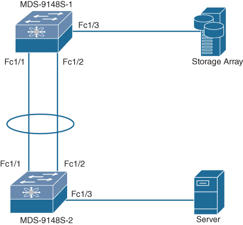
Figure 7-30 Sample Topology for Zoning Creation and Verification
Example 7-5 Zoning Creation and Verification on MDS-9148S Switch
! Checking current mode of Zoning.
MDS-9148S-1(config)# show zone status vsan 11
VSAN: 11 default-zone: deny distribute: active only Interop: default
    mode: basic merge-control: allow
    session:  none
    hard-zoning: enabled broadcast: unsupported
    smart-zoning: disabled
    rscn-format: fabric-address
    activation overwrite control: disabled
Default zone:
    qos: none broadcast: unsupported ronly: unsupported
Full Zoning Database :
    DB size: 124 bytes
    Zonesets:  0 Zones: 0 Aliases: 0
Active Zoning Database :
    Database Not Available
Current Total Zone DB Usage: 124 / 2097152 bytes (0 % used)
Pending (Session) DB size:
    Full DB Copy size: n/a
    Active DB Copy size: n/a
SFC size: 124 / 2097152 bytes (0 % used)
Status:

! Checking flogi database on MDS-9148S-1 for fabric login of Storage Array
MDS-9148S-1(config)# show flogi database
--------------------------------------------------------------------------------
INTERFACE    VSAN   FCID       PORT NAME                 NODE NAME
--------------------------------------------------------------------------------
fc1/3         11    0x010000   50:0a:09:83:81:aa:aa:01   50:0a:09:80:81:aa:aa:01

Total number of flogi = 1.

! Checking fcns database on MDS-9148S-1 to verify fabric login of both Storage Array and Server
MDS-9148S-1(config)# show fcns database

VSAN 11:
-----------------------------------------------------------------------------
FCID      TYPE    PWWN                       (VENDOR)     FC4-TYPE:FEATURE
-----------------------------------------------------------------------------
0x010000    N     50:0a:09:83:81:aa:aa:01    (NetApp)     scsi-fcp:target
0x470000    N     20:00:00:25:b5:10:70:10    (Cisco)      scsi-fcp:init fc-gs

Total number of entries = 2

! Configuring Zone with name ZONE_VSAN11 for vsan 11.
MDS-9148S-1(config)# zone name ZONE_VSAN11 vsan 11

! Checking the various methods by which zone member can be configured.
MDS-9148S-1(config-zone)# member ?
  device-alias       Add device-alias member to zone
  domain-id          Add member based on domain-id,port-number
  fcalias            Add fcalias to zone
  fcid               Add FCID member to zone
  fwwn               Add Fabric Port WWN member to zone
  interface          Add member based on interface
  ip-address         Add IP address member to zone
  pwwn               Add Port WWN member to zone
  symbolic-nodename  Add Symbolic Node Name member to zone
! Inserting FC target into Zone ZONE_VSAN11
MDS-9148S-1(config-zone)# member pwwn 50:0a:09:83:81:aa:aa:01
! Inserting FC initiator into Zone ZONE_VSAN11
MDS-9148S-1(config-zone)# member pwwn 20:00:00:25:b5:10:70:10
! Creating Zoneset with name ZONESET_VSAN11 for VSAN 11 with member ZONE_VSAN11
MDS-9148S-1(config-zone)# zoneset name ZONESET_VSAN11 vsan 11
MDS-9148S-1(config-zoneset)# member ZONE_VSAN11

! Verifying configured zone
MDS-9148S-1(config-zoneset)# show zone vsan 11
zone name ZONE_VSAN11 vsan 11
  pwwn 50:0a:09:83:81:aa:aa:01
  pwwn 20:00:00:25:b5:10:70:10

! Verifying active zone. Since we have not activated the zoneset, there is no active zone in the fabric.
MDS-9148S-1(config-zoneset)# show zone active vsan 11
Zone not present

! Enabling full zoneset distribution on each activation of zoneset
MDS-9148S-1(config-zoneset)# zoneset distribute full vsan 11

! Activating Zoneset
MDS-9148S-1(config)# zoneset activate name ZONESET_VSAN11 vsan 11
Zoneset activation initiated. check zone status

! Verifying active zone after zoneset activation
MDS-9148S-1(config)# show zone active vsan 11
zone name ZONE_VSAN11 vsan 11
* fcid 0x010000 [pwwn 50:0a:09:83:81:aa:aa:01]
* fcid 0x470000 [pwwn 20:00:00:25:b5:10:70:10]

! Changing zone mode from basic to enhanced
MDS-9148S-1(config)# zone mode enhanced vsan 11
WARNING: This command would distribute the zoning database of this switch throughout the fabric. Do you want to continue? (y/n) [n] y
Set zoning mode command initiated. Check zone status

! Verifying zone mode.
MDS-9148S-1(config)# show zone status vsan 11
VSAN: 11 default-zone: deny distribute: full Interop: default
    mode: enhanced merge-control: allow
    session:  none
    hard-zoning: enabled broadcast: unsupported
    smart-zoning: disabled
    rscn-format: fabric-address
    activation overwrite control: disabled
Default zone:
    qos: none broadcast: unsupported ronly: unsupported
Full Zoning Database :
    DB size: 280 bytes
    Zonesets:  1 Zones: 1 Aliases: 0 Attribute-groups: 1
Active Zoning Database :
    DB Size: 88 bytes
    Name: ZONESET_VSAN11 Zonesets: 1 Zones: 1
Current Total Zone DB Usage: 368 / 2097152 bytes (0 % used)
Pending (Session) DB size:
    Full DB Copy size: 0 bytes
    Active DB Copy size: 0 bytes
SFC size: 0 / 2097152 bytes (0 % used)
Status: Set zoning mode complete at 04:21:45 UTC Jul 23 2019
MDS-9148S-1(config)#
Device Alias
Cisco SAN switches support Distributed Device Alias Services (device aliases) on a per-VSAN basis and on a fabric-wide basis. Device alias distribution allows you to move host bus adapters (HBAs) between VSANs without manually re-entering alias names.
While the port WWN (pWWN) of a device has to be specified to configure different features (zoning, QoS, and port security) in a SAN switch, you must assign the correct device name each time you configure these features. An incorrect device name may cause unexpected results. You can avoid this if you define a user-friendly name for a pWWN and use this name in all of the configuration commands, as required. These user-friendly names are called device aliases.
Device Alias Features
Device aliases have the following features:
• The device alias information is independent of the VSAN configuration.
• The device alias configuration and distribution are independent of the zone server and the zone server database.
• You can import legacy zone alias configurations without losing data.
• The device alias application uses the Cisco Fabric Services (CFS) infrastructure to enable efficient database management and distribution. Device aliases use the coordinated distribution mode and the fabric-wide distribution scope.
• Device aliases support basic and enhanced modes.
• Device aliases used to configure zones, IVR zones, or port security features are displayed automatically with their respective pWWNs in the show command output.
Device aliases can be assigned only to pWWNs. There must be a one-to-one relationship between the pWWN and the device alias that maps to it.
A device alias name is restricted to 64 alphanumeric characters and may include one or more of the following characters:
• a to z and A to Z (Device alias names must begin with an alphabetic character—a to z or A to Z.)
• 1 to 9
• - (hyphen) and _ (underscore)
• $ (dollar sign) and ^ (up caret)
Device Alias Modes
A device alias supports the following two modes:
• Basic mode: When operating in basic mode, which is the default, the device alias is immediately expanded to a pWWN. This operation continues until the mode is changed to enhanced. In basic mode, when device aliases are changed to point to a new HBA, for example, that change is not reflected in the zone server. Users must remove the previous HBA’s pWWN, add the new HBA’s pWWN, and then reactivate the zone set.
• Enhanced mode: When operating in enhanced mode, applications accept a device alias name in its native format. Instead of expanding the device alias to a pWWN, the device alias name is stored in the configuration and distributed in its native device alias format. So, applications such as zone server, PSM, or DPVM can automatically keep track of the device alias membership changes and enforce them accordingly. The primary benefit of operating in enhanced mode is that you have a single point of change.
Whenever you change device alias modes, the change is distributed to other switches in the network only if device alias distribution is enabled, or on. Otherwise, the mode change takes place only on the local switch.
If two fabrics running in different device alias modes are joined together, the device alias merge fails. There is no automatic conversion to one mode or the other during the merge process. In this situation, you must select one mode over the other. Before changing from enhanced to basic mode, you must first explicitly remove all native device alias-based configurations from both local and remote switches or replace all device alias-based configuration members with the corresponding pWWN. If you remove a device alias from the device alias database, all applications automatically stop enforcing the corresponding device alias.
Renaming the device alias not only changes the device alias name in the device alias database but also replaces the corresponding device alias configuration in all of the applications. When a new device alias is added to the device alias database, and the application configuration is present on that device alias, it automatically takes effect.
Device Alias Distribution
By default, device alias distribution is enabled. The device alias feature uses CFS to distribute the modifications to all switches in a fabric.
If device alias distribution is disabled, database changes are not distributed to the switches in the fabric. The same changes would have to be performed manually on all switches in the fabric to keep the device alias database up-to-date. Database changes immediately take effect, so there would also not be any pending database and commit or abort operations. If you have not committed the changes and you disable distribution, a commit task will fail. But if you modify the device alias configuration, you will need to commit or discard the changes because the fabric remains locked during this period. Device alias database changes are validated with the applications. If any of the applications cannot accept the device alias database changes, those changes will be rejected; this applies to device alias database changes resulting from either a commit or merge operation.
![]()
The device alias feature uses two databases to accept and implement device alias configurations.
• Effective database: This is the database currently used by the fabric.
• Pending database: Your subsequent device alias configuration changes are stored in the pending database.
When you perform any device alias configuration task (regardless of which device alias task), the fabric is automatically locked for the device alias feature. After you lock the fabric, no other user can make any configuration changes to this feature. A copy of the effective database is obtained and used as the pending database. Subsequent modifications are made to the pending database. The pending database remains in use until you commit the modifications to the pending database or discard (abort) the changes to the pending database.
If you commit the changes made to the pending database, the following events occur:
• The pending database content overwrites the effective database content.
• The pending database is distributed to the switches in the fabric, and the effective database on those switches is overwritten with the new changes.
• The pending database is emptied of its contents.
• The fabric lock is released for this feature.
If you discard the changes made to the pending database, the following events occur:
• The effective database contents remain unaffected.
• The pending database is emptied of its contents.
• The fabric lock is released for this feature.
You can use locking operations (clear, commit, abort) only when device alias distribution is enabled. If you have performed a device alias task and have forgotten to release the lock by either committing or discarding the changes, an administrator can release the lock from any switch in the fabric. If the administrator performs this task, your changes to the pending database are discarded and the fabric lock is released. The changes are only available in the volatile directory and may be discarded if the switch is restarted.
If a switch with an existing device alias database is being added to an existing fabric, conflicts might arise if the same device alias name is used but with different pWWNs in the two fabrics, or if the same pWWN is used but with different device alias names. To resolve the merge status, use the show device-alias merge status and show cfs merge status name device-alias commands to verify the status of the merge. Use the show device-alias merge conflicts command to display the device alias and pWWNs that are causing a merge failure.
Zone Aliases (FC Aliases) Versus Device Aliases
Legacy zone aliases, also called FC aliases, which are used in zoning configuration, are different from device aliases. Table 7-12 compares the configuration differences between zone-based alias configuration and device alias configuration.
Table 7-12 Comparison Between Zone Aliases and Device Aliases

You can import legacy zone alias configurations to use the device alias feature without losing data, if each zone alias has only one member with type pWWN, and the name and definition of the zone alias are not the same as any existing device alias name.
Table 7-13 summarizes the NX-OS CLI commands that are related to device alias configuration and verification.
![]()
Table 7-13 Summary of NX-OS CLI Commands for Device Alias Configuration and Verification

Example 7-6 shows how to configure and verify the device alias on the sample topology shown in Figure 7-31.

Figure 7-31 Sample Topology for Device Alias Configuration and Verification
Example 7-6 Device Alias Creation and Verification on MDS-9148S Switch
! Setting the Device Alias mode to enhanced and committing the changes.
MDS-9148S(config)# device-alias mode enhanced
MDS-9148S(config)# device-alias commit
WARNING: Device-alias DB is empty in this switch. Initiating a commit from this switch will clear [wipe out] Device-alias DB across all the switches in the fabric, losing Device-alias full DB config permanently. Do you want to continue? (y/n) [n] y

! Verifying the flogi database to configure Device Alias for Storage pWWN.
MDS-9148S(config)# show flogi database
--------------------------------------------------------------------------------
INTERFACE     VSAN    FCID      PORT NAME               NODE NAME
--------------------------------------------------------------------------------
fc1/3          11     0x010000  50:0a:09:82:80:aa:aa:01 50:0a:09:80:80:aa:aa:01

Total number of flogi = 1.
! Configuring device alias for Storage pwwn as STORAGE
MDS-9148S(config)# device-alias database
MDS-9148S(config-device-alias-db)# device-alias name STORAGE pwwn 50:0a:09:82:80:aa:aa:01

! Since we have not committed the changes, the device alias will show up only as pending configuration and not in device-alias active database
MDS-9148S(config-device-alias-db)# show device-alias database
There are no entries in the database
MDS-9148S(config-device-alias-db)# show device-alias pending
device-alias name STORAGE pwwn 50:0a:09:82:80:aa:aa:01

Total number of entries = 1

! Once we commit the changes, STORAGE device alias is populated in both device-alias database and flogi database.
MDS-9148S(config-device-alias-db)# device-alias commit
MDS-9148S(config)# show device-alias database
device-alias name STORAGE pwwn 50:0a:09:82:80:aa:aa:01

Total number of entries = 1
MDS-9148S(config)# show flogi database
--------------------------------------------------------------------------------
INTERFACE    VSAN    FCID      PORT NAME               NODE NAME
--------------------------------------------------------------------------------
fc1/3         11     0x010000  50:0a:09:82:80:aa:aa:01 50:0a:09:80:80:aa:aa:01
                                      [STORAGE]
Total number of flogi = 1.
! Verifying Device Alias mode.
MDS-9148S(config)# show device-alias status
Fabric Distribution : Enabled
Database:- Device Aliases 1  Mode: Enhanced
           Checksum: 0xcf406e8ea08acd95f3de38e8541a311
MDS-9148S(config)#
NPIV and NPV
In fabric mode, the NX-OS switches provide the standard Fibre Channel switching capability and features. In this mode, each switch that joins a SAN is assigned a domain ID. Each SAN (or VSAN) supports a maximum of 239 domain IDs, so the SAN has a limit of 239 switches. In a SAN topology with a large number of edge switches, the SAN may need to grow beyond this limit. N port virtualization (NPV) alleviates the domain ID limit by sharing the domain ID of the core switch among multiple edge switches.
![]()
The NPV core switch, with the N port identifier virtualization (NPIV) feature enabled, provides a means to assign multiple FCIDs to a single N port. This feature allows multiple applications on the N port to use different identifiers and allows access control, zoning, and port security to be implemented at the application level.
An NPV edge switch relays all traffic from server-side ports to the core switch. The core switch provides F port functionality (such as login and port security) and all the Fibre Channel switching capabilities. The edge switch shares the domain ID of the core switch. The edge switch appears as a Fibre Channel host to the core switch and as a regular Fibre Channel switch to its connected devices.
Figure 7-32 shows an interface-level view of an NPV configuration.
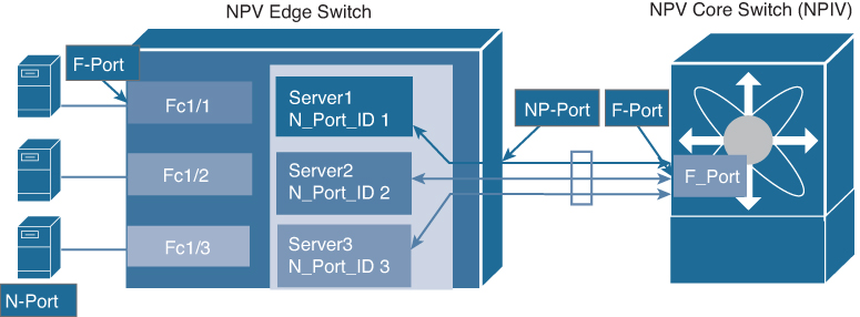
Figure 7-32 NPV Interface Configuration
In NPV mode, a subset of fabric mode CLI commands and functionality is supported. For example, commands related to fabric login and name server registration are not required on the edge switch because these functions are provided in the core switch. To display the fabric login and name server registration databases, you must enter the show flogi database and show fcns database commands on the core switch.
All interfaces from the edge switch to the core switch are configured as proxy N ports (NP ports). An NP uplink is a connection from an NP port on the edge switch to an F port on the core switch. When an NP uplink is established, the edge switch sends a fabric login message (FLOGI) to the core switch, and then (if the FLOGI is successful) it registers itself with the name server on the core switch. Subsequent FLOGIs from end devices connected to this NP uplink are converted to fabric discovery messages (FDISCs). In Cisco Nexus devices, NP uplink interfaces must be native Fibre Channel interfaces.
When an NP port becomes operational, the switch first logs itself in to the core switch by sending an FLOGI request (using the port WWN of the NP port). After completing the FLOGI request, the switch registers itself with the fabric name server on the core switch (using the symbolic port name of the NP port and the IP address of the edge switch).
Server interfaces are F ports on the edge switch that connect to the servers. A server interface may support multiple end devices by enabling the N port identifier virtualization (NPIV) feature on the core switch. NPIV provides a means to assign multiple FCIDs to a single N port, which allows the server to assign unique FCIDs to different applications. To use the NPIV feature, you have to enable the NPIV feature. Server interfaces are automatically distributed among the NP uplinks to the core switch. All of the end devices connected to a server interface are mapped to the same NP uplink. In Cisco Nexus devices, server interfaces can be physical or virtual Fibre Channel interfaces.
Note
Zoning is not enforced at the edge switch (rather, it is enforced on the core switch). Multiple devices attached to an edge switch log in through the same F port on the core, so they cannot be separated into different zones.
When you enable NPV on an edge switch using the npv enable command, the system configuration is erased and the switch reboots. After you enable NPV, you should configure the NP uplink interfaces and the server interfaces using the switchport mode NP and switchport mode F commands, respectively. You cannot configure NPV mode on a per-interface basis. NPV mode applies to the entire switch.
On NPV switches, by default, trunk mode is disabled. You can configure trunk mode as on (enabled), off (disabled), or auto (automatic). The trunk mode configuration at the two ends of an ISL, between two switches, determine the trunking state of the link and the port modes at both ends as listed in Table 7-14.
Table 7-14 Trunk Mode Status Between NPV and NPIV Switches

Table 7-15 summarizes the NX-OS CLI commands that are related to NPV and NPIV configuration and verification.
![]()
Table 7-15 Summary of NX-OS CLI Commands for NPV and NPIV Configuration and Verification

Example 7-7 shows how to configure and verify NPV and NPIV on the sample topology shown in Figure 7-33.
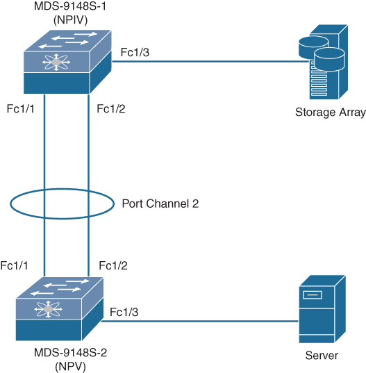
Figure 7-33 Sample Topology for NPV and NPIV Configuration and Verification
Example 7-7 NPV and NPIV Creation and Verification on MDS-9148S Switches
MDS-9148S-2: (NPV)
================
! Enabling Feature NPV.
MDS-9148S-2(config)# feature npv
Verify that boot variables are set and the changes are saved. Changing to npv mode erases the current configuration and reboots the switch in npv mode. Do you want to continue? (y/n):y

! Configuring fc 1/1 and fc 1/2 interfaces as part of Port Channel 2.
MDS-9148S-2(config-if)# int fc 1/1, fc 1/2
MDS-9148S-2(config-if)# channel-group 2 force
fc1/1 fc1/2 added to port-channel 2 and disabled
please do the same operation on the switch at the other end of the port-channel,
then do “no shutdown” at both ends to bring it up
MDS-9148S-2(config-if)# no shut

! Configuring channel mode of Port Channel 2 as active mode and interface as NP port which indirectly configures fc 1/1 and fc 1/2 as NP port.
MDS-9148S-2(config-if)# int port-channel 2
MDS-9148S-2(config-if)# switchport mode np
MDS-9148S-2(config-if)# channel mode active
MDS-9148S-2(config-if)# no shut

! Checking status of Port Channel 2 for port mode and active interfaces
MDS-9148S-2# show interface port-channel 2
port-channel 2 is up
    Hardware is Fibre Channel
    Port WWN is 24:02:8c:60:4f:2d:de:c0
    Admin port mode is NP, trunk mode is off
    snmp link state traps are enabled
    Port mode is NP
    Port vsan is 11
    Speed is 16 Gbps
    1 minute input rate 0 bits/sec, 0 bytes/sec, 0 frames/sec
    1 minute output rate 0 bits/sec, 0 bytes/sec, 0 frames/sec
      111 frames input, 10496 bytes
        0 discards, 0 errors
        0 CRC,  0 unknown class
        0 too long, 0 too short
      90 frames output, 8732 bytes
        0 discards, 0 errors
      0 input OLS, 0 LRR, 0 NOS, 0 loop inits
      6 output OLS, 4 LRR, 0 NOS, 0 loop inits
    last clearing of “show interface” counters never
    Member[1] : fc1/1
    Member[2] : fc1/2
    Interface last changed at Mon Jul 22 05:35:04 2019

! Checking npv status for External interface and Server Interfaces status
MDS-9148S-2# show npv status

npiv is disabled

disruptive load balancing is disabled

External Interfaces:
====================
  Interface: port-channel 2, State: Up
        VSAN:   11, State: Up, FCID: 0x010100

  Number of External Interfaces: 1

Server Interfaces:
==================
  Interface: fc1/3, VSAN:   11, State: Up

  Number of Server Interfaces: 1

! Checking npv flogi-table to confirm the flogi for directly connected Server

MDS-9148S-2# show npv flogi-table
---------------------------------------------------------------------------------------------
SERVER                                                                             EXTERNAL
INTERFACE   VSAN    FCID       PORT NAME                 NODE NAME                 INTERFACE
---------------------------------------------------------------------------------------------
fc1/3        11     0x010101   20:00:00:25:b5:10:70:10   21:00:00:25:b5:10:70:10     po2

Total number of flogi = 1.

MDS-9148S-1: (NPIV)
=================

! Enabling feature npiv.
MDS-9148S-1(config)# feature npiv
! Configuring interfaces fc 1/1 and fc 1/2 as part of port channel 2
MDS-9148S-1(config)# int fc 1/1, fc 1/2
MDS-9148S-1(config-if)# channel-group 2 force
MDS-9148S-1(config-if)# no shutdown
! Configuring port channel 2 interface as F port with channel mode active
MDS-9148S-1(config-if)# int port-channel 2
MDS-9148S-1(config-if)# switchport mode F
MDS-9148S-1(config-if)# channel mode active
MDS-9148S-1(config-if)# no shut
! Verifying status of port channel 2 for port mode and active interfaces
MDS-9148S-1(config)# show interface port-channel 2
port-channel2 is up
    Hardware is Fibre Channel
    Port WWN is 24:02:00:de:fb:25:b8:80
    Admin port mode is F, trunk mode is on
    snmp link state traps are enabled
    Port mode is F
    Port vsan is 11
    Speed is 16 Gbps
    Logical type is core
    5 minutes input rate 160 bits/sec,20 bytes/sec, 0 frames/sec
    5 minutes output rate 192 bits/sec,24 bytes/sec, 0 frames/sec
      1022 frames input,90236 bytes
        0 discards,0 errors
        0 invalid CRC/FCS,0 unknown class
        0 too long,0 too short
      1117 frames output,96364 bytes
        0 discards,0 errors
      42 input OLS,17  LRR,0 NOS,0 loop inits
      50 output OLS,44 LRR, 30 NOS, 0 loop inits
    Member[1] : fc1/1     [up] *
    Member[2] : fc1/2     [up]
    Interface last changed at Tue Jul 23 06:49:24 2019

! Verifying npiv status
MDS-9148S-1# show npiv status
NPIV is enabled

! Verifying flogi and fcns table to see if MDS-9148S-2 has logged in to NPIV router. The second entry in both the following tables belong to MDS-9148S-2 switch.

MDS-9148S-1(config)# show flogi database
------------------------------------------------------------------------------------------
INTERFACE        VSAN     FCID        PORT NAME                  NODE NAME
------------------------------------------------------------------------------------------
fc1/3             11      0x010000    50:0a:09:83:81:aa:aa:01    50:0a:09:80:81:aa:aa:01
port-channel2     11      0x010100    24:02:8c:60:4f:2d:de:c0    20:0b:8c:60:4f:2d:de:c1
port-channel2     11      0x010101    20:00:00:25:b5:10:70:10    21:00:00:25:b5:10:70:10

Total number of flogi = 3.

MDS-9148S-1(config)# show fcns database

VSAN 11:
---------------------------------------------------------------------------------
FCID         TYPE     PWWN                      (VENDOR)    FC4-TYPE:FEATURE
---------------------------------------------------------------------------------
0x010000      N       50:0a:09:83:81:aa:aa:01   (NetApp)    scsi-fcp:target
0x010100      N       24:02:8c:60:4f:2d:de:c0   (Cisco)     npv
0x010101      N       20:00:00:25:b5:10:70:10   (Cisco)     scsi-fcp:init fc-gs

Total number of entries = 3
Exam Preparation Tasks
As mentioned in the section “How to Use This Book” in the Introduction, you have a couple of choices for exam preparation: the exercises here, Chapter 20, “Final Preparation,” and the exam simulation questions in the Pearson Test Prep software online.
Review All Key Topics
Review the most important topics in the chapter, noted with the key topic icon in the outer margin of the page. Table 7-16 lists a reference to these key topics and the page numbers on which each is found.
![]()
Table 7-16 Key Topics for Chapter 7


Memory Tables
Print a copy of Appendix C, “Memory Tables” (found on the companion website), or at least the section for this chapter, and complete the tables and lists from memory. Appendix D, “Memory Tables Answer Key,” also on the companion website, includes completed tables and lists to check your work.
Define Key Terms
Define the following key terms from this chapter, and check your answers in the Glossary.
virtual storage-area network (VSAN)
zoning
port login (PLOGI)
fabric login (FLOGI)
process login (PRLI)
Cisco Fabric Services (CFS)
Dynamic Port VSAN Membership (DPVM)
F port channel trunk
host bus adapter (HBA)
Exchange Peer Parameter (EPP)
switch World Wide Name (sWWN)
port World Wide Name (pWWN)
N port virtualization (NPV)
N port identifier virtualization (NPIV)
inter-switch links (ISLs)
World Wide Port Name (WWPN)
World Wide Node Name (WWNN)
fan-in ratio
fan-out ratio
References
Design a Reliable and Highly Available Fibre Channel SAN White Paper: https://www.cisco.com/c/en/us/products/collateral/storage-networking/mds-9700-series-multilayer-directors/white-paper-c11-738426.html
Relevant Cisco Live Presentations: https://www.ciscolive.com/
Large SAN Design Best Practices White Paper: https://www.cisco.com/c/en/us/products/collateral/storage-networking/mds-9500-series-multilayer-directors/white_paper_C11-515630.html
Cisco MDS 9000 Series Interfaces Configuration Guide, Release 8.x: https://www.cisco.com/c/en/us/td/docs/switches/datacenter/mds9000/sw/8_x/config/interfaces/cisco_mds9000_interfaces_config_guide_8x.html
Gustavo A. A. Santana, Data Center Virtualization Fundamentals (Indianapolis: Cisco Press, 2014).
Cisco MDS 9000 Series Fabric Configuration Guide, Release 8.x: https://www.cisco.com/c/en/us/td/docs/switches/datacenter/mds9000/sw/8_x/config/fabric/cisco_mds9000_fabric_config_guide_8x.html
Cisco MDS 9000 Series System Management Configuration Guide, Release 8.x: https://www.cisco.com/c/en/us/td/docs/switches/datacenter/mds9000/sw/8_x/config/system-management/cisco_mds9000_system_management_config_guide_8x.html
Fibre Channel Fabric Address Manager MIB: https://tools.ietf.org/html/draft-desanti-fc-domain-manager-02
Relevant Cisco Community Pages: https://community.cisco.com
Cisco MDS 9000 Series Fabric Configuration Guide, Release 8.x: https://www.cisco.com/c/en/us/td/docs/switches/datacenter/mds9000/sw/8_x/config/fabric/cisco_mds9000_fabric_config_guide_8x.html
Cisco Nexus 5600 Series NX-OS SAN Switching Configuration Guide, Release 7.x: https://www.cisco.com/c/en/us/td/docs/switches/datacenter/nexus5600/sw/san_switching/7x/b_5600_SAN_Switching_Config_7x.html