
Chapter 17. Network Security
Securing network access and data center devices has never been a simple task. However, it’s always challenging and hard to define user access privileges and apply appropriate network policies, network controls, and so on. The new network security module is Zero Trust (ZT); it is a guiding concept that implies the network is always assumed to be hostile and both external and internal threats exist at all times. Zero Trust mandates a “never trust, always verify, enforce least privilege” approach, granting least privilege access based on a dynamic evaluation of the trustworthiness of users and their devices and of any transaction risk before they are allowed to connect to network resources.
This chapter covers the following key topics:
• Authentication, Authorization, and Accounting (AAA): This section discusses the Cisco NX-OS authentication, authorization, and accounting concepts. Later in this section, we discuss server groups, server monitoring, remote and local AAA services, and AAA network configurations.
• Role-Based Access Control (RBAC): This section discusses user roles, rules, and policies related to user roles and includes RBAC commands in a sample configuration.
• Nexus First-Hop Security: This section discusses Nexus first-hop security, including DAI, DHCP snooping, and port security; it also includes configuration examples and verifications.
• Nexus Control Plane Policing (CoPP): This section discusses Nexus Control Plane Policing (CoPP) usage, recommendations, and configuration; it also includes a customized CoPP example.
• Cisco ACI Contracts: This section discusses Application Centric Infrastructure (ACI) contracts and microsegmentation, and includes graphical user interface (GUI) and command-line interface (CLI) configuration examples.
“Do I Know This Already?” Quiz
The “Do I Know This Already?” quiz enables you to assess whether you should read this entire chapter thoroughly or jump to the “Exam Preparation Tasks” section. If you are in doubt about your answers to these questions or your own assessment of your knowledge of the topics, read the entire chapter. Table 17-1 lists the major headings in this chapter and their corresponding “Do I Know This Already?” quiz questions. You can find the answers in Appendix A, “Answers to the ‘Do I Know This Already?’ Quizzes.”
Table 17-1 “Do I Know This Already?” Section-to-Question Mapping”

Caution
The goal of self-assessment is to gauge your mastery of the topics in this chapter. If you do not know the answer to a question or are only partially sure of the answer, you should mark that question as wrong for purposes of the self-assessment. Giving yourself credit for an answer you correctly guess skews your self-assessment results and might provide you with a false sense of security.
1. What are the most common AAA protocols? (Choose two answers.)
a. TCP/IP
b. RADIUS
c. TACACS+
d. LDAP
2. What command would you enter to set up authentication on your router to query the TACACS servers and, if unable to communicate to the servers, authenticate from the local password?
a. aaa authentication login default group radius enable
b. aaa authentication login default group tacacs+ local
c. aaa authentication login default group tacacs+ enable
d. aaa authentication login default group tacacs+ none
3. What ports are used by RADIUS protocols? (Choose two answers.)
a. UDP 49
b. UDP 1645/1646
c. TCP 1645/1646
d. UDP 1812/1813
4. By default, the user accounts without an administrator role can access the ____________. (Choose two answers.)
a. show command
b. config terminal command
c. Interface <interface name>
d. Router OSPF
5. When you enable DHCP snooping, what does an untrusted port filter out?
a. DHCP replies from a legitimate DHCP server
b. DHCP replies from a rogue server
c. DHCP requests from a legitimate client
d. DHCP requests from rogue clients
6. Dynamic ARP inspections help mitigate an attack based on which one of the following parameters with an ARP reply packet?
a. Source IP address
b. MAC address
c. Destination IP address
d. Sequence number
7. By default, how many MAC addresses are permitted to be learned on a switch port with port security enabled?
a. Eight
b. Four
c. Two
d. One
8. What does Control Plane Policing (CoPP) protect?
a. The CPU against DDoS
b. Memory against memory leaks
c. The NX-OS against unauthorized access
d. All of the above
9. Microsegmentation improves network performance.
a. True
b. False
10. If no contract is applied between intra-endpoints, no traffic flow is allowed between the provider and the consumer.
a. True
b. False
Foundation Topics
Authentication, Authorization, and Accounting
Authentication, Authorization, and Accounting (AAA) is a protocol used to secure access to a Cisco Nexus device. The AAA model answers three questions:
1. Who is on the network (authentication)?
2. What are they allowed to do on the network (authorization)?
3. What have they been doing on the network (accounting)?
• Authentication: Identifies users, including the login and password dialog, challenge and response, messaging support, and, depending on the security protocol that you select, encryption. Authentication is the process of verifying the identity of the person or device accessing the Cisco NX-OS device, which is based on the user ID and password combination provided by the entity trying to access the Cisco NX-OS device. Cisco NX-OS devices allow you to perform local authentication (using the local lookup database) or remote authentication (using one or more RADIUS or TACACS+ servers).
• Authorization: Provides access control. Authorization is the process of assembling a set of attributes that describe what the user is authorized to perform. Authorization in the Cisco NX-OS software is provided by attributes that are downloaded from AAA servers. Remote security servers, such as RADIUS and TACACS+, authorize users for specific rights by associating attribute-value (AV) pairs, which define those rights with the appropriate user.
• Accounting: Provides the method for collecting information, logging the information locally, and sending the information to the AAA server for billing, auditing, and reporting. The accounting feature tracks and maintains a log of every management session used to access the Cisco NX-OS device. You can use this information to generate reports for troubleshooting and auditing purposes. You can store accounting logs locally or send them to remote AAA servers.
AAA allows for a granular approach to securing the devices by setting policies for either a group or individual and by allowing the administrator to use different method lists for different access types. For example, the engineer could create a method list for authentication that states the TACACS+ server at 10.10.10.1 should be used for console access and should fall back to the local database. A different method list can be used for the VTY lines stating that a RADIUS server should be used and fall back to the local database. If the default method list is used, it applies to all device access methods. AAA can be used with both RADIUS and TACACS+ servers to provide secure services. There are some noteworthy differences between the two protocols:
1. TACACS+ uses TCP port 49 for communication, whereas RADIUS uses UDP port 1645/1646 or 1812/1813.
2. TACACS+ encrypts the entire contents of the packet. RADIUS encrypts only the password.
3. TACACS+ is more flexible in the protocols that it can support.
4. TACACS+ is Cisco proprietary. RADIUS is defined in RFC 2138 and is an open standard.
Nexus devices support local and remote AAA. Remote AAA services are provided through RADIUS and TACACS+ protocols. Remote services have the following advantages over local AAA services:
• It is easier to manage user password lists for each Cisco NX-OS device in the fabric.
• AAA servers are already deployed widely across enterprises and can be easily used for AAA services.
• You can centrally manage the accounting log for all Cisco NX-OS devices in the fabric.
• It is easier to manage user attributes for each Cisco NX-OS device in the fabric than using the local databases on the Cisco NX-OS devices.
You can specify remote AAA servers for authentication, authorization, and accounting using server groups. A server group is a set of remote AAA servers that implement the same AAA protocol. The purpose of a server group is to provide for failover servers in case a remote AAA server fails to respond. If the first remote server in the group fails to respond, the next remote server in the group is tried until one of the servers sends a response. If all the AAA servers in the server group fail to respond, that server group option is considered a failure. If required, you can specify multiple server groups. If the Cisco NX-OS device encounters errors from the servers in the first group, it tries the servers in the next server group.
Configuring AAA on the command line is fairly simple, but the commands can be quite lengthy depending on the optional parameters used within the command set itself.
AAA Service Configuration Options
AAA configuration in Cisco NX-OS devices is service based, which means that you can have separate AAA configurations for the following services:
• User Telnet or Secure Shell (SSH) login authentication
• Console login authentication
• Cisco TrustSec authentication
• 802.1X authentication
• Extensible Authentication Protocol over User Datagram Protocol (EAPoUDP) authentication for Network Admission Control (NAC)
• User management session accounting
• 802.1X accounting
Table 17-2 shows some of the most-used AAA service configuration commands. For a full list of commands, refer to the Nexus Security Configuration Guide links in the “Reference” section at the end of the chapter.
Table 17-2 AAA Service Global Configuration Commands

You can specify the following authentication methods for the AAA services:
• All RADIUS servers: Uses the global pool of RADIUS servers for authentication.
• Specific Server Groups: Specifies a single remote group or specific remote groups.
• Local: Uses the local username or password database for authentication.
• None: Specifies that no AAA authentication be used.
Note
If you specify the All RADIUS servers method rather than a specified server group method, the Cisco NX-OS device chooses the RADIUS server from the global pool of configured RADIUS servers, in the order of configuration. Servers from this global pool are the servers that can be selectively configured in a RADIUS server group on the Cisco NX-OS device.
Authentication and Authorization User Login Process
The authentication and authorization process is as follows:
1. When a user logs in to the required Cisco NX-OS device, that user can use the Telnet, SSH, or console login option.
Note
It is recommended that you disable the Telnet service and only allow SSH for remote access. Telnet is insecure because it sends passwords and commands in clear text.
2. If you configured the AAA server groups using the server group authentication method, the Cisco NX-OS device sends an authentication request to the first AAA server in the group as follows:
• If the AAA server fails to respond, the next AAA server is tried and so on until the remote server responds to the authentication request.
• If all AAA servers in the server group fail to respond, the servers in the next server group are tried.
• If all configured methods fail, the local database is used for authentication.
3. If the Cisco NX-OS device successfully authenticates users through a remote AAA server, the following possibilities apply:
• If the AAA server protocol is RADIUS, user roles specified in the cisco-av-pair attribute are downloaded with an authentication response.
• If the AAA server protocol is TACACS+, another request is sent to the same server to get the user roles specified as custom attributes for the shell.
4. If the username and password are successfully authenticated locally, the Cisco NX-OS device logs in the user and assigns the roles configured in the local database.
For the Nexus 7000 Series with virtual device context (VDC), all AAA configurations and operations are local to the VDC, except the default console methods and the AAA accounting log. The configuration and operation of the AAA authentication methods for the console login apply only to the default VDC. The AAA accounting log is only in the default VDC. You can display the contents from any VDC, but you must clear it in the default VDC.
AAA NX-OS Configurations
The Cisco NX-OS feature does not require a license. Any feature not included in a license package is bundled with the Cisco NX-OS system images and is provided at no extra charge to you. It is recommended that you configure AAA with a remote server. Remote AAA servers have the following prerequisites:
• Ensure that the Cisco NX-OS device is configured as a client of the AAA servers.
• Ensure that the secret key is configured on the Cisco NX-OS device and the remote AAA servers.
• Ensure that the remote server responds to AAA requests from the Cisco NX-OS device.
Note
If you have a user account configured on a local Cisco NX-OS device that has the same name as a remote user account on an AAA server, the Cisco NX-OS software applies the user roles for the local user account to the remote user, not the user roles configured on the AAA server.
Table 17-3 lists the default settings for AAA parameters. You can alter these parameters as necessary.
Table 17-3 Default Settings for AAA Parameters

Tables 17-4 through 17-6 show some of the most-used AAA configuration commands. For a full list of commands, refer to the Nexus Security Configuration Guide links in the “References” section at the end of this chapter.
Table 17-4 Global AAA Commands


Table 17-5 AAA Passphrase and Locking User Accounts Commands

Table 17-6 AAA Verification and Monitoring Commands

Example 17-1 shows how to configure the AAA login and console using a remote RADIUS server with a fallback option set to local.
Example 17-1 NX-OS AAA Configuration
Switch(config)# radius-server host 10.10.10.134 key cisco123
switch(config)# aaa group server radius radius-1
switch(config-radius)# server 10.10.10.134

switch(config)# aaa authentication login default group radius-1
switch(config)# aaa authentication login console group radius-1
switch(config)# aaa authentication login default fallback error local
switch(config)# aaa accounting default group radius-1
Role-Based Access Control
One of the most challenging problems in managing a large data center is the complexity of security administration. Role-based access control (RBAC) allows you to determine the commands and resources available to each user. In RBAC, users are associated with roles and rules. User roles determine a user’s privileges, and a rule defines what operations the role allows the user to perform.
You can create and manage user accounts and assign roles that limit access to operations on the Cisco NX-OS device. RBAC allows you to define the rules for an assigned role that restricts the authorization that the user has to access management operations.
You can configure up to a maximum of 256 user accounts. By default, the user account does not expire unless you explicitly configure it to expire. The expire option determines the date when the user account is disabled. For Nexus 7000 Series with virtual device context (VDC), users can have user accounts on multiple VDCs. These users can move between VDCs after an initial connection to a VDC. The Cisco NX-OS software provides two default user accounts: admin and admin backup.
Note
The following words are reserved and cannot be used to configure users: bin, daemon, adm, lp, sync, shutdown, halt, mail, news, uucp, operator, games, gopher, ftp, nobody, nscd, mailnull, root, rpc, rpcuser, xfs, gdm, mtsuser, ftpuser, man, and sys.
Note
The Cisco NX-OS software does not support all numeric usernames, whether created with TACACS+ or RADIUS, or created locally. Local users with all-numeric names cannot be created. If an all-numeric username exists on the AAA server and is entered during login, the user is not logged in.
Note
Usernames must begin with an alphanumeric character and can contain only these special characters: ( + = . _ -). The # and ! symbols are not supported. If the username contains characters that are not allowed, the specified user is unable to log in.
A good security practice is to enable password-strength checking to force users to use strong passwords. A strong password has the following characteristics:
• Is at least eight characters long.
• Does not contain many consecutive characters (such as abcd).
• Does not contain many repeating characters (such as aaabbb).
• Does not contain dictionary words.
• Does not contain proper names.
• Contains both uppercase and lowercase characters.
• Contains numbers.
The following are examples of strong passwords:
• M!C15c0!@345
• 2020Ccn980ok
• D@taC3ntr3Ex@m
If a password is trivial (such as a short, easy-to-decipher password), the Cisco NX-OS software rejects the password configuration if password-strength checking is enabled. Be sure to configure a strong password as shown in the preceding examples. Passwords are case sensitive.
Note
Clear-text passwords cannot contain dollar signs ($) or spaces anywhere in the password. Also, they cannot include these special characters at the beginning of the password: quotation marks (“ or ‘), vertical bars (|), or right-angle brackets (>).
Note
All printable ASCII characters are supported in the password string if they are enclosed in quotation marks.
NX-OS User Roles and Rules
User roles contain rules that define the operations allowed for the user who is assigned the role. Each user role can contain multiple rules, and each user can have multiple roles. For example, if role1 allows access only to configuration operations, and role2 allows access only to debug operations, users who belong to both role1 and role2 can access configuration and debug operations. You can also limit access to specific Virtual Routing and Forwarding (VRF) instances, VLANs, and interfaces.
The Cisco NX-OS software provides the following user roles:
• network-admin: Complete read-and-write access to the entire Cisco NX-OS device (for Nexus 7000, only available in the default VDC)
• network-operator: Complete read access to the entire Cisco NX-OS device (for Nexus 7000, only available in the default VDC)
• vdc-admin: Read-and-write access limited to a VDC
• vdc-operator: Read access limited to a VDC
Note
Only Cisco Nexus 7000 Series switches support multiple VDCs; however, the vdc-operator role is available on all Nexus switches and has the same privileges and limitations as the network-operator role.
Note
All Cisco Nexus Series switches except Nexus 7000 support a single VDC; consequently the vdc-admin has the same privileges and limitations as the network-admin.
By default, the user accounts without an administrator role can access only the show, exit, end, and configure terminal commands. You can add rules to allow users to configure features.
Note
If you belong to multiple roles, you can execute a combination of all the commands permitted by these roles. Access to a command takes priority over being denied access to a command. For example, suppose a user has role1, which is denied access to the configuration commands. However, the user also has role2, which has access to the configuration commands. In this case, the user has access to the configuration commands.
Note
Only the network-admin user can perform a checkpoint or rollback in the RBAC roles. Though other users have these commands as a permit rule in their role, user access is denied when you try to execute these commands.
The rule is the basic element of a role. A rule defines what operations the role allows the user to perform. You can apply rules for the following parameters:
• Command: A command or group of commands defined in a regular expression
• Feature: A command or group of commands defined in a regular expression
• Feature group: Default or user-defined group of features
• OID: An SNMP object identifier (OID)
The command, feature, and feature group parameters create a hierarchical relationship. The most basic control parameter is the command. The next control parameter is the feature, which represents all commands associated with the feature. The last control parameter is the feature group. The feature group combines related features and allows you to easily manage the rules. The Cisco NX-OS software also supports the predefined feature group L3 that you can use.
You can configure up to 256 rules for each role. The user-specified rule number determines the order in which the rules are applied. Rules are applied in descending order. For example, if a role has three rules, rule 3 is applied before rule 2, which is applied before rule 1.
For Nexus 7000 with virtual device context, the users with the network-admin and network-operator roles can operate in all VDCs when logged in from the default VDC and use the switchto vdc command to access other VDCs. All other user roles are local to the VDC. Roles are not shared between VDCs. Each VDC maintains an independent user role database.
The following guidelines and limitations apply to the switchto vdc command:
• Only users with the network-admin or network-operator role can use the switchto vdc command. No other users are permitted to use it.
• No user can grant permission to another role to use the switchto vdc command.
• After a network-admin uses the switchto vdc command, this user becomes a vdc-admin for the new VDC. Similarly, after a network-operator uses the switchto vdc command, this user becomes a vdc-operator for the new VDC. Any other roles associated with the user are not valid after the switchto vdc command is entered.
• After a network-admin or network-operator uses the switchto vdc command, this user cannot use this command to switch to another VDC. The only option is to use the switchback command to return to the original VDC.
NX-OS RBAC Configurations
The RBAC feature does not require a license. Any feature not included in a license package is bundled with the Cisco NX-OS system images and is provided at no extra charge to you. RBAC configuration recommendations and limitations include the following:
• You can create up to 64 user-defined roles in a VDC in addition to the four default user roles in the default VDC and the two default user roles in the nondefault VDCs.
• You can add up to 256 rules to a user role.
• You can add up to 64 user-defined feature groups to a VDC in addition to the default feature group, L3.
• You can configure up to 256 users in a VDC.
• You can assign a maximum of 64 user roles to a user account.
• If you have a user account configured on the local Cisco NX-OS device that has the same name as a remote user account on an AAA server, the Cisco NX-OS software applies the user roles for the local user account to the remote user, not the user roles configured on the AAA server.
• You cannot delete the default admin and SNMP user accounts.
• You cannot remove the default user roles from the default admin user accounts.
• The network-operator and vdc-operator roles cannot run the show running-config and show startup-config commands.
• RBAC is not supported for traffic between F1 Series module ports and M1 Series module ports in the same VLAN.
• When you use the rule rule-id permit command command-string command, the command-string argument should be complete or it should contain an asterisk (*) after the command name—for example, show * or show running-config *.
• If you are adding more than one command in the command-string argument, the commands should be separated by a command separator (;), and whitespace should be added.
• When you are specifying interfaces, it is recommended that you specify the entire media type keyword such as Ethernet or loopback. However, if you are using the short form of the media type keyword, it should be followed by an asterisk (*)—for example, “rule 22 permit command show run int Ethernet4/1”, “rule 22 permit command show run int loopback1”, or “rule 22 permit command show run int eth*” . Rules that do not follow this guideline are not accepted—for example, “rule 22 permit command show run int Eth1/4” and “rule 22 permit command show run int loop1”.
Table 17-7 shows NX-OS user account default parameters. You can alter these parameters as necessary.
Table 17-7 Default User Accounts and RBAC Parameters

Tables 17-8 and 17-9 show some of the most-used user account and RBAC configuration commands. For a full list of commands, refer to the Nexus Security Configuration Guide links in the “References” section at the end of this chapter.
Table 17-8 User Account and RBAC Global Commands


Table 17-9 User Account and RBAC Verification Commands

Example 17-2 shows how to configure a user role named User-Role-1.
Example 17-2 Creating a User Role Named User-Role-1
role name User-Role-1
  rule 3 permit read-write feature l2nac
  rule 2 permit read-write feature dot1x
  rule 1 deny command clear *
Example 17-3 shows how to create a user role that can configure an interface to enable and show the Hot Standby Router Protocol (HSRP) and Gateway Load Balancing Protocol (GLBP). Rule 1 allows you to configure HSRP on an interface, rule 2 allows you to configure the config hsrp commands and enable the exec-level show and debug commands for HSRP, and rule 3 allows you to enable the exec-level show and debug glbp commands.
Example 17-3 Creating a User Role Named MyTest
role name MyTest
           rule 1 permit command config t; interface *; hsrp *
           rule 2 permit read-write feature hsrp
           rule 3 permit read feature glbp
Example 17-4 shows how to configure a user role that can configure only a specific interface (Interface E1/4).
Example 17-4 Creating a User Role Named Int_Eth1_4_only
role name Int_Eth1_4_only
  rule 1 permit command configure terminal; interface *
  interface policy deny
    permit interface Ethernet1/4
Example 17-5 shows how to configure a user role feature group to enable or disable specific features.
Example 17-5 Creating a User Group Named Security-features
role feature-group name Security-features
  feature radius
  feature tacacs
  feature vpc
  feature aaa
  feature bgp
  feature acl
  feature access-list
Example 17-6 shows how to configure a user account.
Example 17-6 Creating a User Account
username user1 password C1sc0@2020 role User-role-1
Example 17-7 shows how to add an OID rule to restrict access to part of the OID subtree.
![]()
Example 17-7 Creating a User Role Named User1
role name User1
               rule 1 permit read feature snmp
               rule 2 deny read oid 1.3.6.1.2.1.1.9

show role name User1

Role: User1
  Description: new role
  Vlan policy: permit (default)
  Interface policy: permit (default)
  Vrf policy: permit (default)
  -------------------------------------------------------------------
  Rule    Perm    Type        Scope               Entity
  -------------------------------------------------------------------
  2       deny    read        oid                 1.3.6.1.2.1.1.9
  1       permit  read        feature             snmp
Nexus First-Hop Security
Information theft can result from router impersonation (man-in-the-middle attacks), address theft, address spoofing, and remote address resolution cache exhaustion (denial-of-service attacks). These security breaches can come from malicious or misconfigured users and can severely disrupt Layer 2 domains and networks in general.
Nexus First-Hop Security (FHS) features enable better IPv4 and IPv6 link security and management over the Layer 2 links. In a service provider environment, these features closely control address assignment and derived operations, such as Duplicate Address Detection (DAD) and Address Resolution (AR).
The following supported FHS features secure the protocols and help build a secure endpoint database on the fabric leaf switches that are used to mitigate security threats such as MIM attacks and IP thefts:
• ARP inspection: Allows a network administrator to intercept, log, and discard ARP packets with invalid MAC address-to-IP address bindings.
• ND inspection: Learns and secures bindings for stateless autoconfiguration addresses in Layer 2 neighbor tables.
• DHCP inspection: Validates DHCP messages received from untrusted sources and filters out invalid messages.
• RA Guard: Allows the network administrator to block or reject unwanted or rogue router advertisement (RA) guard messages.
• IPv4 and IPv6 Source Guard: Blocks any data traffic from an unknown source.
• Trust Control: A trusted source is a device that is under your administrative control. These devices include the switches, routers, and servers in the fabric. Any device beyond the firewall or outside the network is an untrusted source. Generally, host ports are treated as untrusted sources.
FHS features provide the following security measures:
• Role enforcement: Prevents untrusted hosts from sending messages that are out of the scope of their role.
• Binding enforcement: Prevents address theft.
• DoS attack mitigations: Prevents malicious endpoints from growing the endpoint database to the point where the database could stop providing operation services.
• Proxy: Acts as proxy to increase the efficiency of address resolution.
Nexus Dynamic ARP Inspection
Dynamic ARP inspection (DAI) ensures that only valid ARP requests and responses are relayed. The Address Resolution Protocol (ARP) provides IP communication within a Layer 2 broadcast domain by mapping an IP address to a MAC address. For example, host B wants to send information to host A but does not have the MAC address of host A in its ARP cache. In ARP terms, host B is the sender and host A is the target.
To get the MAC address of host A, host B generates a broadcast message for all hosts within the broadcast domain to obtain the MAC address associated with the IP address of host A. All hosts within the broadcast domain receive the ARP request, and host A responds with its MAC address.
An ARP spoofing attack can affect hosts, switches, and routers connected to your Layer 2 network by sending false information to the ARP caches of the devices connected to the subnet. Sending false information to an ARP cache is known as ARP cache poisoning. Spoof attacks can also intercept traffic intended for other hosts on the subnet.
As in Figure 17-1, hosts A, B, and C are connected to the device on interfaces A, B, and C, which are on the same subnet. Their IP and MAC addresses are shown in parentheses; for example, host A uses IP address IA and MAC address MA. When host A needs to send IP data to host B, it broadcasts an ARP request for the MAC address associated with IP address IB. When the device and host B receive the ARP request, they populate their ARP caches with an ARP binding for a host with the IP address IA and a MAC address MA; for example, IP address IA is bound to MAC address MA. When host B responds, the device and host A populate their ARP caches with a binding for a host with the IP address IB and the MAC address MB.

Figure 17-1 Man-in-the-Middle Attack
Host C can poison the ARP caches of the device, host A, and host B by broadcasting two forged ARP responses with bindings: one for a host with an IP address of IA and a MAC address of MC and another for a host with the IP address of IB and a MAC address of MC. Host B and the device then use the MAC address MC as the destination MAC address for traffic intended for IA, which means that host C intercepts that traffic. Likewise, host A and the device use the MAC address MC as the destination MAC address for traffic intended for IB.
Because host C knows the true MAC addresses associated with IA and IB, it can forward the intercepted traffic to those hosts by using the correct MAC address as the destination. This topology, in which host C has inserted itself into the traffic stream from host A to host B, is an example of a man-in-the middle attack.
To prevent traffic interception, Cisco Nexus performs DAI activities:
• Intercepts all ARP requests and responses on untrusted ports.
• Verifies that each of these intercepted packets has a valid IP-to-MAC address binding before updating the local ARP cache or before forwarding the packet to the appropriate destination.
• Drops invalid ARP packets.
DAI can determine the validity of an ARP packet based on valid IP-to-MAC address bindings stored in a Dynamic Host Configuration Protocol (DHCP) snooping binding database. This database is built by DHCP snooping if DHCP snooping is enabled on the VLANs and on the device. It can also contain static entries that you create. If the ARP packet is received on a trusted interface, the device forwards the packet without any checks. On untrusted interfaces, the device forwards the packet only if it is valid.
DAI can validate ARP packets against user-configured ARP access control lists (ACLs) for hosts with statically configured IP addresses. The device logs dropped packets.
You can configure DAI to drop ARP packets when the IP addresses in the packets are invalid or when the MAC addresses in the body of the ARP packets do not match the addresses specified in the Ethernet header.
DAI associates a trust state with each interface on the device. Packets that arrive on trusted interfaces bypass all DAI validation checks, and packets that arrive on untrusted interfaces go through the DAI validation process.
In a typical network configuration, the guidelines for configuring the trust state of interfaces are as follows:
• Untrusted: Interfaces that are connected to hosts
• Trusted: Interfaces that are connected to devices
With this configuration, all ARP packets that enter the network from a device bypass the security check. No other validation is needed at any other place in the VLAN or in the network.
Note
Use the trust state configuration carefully. Configuring interfaces as untrusted when they should be trusted can result in a loss of connectivity.
As an example, let’s assume device A and device B are running DAI on the VLAN that includes host 1 and host 2, as shown in Figure 17-2. If host 1 and host 2 acquire their IP addresses from the DHCP server connected to device A, only device A binds the IP-to-MAC address of host 1. If the interface between device A and device B is untrusted, the ARP packets from host 1 are dropped by device B and connectivity between host 1 and host 2 is lost.
![]()
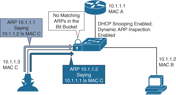
Figure 17-2 ARP Packet Validation on a VLAN Enabled for DAI
If you configure interfaces as trusted when they should be untrusted, you may open a security hole in a network. If device A is not running DAI, host C can easily poison the ARP cache of device B. If you configured the link between the devices as trusted, this condition can occur even though device B is running DAI.
DAI ensures that hosts (on untrusted interfaces) connected to a device that runs DAI do not poison the ARP caches of other hosts in the network; however, DAI does not prevent hosts in other portions of the network from poisoning the caches of the hosts that are connected to a device that runs DAI.
If some devices in a VLAN run DAI and other devices do not, the guidelines for configuring the trust state of interfaces on a device that runs DAI become the following:
• Untrusted: Interfaces that are connected to hosts or to devices that are not running DAI
• Trusted: Interfaces that are connected to devices that are running DAI
To validate the bindings of packets from devices that do not run DAI, configure ARP ACLs on the device that runs DAI. When you cannot determine the bindings, isolate at Layer 3 the devices that run DAI from devices that do not run DAI.
NX-OS DAI Configurations
The DAI feature does not require a license. Any feature not included in a license package is bundled with the Cisco NX-OS system images and is provided at no extra charge to you. DAI configuration recommendations and limitations are as follows:
Note
You must enable the DHCP feature before you can configure DAI.
• DAI is an ingress security feature; it does not perform any egress checking.
• DAI is not effective for hosts connected to devices that do not support DAI or that do not have this feature enabled. Because man-in-the-middle attacks are limited to a single Layer 2 broadcast domain, you should separate the domain with DAI from domains without DAI. This separation secures the ARP caches of hosts in the domain with DAI.
• DAI depends on the entries in the DHCP snooping binding database to verify IP-to-MAC address bindings in incoming ARP requests and ARP responses. If you want DAI to use static IP-MAC address bindings to determine if ARP packets are valid, you need to enable DHCP snooping. If you want DAI to use dynamic IP-MAC address bindings to determine if ARP packets are valid, you must configure DHCP snooping on the same VLANs on which you configure DAI.
• When you use the feature dhcp command to enable the DHCP feature, there is a delay of approximately 30 seconds before the I/O modules receive the DHCP or DAI configuration. This delay occurs regardless of the method that you use to change from a configuration with the DHCP feature disabled to a configuration with the DHCP feature enabled. For example, if you use the Rollback feature to revert to a configuration that enables the DHCP feature, the I/O modules receive the DHCP and DAI configuration approximately 30 seconds after you complete the rollback.
• When DHCP snooping is disabled or used in a non-DHCP environment, you should use ARP ACLs to permit or to deny packets and disable DAI.
• DAI is supported on access ports, trunk ports, port-channel ports, and private VLAN (PVLAN) ports.
• The DAI trust configuration of a port channel determines the trust state of all physical ports that you assign to the port channel. For example, if you have configured a physical port as a trusted interface and then you add that physical port to a port channel that is an untrusted interface, the physical port becomes untrusted.
• When you remove a physical port from a port channel, the physical port does not retain the DAI trust state configuration of the port channel.
• When you change the trust state on the port channel, the device configures a new trust state on all the physical ports that comprise the channel.
• If you want DAI to use static IP-MAC address bindings to determine if ARP packets are valid, ensure that DHCP snooping is enabled and that you have configured the static IP-MAC address bindings.
• If you want DAI to use dynamic IP-MAC address bindings to determine if ARP packets are valid, ensure that DHCP snooping is enabled.
Table 17-10 lists the default settings for DAI parameters. You can alter these parameters as necessary.
Table 17-10 Default DAI Parameters

Tables 17-11 through 17-13 show some of the most-used DAI configuration commands. For a full list of commands, refer to the Nexus Security Configuration Guide links in the “References” section at the end of this chapter.
Table 17-11 DAI Global Commands

Table 17-12 DAI Interface-Level Commands

Table 17-13 DAI Verification Commands

Figure 17-3 shows a network topology example. Host 1 is connected to switch A, and host 2 is connected to switch B. Both Nexus switches are running DAI on VLAN 1, where the hosts are located. A DHCP server is connected to switch A. Both hosts acquire their IP addresses from the same DHCP server. Switch A has the bindings for host 1 and host 2, and switch B has the binding for host 2. Switch A’s Ethernet interface E2/3 is connected to switch B’s Ethernet interface E1/4.
![]()
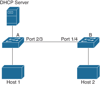
Figure 17-3 Nexus DAI Network Topology
DAI depends on the entries in the DHCP snooping binding database to verify IP-to-MAC address bindings in incoming ARP requests and ARP responses. You must make sure to enable DHCP snooping to permit ARP packets that have dynamically assigned IP addresses. This configuration does not work if the DHCP server is moved from switch A to a different location.
To ensure that this configuration does not compromise security, configure interface E2/3 on switch A and interface E1/4 on switch B as trusted.
To enable DAI and configure interface E2/3 on switch A as trusted, follow these steps:
Step 1. While logged in to switch A, verify the connection between switch A and switch B using the cdp neighbors command, as shown in Example 17-8.
Example 17-8 Switch A CDP Neighbors
switchA# show cdp neighbors
Capability Codes: R - Router, T - Trans-Bridge, B - Source-Route-Bridge
                  S - Switch, H - Host, I - IGMP, r - Repeater,
                  V - VoIP-Phone, D - Remotely-Managed-Device,
                  s - Supports-STP-Dispute
Device ID              Local Intrfce   Hldtme  Capability  Platform      Port ID
switchB                Ethernet2/3     177     R S I    WS-C2960-24TC Ethernet1/4
switchA#
Step 2. Enable DAI on VLAN 1 and verify the configuration, as shown in Example 17-9.
Example 17-9 Switch A Enabling IP ARP Inspection on VLAN 1
switchA# config t
switchA(config)# ip arp inspection vlan 1
switchA(config)# show ip arp inspection vlan 1
Source Mac Validation      : Disabled
Destination Mac Validation : Disabled
IP Address Validation      : Disabled
Vlan : 1
-----------
Configuration   : Enabled
Operation State : Active
switchA(config)#
Step 3. Configure Ethernet interface 2/3 as trusted, as shown in Example 17-10.
Example 17-10 Switch A Enabling IP ARP Trust on Interface E2/3
switchA(config)# interface ethernet 2/3
switchA(config-if)# ip arp inspection trust
switchA(config-if)# exit
switchA(config)# exit
switchA# show ip arp inspection interface ethernet 2/3
 Interface        Trust State    Rate (pps)    Burst Interval
 -------------    -----------    ----------    --------------
 Ethernet2/3      Trusted           15             5
Step 4. Verify DHCP bindings, as shown in Example 17-11.
Example 17-11 Switch A DHCP Binding
switchA# show ip dhcp snooping binding
MacAddress         IpAddress        LeaseSec  Type           VLAN  Interface
-----------------  ---------------  --------  -------------  ----  -------------
00:60:0b:00:12:89  10.0.0.1         0         dhcp-snooping  1     Ethernet2/3
switchA#
Step 5. Check the statistics before and after DAI, as shown in Example 17-12.
Example 17-12 Switch A ARP Inspection Statistics
switchA# show ip arp inspection statistics vlan 1
Vlan : 1
-----------
ARP Req Forwarded  = 0
ARP Res Forwarded  = 0
ARP Req Dropped    = 0
ARP Res Dropped    = 0
DHCP Drops         = 0
DHCP Permits       = 0
SMAC Fails-ARP Req = 0
SMAC Fails-ARP Res = 0
DMAC Fails-ARP Res = 0
IP Fails-ARP Req   = 0
IP Fails-ARP Res   = 0
switchA#
!!  If host 1 sends out two ARP requests with an IP address of 10.0.0.1 and a MAC address of 0002.0002.0002, both requests are permitted,
switchA# show ip arp inspection statistics vlan 1
Vlan : 1
-----------
ARP Req Forwarded  = 2
ARP Res Forwarded  = 0
ARP Req Dropped    = 0
ARP Res Dropped    = 0
DHCP Drops         = 0
DHCP Permits       = 2
SMAC Fails-ARP Req = 0
SMAC Fails-ARP Res = 0
DMAC Fails-ARP Res = 0
IP Fails-ARP Req   = 0
IP Fails-ARP Res   = 0
If host 1 tries to send an ARP request with an IP address of 10.0.0.3, the packet is dropped and an error message is logged, as shown in Example 17-13.
Example 17-13 Switch A DIA DHCP Logs
00:12:08: %SW_DAI-4-DHCP_SNOOPING_DENY: 2 Invalid ARPs (Req) on Ethernet2/3, vlan 1.([0002.0002.0002/10.0.0.3/0000.0000.0000/0.0.0.0/02:42:35 UTC Fri Aug 16 2019])
ARP request drop statistics can be displayed, as shown in Example 17-14.
Example 17-14 Switch A ARP Inspection Drop Statistics
switchA# show ip arp inspection statistics vlan 1
switchA#
Vlan : 1
-----------
ARP Req Forwarded  = 2
ARP Res Forwarded  = 0
ARP Req Dropped    = 2
ARP Res Dropped    = 0
DHCP Drops         = 2
DHCP Permits       = 2
SMAC Fails-ARP Req = 0
SMAC Fails-ARP Res = 0
DMAC Fails-ARP Res = 0
IP Fails-ARP Req   = 0
IP Fails-ARP Res   = 0
switchA#
To enable DAI and configure Ethernet interface 1/4 on switch B as trusted, follow these steps:
Step 1. While logged in to switch B, verify the connection between switch A and switch B, as shown in Example 17-15.
Example 17-15 Switch B CDP Neighbors
switchB# show cdp neighbors
Capability Codes: R - Router, T - Trans-Bridge, B - Source-Route-Bridge
                  S - Switch, H - Host, I - IGMP, r - Repeater,
                  V - VoIP-Phone, D - Remotely-Managed-Device,
                  s - Supports-STP-Dispute
Device ID              Local Intrfce   Hldtme  Capability  Platform      Port ID
switchA                Ethernet1/4     120     R S I    WS-C2960-24TC Ethernet2/3
switchB#
Step 2. Enable DAI on VLAN 1, and verify the configuration, as shown in Example 17-16.
Example 17-16 Switch B Enabling IP ARP Inspection on VLAN 1
switchB# config t
switchB(config)# ip arp inspection vlan 1
switchB(config)# show ip arp inspection vlan 1
Source Mac Validation      : Disabled
Destination Mac Validation : Disabled
IP Address Validation      : Disabled
Vlan : 1
-----------
Configuration   : Enabled
Operation State : Active
switchB(config)#
Step 3. Configure Ethernet interface 1/4 as trusted, as shown in Example 17-17.
Example 17-17 Switch B Enabling IP ARP Trust on Interface E1/4
switchB(config)# interface ethernet 1/4
switchB(config-if)# ip arp inspection trust
switchB(config-if)# exit
switchB(config)# exit
switchB# show ip arp inspection interface ethernet 1/4
 Interface        Trust State    Rate (pps)    Burst Interval
 -------------    -----------    ----------    --------------
 Ethernet1/4      Trusted           15             5
switchB#
Step 4. Verify the list of DHCP snooping bindings, as shown in Example 17-18.
Example 17-18 Switch B DHCP Binding
switchB# show ip dhcp snooping binding
MacAddress         IpAddress        LeaseSec  Type           VLAN  Interface
-----------------  ---------------  --------  -------------  ----  -------------
00:01:00:01:00:01  10.0.0.2         4995      dhcp-snooping  1     Ethernet1/4
switchB#
Step 5. Check the statistics before and after DAI processes, as shown in Example 17-19.
Example 17-19 Switch B ARP Inspection Statistics
switchB# show ip arp inspection statistics vlan 1
Vlan : 1
-----------
ARP Req Forwarded  = 0
ARP Res Forwarded  = 0
ARP Req Dropped    = 0
ARP Res Dropped    = 0
DHCP Drops         = 0
DHCP Permits       = 0
SMAC Fails-ARP Req = 0
SMAC Fails-ARP Res = 0
DMAC Fails-ARP Res = 0
IP Fails-ARP Req   = 0
IP Fails-ARP Res   = 0
switchB#
!! If Host 2 sends out an ARP request with the IP address 10.0.0.2 and the MAC address 0001.0001.0001, the packet is forwarded and the statistics are updated (Example 17-21).

switchB# show ip arp inspection statistics vlan 1
Vlan : 1
-----------
ARP Req Forwarded  = 1
ARP Res Forwarded  = 0
ARP Req Dropped    = 0
ARP Res Dropped    = 0
DHCP Drops         = 0
DHCP Permits       = 1
SMAC Fails-ARP Req = 0
SMAC Fails-ARP Res = 0
DMAC Fails-ARP Res = 0
IP Fails-ARP Req   = 0
IP Fails-ARP Res   = 0
switchB#
If host 2 attempts to send an ARP request with the IP address 10.0.0.1, DAI drops the request and logs the system message, as shown in Example 17-20.
Example 17-20 Switch B DIA DHCP Logs
00:18:08: %SW_DAI-4-DHCP_SNOOPING_DENY: 1 Invalid ARPs (Req) on Ethernet1/4, vlan 1.([0001.0001.0001/10.0.0.1/0000.0000.0000/0.0.0.0/01:53:21 UTC Fri Jun 13 2008])
ARP request drop statistics can be displayed, as shown in Example 17-21.
Example 17-21 Switch B ARP Inspection Drop Statistics
switchB# show ip arp inspection statistics vlan 1
Vlan : 1
-----------
ARP Req Forwarded  = 1
ARP Res Forwarded  = 0
ARP Req Dropped    = 1
ARP Res Dropped    = 0
DHCP Drops         = 1
DHCP Permits       = 1
SMAC Fails-ARP Req = 0
SMAC Fails-ARP Res = 0
DMAC Fails-ARP Res = 0
IP Fails-ARP Req   = 0
IP Fails-ARP Res   = 0
switchB#
NX-OS DHCP Snooping
DHCP snooping acts like a firewall between untrusted hosts and trusted DHCP servers. DHCP snooping performs the following activities:
• Validates DHCP messages received from untrusted sources and filters out invalid messages.
• Builds and maintains the DHCP snooping binding database, which contains information about untrusted hosts with leased IP addresses.
• Uses the DHCP snooping binding database to validate subsequent requests from untrusted hosts.
DHCP snooping can be enabled globally and on a per-VLAN basis. By default, the feature is disabled globally and on all VLANs. You can enable the feature on a single VLAN or a range of VLANs.
DHCP Snooping Trusted and Untrusted Sources
The DHCP snooping feature determines whether traffic sources are trusted or untrusted. An untrusted source may initiate traffic attacks or other hostile actions. To prevent such attacks, DHCP snooping filters messages from untrusted sources.
In an enterprise network, a trusted source is a device that is under your administrative control. These devices include the switches, routers, and servers in the network. Any device beyond the firewall or outside the network is an untrusted source. Generally, host ports are treated as untrusted sources.
In a service provider environment, any device that is not in the service provider network is an untrusted source (such as a customer switch); host ports are untrusted sources.
In the Cisco NX-OS device, you can indicate that a source is trusted by configuring the trust state of its connecting interface. The default trust state of all interfaces is untrusted. You must configure DHCP server interfaces as trusted. You can also configure other interfaces as trusted if they connect to devices (such as switches or routers) inside your network. You usually do not configure host port interfaces as trusted. Figure 17-4 shows trusted and untrusted ports.
![]()
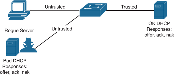
Figure 17-4 DHCP Snooping Trusted and Untrusted Ports
Note
For DHCP snooping to function properly, all DHCP servers must be connected to the device through trusted interfaces.
DHCP snooping updates the database when the device receives specific DHCP messages. For example, the feature adds an entry to the database when the device receives a DHCPACK message from the server. The feature removes the entry in the database when the IP address lease expires, or the device receives a DHCPRELEASE message from the host.
Each entry in the DHCP snooping binding database includes the MAC address of the host, the leased IP address, the lease time, the binding type, and the VLAN number and interface information associated with the host. Dynamic ARP inspection and IP Source Guard also use information stored in the DHCP snooping binding database.
You can remove entries from the binding database by using the clear ip dhcp snooping binding command.
DHCP Snooping Packet Validation
The device validates DHCP packets received on the untrusted interfaces of VLANs that have DHCP snooping enabled. The device forwards the DHCP packet unless any of the following conditions occur (in which case, the packet is dropped):
• The device receives a DHCP response packet (such as a DHCPACK, DHCPNAK, or DHCPOFFER packet) on an untrusted interface.
• The device receives a packet on an untrusted interface, and the source MAC address and the DHCP client hardware address do not match. This check is performed only if the DHCP snooping MAC address verification option is turned on.
• The device receives a DHCPRELEASE or DHCPDECLINE message from an untrusted host with an entry in the DHCP snooping binding table, and the interface information in the binding table does not match the interface on which the message was received.
In addition, you can enable strict validation of DHCP packets, which checks the options field of DHCP packets, including the “magic cookie” value in the first four bytes of the options field. By default, strict validation is disabled. When you enable it, by using the ip dhcp packet strict-validation command, if DHCP snooping processes a packet that has an invalid options field, it drops the packet.
DHCP Snooping Option 82 Data Insertion
DHCP can centrally manage the IP address assignments for a large number of subscribers. When you enable Option 82, the device identifies a subscriber device that connects to the network (in addition to its MAC address). Multiple hosts on the subscriber LAN can connect to the same port on the access device and are uniquely identified.
When you enable Option 82 on the Cisco NX-OS device, the following sequence of events occurs:
1. The host (DHCP client) generates a DHCP request and broadcasts it on the network.
2. When the Cisco NX-OS device receives the DHCP request, it adds the Option 82 information in the packet. The Option 82 information contains the device MAC address (the remote ID suboption) and the port identifier, vlan-mod-port, from which the packet is received (the circuit ID suboption). For hosts behind the port channel, the circuit ID is filled with the if_index of the port channel.
3. The device forwards the DHCP request that includes the Option 82 field to the DHCP server.
4. The DHCP server receives the packet. If the server is Option 82 capable, it can use the remote ID, the circuit ID, or both to assign IP addresses and implement policies, such as restricting the number of IP addresses that can be assigned to a single remote ID or circuit ID. The DHCP server echoes the Option 82 field in the DHCP reply.
5. The DHCP server sends the reply to the Cisco NX-OS device. The Cisco NX-OS device verifies that it originally inserted the Option 82 data by inspecting the remote ID and possibly the circuit ID fields. The Cisco NX-OS device removes the Option 82 field and forwards the packet to the interface that connects to the DHCP client that sent the DHCP request.
NX-OS DHCP Snooping Configuration
The DHCP snooping feature does not require a license. Any feature not included in a license package is bundled with the Cisco NX-OS system images and is provided at no extra charge to you. DHCP snooping configuration recommendations and limitations are as follows:
• If you are using both the Unicast Reverse Packeting Forwarding (uRFP) strict mode in your client vPC VLANs and the First Hop Redundancy Protocol (FHRP) with the DHCP relay feature, the DHCP requests are sourced from the physical egress IP address interface (not the FHRP VIP) by default. Consequently, if your DHCP server is not on a directly connected subnet and you have multiple ECMP routes back to your vPC pair, some packets might land on the neighbor switch instead of the originating switch and be dropped by RFP. This behavior is expected. To avoid this scenario, perform one of the following workarounds:
• Use the uRFP loose mode, not uRFP strict.
• Configure static routes for the interface address on the affected FHRP interfaces and redistribute the static routes into IGP.
• Using the ip dhcp relay source-interface interface-name command, you can configure a different interface as the source interface.
• After System Switchover, DHCP Global stats show incorrect values as they get erased because they are not stored in persistent storage service (PSS). The PSS component works with system services to recover states in the event of a service restart. Updating stats in PSS during packet path will affect scale.
• If you use DHCP relay where DHCP clients and servers are in different VRF instances, use only one DHCP server within a VRF.
• Before globally enabling DHCP snooping on the device, make sure that the devices acting as the DHCP server and the DHCP relay agent are configured and enabled.
• DHCP snooping does not work with DHCP relay configured on the same Nexus device.
• If a VLAN ACL (VACL) is configured on a VLAN that you are configuring with DHCP snooping, ensure that the VACL permits DHCP traffic between DHCP servers and DHCP hosts. When both DHCP snooping and DHCP relay are enabled on a VLAN and the SVI of that VLAN, DHCP relay takes precedence.
• If an ingress router ACL is configured on a Layer 3 interface that you are configuring with a DHCP server address, ensure that the router ACL permits DHCP traffic between DHCP servers and DHCP hosts.
• ACL statistics are not supported if the DHCP snooping feature is enabled.
• Before using POAP, make sure that DHCP snooping feature is enabled and firewall rules are set to block unintended or malicious DHCP servers.
• When you configure DHCPv6 server addresses on an interface, a destination interface cannot be used with global IPv6 addresses.
Table 17-14 shows the default settings for DHCP snooping parameters. You can alter these parameters as necessary.
Table 17-14 DHCP Snooping Default Parameters

Tables 17-15 through 17-17 show some of the most-used DHCP snooping configuration commands. For a full list of commands, refer to the Nexus Security Configuration Guide links in the “References” section at the end of this chapter.
Table 17-15 DHCP Snooping Global Commands

Table 17-16 DHCP Snooping Interface-Level Command

Table 17-17 DHCP Snooping Verification and Clearing Commands

Example 17-22 shows how to enable the NX-OS IP DHCP snooping feature on VLAN 125 and configure interface E1/32 as a trusted interface.
Example 17-22 NX-OS DHCP Snooping Configuration
feature dhcp-snooping
ip dhcp snooping
ip dhcp snooping vlan 215
interface ethernet 1/32
  ip dhcp snooping trust
Port Security
Port security prevents rogue network extensions via hub or wireless access points (APs) from connecting to your switch. Because it limits the number of MAC addresses to a port, port security can also be used as a mechanism to prevent users from adding extensions to the IT-created network.
For example, if a user plugs a computer or a device into a user-facing port or data port with port security defined for a single MAC address, the computer or device itself would occupy that MAC address and not allow any devices behind it to access the network, as shown in Figure 17-5. Generally, a configuration appropriate to stop MAC flooding is also appropriate to inhibit rogue access.
![]()

Figure 17-5 Port Security Limits MAC Address to Prevent Rogue Access
Port security also allows you to configure Layer 2 physical interfaces and Layer 2 port channel interfaces to allow inbound traffic from only a restricted set of MAC addresses. The MAC addresses in the restricted set are called secure MAC addresses. In addition, the device does not allow traffic from these MAC addresses on another interface within the same VLAN. The number of MAC addresses that the device can secure is configurable per interface.
Note
Unless otherwise specified, the term interface refers to physical interfaces, port channel interfaces, and vPCs; likewise, the term Layer 2 interface refers to both Layer 2 physical interfaces and Layer 2 port channel interfaces.
The process of securing a MAC address is called learning. A MAC address can be a secure MAC address on one interface only. For each interface on which you enable port security, the device can learn a limited number of MAC addresses by using the static, dynamic, or sticky methods. The way that the device stores secure MAC addresses varies depending on how the device learned the secure MAC address.
• Static method: The static learning method allows you to manually add or remove secure MAC addresses to the running configuration of an interface. If you copy the running configuration to the startup configuration, static secure MAC addresses are unaffected if the device restarts. A static secure MAC address entry remains in the configuration of an interface until one of the following events occurs:
• You explicitly remove the address from the configuration.
• You configure the interface to act as a Layer 3 interface.
Note
Adding secure addresses by using the static method is not affected by whether dynamic or sticky address learning is enabled.
• Dynamic method: By default, when you enable port security on an interface, you enable the dynamic learning method. With this method, the device secures MAC addresses as ingress traffic passes through the interface. If the address is not yet secured and the device has not reached any applicable maximum, it secures the address and allows the traffic. The device stores dynamic secure MAC addresses in memory. A dynamic secure MAC address entry remains in the configuration of an interface until one of the following events occurs:
• The device restarts.
• The interface restarts.
• The address reaches the age limit that you configured for the interface.
• You explicitly remove the address.
• You configure the interface to act as a Layer 3 interface.
• Sticky method: If you enable the sticky method, the device secures MAC addresses in the same manner as dynamic address learning, but the device stores addresses learned by this method in nonvolatile RAM (NVRAM). As a result, addresses learned by the sticky method persist through a device restart. Sticky secure MAC addresses do not appear in the running configuration of an interface. Dynamic and sticky address learning are mutually exclusive. When you enable sticky learning on an interface, the device stops dynamic learning and performs sticky learning instead. If you disable sticky learning, the device resumes dynamic learning.
A sticky secure MAC address entry remains in the configuration of an interface until one of the following events occurs:
• You explicitly remove the address.
• You configure the interface to act as a Layer 3 interface.
Nexus Port Secure MAC Address Maximum and Dynamic Address Aging
By default, an interface can have only one secure MAC address. You can configure the maximum number of MAC addresses permitted per interface or per VLAN on an interface. Maximums apply to secure MAC addresses learned by any method: dynamic, sticky, or static. The following three limits can determine how many secure MAC addresses are permitted on an interface:
• System maximum: The device has a nonconfigurable limit of 8192 secure MAC addresses. If learning a new address would violate the device maximum, the device does not permit the new address to be learned, even if the interface or VLAN maximum has not been reached.
• Interface maximum: You can configure a maximum number of 1025 secure MAC addresses for each interface protected by port security. The default interface maximum is one address. The sum of all interface maximums on a switch cannot exceed the system maximum.
• VLAN maximum: You can configure the maximum number of secure MAC addresses per VLAN for each interface protected by port security. The sum of all VLAN maximums under an interface cannot exceed the configured interface maximum. VLAN maximums are useful only for trunk ports. There are no default VLAN maximums.
The device ages MAC addresses learned by the dynamic method and drops them after the age limit is reached. You can configure the age limit on each interface. The range is from 0 to 1440 minutes, where 0 disables aging.
The method that the device uses to determine that the MAC address age is also configurable. The two methods of determining address age are as follows:
• Inactivity: The length of time after the device last received a packet from the address on the applicable interface.
• Absolute: The length of time after the device learned the address. This is the default aging method; however, the default aging time is 0 minutes, which disables aging.
Note
When the absolute aging time is configured, MAC aging occurs even when the traffic from the source MAC is flowing. However, during MAC aging and relearning, there could be a transient traffic drop.
Port Security Violations and Actions
Port security triggers security violations when one of the following events occurs:
• MAC count violation: Ingress traffic arrives at an interface from a nonsecure MAC address and learning the address would exceed the applicable maximum number of secure MAC addresses.
• Shutdown: Port security shuts down the interface that received the packet triggering the violation. The interface is error disabled. This action is the default. After you reenable the interface, it retains its port security configuration, including its secure MAC addresses.
• Restrict: Port security drops ingress traffic from any nonsecure MAC addresses.
• MAC move violation: Ingress traffic from a secure MAC address arrives at a different interface in the same VLAN as the interface on which the address is secured.
Note
If an interface is errDisabled, you can bring it up only by flapping the interface.
Nexus Port Types and Port Security
You can configure port security only on Layer 2 interfaces. Details about port security and different types of interfaces or ports are as follows:
• Access ports: You can configure port security on interfaces that you have configured as Layer 2 access ports. On an access port, port security applies only to the access VLAN. VLAN maximums are not useful for access ports.
• Trunk ports: You can configure port security on interfaces that you have configured as Layer 2 trunk ports. The device allows VLAN maximums only for VLANs associated with the trunk port.
• SPAN ports: You can configure port security on Switched Port Analyzer (SPAN) source ports but not on SPAN destination ports.
• Ethernet port channels: You can configure port security on Layer 2 Ethernet port channels in either access mode or trunk mode.
• Fabric Extender (FEX) ports: Port security is supported on GEM (Generic Expansion Module) and FEX ports.
• Private VLAN enabled ports: Port security is supported on ports that are enabled as private VLAN ports.
Note
You cannot configure port security on VXLAN interfaces.
NX-OS Port Security Configuration
The port security feature does not require a license. Any feature not included in a license package is bundled with the Cisco NX-OS system images and is provided at no extra charge to you. Port security configuration recommendations and limitations are as follows:
• Port security is supported on PVLAN ports.
• Port security does not support SPAN destination ports.
• Port security does not depend on other features.
• If any member link in a port channel is in the preprovisioned state—that is, the module is offline—the port security feature cannot be disabled on the port channel.
• Port security is not supported on vPC ports.
• Port security operates with 802.1X on Layer 2 Ethernet interfaces.
Table 17-18 lists the default settings for NX-OS port security parameters. You can alter these parameters as necessary.
Table 17-18 NX-OS Port Security Default Parameters

Tables 17-19 through 17-21 show some of the most-used NX-OS port security configuration commands. For a full list of commands, refer to the Nexus Security Configuration Guide links in the “References” section at the end of this chapter.
Table 17-19 NX-OS Port Security Global Commands

Table 17-20 NX-OS Port Security Interface-Level Commands


Table 17-21 NX-OS Port Security Verification Commands

Example 17-23 enables port security on interface E3/2 to limit the number of total MAC addresses learned to six. It allows a maximum of three MAC addresses for VLAN10 and a maximum of two MAC addresses for VLAN 20. A violation drops all packets from an insecure host.
![]()
Example 17-23 NX-OS Port Security Configuration
feature port-security
interface Ethernet 3/2
  switchport
  switchport port-security
  switchport port-security maximum 6
  switchport port-security maximum 3 vlan 10
  switchport port-security maximum 2 vlan 20
  switchport port-security violation restrict
Nexus Control Plane Policing
Nexus Series switches are deployed as data center and campus switches. A Nexus control plane CPU is the brain of the network and handles the maximum load of the network, which includes frequent bursts of control traffic, such as OSPF, OTV, ARP, LISP, BGP, and so on.
Control Plane Policing (CoPP) protects the control plane and separates it from the data plane, which ensures network stability, reachability, and packet delivery.
CoPP allows a policy map to be applied to the control plane. This policy map looks like a normal QoS policy and is applied to all traffic entering the switch from a nonmanagement port. A common attack vector for network devices is the denial-of-service (DoS) attack, where excessive traffic is directed at the device interfaces.
Cisco NX-OS devices provide CoPP to prevent DoS attacks from impacting performance. Such attacks, which can be perpetrated either inadvertently or maliciously, typically involve high rates of traffic destined to the supervisor module or CPU itself.
The supervisor module divides the traffic that it manages into three functional components or planes:
• Data plane: Handles all the data traffic. The basic functionality of a Cisco NX-OS device is to forward packets from one interface to another. The packets that are not meant for the switch itself are called the transit packets. These packets are handled by the data plane.
• Control plane: Handles all routing protocol control traffic. These protocols, such as the Border Gateway Protocol (BGP) and Open Shortest Path First (OSPF), send control packets between devices. These packets are destined to router addresses and are called control plane packets.
• Management plane: Runs the components meant for Cisco NX-OS device management purposes, such as the command-line interface (CLI) and Simple Network Management Protocol (SNMP).
The supervisor module has both the management plane and control plane and is critical to the operation of the network. Any disruption or attacks to the supervisor module result in serious network outages. For example, excessive traffic to the supervisor module could overload and slow down the performance of the entire Cisco NX-OS device. Traffic hitting the CPU on the supervisor module can come in through three paths, as shown in Figure 17-6. Only traffic sent through an Inband interface is subject to CoPP or hardware rate limit (HWRL) because it is the only traffic that reaches the supervisor via forwarding engines.
![]()
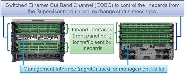
Figure 17-6 Cisco Nexus Supervisor
DoS attacks on the supervisor module could generate IP traffic streams to the control plane at a very high rate, forcing the control plane to spend a large amount of time handling these packets and preventing the control plane from processing genuine traffic. Examples of DoS attacks include
• Internet Control Message Protocol (ICMP) echo requests
• IP fragments
• TCP SYN flooding
These attacks can impact the device performance and have the following negative effects:
• Reduced service quality (such as poor voice, video, or critical applications traffic)
• High route processor or switch processor CPU utilization
• Route flaps due to loss of routing protocol updates or keepalives
• Unstable Layer 2 topology
• Slow or unresponsive interactive sessions with the CLI
• Processor resource exhaustion, such as the memory and buffers
• Indiscriminate drops of incoming packets
Note
It is important to ensure that you protect the supervisor module from accidental or malicious attacks by configuring control plane protection.
To protect the control plane, the Cisco NX-OS device segregates different packets destined for the control plane into different classes. After these classes are identified, the Cisco NX-OS device polices the packets, which ensures that the supervisor module is not overwhelmed.
Control Plane Packet
Control plane packets are the packets that are handled by the CPU. Control plane packets and some data packets punt to the CPU (or traffic destined to the CPU). These packets are as follows:
• Receive packets: Packets that have the destination address of a router. The destination address can be a Layer 2 address (such as a router MAC address) or a Layer 3 address (such as the IP address of a router interface). These packets include router updates and keepalive messages. Multicast packets can also be in this category where packets are sent to multicast addresses that are used by a router.
• Exception packets: Packets that need special handling by the supervisor module. For example, if a destination address is not present in the Forwarding Information Base (FIB) and results in a miss, the supervisor module sends an ICMP unreachable packet back to the sender. Another example is a packet with IP options set.
• Redirected packets: Packets that are redirected to the supervisor module. Features such as Dynamic Host Configuration Protocol (DHCP) snooping or dynamic Address Resolution Protocol (ARP) inspection redirect some packets to the supervisor module.
• Glean packets: If a Layer 2 MAC address for a destination IP address is not present in the FIB, the supervisor module receives the packet and sends an ARP request to the host.
All of these different packets could be maliciously used to attack the control plane and overwhelm the Cisco NX-OS device. CoPP classifies these packets to different classes and provides a mechanism to individually control the rate at which the supervisor module receives these packets.
Classification for CoPP
For effective protection, the Cisco NX-OS device classifies the packets that reach the supervisor modules to allow you to apply different rate-controlling policies based on the type of the packet. For example, you might want to be less strict with a protocol packet such as Hello messages but stricter with a packet that is sent to the supervisor module because the IP option is set.
Rate-Controlling Mechanisms
After the packets are classified, the Cisco NX-OS device has different mechanisms to control the rate at which packets arrive at the supervisor module. Two mechanisms control the rate of traffic to the supervisor module. One is called policing, and the other is called rate limiting.
Using hardware policers, you can define separate actions for traffic that conforms to, exceeds, or violates certain conditions. The actions can transmit the packet, mark down the packet, or drop the packet.
You can configure the following parameters for policing:
• Committed information rate (CIR): Desired bandwidth specified as a bit rate or a percentage of the link rate.
• Peak information rate (PIR): Desired bandwidth specified as a bit rate or a percentage of the link rate.
• Committed burst (BC): Size of a traffic burst that can exceed the CIR within a given unit of time and not impact scheduling.
• Extended burst (BE): Size that a traffic burst can reach before all traffic exceeds the PIR.
In addition, you can set separate actions such as transmit or drop for conform, exceed, and violate traffic.
When you bring up your Cisco NX-OS device for the first time, the Cisco NX-OS software installs the default copp-system-p-policy-strict policy to protect the supervisor module from DoS attacks. You can set the level of protection by choosing one of the following CoPP policy options from the initial setup utility:
• Strict: This policy is 1 rate and 2 color and has a BC value of 250 ms (except for the important class, which has a value of 1000 ms).
• Moderate: This policy is 1 rate and 2 color and has a BC value of 310 ms (except for the important class, which has a value of 1250 ms). These values are 25 percent greater than the strict policy.
• Lenient: This policy is 1 rate and 2 color and has a BC value of 375 ms (except for the important class, which has a value of 1500 ms). These values are 50 percent greater than the strict policy.
• Dense: This policy is 1 rate and 2 color. The classes critical, normal, redirect, exception, undesirable, L2-default, and default have a BC value of 250 ms. The classes important, management, normal-dhcp, normal-dhcp-relay-response, and monitoring have a BC value of 1000 ms. The class l2-unpoliced has a BC value of 5 MB.
Note
It is recommend that you use dense as a default policy when the chassis is fully loaded with F2 Series modules or loaded with more F2 Series modules than any other I/O modules.
• Skip: No control plane policy is applied.
If you do not select an option or choose not to execute the setup utility, the Cisco NX-OS software applies strict policing. We recommend that you start with the strict policy and later modify the CoPP policies as required.
The copp-system-p-policy policy has optimized values suitable for basic device operations. You must add specific class and ACL rules that meet your DoS protection requirements. The default CoPP policy does not change when you upgrade the Cisco NX-OS software.
Note
Selecting the Skip option and not subsequently configuring CoPP protection can leave your Cisco NX-OS device vulnerable to DoS attacks.
Figure 17-7 shows a Nexus 7000 CoPP strict profile example.
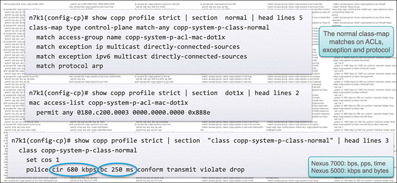
Figure 17-7 Nexus 7000 CoPP Strict Profile
Modular QoS Command-Line Interface
![]()
CoPP uses the Modular Quality of Service Command-Line Interface (MQC). MQC is a CLI structure that allows you to define a traffic class, create a traffic policy (policy map), and attach the traffic policy to an interface. The traffic policy contains the CoPP feature that will be applied to the traffic class. Steps to configure CoPP are as follows:
Step 1. Define a traffic class using the class-map command. A traffic class is used to classify traffic. Example 17-24 shows how to create a new class-map called copp-sample-class.
Example 17-24 NX-OS CoPP Class Map Configuration
class-map type control-plane copp-sample-class
Step 2. Create a traffic policy using the policy-map command. A traffic policy (policy map) contains a traffic class and one or more CoPP features that will be applied to the traffic class. The CoPP features in the traffic policy determine how to treat the classified traffic.
Step 3. Attach the traffic policy (policy map) to the control plane using the control-plane and service-policy commands. Example 17-25 shows how to attach the policy map to the control plane.
Example 17-25 NX-OS CoPP Service Policy Configuration
control-plane
service-policy input copp-system-policy
Note
The copp-system-policy is always configured and applied. You do not need to use this command explicitly.
Note
A Cisco NX-OS device supports only hardware-based CoPP that does not support the management interface (mgmt0). The out-of-band mgmt0 interface connects directly to the CPU and does not pass through the in-band traffic hardware where CoPP is implemented. On the mgmt0 interface, ACLs can be configured to give or deny access to a particular type of traffic.
Tables 17-22 through 17-24 show NX-OS class comparison for preconfigured control plane policies.
Table 17-22 Nexus 9000 CoPP Class Comparison

Table 17-23 Nexus 7000 CoPP Class Comparison

Table 17-24 Nexus 5000 CoPP Class Comparison

NX-OS CoPP Configuration
The Control Plane Policing feature does not require a license. Any feature not included in a license package is bundled with the Cisco NX-OS system images and is provided at no extra charge to you. CoPP configuration recommendations and limitations are as follows:
• CoPP classification does not work for the Layer 2 control traffic in native VLAN in the following scenarios:
• When the native vlan (ID other than 1) command is configured on the interface and the native VLAN ID is missing in the configuration.
• If the vlan dot1q tag native exclude control command is configured.
• Customizing CoPP is an ongoing process. CoPP must be configured according to the protocols and features used in your specific environment as well as the supervisor features that are required by the server environment. As these protocols and features change, CoPP must be modified.
• We recommend that you continuously monitor CoPP. If drops occur, determine if CoPP dropped traffic unintentionally or in response to a malfunction or attack. In either event, analyze the situation and evaluate the need to modify the CoPP policies.
• All the traffic that you do not specify in the other class maps is put into the last class, the default class. Monitor the drops in this class and investigate if these drops are based on traffic that you do not want or the result of a feature that was not configured and you need to add.
• All broadcast traffic is sent through CoPP logic to determine which packets (for example, ARP and DHCP) need to be redirected through an ACL to the router processor. Broadcast traffic that does not need to be redirected is matched against the CoPP logic, and both conforming and violated packets are counted in the hardware but not sent to the CPU. Broadcast traffic that needs to be sent to the CPU and broadcast traffic that does not need to be sent to the CPU must be separated into different classes.
• After you have configured CoPP, delete anything that is not being used, such as old class maps and unused routing protocols.
• You must ensure that the CoPP policy does not filter critical traffic such as routing protocols or interactive access to the device. Filtering this traffic could prevent remote access to the Cisco NX-OS device and require a console connection.
• The Cisco NX-OS software does not support egress CoPP or silent mode. CoPP is supported only on ingress (you cannot use the service-policy output copp command to the control plane interface).
• You can use the access control entry (ACE) hit counters in the hardware only for ACL logic. Use the software ACE hit counters and the show access-lists and show policy-map type control-plane commands to evaluate CPU traffic.
• The Cisco NX-OS device hardware performs CoPP on a per-forwarding-engine basis. CoPP does not support distributed policing. Therefore, you should choose rates so that the aggregate traffic does not overwhelm the supervisor module.
• If multiple flows map to the same class, individual flow statistics are not available.
Table 17-25 lists the default settings for NX-OS CoPP parameters. You can alter these parameters as necessary.
Table 17-25 NX-OS CoPP Default Parameters

Tables 17-26 through 17-29 show some of the most-used CoPP class and policy configuration commands. For a full list of commands, refer to the Nexus Security Configuration Guide links in the “References” section at the end of this chapter.
Table 17-26 NX-OS CoPP Control Plane Class Map Commands

Table 17-27 NX-OS CoPP Control Plane Policy Map Commands

Table 17-28 NX-OS CoPP Control Plane Service Map Commands

Table 17-29 NX-OS CoPP Global Command and Verification

To create a new CoPP, it is recommended that you copy an existing CoPP (strict, moderate, lenient, or dense) and modify it as shown in the following steps. (These steps apply on Nexus 9000 or Nexus 7000 Series switches only.)
Step 1. Copy one of the predefined policies, as shown in Example 17-26.
![]()
Example 17-26 Copy a Predefined NX-OS Nexus 7000 CoPP
Switch-A# copp copy profile dense prefix dccore

Switch-A# show run | begin policy
policy-map type control-plane dccore-copp-policy-dense
  class dccore-copp-class-critical
    set cos 7
    police cir 4500 kbps bc 250 ms conform transmit violate drop
  class dccore-copp-class-important
Step 2. Modify any class map or policy map, as shown in Example 17-27.
![]()
Example 17-27 Modify a CoPP by Adding a New Class
Switch-A(config)# policy-map type control-plane dccore-copp-policy-dense
Switch-A(config-pmap)# class dccore-copp-class-critical
Switch-A(config-pmap-c)# police cir 9000 kbps bc 450 ms conform transmit violate drop

Switch -A# show run | begin policy
policy-map type control-plane dccore-copp-policy-dense
  class dccore-copp-class-critical
    set cos 7
    police cir 9000 kbps bc 450 ms conform transmit violate drop
  class dccore-copp-class-important
    set cos 6
    police cir 1400 kbps bc 1500 ms conform transmit violate drop
Cisco ACI Contracts
Network and application security best practices are required to control traffic flows and permit specific traffic between two applications or devices. ACI contracts provide a way for the Cisco Application Centric Infrastructure (ACI) administrator to control traffic flow within the ACI fabric between endpoint groups (EPGs). These contracts are built using a provider-consumer model where one endpoint group provides the services it wants to offer, and another endpoint group consumes them. Contracts are assigned a scope of Global, Tenant, VRF, or Application Profile, which limit the accessibility of the contract (see Figure 17-8).

Figure 17-8 Contract Component
Contracts contain the following items:
• Subjects: A group of filters for a specific application or service.
• Filters: A technique to classify traffic based on Layer 2 to Layer 4 attributes (such as Ethernet type, protocol type, TCP flags, and ports).
• Actions: Tasks to be taken on the filtered traffic. The following actions are supported:
• Permit the traffic (regular contracts, only).
• Mark the traffic (DSCP/CoS) (regular contracts, only).
• Redirect the traffic (regular contracts, only, through a service graph).
• Copy the traffic (regular contracts, only, through a service graph or SPAN).
• Block the traffic (taboo contracts, only).
• Log the traffic (taboo contracts, only).
• Labels: (Optional) A method to group objects such as subjects and endpoint groups for the purpose of increasing granularity in policy enforcement.
In the ACI security model, contracts contain the policies that govern the communication between EPGs. The contract specifies what can be communicated, and the EPGs specify the source and destination of the communications. Contracts link EPGs, as shown here:
EPG 1 --------------- CONTRACT --------------- EPG 2
Endpoints in EPG 1 can communicate with endpoints in EPG 2 and vice versa if the contract allows it. This policy construct is very flexible. Many contracts can exist between EPG 1 and EPG 2, more than two EPGs can use a contract, and contracts can be reused across multiple sets of EPGs, and more.
There is also directionality in the relationship between EPGs and contracts. EPGs can either provide or consume a contract. An EPG that provides a contract is typically a set of endpoints that provide a service to a set of client devices. The protocols used by that service are defined in the contract. An EPG that consumes a contract is typically a set of endpoints that are clients of that service. When the client endpoint (consumer) tries to connect to a server endpoint (provider), the contract checks to see if that connection is allowed. Unless otherwise specified, that contract would not allow a server to initiate a connection to a client. However, another contract between the EPGs could easily allow a connection in that direction.
This providing/consuming relationship is typically shown graphically with arrows between the EPGs and the contract. Note the direction of the arrows shown here:
EPG 1 <-------consumes-------- CONTRACT <-------provides-------- EPG 2
The contract is constructed in a hierarchical manner. It consists of one or more subjects, each subject contains one or more filters, and each filter can define one or more protocols, as shown in Figure 17-9.
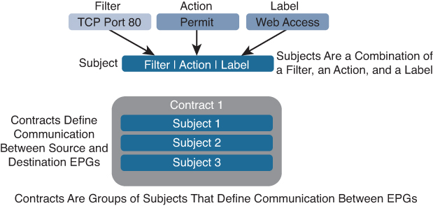
Figure 17-9 ACI Subjects and Contracts
While different endpoint groups can only communicate with other endpoint groups based on the contract rules defined, no contract is required for intra-endpoint group communication. Intra-endpoint group communication from endpoint to endpoint in the same endpoint group is allowed by default.
If a filter allows traffic from any consumer port to a provider port (such as 8080), and if reverse port filtering is enabled and the contract is applied in both directions (say for TCP traffic), either the consumer or the provider can initiate communication. The provider could open a TCP socket to the consumer using port 8080, whether the provider or consumer sent traffic first.
For more information on default permitted traffic and an example, review Chapter 4, “Describe Cisco Application Centric Infrastructure”
![]()
Cisco ACI Contract Configuration Parameters
When configuring contracts, you can define the following options:
• Application-profile: This contract can be applied to any endpoint groups in the same application profile.
• Contract scope: The scope of a service contract between two or more participating peer entities or endpoint groups. The contract is not applied to any consumer endpoint group outside the scope of the provider endpoint group.
The states are
• Private network: This contract can be applied to any endpoint groups within the same VRF. (This is the default.)
• Tenant: This contract can be applied to any endpoint groups within the same tenant.
• Global: This contract can be applied to any endpoint groups throughout the fabric.
• QoS class: You can set the priority level of the service contract. The priority level can be
• Unspecified (this is the default).
• Level1: Class 1 differentiated services code point (DSCP) value.
• Level2: Class 2 DSCP value.
• Level3: Class 3 DSCP value.
• Tags (labels): (Optional) The search keyword or term that is assigned to the application profile. A tag allows you to group multiple objects by a descriptive name. You can assign the same tag name to multiple objects, and you can assign one or more tag names to an object. When contracts are assigned to an endpoint group as either a consumer or provider, by default all subjects within a contract apply to the endpoint group. With tags, only endpoint groups in application profiles with matching criteria implement the subject of the contract.
• Match: The subject match criteria across consumer endpoint groups. Labels can be applied to a variety of provider and consumer-managed objects, including endpoint groups, contracts, bridge domains, DHCP relay policies, and DNS policies. When you are checking for a match of provider labels and consumer labels, the match setting is determined by the provider endpoint group. The different options are
• AtleastOne: At least one label matches on provider and consumer endpoint groups. Blank labels are considered a match. (This is the default.)
• AtmostOne: The setting matches only when all labels on the endpoint groups are exactly the same. Blank labels are considered a match.
• None: None of the subject labels match.
• All: The setting matches only when both endpoint groups have all labels, excluding blank labels.
Create, Modify, or Remove Regular Contracts
You can create or modify or remove tenant contracts to control traffic flow between endpoint groups. Only users with the administrator privilege can create, modify, or remove a contract.
To create a contract using the ACI GUI, follow these steps:
Step 1. On the menu bar, choose Tenants > ALL TENANTS. In the Work pane, choose Tenant_Name.
Step 2. In the Navigation pane, choose Tenant_Name > Security Policies > Contracts.
Step 3. In the Work pane, choose Actions > Create Contract.
Step 4. In the Create Contract dialog box, perform the following actions:
• Enter a Contract Name.
• Choose a Contract Scope (optional).
• Choose a QoS Class (optional).
• Click + (the plus sign) next to the Subject to add a Contract Subject.
• In the Create Contract Subject dialog box, perform the following actions:
• Enter a Contract Subject Name.
• Click + in the Filter Chain field.
Step 5. Click Update, click OK, and then click Submit.
To create a contract using the Cisco NX-OS, follow these steps:
Step 1. Get into the configuration mode using the Cisco NX-OS CLI. Then enter the following:
apic1# configure
apic1(config)#
Step 2. To create the contracts and assign an access group (filters) for HTTPS traffic between EPGs, enter the following:
apic1(config)# tenant <tenant name>
apic1(config-tenant)# contract <contract name>
apic1(config-tenant-contract)# subject <subject name>
apic1(config-tenant-contract-subj)# access-group <access group name>  both
apic1(config-tenant-contract-subj)# exit
apic1(config-tenant-contract)# exit
To modify an existing contract using the ACI GUI, follow these steps:
Step 1. On the menu bar, choose Tenants > ALL TENANTS. Then in the Work pane, choose Tenant_Name.
Step 2. In the Navigation pane, choose Tenant_Name > Security Policies > Contracts > Contract_Name.
Step 3. In the Work pane, choose the Policy tab. Then do the following:
• Choose a Contract Scope (optional).
• Choose a QoS Class (optional).
• Click + next to the Subject field to add a Contract Subject.
• In the Create Contract Subject dialog box, perform the following actions:
• Enter a Contract Subject Name.
• Click + next to Filter Chain.
Step 4. Click Update, click OK, and then click Submit.
To remove a contract using the ACI GUI, follow these steps:
Step 1. On the menu bar, choose Tenants > ALL TENANTS. In the Work pane, choose Tenant_Name.
Step 2. In the Navigation pane, choose Tenant_Name > Security Policies > Contracts > Contract_Name.
Step 3. In the Work pane, choose Actions > Delete.
To verify a contract using the ACI API or shell command, you can use these commands:
REST API: /api/node/class/vzBrCP.xml
Shell Command : admin@apic1:~> moquery -c vzBrCP
To apply a contract to an EPG using the ACI GUI, follow these steps:
Step 1. On the menu bar, choose Tenants > ALL TENANTS. In the Work pane, choose Tenant_Name.
Step 2. In the Navigation pane, choose Tenant_Name > Application Profiles > Application_Profile_Name > Application EPGs > EPG_Name > Contracts.
Step 3. In the Work pane, choose Actions > Add Provided Contract or Actions > Add Consumed Contract.
Note
Choose the action depending on how the contract is to be deployed.
In the Add Contract dialog box, perform the following actions:
• Enter a Contract_Name.
• Choose a QOS policy (optional).
• Choose a Label (optional).
Step 4. Click Submit.
Apply or Remove VRF Contracts
To apply contracts to all endpoint groups within a VRF, you can apply the contract directly to the VRF. This concept is also referred as a vzAny endpoint group. It simplified contract management by allowing the contract configuration for all endpoint groups within a VRF, also optimizing hardware resource consumption.
For example, if a Cisco ACI administrator has 100 endpoint groups that are all part of the same VRF, he can apply the contracts to this one vzAny group under the VRF rather than to each endpoint group.
Traditionally, VRF-wide contracts allow established traffic, allowing endpoint group contracts to define traffic in only one direction—from consumer to provider—without the need to have reverse port forwarding enabled for TCP traffic. Because all endpoint groups within the VRF allow established traffic, reverse port forwarding is unnecessary in the contract applied to the endpoint group directly.
A quick trick to see if contracts, or the lack thereof, are blocking traffic within the VRF in an ACI fabric is to unenforce the VRF. This technique allows communication between all endpoint groups within the VRF without the need for contracts. This is equivalent to applying the common tenant contract vzAny to the VRF endpoint group.
Note
If a very large number of contracts exists within the VRF, re-implementing the contracts in the leaf switches can take up to an hour or more when the VRF is moved back to enforced.
To apply a contract to a VRF (vzAny) using the GUI, follow these steps:
Step 1. On the menu bar, choose Tenants > ALL TENANTS. In the Work pane, choose Tenant_Name.
Step 2. In the Navigation pane, choose Tenant_Name > Networking > Private Networks > Private_Network_Name > EPG Collection for Context.
Step 3. In the Work pane, click + next to either Add Provided Contract or Add Consumed Contract.
Note
Make a selection depending on how the contract is to be deployed.
Then do the following:
• Enter a Contract_Name.
• Choose a QOS Type.
• Choose Match Criteria.
Step 4. Click Update.
To verify a contract using the ACI API or shell command, you can use these commands:
REST API: /api/node/class/vzBrCP.xml
Shell Command : admin@apic1:~> moquery -c vzBrCP
Inter-Tenant Contracts
Some services, such as DNS for name resolution and Active Directory for user management, are common or shared across tenants. Because these services are shared, you need to allow their traffic across the whole fabric. Communication between EPGs that belong to different tenants is allowed only when they share the same contract. To use the same contract, you need to export the source tenant to the appropriate destination tenant. That contract appears under the Imported Contract section in the Security Policies of the destination tenant.
A consumed contract interface is used to associate an EPG from the destination tenant with the imported contract.
Note
A consumed contract interface represents one or more subjects defined under the contract. By associating to an interface, an endpoint group starts consuming all the subjects represented by the interface.
In the following example, EPG-1 in tenant Cisco-1 requires communication with EPG-2 in tenant Cisco-2. This is accomplished by utilizing contact interfaces. As illustrated in Figure 17-10, the tenant Cisco-1 user exports the intended contract interfaces and selects a provider to provide the contrast to EPG-2. The user then confirms the imported contract in tenant Cisco-2 and selects the contract as consumed. To advertise the routes from the source VRF to the intended VRF, the user must create the subnet within the EPG.
![]()

Figure 17-10 Exporting Contracts Between Tenants
To export the contract from Cisco-1/EPG-1 to Cisco-2/EPG-2, follow these steps:
Step 1. From tenant Cisco-1/EPG-1, do the following:
• Create an export contract under Security Policies.
• Create the host subnet (default Gateway IP) under EPG1 - subnet scope shared.
• Add the contract under EPG1 - contract type provider.
• Create the host subnet under the bridge domain - subnet scope private/public.
Step 2. From tenant Cisco-2/EPG-2, do the following:
• Confirm the exported contract is listed under Imported Contracts.
• Create the host subnet (default Gateway IP) under EPG2 - subnet scope shared.
• Add the interface contract under EPG2 - contract type consumed.
• Create the host subnet (default Gateway IP) under the bridge domain - subnet scope private/public.
Inter-Private Network Contracts Communication
In the following example, EPG-1 in VRF Cisco-1 requires communication with EPG-2 in VRF Cisco-2. This is accomplished by utilizing the subnet field within the EPG, as shown in Figure 17-11. When you create the subnet under the EPG and select shared, the route is leaked to the VRF noted within the Tenant scoped contract.
![]()

Figure 17-11 Exporting Contracts Between Private Networks
To create a subnet and share it, use the following steps:
Step 1. Create the contract under Security Policies - contract scope Tenant.
Step 2. (Tenant Cisco-1/EPG-1) Create the host subnet (default Gateway IP) under EPG1 - subnet scope shared.
Step 3. Add the contract under EPG1 - contract type provider.
Step 4. (Tenant Cisco-1/EPG-2) Create the host subnet (default Gateway IP) under EPG2 - subnet scope shared.
Step 5. Add the contract under EPG2 - contract type provider.
Single Contract Bidirectional Reverse Filter
A single contract bidirectional reverse filter is useful when implementing a contract with the option to apply the contract subject in both directions and with the option to apply the reverse filter. This is the most common because it allows a single subject/filter to be implemented with a single provider/consumer relationship.
In this example, EPG-1 provides a contract with a subject of www, and EPG-2 consumes the contract, as shown in Figure 17-12. This allows the web client in EPG-2 to access the web server in EPG-1. That is, EPG-1 provides a service to EPG-2. The web server in EPG-1 does not have access to port 80 of the web client in EPG-2. This results in a single contract with (1) subject and (1) filter (www) with a single provider and a single consumer.

Figure 17-12 Default Bidirectional Contract with Reverse Filter
Single Contract Unidirectional with Multiple Filters
This example involves implementing a contract without the option to apply the contract subject in both directions. When selecting this option, the user no longer has the option to select the reverse filter option.
In this example, EPG-1 provides a contract with a subject of icmp, and EPG-2 consumes the contract, as shown in Figure 17-13. This allows the host in EPG-1 to access the host in EPG-2 via icmp. When utilizing a single subject without the use of “Apply Both Directions,” the user must then configure two filters, one in each direction. This results in a single contract with (1) subject, (2) filters (icmp), and a single provider and a single consumer.

Figure 17-13 Single Contract, Single Unidirectional Subject, Multiple Filters
Multiple Contracts Unidirectional Single Filter
For high granularity, contracts can be implemented unidirectionally, as shown a Figure 17-14. In this example, EPG-1 provides a contract with an icmp subject, and EPG-2 consumes the contract. This allows Client 2 in EPG-2 to access the host in EPG-1 via icmp. That is, EPG-1 provides a service to EPG-2. The result is two contracts with (1) subject and (1) filter. Each contract has a single provider and a single consumer referencing the same contract. The difference here is that the contract is explicitly applied in both directions.

Figure 17-14 Multiple Contracts, Unidirectional Subjects, Single Filters
ACI Microsegmentation
Microsegmentation is a security requirement to reduce attack surfaces by minimizing the possibilities for lateral movement in the event of a security breach. With traditional networking technologies, this is very hard to accomplish. Network flow and categorized devices depend on functionality or criticality and segment them into zones, but ACI enables a new approach, by allowing degrees of flexibility and automation not possible with traditional network management and operations, making microsegmentation a distinct possibility .
Cisco ACI microsegmentation (uSeg) enables you to automatically assign endpoints to logical security zones called endpoint groups. These EPGs are based on various network-based or virtual machine–based attributes.
Microsegmentation with Cisco ACI supports virtual endpoints attached to the following:
• Cisco ACI Virtual Edge
• Cisco Application Virtual Switch (AVS)
• Microsoft vSwitch
• VMware vSphere Distributed Switch (VDS)
Microsegmentation with network-based attributes also supports bare-metal environments.
Note
You can configure microsegmentation with Cisco ACI for physical and virtual endpoints, and you can share the same EPGs for both physical and virtual endpoints.
Microsegmentation using the Cisco ACI involves the Cisco APIC, vCenter, or Microsoft System Center Virtual Machine Manager (SCVMM), and leaf switches. The workflow for microsegmentation using the Cisco ACI Virtual Edge, Cisco AVS, VMware VDS, or Microsoft vSwitch is shown here.
The APIC workflow is as follows:
1. The user configures a VMM domain for the Cisco ACI Virtual Edge, Cisco AVS, VMware VDS, or Microsoft vSwitch in the Cisco APIC.
2. The Cisco APIC connects to vCenter or SCVMM and does the following:
• Creates an instance of the Cisco ACI Virtual Edge, Cisco AVS, VMware VDS, or Microsoft vSwitch.
• Pulls VM and hypervisor inventory information from the associated VMware vCenter or Microsoft SCVMM.
3. The user creates an application EPG and associates it with a vCenter/SCVMM domain. In each vCenter/SCVMM domain, a new encapsulation is allocated for this application EPG. The application EPG does not have any attributes. The vCenter/SCVMM administrator assigns virtual endpoints to this application EPG—not to any microsegment EPGs. It is the application EPG that appears in vCenter/SCVMM as a port group.
4. The user creates a uSeg EPG and associates it with the VMM domain. The uSeg EPG does not appear in vCenter/SCVMM as a port group; it has a special function:
• The uSeg EPG has VM-based attributes to match filter criteria. If a match occurs between the uSeg EPG VM attributes and VMs, the Cisco APIC dynamically assigns the VMs to the uSeg EPG.
• The endpoints are transferred from the application EPG to the uSeg EPG. If the uSeg EPG is deleted, the endpoints are assigned back to the application EPG.
• The uSeg EPG must be assigned to a VMM domain in order for it to take effect. When you associate the uSeg EPG to a VMM domain, its criteria are applied for that VMM domain only. If you have VMware VDS, you also must assign the uSeg EPG to the same bridge domain as the application EPG.
In the case of VMware VDS, its criteria are applied for that VMM domain and bridge domain.
The leaf switch and the Cisco ACI Virtual Edge, Cisco AVS, or Microsoft vSwitch workflow is as follows:
1. The physical leaf switch pulls the attribute policies from the Cisco APIC.
2. The Cisco ACI Virtual Edge, Cisco AVS, or Microsoft vSwitch sends a VM attach message to the physical leaf switch using the OpFlex protocol when a VM attaches to the Cisco ACI Virtual Edge, Cisco AVS, or Microsoft vSwitch.
3. The physical leaf switch matches the VM against the configured attribute policies for the tenant.
4. If the VM matches the configured VM attributes, the physical leaf switch pushes the uSeg EPG—along with the corresponding encapsulation—to the Cisco ACI Virtual Edge, Cisco AVS, or Microsoft vSwitch.
Note that this action does not change the original port-group assignment for the VM in vCenter/SCVMM.
Packet forwarding for the Cisco ACI Virtual Edge, Cisco AVS, or Microsoft vSwitch workflow is as follows:
1. When the VM sends the data packets, the Cisco ACI Virtual Edge, Cisco AVS, or Microsoft vSwitch tags the packets using encapsulation corresponding to the uSeg EPG, not the application EPG.
2. The physical leaf hardware sees an attribute-based encapsulated VM packet and matches it with the configured policy.
The VM is dynamically assigned to a uSeg EPG, and the packet is forwarded based on the policy defined for that particular uSeg EPG.
![]()
Example: ACI Microsegmentation Within EPG Location
The following example covers ACI microsegmentation that segments host (VM) communications based on EPG location (groups), and the example described in the next section covers ACI microsegmentation that segments host (VM) communications based on EPG function (application).
For this example, let’s assume that you need to deploy a virtual desktop infrastructure (VDI) for the Human Resources, Finance, and Operations departments. The VDI virtual desktop VMs are part of a single application EPG called EPG_VDI with identical access requirements to the rest of the application EPGs.
Service contracts are built in such a way that the EPG-VDI has access to Internet resources and internal resources. But at the same time, the company must ensure that each of the VM groups—Human Resources, Finance, and Operations—cannot access the others even though they belong to the same application EPG, EPG_VDI.
To meet this requirement, you can create filters in the Cisco APIC that would check the names of the VMs in the application EPG, EPG_VDI. If you create a filter with the value “HR_VM,” the Cisco APIC creates a uSeg EPG—a microsegment—for all Human Resource VMs. The Cisco APIC looks for matching values in all the EPGs in a tenant even though you want to group the matching VMs within one EPG. So, when you create VMs, we recommend that you choose names unique within the tenant.
Similarly, you can create filters with the keyword “FIN_VMs” for Finance virtual desktops and “OPS_VMs” for Operations virtual desktops. These uSeg EPGs are represented as new EPGs within the Cisco APIC policy model. You can then apply contracts and filters to control access between the VM groups even though they belong to the same application EPG.
As shown in Figure 17-15, all the virtual desktop VMs from the Human Resources, Finance, and Operations groups have been moved from the application EPG, EPG_VDI, to new uSeg EPGs: EPG_OPS_MS, EP_FIN_MS, and EPG_HR_MS. Each uSeg EPG has the attribute type VM Name with a value to match key parts of the VM’s name. EPG_OPS_MS has the value OPS_VM, so all VMs in the tenant containing OPS_VM in their names become part of EPG_OPS_MS. The other uSeg EPGs have corresponding values, resulting in the movement of VMs in the tenant with matching names to the uSeg EPGs.
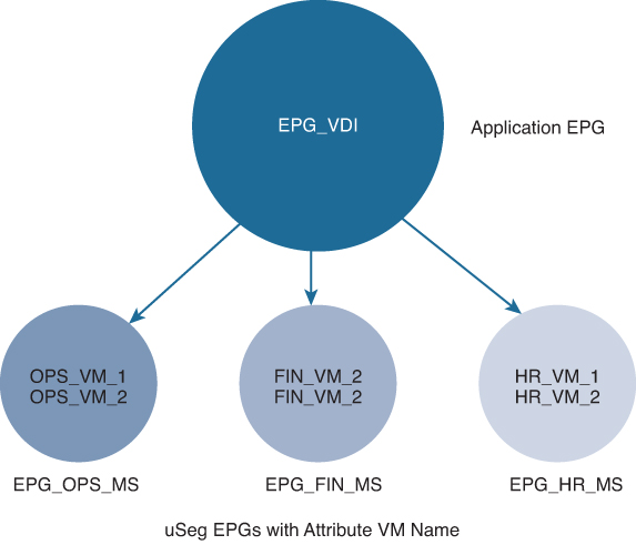
Figure 17-15 Microsegmentation with Cisco ACI with VMs from a Single Application EPG
Using microsegmentation with Cisco ACI and VMs in different application EPGs, you can configure microsegmentation with the Cisco ACI to put VMs that belong to different application EPGs into a new uSeg EPG. You might want to do this to apply policy to VMs that share a certain characteristic although they belong to different application EPGs.
![]()
Example: ACI Microsegmentation Within EPG Function
For this next example, let’s assume that you need to deploy a three-tier web application. The application is built on VMs that run different operating systems and different versions of the same operating system. For example, the VMs might run Linux, Windows 2012 R2, and Windows 2016. The application is distributed, so the company has divided the VMs into three different EPGs: EPG_Web, EPG_App, and EPG_DB.
Because of a recent vulnerability in the Windows 2012 R2 operating system, your company’s security team decided to quarantine VMs running Windows 2012 R2 in case those VMs are compromised. The security team also decided to upgrade all Windows 2012 R2 VMs to Windows 2016. It also wants to microsegment all production VMs across all EPGs and restrict external connectivity to those VMs.
To meet this requirement, you can configure a uSeg EPG in the Cisco APIC. The attribute would be Operating System, and the value of the attribute would be Windows 2012 R2.
You can now quarantine the VMs running Windows 2012 R2 and upgrade them to Windows 2016. When the upgrade is complete, the VMs will no longer be part of the uSeg EPG you created for VMs running Windows 2012 R2. This change is reflected dynamically to the Cisco APIC, and those virtual machines revert to their original EPGs.
As shown in Figure 17-16, the new uSeg EPG EPG_Windows has the attribute type Operating System and the value Windows. The VMs App_VM_2, DB_VM_1, DB_VM_2, and Web_VM_2 run Windows as their operating system—and so have been moved to the new uSeg EPG EPG_Windows. However, the VMs App_VM_1, DB_VM_3, and Web_VM_1 run Linux and so remain in their application EPGs.

Figure 17-16 Microsegmentation with Cisco ACI in Different Application EPGs
You can use the Cisco ACI to configure microsegmentation with the Cisco APIC to put VMs that belong to different application EPGs or the same EPG into a new uSeg EPG. The task is essentially the same for the Cisco ACI Virtual Edge, Cisco AVS, VMware VDS, and Microsoft vSwitch; the slight differences are noted in the procedure.
To configure new microsegmentation using the ACI GUI, use the following steps:
Step 1. Log in to the Cisco ACI.
Step 2. Choose Tenants and then choose the tenant where you want to create a microsegment.
Step 3. In the Navigation pane for the tenant, expand the Tenant folder, the Application Profiles folder, and the Profile folder.
Step 4. Complete one of the following actions:
If you are using VMware VDS, complete the following substeps; if you are using the Cisco ACI Virtual Edge, Cisco AVS, or Microsoft vSwitch, skip the following substeps and continue with step 5.
• Expand the Application EPGs folder and the folder for the application EPG.
• Right-click on the Domains (VMs and Bare-Metals) folder.
• In the Add VMM Domain Association dialog box, select the Allow Micro-Segmentation check box.
• If you are using VMware VDS, you also need to configure all the required parameters.
• Click Submit.
Step 5. In the Navigation pane for the tenant, right-click the uSeg EPGs folder, and then choose Create Useg EPG.
Step 6. In the Create USeg EPG Step 1 > Identity dialog, complete the following steps to begin creating a uSeg EPG for a group of VMs:
• In the Name field, enter a name. We recommend that you choose a name indicating that the new uSeg EPG is a microsegment.
• In the intra-EPG isolation field, select Enforced or Unenforced. If you select Enforced, the Cisco ACI prevents all communication between the endpoint devices within this uSeg EPG.
• In the Bridge Domain area, choose a bridge domain from the drop-down list.
Note
For VMware VDS, you must choose the same bridge domain that is used for the application EPG. Otherwise, the VDS uSeg will not match VM attributes and will not place the VM into a uSeg EPG.
• (Optional) In the EPG Match Precedence field, choose an integer to set the precedence for the uSeg EPG among other VM-based attribute uSeg EPGs, overriding default rules. The larger the integer, the higher the precedence.
• Click Next.
Step 7. In the Create USeg EPG Step 2 > Domains dialog, complete the following steps to associate the uSeg EPG with a VMM domain:
• Click the + (plus) icon at the right of the dialog box.
• From the Domain Profile drop-down list, choose a profile.
If you have a Cisco ACI Virtual Edge, Cisco AVS, or a VMware VDS, choose a VMware domain; if you have a Microsoft vSwitch, choose a Microsoft domain.
Note
You must choose the same domain that is used by the application EPG.
• From the Deploy Immediacy drop-down list, accept the default On Demand if you have the Cisco ACI Virtual Edge, Cisco AVS, or Microsoft vSwitch; choose Immediate if you have VMware VDS.
• From the Resolution Immediacy drop-down list, accept the default Immediate.
• In the Encap Mode drop-down list, accept the default Auto.
• In the Port Encap (or Secondary VLAN for Micro-Seg) field, accept the default value.
• If you have Cisco ACI Virtual Edge, from the Switching Mode drop-down list, choose a mode.
• Choose AVE to switch the uSeg EPG through Cisco ACI Virtual Edge; choose Native to switch the uSeg EPG through the VMware VDS.
• Click Update, and then click Finish.
Step 8. In the Navigation page for the tenant, open the folder for the uSeg EPG that you just created.
Step 9. Click the uSeg Attributes folder.
The uSeg Attributes work pane appears, where you configure attributes to filter for VMs that you want to put into the uSeg EPG.
Step 10. (Optional) If you will filter using VM-based attributes, in the uSeg Attributes work pane, from the match drop-down list, choose Match Any or Match All. The Match feature enables you to use multiple attributes to filter VMs for the uSeg EPG. The default is Match Any. The Match All feature is supported for VM-based attributes only.
Step 11. Click the + or the +( icon to add a filtering statement. The + icon allows you to create a simple statement, one that creates a filter for a single attribute. You can add multiple simple statements to filter for multiple attributes. The +( icon allows you to create a block, or nested, statement, which allows you to set attributes in a hierarchy, which filters for the highest-level attribute first and then filters for lower-level attributes.
Step 12. Complete one of the following series of steps to configure the filter.
You can configure an IP-based attribute:
• From the Select a Type… drop-down list, choose IP.
• From the Use EPG Subnet? drop-down list, choose Yes or No.
If you choose Yes, you will use a previously defined subnet as the IP attribute filter.
If you choose No, enter the VM IP address or a subnet with the appropriate subnet mask in the field to the right of the Use EPG Subnet? drop-down list.
• (Optional) Create a second IP Address filter by repeating the preceding substeps. You might want to do this to include discontinuous IP addresses in the microsegment.
• Click Submit.
Or a MAC-based attribute:
• From the Select a Type… drop-down list, choose MAC.
• In the right field, enter the MAC address of the VM.
• Click Submit.
Or a VM-based custom attribute:
• From the Select a Type… drop-down list, choose VM - Custom Attribute.
• Click the search icon next to the field to the right of the Select a Type… drop-down list.
• In the Select Custom Attribute dialog box, choose a controller from the Controller drop-down list.
• From the VM drop-down list, choose a VM.
• From the Attribute Name drop-down list, choose the name, and then click SELECT.
• From the Operator drop-down list, choose an operator, and then enter a value in the field to the right of the drop-down list.
• Click Submit.
Or a VM-based tag attribute (Cisco ACI Virtual Edge, Cisco AVS, and VMware VDS only):
• From the Select a Type… drop-down list, choose VM - Tag.
• Click the magnifying glass icon next to the Category field, and in the Select VM Category dialog box, choose the category from the Category Name drop-down list, and then click SELECT. The category that you enter must be identical to the one assigned earlier for the tag in VMware vCenter.
• From the Operator drop-down list, choose the appropriate operator.
• Click the magnifying glass icon next to the field on the right, and in the Select VM Tag dialog box, select a tag from the Tag Name drop-down list and then click SELECT.
• Click Submit.
Or any another VM-based attribute:
• From the Select a Type… drop-down list, choose a VM attribute.
• From the Operator drop-down list, choose the appropriate operator.
• Complete one of the following steps:
• If you chose the Datacenter VM-based attribute, enter the name of the data center in the field to the right of the Operator drop-down list.
• If you chose any other VM-based attribute, click the search icon next to the field to the right of the operator drop-down list, choose appropriate values for the attribute in the Select dialog box, and then click SELECT.
• Click Submit.
Step 13. Click the + or the +( icon to add additional attributes for the uSeg EPG.
Step 14. Repeat step 2 through step 13 to create additional uSeg EPGs.
Exam Preparation Tasks
As mentioned in the section “How to Use This Book” in the Introduction, you have a couple of choices for exam preparation: the exercises here, Chapter 20, “Final Preparation,” and the exam simulation questions in the Pearson Test Prep software online.
Review All Key Topics
Review the most important topics in the chapter, noted with the key topic icon in the outer margin of the page. Table 17-30 lists a reference to these key topics and the page numbers on which each is found.
![]()
Table 17-30 Key Topics for Chapter 17

Define Key Terms
Define the following key terms from this chapter, and check your answers in the Glossary.
Zero Trust (ZT)
authentication
authorization
and accounting (AAA)
Remote Authentication Dial-In User Service (RADIUS)
Terminal Access Controller Access Control System (TACACS+)
Lightweight Directory Access Protocol (LDAP)
Secure Shell (SSH)
Extensible Authentication Protocol over User Datagram Protocol (EAPoUDP)
Network Admission Control (NAC)
Microsoft Challenge-Handshake Authentication Protocol (MSCHAP)
role-based access control (RBAC)
Duplicate Address Detection (DAD)
committed information rate (CIR)
peak information rate (PIR)
differentiated services code point (DSCP)
software-defined networking (SDN)
virtual machine (VM)
References
Cisco Nexus 9000 Series NX-OS Security Configuration Guide, Release 9.2(x): https://www.cisco.com/c/en/us/support/switches/nexus-9000-series-switches/products-installation-and-configuration-guides-list.html
Cisco Nexus 7000 Series NX-OS Security Configuration Guide: https://www.cisco.com/c/en/us/td/docs/switches/datacenter/nexus7000/sw/security/config/cisco_nexus7000_security_config_guide_8x.html
The Comprehensive Guide to Securing NX-OS Devices: https://www.ciscolive.com/c/dam/r/ciscolive/emea/docs/2016/pdf/BRKDCT-3102.pdf
Cisco Application Centric Infrastructure Best Practices Guide: https://www.cisco.com/c/en/us/td/docs/switches/datacenter/aci/apic/sw/1-x/ACI_Best_Practices/b_ACI_Best_Practices/b_ACI_Best_Practices_chapter_010.html
Cisco ACI Virtualization Guide, Release 3.1(1) and 3.1(2): https://www.cisco.com/c/en/us/td/docs/switches/datacenter/aci/apic/sw/3-x/virtualization/b_ACI_Virtualization_Guide_3_1_1/b_ACI_Virtualization_Guide_3_1_1_chapter_0100.html