Chapter 11. Hazards Identification
Hazards are everywhere. Unfortunately, a hazard is not always identified until an accident occurs. It is essential to identify the hazards and reduce the risk well in advance of an accident.
For each process in a chemical plant the following questions must be asked:
The first question represents hazard identification. The last three questions are associated with risk assessment, considered in detail in Chapter 12. Risk assessment includes a determination of the events that can produce an accident, the probability of those events, and the consequences. The consequences could include human injury or loss of life, damage to the environment, or loss of production and capital equipment. Question 2 is frequently called scenario identification.
The terminology used varies considerably. Hazard identification and risk assessment are sometimes combined into a general category called hazard evaluation. Risk assessment is sometimes called hazard analysis. A risk assessment procedure that determines probabilities is frequently called probabilistic risk assessment (PRA), whereas a procedure that determines probability and consequences is called quantitative risk analysis (QRA).
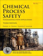
Figure 11-1 illustrates the normal procedure for using hazards identification and risk assessment. After a description of the process is available, the hazards are identified. The various scenarios by which an accident can occur are then determined. This is followed by a concurrent study of both the probability and the consequences of an accident. This information is assembled into a final risk assessment. If the risk is acceptable, then the study is complete and the process is operated. If the risk is unacceptable, then the system must be modified and the procedure is restarted.
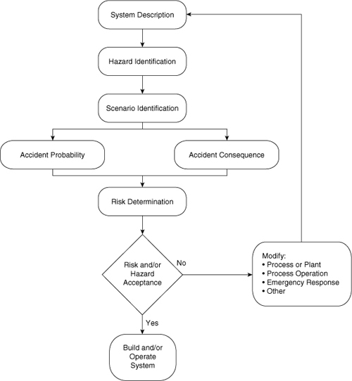
Figure 11-1. Hazards identification and risk assessment procedure. Adapted from Guidelines for Hazards Evaluation Procedures (New York: American Institute of Chemical Engineers, 1985), pp. 1–9.
The procedure described by Figure 11-1 is frequently abbreviated based on circumstances. If failure rate data on the applicable equipment are not available, then risk assessment procedures cannot be fully applied. Most plant sites (and even subunits within a plant) modify the procedure to fit their particular situation.
Hazards identification and risk assessment studies can be performed at any stage during the initial design or ongoing operation of a process. If the study is performed with the initial design, it should be done as soon as possible. This enables modifications to be easily incorporated into the final design.
Hazard identification can be performed independent of risk assessment. However, the best result is obtained if they are done together. One outcome is that hazards of low probability and minimal consequences are identified and addressed with the result that the process is “gold-plated.” This means that potentially unnecessary and expensive safety equipment and procedures are implemented. For instance, flying aircraft and tornadoes are hazards to a chemical plant. What are the chances of their occurrence, and what should be done about them? For most facilities the probability of these hazards is small: No steps are required for prevention. Likewise, hazards with reasonable probability but minimal consequences are sometimes also neglected.
An important part of the hazard identification procedure shown in Figure 11-1 is the risk acceptance step. Each organization using these procedures must have suitable criteria.
Many methods are available for performing hazard identification and risk assessment.1 Only a few of the more popular approaches are considered here. No single approach is necessarily best suited for any particular application. The selection of the best method requires experience. Most companies use these methods or adaptations to suit their particular operation.
The hazard identification methods described in this chapter include the following:
1. Process hazards checklists: This is a list of items and possible problems in the process that must be checked.
2. Hazards surveys: This can be as simple as an inventory of hazardous materials, or it can be as detailed as the Dow indexes. The Dow indexes are a formal rating system, much like an income tax form, that provides penalties for hazards and credits for safety equipment and procedures.
3. Hazards and operability (HAZOP) studies: This approach allows the mind to go free in a controlled environment. Various events are suggested for a specific piece of equipment with the participants determining whether and how the event could occur and whether the event creates any form of risk.
4. Safety review: An effective but less formal type of HAZOP study. The results are highly dependent on the experience and synergism of the group reviewing the process.
11-1. Process Hazards Checklists
A process hazards checklist is simply a list of possible problems and areas to be checked. The list reminds the reviewer or operator of the potential problem areas. A checklist can be used during the design of a process to identify design hazards, or it can be used before process operation.
A classic example is an automobile checklist that one might review before driving away on a vacation. This checklist might contain the following items:
• Check oil in engine
• Check air pressure in tires
• Check fluid level in radiator
• Check air filter
• Check fluid level in windshield washer tank
• Check headlights and taillights
• Check exhaust system for leaks
• Check fluid levels in brake system
• Check gasoline level in tank
Checklists for chemical processes can be detailed, involving hundreds or even thousands of items. But, as illustrated in the vacation example, the effort expended in developing and using checklists can yield significant results.
A typical process design safety checklist is shown in Figure 11-2. Note that three checkoff columns are provided. The first column is used to indicate those areas that have been thoroughly investigated. The second column is used for those items that do not apply to the particular process. The last column is used to mark those areas requiring further investigation. Extensive notes on individual areas are kept separate from the checklist.
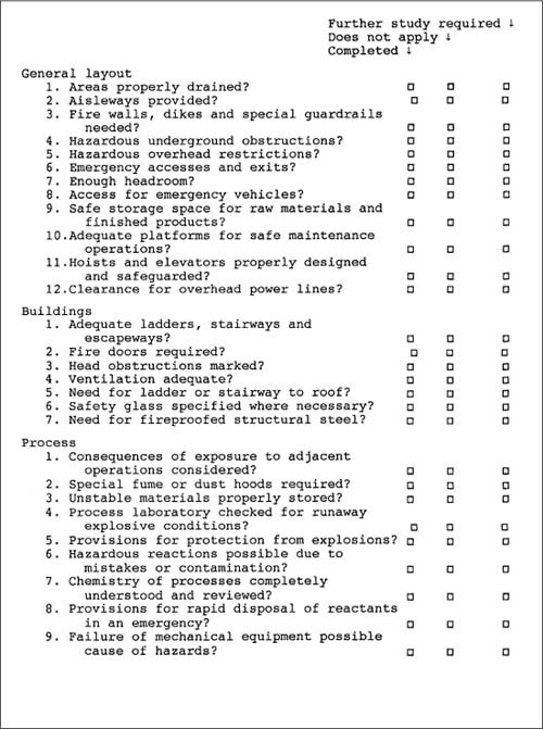


Figure 11-2. A typical process safety checklist. A list of this type is frequently used before a more complete analysis. Adapted from Henry E. Webb, “What to Do When Disaster Strikes,” in Safe and Efficient Plant Operation and Maintenance, Richard Greene, ed. (New York: McGraw-Hill, 1980).
The design of the checklist depends on the intent. A checklist intended for use during the initial design of the process will be considerably different from a checklist used for a process change. Some companies have checklists for specific pieces of equipment, such as a heat exchanger or a distillation column.
Checklists should be applied only during the preliminary stages of hazard identification and should not be used as a replacement for a more complete hazard identification procedure. Checklists are most effective in identifying hazards arising from process design, plant layout, storage of chemicals, electrical systems, and so forth.
11-2. Hazards Surveys
A hazards survey can be as simple as an inventory of hazardous materials in a facility or as complicated as a rigorous procedure such as the Dow Fire and Explosion Index (F&EI)2 and the Dow-Chemical Exposure Index (CEI)3, which are two popular forms of hazards survey. These are formal systematized approaches using a rating form, similar to an income tax form. The final rating number provides a relative ranking of the hazard. The F&EI also contains a mechanism for estimating the dollar loss in the event of an accident.
The Dow F&EI is designed for rating the relative hazards with the storage, handling, and processing of explosive and flammable materials. The main idea of this procedure is to provide a purely systematic approach, mostly independent of judgmental factors, for determining the relative magnitude of flammable hazards in a chemical plant. The main forms used for the computations are shown in Figures 11-3 and 11-4.
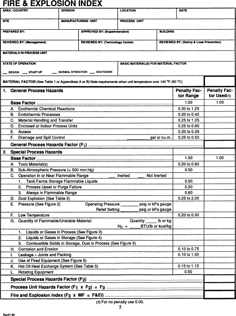
Figure 11-3. Form used in the Dow Fire and Explosion Index. The figures and tables referenced in the form are provided in the index booklet. Source: Dow’s Fire and Explosion Index Hazard Classification Guide, 7th ed. (1994). Reproduced by permission of the American Institute of Chemical Engineers.
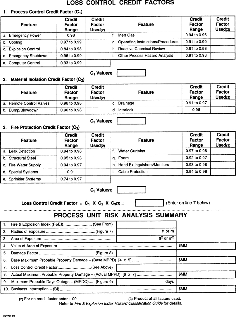
Figure 11-4. Form used for consequences analysis. Source: Dow’s Fire and Explosion Index Hazard Classification Guide, 7th ed. (1994). Reproduced by permission of the American Institute of Chemical Engineers.
The procedure begins with a material factor that is a function only of the type of chemical or chemicals used. This factor is adjusted for general and special process hazards. These adjustments or penalties are based on conditions such as storage above the flash or boiling point, endo- or exothermic reactions, and fired heaters. Credits for various safety systems and procedures are used for estimating the consequences of the hazard, after the fire and explosion index has been determined.
The form shown in Figure 11-3 consists of three columns of numbers. The first column is the penalty column. Penalties for various unsafe situations are placed in this column. The second column contains the penalty actually used. This allows for a reduction or increase in the penalty based on extenuating circumstances not completely covered by the form. In the event of uncertainty here, the complete penalty value from the first column is used. The final column is used for computation.
The first step in the procedure is to conceptually divide the process into separate process units. A process unit is a single pump, a reactor, or a storage tank. A large process results in hundreds of individual units. It is not practical to apply the fire and explosion index to all these units. The usual approach is to select only the units that experience shows to have the highest likelihood of a hazard. A process safety checklist or hazards survey is frequently used to select the most hazardous units for further analysis.
The next step is to determine the material factor (MF) for use in the form shown in Figure 11-3. Table 11-1 lists MFs for a number of important compounds. This list also includes data on heat of combustion and flash and boiling point temperatures. The additional data are also used in the computation of the Dow F&EI. A procedure is provided in the complete index for computing the material factor for other compounds not listed in Table 11-1 or provided in the Dow reference.
Table 11-1. Selected Data for the Dow Fire and Explosion Indexa
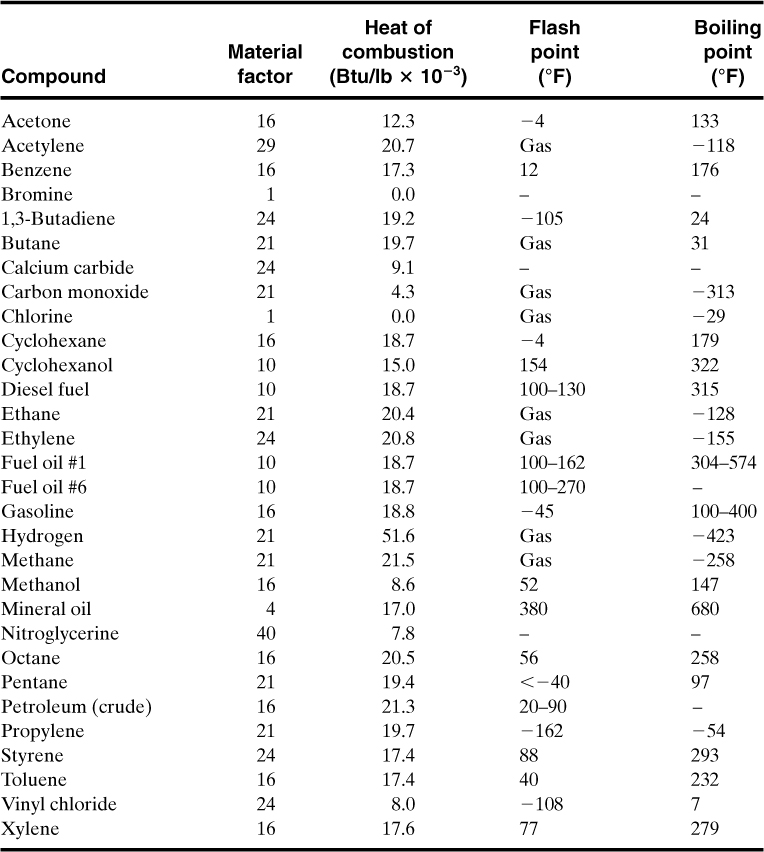
a Selected from Dow’s Fire and Explosion Index Hazard Classification Guide, 7th ed. (New York: American Institute of Chemical Engineers, 1994).
In general, the higher the value of the MF, the more flammable and/or explosive the material. If mixtures of materials are used, the MF is determined from the properties of the mixture. The highest value of the MF under the complete range of operating conditions is suggested. The resulting MF value for the process is written in the space provided at the top of the form in Figure 11-3.
The next step is to determine the general process hazards. Penalties are applied for the following factors:
1. Exothermic reactions that might self-heat
2. Endothermic reactions that could react because of an external heat source such as a fire
3. Material handling and transfer, including pumping and connection of transfer lines
4. Enclosed process units preventing dispersion of escaped vapors
5. Limited access for emergency equipment
6. Poor drainage of flammable materials away from the process unit
Penalties for special process hazards are determined next:
1. Toxic materials, which could impede fire fighting
2. Less than atmospheric pressure operation with a risk of outside air entering
3. Operation in or near the flammable limits
4. Dust explosion risks
5. Higher than atmospheric pressure
6. Low-temperature operation with potential embrittlement of carbon steel vessels
7. Quantity of flammable material
8. Corrosion and erosion of process unit structures
9. Leakage around joints and packings
10. Use of fired heaters, providing a ready ignition source
11. Hot oil heat exchange systems where the hot oil is above its ignition temperature
12. Large rotating equipment, including pumps and compressors
Detailed instructions and correlations for determining the general and special process hazards are provided in the complete Dow F&EI.
The general process hazard factor (F1) and special process hazard factor (F2) are multiplied together to produce a unit hazard factor (F3). The Dow F&EI is computed by multiplying the unit hazard factor by the MF. Table 11-2 provides the degree of hazard based on the index value.
Table 11-2. Determining the Degree of Hazard from the Dow Fire and Explosion Index

The Dow F&EI can be used to determine the consequences of an accident. This includes the maximum probable property damage (MPPD) and the maximum probable days outage (MPDO).
The consequences analysis is completed using the worksheet form shown in Figure 11-4. The computations are completed in the Risk Analysis Summary table at the bottom of the form. The damage radius is first estimated using a correlation published in the complete Dow index. This correlation is based on the previously determined F&EI. The dollar value of the equipment within this radius is determined. Next, a damage factor (based on a correlation provided) is applied to the fraction of the equipment actually damaged by the explosion or fire. Finally, a credit factor is applied based on safety systems. The final number, in dollars, is the MPPD value. This number is used to estimate the MPDO using a correlation. Details on the procedure are available in the complete Dow reference.
The Dow indexes are useful for determining equipment spacing requirements. The F&EI uses an empirical correlation based entirely on the F&EI value to estimate the radius of exposure. It is assumed that any equipment located outside this distance would not be damaged by a fire or explosion. The CEI estimates the hazard distance for chemical exposure based on the emergency response planning guideline (ERPG) values for the particular material released.
Your plant is considering the installation of a new railcar tank unloading facility. The facility will unload nominal 25,000-gal tank cars containing either pure butadiene or cyclohexane. The unloading system will be equipped with an emergency shutdown system with remotely operated block valves. The unloading operation will be done by computer control. The railcars are inerted with nitrogen to a pressure of 40 psig, and the railcar relief system has a set pressure of 75 psig. The unloading operating instructions are written and have been reviewed by the corporate technical staff. A reactive chemicals review has already been completed on the proposed facility. Combustible gas detectors will be located at the unloading station. A deluge system will be installed at the unloading site with an excellent water supply. A diking system will surround three sides of the facility, with any spills directed to a covered impounding area.
Determine the Dow F&EI for this operation, and determine the minimum spacing from adjacent units.
The Dow Index contains most of the data required to complete the evaluation. The data for the chemical species used in this facility are
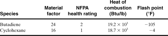
Because the butadiene has the higher MF, it is the material we need to evaluate using the Dow F&EI.
The completed F&EI form is shown in Figure 11-5. Each nonzero item on the form is discussed in what follows.
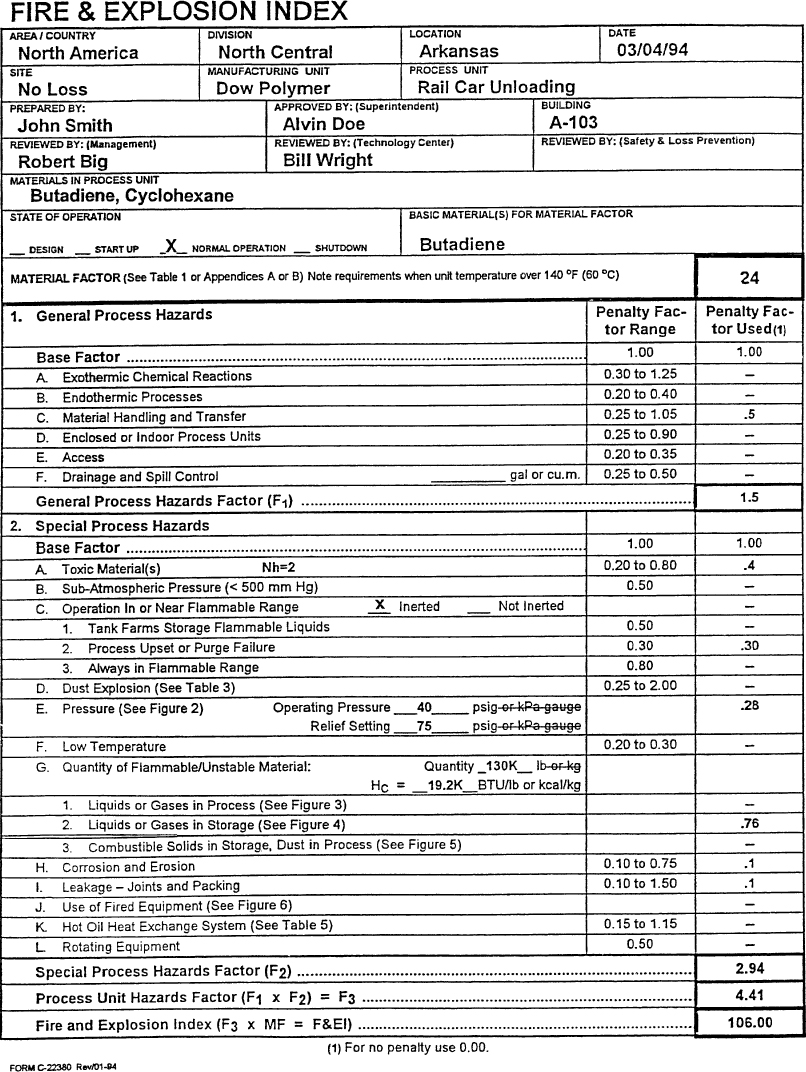
Figure 11-5. The Dow Fire and Explosion Index applied to the railcar unloading facility of Example 11-1.
1.A. Exothermic chemical reactions: The reactive chemical review has determined that an exothermic chemical reaction here is not possible. The penalty is zero.
1.B. Endothermic chemical reactions: This penalty applies only to reactors, so the penalty is zero.
1.C. Material handling and transfer: The index documentation states: “Any loading and unloading operation involving Class I flammables or LPG-type materials where transfer lines are connected and disconnected receives a penalty of 0.50.”
1.D. Enclosed or indoor process units: The unit is outdoors, so the penalty is zero.
1.E. Access: The unit will have emergency access from all sides, so the penalty is zero.
1.F. Drainage and spill control: No penalty is applied because the dike and impounding system is present.
2.A. Toxic materials: The index suggests using a penalty value of 0.20 × NFPA Health Rating. Because the rating is 2, the penalty value is 0.4.
2.B. Subatmospheric pressure: The operation is pressurized, so no penalty is applied here.
2.C. Operation in or near flammable range
1. Tank farms storage flammable liquids: The tanks are inerted with a closed vapor recovery system, so the penalty here is zero.
2. Process upset or purge failure: The unit relies on inert purging to keep it out of the flammable range, so a penalty of 0.30 is applied.
3. Always in flammable range: The process is not in the flammable range during normal operation, so the penalty is zero.
2.D. Dust explosion: No dusts are involved, so the penalty is zero.
2.E. Pressure: The Dow index provides a detailed procedure for determining this penalty. The operating pressure penalty is determined from Figure 2 in the Dow index booklet using the operating pressure. In this case the operating pressure of 40 psig results in a penalty of 0.24. Second, a penalty is determined at the relief set pressure (75 psig), again using Figure 2 in the Dow index booklet. This value is 0.27. The operating pressure penalty is then divided by the set pressure penalty to get a final pressure penalty adjustment. In this case the adjustment is 0.24/0.27 = 0.8889. This is multiplied by the operating pressure penalty to obtain 0.24(0.8889) = 0.2133. Finally, this is multiplied by a correction factor of 1.3 because this is a liquefied flammable gas. The final penalty is 0.2133(1.3) = 0.28.
2.F. Low temperature: Low-temperature operating is not expected, so the penalty is zero.
2.G. Quantity of flammable/unstable material
1. Liquids or gases in process: This is not part of the process, so the penalty is zero.
2. Liquids or gases in storage: The total energy contained within the storage inventory is estimated in order to determine the penalty. This requires the specific gravity of butadiene, which can be found on the MSDS sheet or other reference. This value is 0.6263. Thus the total energy is
(25,000 gal)(8.345 lb/gal)(0.6263) = 130,662 lb,
(1.30 × 10⁵ lb)(19.2 × 10³ Btu/lb) = 2.51 × 10⁹ Btu.
From Figure 4, curve B, in the Dow index booklet, the penalty is 0.76.
3. Combustible solids in storage, dust in process: No solids are present here, so the penalty is zero.
2.H. Corrosion and erosion: Corrosion and erosion are expected to be less than 0.5 mil/yr. Thus the penalty is 0.10.
2.I. Leakage—joints and packing: The pump and gland seals are expected to have some small but minor leakage. Thus the penalty here is 0.10.
2.J. Use of fired equipment: No fired equipment is present, so the penalty is zero.
2.K. Hot oil heat exchange system: Not present, so the penalty is zero.
2.L. Rotating equipment: No large rotating equipment is present, so the penalty is zero.
These penalties and factors are summarized in Figure 11-5. The resulting calculation shows an F&EI value of 106, which means that this unloading station is an intermediate hazard.
Figure 7 in the Dow index booklet provides the radius of exposure based on the F&EI value. For this case the radius is 90 ft. Thus the unloading station must be located a minimum of 90 ft from any other equipment or processes.
The Dow CEI is a simple method of rating the relative acute health hazard potential for people in neighboring plants or communities arising from possible chemical release incidents.
To use the CEI, the following items are required:
• An accurate plot plan of the plant and the surrounding area
• A simplified process flow sheet showing the containment vessels, major piping, and chemical inventories
• Physical and chemical properties of the materials investigated
• ERPG values, from Table 5-6
• The CEI guide
• The CEI form shown in Figure 11-6
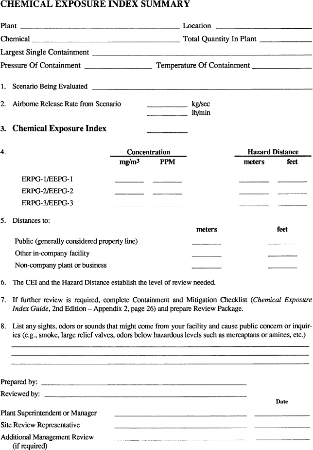
Figure 11-6. Form used for the Dow Chemical Exposure Index. Source: Dow’s Chemical Exposure Index Guide (New York: American Institute of Chemical Engineers, 1998). Reproduced by permission of the American Institute of Chemical Engineers.
A flowchart of the CEI procedure is shown in Figure 11-7. The procedure begins with a definition of possible release incidents. These include releases from pipes, hoses, pressure relief devices relieving directly to the atmosphere, vessels, and tank overflows and spills. The CEI guide has detailed guidelines for these incidents, as shown in Table 4-6. The incidents are used with a number of simplified source models provided in the Dow guide4 to estimate the release rate of material. The ERPGs are then used with a simplified dispersion model to determine the CEI value and downwind hazard distances resulting from the release.
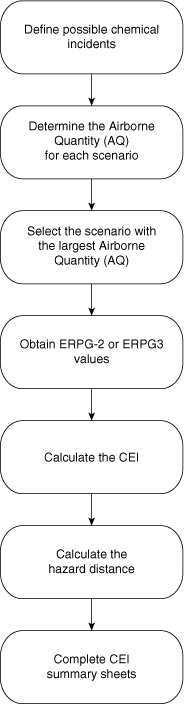
Figure 11-7. Procedure for calculating the Chemical Exposure Index (CEI). Source: Dow’s Chemical Exposure Index Guide (New York: American Institute of Chemical Engineers, 1998).
Hazards surveys are suitable for identifying hazards associated with equipment design, layout, material storage, and so forth. They are not suitable for identifying hazards resulting from improper operation or upset conditions. On the other hand, this approach is fairly rigorous, requires little experience, is easy to apply, and provides a quick result.
11-3. Hazards and Operability Studies
The HAZOP study is a formal procedure to identify hazards in a chemical process facility.5 The procedure is effective in identifying hazards and is well accepted by the chemical industry.
The basic idea is to let the mind go free in a controlled fashion in order to consider all the possible ways that process and operational failures can occur.
Before the HAZOP study is started, detailed information on the process must be available. This includes up-to-date process flow diagrams (PFDs), process and instrumentation diagrams (P&IDs), detailed equipment specifications, materials of construction, and mass and energy balances.
The full HAZOP study requires a committee composed of a cross-section of experienced plant, laboratory, technical, and safety professionals. One individual must be a trained HAZOP leader and serves as the committee chair. This person leads the discussion and must be experienced with the HAZOP procedure and the chemical process under review. One individual must also be assigned the task of recording the results, although a number of vendors provide software to perform this function on a personal computer. The committee meets on a regular basis for a few hours each time. The meeting duration must be short enough to ensure continuing interest and input from all committee members. A large process might take several months of biweekly meetings to complete the HAZOP study. Obviously, a complete HAZOP study requires a large investment in time and effort, but the value of the result is well worth the effort.
The HAZOP procedure uses the following steps to complete an analysis:
1. Begin with a detailed flow sheet. Break the flow sheet into a number of process units. Thus the reactor area might be one unit, and the storage tank another. Select a unit for study.
2. Choose a study node (vessel, line, operating instruction).
3. Describe the design intent of the study node. For example, vessel V-1 is designed to store the benzene feedstock and provide it on demand to the reactor.
4. Pick a process parameter: flow, level, temperature, pressure, concentration, pH, viscosity, state (solid, liquid, or gas), agitation, volume, reaction, sample, component, start, stop, stability, power, inert.
5. Apply a guide word to the process parameter to suggest possible deviations. A list of guide words is shown in Table 11-3. Some of the guide word process parameter combinations are meaningless, as shown in Tables 11-4 and 11-5 for process lines and vessels.
Table 11-3. Guide Words Used for the HAZOP Procedure

Table 11-4. Valid Guide Word and Process Parameter Combinations for Process Lines (x’s represent valid combinations)
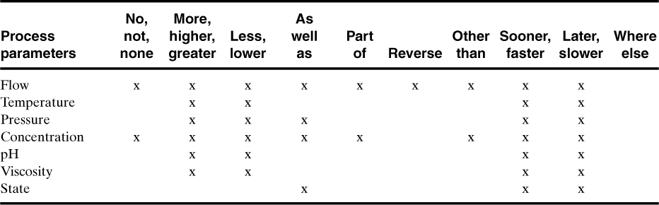
Table 11-5. Valid Guide Word and Process Parameter Combinations for Process Vessels (x’s represent valid combinations)

6. If the deviation is applicable, determine possible causes and note any protective systems.
7. Evaluate the consequences of the deviation (if any).
8. Recommend action (what? by whom? by when?).
9. Record all information.
10. Repeat steps 5 through 9 until all applicable guide words have been applied to the chosen process parameter.
11. Repeat steps 4 through 10 until all applicable process parameters have been considered for the given study node.
12. Repeat steps 2 through 11 until all study nodes have been considered for the given section and proceed to the next section on the flow sheet.
The guide words AS WELL AS, PART OF, and OTHER THAN can sometimes be conceptually difficult to apply. AS WELL AS means that something else happens in addition to the intended design intention. This could be boiling of a liquid, transfer of some additional component, or the transfer of some fluid somewhere else than expected. PART OF means that one of the components is missing or the stream is being preferentially pumped to only part of the process. OTHER THAN applies to situations in which a material is substituted for the expected material, is transferred somewhere else, or the material solidifies and cannot be transported. The guide words SOONER THAN, LATER THAN, and WHERE ELSE are applicable to batch processing.
An important part of the HAZOP procedure is the organization required to record and use the results. There are many methods to accomplish this and most companies customize their approach to fit their particular way of doing things.
Table 11-6 presents one type of basic HAZOP form. The first column, denoted “Item,” is used to provide a unique identifier for each case considered. The numbering system used is a number-letter combination. Thus the designation “1A” would designate the first study node and the first guide word. The second column lists the study node considered. The third column lists the process parameter, and the fourth column lists the deviations or guide words. The next three columns are the most important results of the analysis. The first column lists the possible causes. These causes are determined by the committee and are based on the specific deviation–guide word combination. The next column lists the possible consequences of the deviation. The last column lists the action required to prevent the hazard from resulting in an accident. Notice that the items listed in these three columns are numbered consecutively. The last several columns are used to track the work responsibility and completion of the work.
Table 11-6. HAZOP Form for Recording Data

Consider the reactor system shown in Figure 11-8. The reaction is exothermic, so a cooling system is provided to remove the excess energy of reaction. In the event that the cooling function is lost, the temperature of the reactor would increase. This would lead to an increase in reaction rate, leading to additional energy release. The result would be a runaway reaction with pressures exceeding the bursting pressure of the reactor vessel.
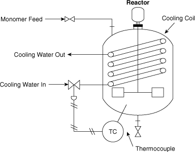
Figure 11-8. An exothermic reaction controlled by cooling water.
The temperature within the reactor is measured and is used to control the cooling water flow rate by a valve.
Perform a HAZOP study on this unit to improve the safety of the process. Use as study nodes the cooling coil (process parameters: flow and temperature) and the stirrer (process parameter: agitation).
The guide words are applied to the study node of the cooling coils and the stirrer with the designated process parameters.
The HAZOP results are shown in Table 11-7, which is only a small part of the complete analysis.
Table 11-7. HAZOP Study Applied to the Exothermic Reactor of Example 11-2.
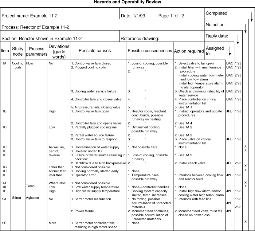
The potential process modifications resulting from this study (Example 11-2) are the following:
• Install a high-temperature alarm to alert the operator in the event of cooling function loss
• Install a high-temperature shutdown system (this system would automatically shut down the process in the event of a high reactor temperature; the shutdown temperature would be higher than the alarm temperature to provide the operator with the opportunity to restore cooling before the reactor is shut down)
• Install a check valve in the cooling line to prevent reverse flow (a check valve could be installed both before and after the reactor to prevent the reactor contents from flowing upstream and to prevent the backflow in the event of a leak in the coils)
• Periodically inspect the cooling coil to ensure its integrity
• Study the cooling water source to consider possible contamination and interruption of supply
• Install a cooling water flow meter and low-flow alarm (which will provide an immediate indication of cooling loss)
In the event that the cooling water system fails (regardless of the source of the failure), the high-temperature alarm and emergency shutdown system prevents a runaway reaction. The review committee performing the HAZOP study decided that the installation of a backup controller and control valve was not essential. The high-temperature alarm and shutdown system prevents a runaway reaction in this event. Similarly, a loss of coolant water source or a plugged cooling line would be detected by either the alarm or the emergency shutdown system. The review committee suggested that all coolant water failures be properly reported and that if a particular cause occurred repeatedly, then additional process modifications were warranted.
Example 11-2 demonstrates that the number of suggested process changes is great, although only a single process intention is considered.
The advantage to this approach is that it provides a more complete identification of the hazards, including information on how hazards can develop as a result of operating procedures and operational upsets in the process. Companies that perform detailed HAZOPs studies find that their processes operate better and have less downtime, that their product quality is improved, that less waste is produced, and that their employees are more confident in the safety of the process. The disadvantages are that the HAZOP approach is tedious to apply, requires considerable staff time, and can potentially identify hazards independent of the risk.
11-4. Safety Reviews
Another method that is commonly used to identify safety problems in laboratory and process areas and to develop solutions is the safety review. A “safety review” brings together a diverse group of people to review a project or operation with a broad safety perspective. The review team identifies and eliminates hazards in the design and procedures. The review process includes finding initiating events or upset conditions that can cause an accident. The team subsequently develops recommendations including new, modified, and improved equipment, controls, and procedures (operating, emergency, maintenance, etc.). The focus should be on developing a high-quality review that prevents personnel injuries, equipment damage or failures, and business interruptions.
Safety reviews include a review of previous accidents and incidents in similar plants or processes. Some incidents are referred to as “near-misses,” meaning that a serious consequence did not occur but could have. Incident investigations or case histories contain actions to prevent a recurrence of similar incidents.6. They identify the underlying causes of incidents and outline steps to be implemented to prevent similar events. The study of previous accident and incident reports helps the reviewers avoid repeating past mistakes; that is, learn from history or you’re doomed to repeat it.
The review should be conducted periodically during the entire life of a project. The first review (before the detailed design) is the most important, because changes in the original design are less expensive compared to changes in an operating plant. Often an informal safety review will identify the need for a more detailed review, such as a formal safety review described in Section 11-3, or other PHA methods described in Section 11-5.7,8 After startup, the periodic reviews should be conducted about every year or whenever the process adds new equipment, new chemicals, new reactions, and new procedures.
A safety review is a cooperative, constructive, and creative process that improves the safety and performance of the process. Safety reviews are positive experiences, and good reviews prevent the dreadful experiences associated with accidents and accident investigations. An especially high-quality review is not limited to environmental and safety consequences but is expanded to include operability and product quality concerns.9.
In all of the methods mentioned above, checklists are recommended to facilitate the review process. A typical checklist is shown in Figure 11-2. The reviewers should develop checklists specifically tailored to the plant and personnel conducting the review. An adaptation of Figure 11-2 is shown in Table 11-8.
Table 11-8. Checklist for Informal and Formal Safety Reviews

The first review uses a checklist for each of the six phases of a project’s life (see Table 11-8, that is, design construction, startup, operation, cleaning, and shutdown.7 The periodic and follow-up reviews include the last four items: startup, operation, cleaning, and shutdown.
There are two types of safety reviews: the informal and the formal.
Informal Review
The informal safety review is used for small changes to existing processes and for small bench-scale or laboratory processes. The informal safety review procedure usually involves just two or three people. It includes the individual responsible for the process and one or two others not directly associated with the process but experienced with proper safety procedures. The idea is to provide a lively dialogue where ideas can be exchanged and safety improvements can be developed.
The reviewers simply meet in an informal fashion to examine the process equipment and operating procedures and to offer suggestions on how the safety of the process might be improved. Significant improvements should be summarized in a memo for others to reference in the future. The improvements must be implemented before the process is operated.
Consider the laboratory reactor system shown in Figure 11-9. This system is designed to react phosgene (COCl2) with aniline to produce isocyanate and HCl. The reaction is shown in Figure 11-10. The isocyanate is used for the production of foams and plastics.
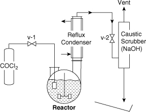
Figure 11-9. Original design of phosgene reactor before informal safety review.
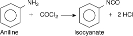
Figure 11-10. Reaction stoichiometry for phosgene reactor.
Phosgene is a colorless vapor with a boiling point of 46.8°F. Thus it is normally stored as a liquid in a container under pressure above its normal boiling point temperature. The TLV for phosgene is 0.1 ppm, and its odor threshold is 0.5–1 ppm, well above the TLV.
Aniline is a liquid with a boiling point of 364°F. Its TLV is 2 ppm. It is absorbed through the skin.
In the process shown in Figure 11-9 the phosgene is fed from the container through a valve into a fritted glass bubbler in the reactor. The reflux condenser condenses aniline vapors and returns them to the reactor. A caustic scrubber is used to remove the phosgene and HCl vapors from the exit vent stream. The complete process is contained in a hood.
Conduct an informal safety review of this process.
The safety review was completed by two individuals. The final process design is shown in Figure 11-11. The changes and additions to the process are as follows:
1. Vacuum is added to reduce boiling temperature
2. Relief system is added with an outlet to a scrubber to prevent hazards resulting from a plugged fritted glass bubbler
3. Flow indicator provides visual indication of flow
4. Bubblers are used instead of scrubbers because they are more effective
5. Ammonium hydroxide bubbler is more effective for absorbing phosgene
6. Trap catches liquid phosgene
7. Pail of caustic is added (the phosgene cylinder would be dumped into this pail in the event of a cylinder or valve leak; the caustic would absorb the phosgene)
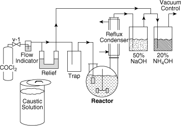
Figure 11-11. Final design of phosgene reactor after informal safety review.
In addition, the reviewers recommended the following: (1) Hang phosgene indicator paper around the hood, room, and operating areas (this paper is normally white but turns brown when exposed to 0.1 ppm of phosgene), (2) use a safety checklist, daily, before the process is started, and (3) post an up-to-date process sketch near the process.
Formal Review
The formal safety review is used for new processes, substantial changes in existing processes, and processes that need an updated review. The formal safety review is a three-step procedure. This consists of preparing a detailed formal safety review report, having a committee review the report and inspect the process, developing improvements in the design and operating procedures, and implementing the recommendations. The formal safety review report includes the following sections:
I. Introduction
A. Overview or summary: Provides a brief summary of the results of the formal safety review. This is done after the formal safety review is complete.
B. Process overview or summary: Provides a brief description of the process with an emphasis on the major hazards in the operation.
C. Reactions and stoichiometry: Provides the chemical reaction equations and stoichiometry.
D. Engineering data: Provides operating temperatures, pressures, and relevant physical property data for the materials used.
II. Raw materials and products: Refers to specific hazards and handling problems associated with the raw materials and products. Discusses procedures to minimize these hazards.
III. Equipment setup
A. Equipment description: Describes the configuration of the equipment. Sketches of the equipment are provided.
B. Equipment specifications: Identifies the equipment by manufacturer name and model number. Provides the physical data and design information associated with the equipment.
IV. Procedures
A. Normal operating procedures: Describes how the process is operated.
B. Safety procedures: Provides a description of the unique concerns associated with the equipment and materials and specific procedures used to minimize the risk. This includes:
1. Emergency shutdown: Describes the procedure used to shut down the equipment if an emergency should occur. This includes major leaks, reactor runaway, and loss of electricity, water, and air pressure.
2. Fail-safe procedures: Examines the consequences of utility failures, such as loss of steam, electricity, water, air pressure, or inert padding. Describes what to do for each case so that the system fails safely.
3. Major release procedures: Describes what to do in the event of a major spill of toxic or flammable material.
C. Waste disposal procedure: Describes how toxic or hazardous materials are collected, handled, and disposed.
D. Cleanup procedures: Describes how to clean the process after use.
V. Safety checklist: Provides the complete safety checklist for the operator to complete before operation of the process. This checklist is used before every startup.
VI. Material safety data sheets: Provided for each hazardous material used.
A toluene water wash process is shown in Figure 11-12. This process is used to clean water-soluble impurities from contaminated toluene. The separation is achieved with a Podbielniak centrifuge, or Pod, because of a difference in densities. The light phase (contaminated toluene) is fed to the periphery of the centrifuge and travels to the center. The heavy phase (water) is fed to the center and travels countercurrent to the toluene to the periphery of the centrifuge. Both phases are mixed within the centrifuge and separated countercurrently. The extraction is conducted at 190°F.
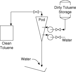
Figure 11-12. Toluene water wash process before formal safety review.
The contaminated toluene is fed from a storage tank into the Pod. The heavy liquid out (contaminated water) is sent to waste treatment and the light liquid out (clean toluene) is collected in a 55-gal drum.
Perform a formal safety review of this process.
The complete safety review report is provided in Appendix D. Figure 11-13 shows the modified process after the formal safety review has been completed. The significant changes or additions added as a result of the review are as follows:
1. Add grounding and bonding to all collection and storage drums and process vessels
2. Add inerting and purging to all drums
3. Add elephant trunks at all drums to provide ventilation
4. Provide dip legs in all drums to prevent the free fall of solvent resulting in the generation and accumulation of static charge
5. Add a charge drum with grounding, bonding, inerting, and ventilation
6. Provide a vacuum connection to the dirty toluene storage for charging
7. Add a relief valve to the dirty toluene storage tank
8. Add heat exchangers to all outlet streams to cool the exit solvents below their flash point (this must include temperature gauges to ensure proper operation)
9. Provide a waste water collection drum to collect all waste water that might contain substantial amounts of toluene from upset conditions
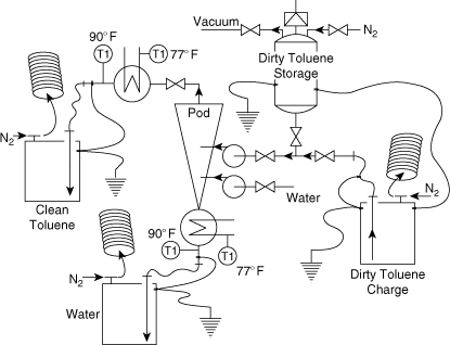
Figure 11-13. Toluene water wash process after formal safety review.
Additional changes were made in the operating and emergency procedure. They included
1. Checking the room air periodically with colorimetric tubes to determine whether any toluene vapors are present
2. Changing the emergency procedure for spills to include (a) activating the spill alarm, (b) increasing the ventilation to high speed, and (c) throwing the sewer isolation switch to prevent solvent from entering the main sewer lines
The formal safety review can be used almost immediately, is relatively easy to apply, and is known to provide good results. However, the committee participants must be experienced in identifying safety problems. For less experienced committees, a more formal HAZOP study may be more effective in identifying the hazards.
11-5. Other Methods
Other methods that are available for identifying hazards are the following:
1. “What if” analysis: This less formal method of identifying hazards applies the words “what if” to a number of areas of investigation. For instance, the question might be, What if the flow stops? The analysis team then decides what the potential consequences might be and how to solve any problems.
2. Human error analysis: This method is used to identify the parts and the procedures of a process that have a higher than normal probability of human error. Control panel layout is an excellent application for human error analysis because a control panel can be designed in such a fashion that human error is inevitable.
3. Failure mode, effects, and criticality analysis (FMECA): This method tabulates a list of equipment in the process along with all the possible failure modes for each item. The effect of a particular failure is considered with respect to the process.
Suggested Reading
Center for Chemical Process Safety (CCPS), Guidelines for Chemical Process Quantitative Risk Analysis, (CPQRA), 2nd ed. (New York: Center for Chemical Process Safety, AIChE, 2000).
Center for Chemical Process Safety (CCPS), Guidelines for Developing Quantitative Safety Risk Criteria (New York: Center for Chemical Process Safety, AIChE, 2009).
Center for Chemical Process Safety (CCPS), Guidelines for Hazard Evaluation Procedures, 3rd ed. (Hoboken, NJ: John Wiley & Sons, 2008).
Center for Chemical Process Safety (CCPS), Guidelines for Risk-Based Process Safety (New York: Center for Chemical Process Safety, AIChE, 2008).
Dow’s Fire and Explosion Index Hazard Classification Guide, 7th ed. (New York: American Institute of Chemical Engineers, 1994).
Trevor A. Kletz, HAZOP and HAZAN, 3d ed. (Warwickshire, England: Institution of Chemical Engineers, 1992).
S. Mannan, ed., Lees’ Loss Prevention in the Process Industries, 3rd ed. (London: Butterworth Heinemann, 2005).
Problems
11-1. The hydrolysis of acetic anhydride is being studied in a laboratory-scale continuously stirred tank reactor (CSTR). In this reaction acetic anhydride [(CH3CO)2O] reacts with water to produce acetic acid (CH3COOH).
The concentration of acetic anhydride at any time in the CSTR is determined by titration with sodium hydroxide. Because the titration procedure requires time (relative to the hydrolysis reaction time), it is necessary to quench the hydrolysis reaction as soon as the sample is taken. The quenching is achieved by adding an excess of aniline to the sample. The quench reaction is
(CH3CO)2 + C6H5NH2 → CH3COOH + C6H5NHCOCH3.
The quenching reaction also forms acetic acid, but in a different stoichiometric ratio from the hydrolysis reaction. Thus it is possible to determine the acetic anhydride concentration at the time the sample was taken.
The initial experimental design is shown in Figure 11-14. Water and acetic anhydride are gravity-fed from reservoirs and through a set of rotameters. The water is mixed with the acetic anhydride just before it enters the reactor. Water is also circulated by a centrifugal pump from the temperature bath through coils in the reactor vessel. This maintains the reactor temperature at a fixed value. A temperature controller in the water bath maintains the temperature to within 1°F of the desired temperature.

Figure 11-14. Acetic anhydride reactor system.
Samples are withdrawn from the point shown and titrated manually in a hood.
a. Develop a safety checklist for use before operation of this experiment.
b. What safety equipment must be available?
c. Perform an informal safety review of the experiment. Suggest modifications to improve the safety.
11-2. Perform a HAZOP study on the laboratory process of Problem 11-1. Consider the intention “reactant flow to reactor” for your analysis. What specific recommendations can you make to improve the safety of this experiment?
11-3. A heat exchanger is used to heat flammable, volatile solvents, as shown in Figure 11-15. The temperature of the outlet stream is measured by a thermocouple, and a controller valve manipulates the amount of steam to the heat exchanger to achieve the desired set point temperature.
a. Identify the study nodes of the process.
b. Perform a HAZOP study on the intention “hot solvent from heat exchanger.” Recommend possible modifications to improve the safety of the process.

Figure 11-15. Volatile solvent heating system.
11-4. A gas-fired furnace is shown in Figure 11-16. The hot combustion gases pass through a heat exchanger to heat fresh air for space heating. The gas flow is controlled by an electric solenoid valve connected to a thermostat. The gas is ignited by a pilot light flame. A high-temperature switch shuts off all gas in the event of high temperature in the fresh air plenum.
a. Determine the various ways in which this system can fail, leading to excessive heating of the plenum and possible fire.
b. What type of valve (normally open or normally closed) is recommended for the gas supply?
c. What is the most likely failure mode?
d. A problem can also arise because of failure of the pilot light, leading to combustible gases in the furnace, heat exchanger, and chimney. Suggest at least two ways to prevent this problem.
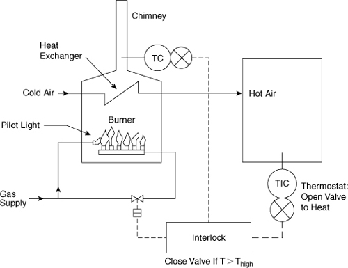
Figure 11-16. Furnace control system.
11-5. Beverage dispensers are notorious for either taking one’s money or not delivering the proper beverage. Consider a beverage dispenser that delivers a paper cup, ice, and beverage (composed of syrup and water) in a sequential order. The machine also makes change.
Identify as many failure modes as possible. Use the HAZOP guide words to identify additional possibilities.
11-6. World War II submarines used torpedo tubes with outer and inner doors. The torpedo was loaded into the tube from the torpedo room using the inner door. The inner door was then closed, the outer door opened, and the torpedo launched.
One problem was ensuring that the outer door was closed before the inner door was opened. Because no direct visible check was possible, a small pipe and valve were attached to the top of the torpedo tube in the torpedo room. Before opening the inner door, the valve was opened momentarily to check for the presence of pressurized water in the tube. The presence of pressurized water was a direct indication that the outer door was open.
Determine a failure mode for this system, leading to the inner door being opened when the outer door was open, resulting in flooding of the torpedo room and possible sinking of the sub.
11-7. Five process pumps are lined up in a row and numbered as shown in Figure 11-17. Can you identify the hazard? A similar layout led to a serious accident by a maintenance worker who was sprayed by hot solvent when he disconnected a pump line on the wrong pump. An accident like this might be attributed to human error but is really a hazard resulting from poor layout.

Figure 11-17. Pump layout.
11-8. A good acronym in chemical plant design is KISS—Keep It Simple, Stupid! This also applies to hazards. Complicated designs are almost always more hazardous than simple ones.
Figure 11-18 shows a sump designed to collect process fluids. The level controller and pump ensure that the sump level is maintained below a maximum height. Can you suggest a much simpler system?
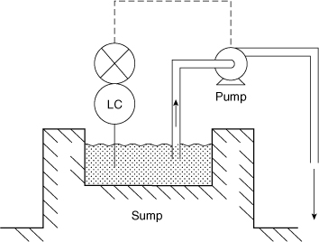
Figure 11-18. Sump level control system.
11-9. Storage tanks typically are not capable of withstanding much pressure or vacuum. Standard storage tanks are designed for a maximum of 2.5 in of water gauge vacuum (0.1 psi) and about 6 in of water gauge pressure (0.2 psi).
A welding operation was to occur on the roof of a storage vessel. The tank contained a flammable, volatile liquid. The roof was equipped with a vent pipe with a flame arrestor.
The foreman recognized a possible hazard from flammable vapor escaping from the vent pipe and igniting on the sparks from the welding operation. He connected a hose to the vent at the top of the tank and ran the hose down to the ground. Because the flammable vapors were water soluble, he stuck the end of the hose in a drum full of water. During a subsequent operation that involved emptying the tank, an accident occurred. Can you explain what happened and how?
11-10. Figure 11-19 shows a storage tank blanketed with nitrogen. This configuration resulted in an explosion and fire because of loss of inert material. Can you explain why?
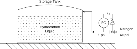
Figure 11-19. Nitrogen padding system for a storage tank.
11-11. Figure 11-20 shows two tanks in series, both with independent level controllers. This configuration will result in the lower tank inevitably overflowing. Can you explain why?

Figure 11-20. Level tanks in series.
11-12. Develop a safety checklist for the system described in Example 11-3 and shown in Figure 11-14. The intention of the checklist is to ensure the system is safe before operation.
11-13. Prepare a formal safety review memo for the gas-fired furnace described in Problem 11-4 and shown in Figure 11-16. This memo will be given to each committee member before the formal safety review committee meeting.
11-14. Describe an informal safety review process for using a cylinder of phosgene to charge gaseous phosgene to a reactor. Review up to the reactor only.
11-15. In Figure 11-8, identify the study nodes of the reactor process, as shown.
11-16. “Fail-safe” is a concept used to specify the position of process instrumentation in the event of power, air pressure, or other utility failures. For instance, the valve supplying cooling water to a chemical reactor would fail in the open position (“fail open”) in the event of a power failure. This would provide maximum cooling to the reactor and prevent dangerous high temperatures in the vessel.
Specify the proper fail-safe positions for the valves in the following equipment. Specify either fail open or fail close.
a. A flammable solvent is heated by steam in a heat exchanger. The valve controls the flow of steam to the exchanger.
b. A valve controls the flow rate of reactant to a reactor vessel. The reaction is exothermic.
c. A valve controls the flow rate of reactant to a reactor vessel. The reaction is endothermic.
d. A valve controls the flow of natural gas to a utility furnace in a power station.
e. A remotely operated valve is connected to a drain on a storage tank.
f. A remotely operated valve is used to fill a tank from a supply line.
g. A valve controls combustion air to a furnace.
h. A valve controls the pressure in a steam header.
11-17. Interlocks are used to ensure that operations in a chemical plant are performed in the proper sequence. Interlocks can be mechanical or electronic. In many cases they can be as simple as a lock and key.
Specify the simplest mechanical interlock capable of achieving the following functions:
a. A valve cannot be closed until a furnace is shut down.
b. Two valves cannot both be closed at the same time.
c. A valve must be closed before a pump is started.
d. Feed to a reactor cannot be started until the reactor vessel stirring motor is activated.
11-18. A process operator is given the following instructions: “Charge 10 lb of catalyst into batch reactor A at 3 hr into the cycle.” Determine at least 15 ways in which the operator might fail to perform the instructions correctly.
11-19. Thermocouples in chemical plants are usually found in sheaths. These sheaths protect the thermocouple and also allow the thermocouple to be removed and replaced without shutting down the process. One chemical plant had some thermocouples that did not have sheaths, although they looked like the sheathed type. This led to an accidental release of toxic and flammable material. Can you explain why?
11-20. Liquid levels in storage tanks are frequently determined by measuring the pressure at the bottom of the tank. In one such tank the material stored in the tank was changed and an overflow resulted. Why?
11-21. La La Pharmaceuticals has recently discovered a new drug, Lalone, in their chemical laboratories. Lalone is expected to be a blockbuster drug, raking in billions of dollars each year. For the next stage of clinical studies over 50 kg of Lalone is required, and La La Pharmaceuticals has decided to produce this in their existing pilot plant operations in Lala Land. As the safety director for the pilot plant operations, you are in charge of ensuring the safety of all operations.10
During a meeting with the chemist who synthesized Lalone in the laboratory, you have learned the following: (1) Lalone is a fine, white powder; (2) Lalone is synthesized by a batch process through a series of four major steps—three sets of reactions to produce intermediates, followed by drying to produce Lalone (all reactions are carried out in the liquid phase and require acetone as a solvent); (3) the chemical reactions are not fully understood, and most physical and chemical properties are not known; (4) so far, Lalone has been manufactured only in the laboratory and in small quantities (less than 50 g); (5) management wants the pilot plant operations to be started as soon as possible; and (6) the Engineering Division has already started writing the operating procedures for the eventual process.
As the safety director of the pilot plant:
a. Based on your safety knowledge and experience, identify the major hazards in this process that you would be concerned about.
b. Describe how you would structure a hazard study for the Lalone manufacturing process.
c. What additional information will you need to conduct the hazard analysis study?
11-22. An operator was told to control the temperature of a reactor at 60°C. He set the set point of the temperature controller at 60. The scale actually indicated 0–100% of a temperature range of 0–200°C. This caused a runaway reaction that overpressured the vessel. Liquid was discharged and injured the operator. What was the set point temperature the operator actually set?
11-23. Pneumatic process equipment operates in the range of 3–15 psig. Thus, for example, a signal of 3 psig might represent 0 psig in the process and 15 psig might represent 1200 psig in the process.
A pneumatic pressure gauge was designed to operate in the range of 3–15 psig, corresponding to the pneumatic signal sent from the plant. However, the scale printed on the gauge read 0 to 1200 psig, corresponding to the actual process pressures.
This gauge was accidentally overpressured, resulting in an accident. What happened?
11-24. A light in the control room of a chemical plant indicated whether a valve was closed or not. In reality it indicated only the status of the signal being sent to the valve. The valve did not close when it should have, and the plant exploded. Why? How would you prevent this problem?
11-25. A coffee maker has a reservoir where a quantity of clean water is poured. A small heater percolates the water up to the top of the coffee maker, where it drips down through the coffee grounds and filter assembly. The coffee product is collected in the coffee pot.
a. Draw a sketch of the coffee machine, and identify the study nodes.
b. Perform a HAZOP study on a common coffee maker. Use as a design objective hot, fresh-brewed coffee in the coffee pot.
11-26. (This problem requires student access to the Dow Fire and Explosion Index manual.) In a devolatilizer, a solvent (60% cyclohexane and 40% pentane) is removed from a polymer and sent to the solvent recycle section of the plant for treatment and recovery. The devolatilizer is located in an open structure with good access for fire fighting. The process area has a 1% sloping concrete surface with a remote impounding area capable of handling all of a spill and 30 min of fire water. The process is run above the flash point of the solvent at 300 mm Hg. The vessel has a relief device set at 50 psig. Assume a potential spill of 8000 lb of flammable material with a heat of combustion of 19.4 × 10³ Btu/lb.
The process unit has many loss control features. The plant has a diesel emergency power generator with an emergency cooling system. The plant is also under computer control with emergency shutdown based on redundant inputs. Vacuum is always broken with nitrogen. The process has complete, written, and up-to-date operating instructions. A reactive chemicals review was completed recently. The process has several interlocks to prevent polymerization.
The process area has combustible gas detectors, fireproofing, and a water deluge system. Cable trays are protected with deluge, and portable dry chemical extinguishers are in the process area. Diesel-powered fire water pumps can provide a maximum fire water demand for 4 hr.
a. Determine the Dow F&EI value for this process to estimate the relative degree of hazard.
b. Assuming an equipment value within the radius of exposure of $1 million, estimate the maximum probable property damage.
c. Assuming a product value of $1.50 per pound and an annual plant production rate of 35 million lb, estimate the business interruption loss.
11-27. (This problem requires student access to the Dow Fire and Explosion Index manual.) Consider a butadiene storage vessel in a tank farm area containing butadiene, cyclohexane, isopentane, styrene, and isopropene. The maximum butadiene storage capacity is 100,000 gal. The normal pressure of the butadiene storage vessel is 15 psig, with the relief valve set at 50 psig. The butadiene storage is diked separately from the other materials. The butadiene storage area is equipped with a chilled glycol cooling system that can be operated from an emergency generator if necessary. The transfer operations in and out of storage are monitored by computer control with emergency shutdown capability. The vapor space in the vessel is inerted. Operating instructions are current, and the system has been through a recent reactive chemicals review.
The storage system has remotely operated emergency block valves on all transfer lines into and out of the tank. The storage area has the required drainage to direct a spill away from the tank. Backflow protection has been installed and is tested to prevent backflow into the transfer line and storage.
Loss control features include combustible gas detectors installed around the containment area and transfer system. A diesel-driven fire pump is capable of handling the emergency demand for 4 hr. A water deluge system has been installed around the storage tank and transfer pump.
The specific gravity of the butadiene is 0.6263.
a. Determine the Dow F&EI value for this process to estimate the relative degree of hazard.
b. Assuming an equipment value within the radius of exposure of $1 million, estimate the maximum probable property damage.
c. Assuming a product value of $2.00 per pound for this plant and an annual production rate of 10 million lb, estimate the business interruption loss.
11-28. Exothermic chemical reactions are frequently dangerous because of the potential for a runaway reaction. Cooling coils are provided in batch reactors to remove the energy of reaction. In the event of a cooling water failure, the reactor temperature rises, resulting in a higher reaction rate and higher energy generation. The result is a runaway reaction. During a runaway reaction, the temperature can rise quickly, resulting in dangerous pressures within the reactor and a possible explosion.
Loss of cooling can be detected by measuring the temperature within the reactor and sounding an alarm. Frequently, by the time the alarm sounds, it is too late. Design a better instrumentation and alarm configuration to detect loss of cooling more directly. Draw the instrumentation diagram.
11-29. A flammable liquid is to be stored in a large storage vessel. Two vessels are available. One vessel is called a weak seam roof tank, with the weakest part of the vessel being the welded seam between the roof and the vertical wall of the tank. The other vessel is a domed roof tank, with the weakest part being the seam along the bottom of the tank. Which tank is the better choice for storing this material?
11-30. Your manufacturing plant has purchased a number of robots to facilitate production. What are the main hazards associated with robots? What are some effective safeguards against these hazards?11
11-31. As described in Section 11-4, checklists are used to facilitate a high-quality safety review, and the checklists are tailored for a specific process and a specific group of reviewers (for example, experienced or inexperienced reviewers). Tailor a checklist for a group of chemical engineering students who are preparing to review a new ChemE Car for the annual AIChE ChemE Car competition.
11-32. Safety reviews should include a review and study of previous incidents and accidents, as described in Section 11-4. Part of the solution to Problem 11-31 includes a review of previous accidents. Summarize the accidents that have previously occurred in AIChE ChemE Car competitions, and state the teaching relevant to new competitors. (See ChemE Car Safety, Workshop Presentation (PDF), www.SACHE.org.)