Chapter 14. Case Histories
Case histories are written descriptions of accidents, including the causes, consequences, and methods required to prevent similar events. They are descriptions written by plant managers and operating personnel. These are the people with the hands-on experience, the ones who know and appreciate the accident and accident prevention methods.
The study of case histories is important in the area of safety. To paraphrase G. Santayana, one learns from history or is doomed to repeat it. This is especially true for safety; anyone working in the chemical industry can learn from case histories and avoid hazardous situations or ignore history and be involved in potentially life-threatening accidents.
In this chapter we cover case histories as reported in the literature. References are provided for more thorough studies. The objective of this chapter is to illustrate, through actual case histories, the importance of applying the fundamentals of chemical process safety.
These case histories are categorized into five sections:
• Training
The cause of a specific accident frequently places it in more than one category. Each of these sections includes descriptions of several accidents and a summary of the lessons learned.
The following statements place the case histories into perspective:
1. These accidents actually occurred. Anyone familiar with the specific equipment or procedures will appreciate the lessons learned.
2. Accidents occur rapidly and unexpectedly. There is usually inadequate time to manually return a situation back into control after a significant deviation from the norm is observed. Those who believe that they can successfully control accident deviations manually are doomed to repeat history.
14-1. Static Electricity
A large proportion of the reported fires and explosions are the result of a flammable mixture being ignited by a spark caused by static electricity. Many of these accidents are repeats of previously recorded accidents; engineers are missing some of the important aspects of this subject. The following series of case histories is given to illustrate the complexity of this topic and to give some important design requirements for preventing future accidents involving static electricity.
Tank Car Loading Explosion1
Two plant operators were filling a tank car with vinyl acetate. One operator was on the ground, and the other was on top of the car with the nozzle end of a loading hose. A few seconds after the loading operation started, the contents of the tank exploded. The operator on top of the tank was thrown to the ground; he sustained a fractured skull and multiple body burns and died from these injuries.
The accident investigation indicated that the explosion was caused by a static spark that jumped from the steel nozzle to the tank car. The nozzle was not bonded to the tank car to prevent static accumulation. The use of a nonmetallic hose probably also contributed.
Explosion in a Centrifuge2
A slurry containing a solvent mixture of 90% methylcyclohexane and 10% toluene was being fed into a basket centrifuge. A foreman was about to look into the centrifuge when it exploded. The lid was lifted and a flame was released between the centrifuge and the lid. The foreman’s hand was burned.
The fill line from the reactor to the centrifuge was Teflon-lined steel, running to a point 3 ft from the centrifuge where there was a rubber sleeve connector. The short line from the sleeve to the centrifuge was steel. The centrifuge was lined.
The accident investigation indicated that a flammable atmosphere had developed because of an air leak. The lined centrifuge was the source of ignition as a result of static accumulation and discharge.
Later (and successful) processing was conducted in a grounded stainless steel centrifuge that was inerted with nitrogen.
Duct System Explosion3
Two duct systems in the same vicinity contained dust transport lines, dryers, and hoppers. One system was recently repaired and left open. The open system emitted some methanol vapors. The other system was being charged through a funnel with a dry organic intermediate. The charge line consisted of a new glass pipe and a 6-ft section of plastic pipe. The duct system that was being charged exploded violently, and the explosion initiated other fires. Fortunately, no one was seriously injured.
The accident investigation indicated that methanol vapors entered the second charging system. The transportation of the intermediate dust through the glass and plastic line generated a static charge and spark. The ignition source created violent explosions in both systems. Several explosion vents were ruptured, and a building blowout panel also ruptured.
This accident points out the need for carefully reviewing systems before, during, and after modifications are made. Open lines should be blanked off when the discharge of flammable vapors is possible. Also, proper grounding and bonding techniques must be used to prevent static buildup.
Conductor in a Solids Storage Bin4
A dry organic powder was collected in a hopper. A piece of tramp metal entered the hopper with the solids. As it rolled down the solids, it accumulated a charge by the charging method called separation. At some point in the operation the tramp metal approached the metal wall of the hopper, which was grounded. A spark jumped from the tramp metal to the grounded wall. The spark was energetic compared to the minimum ignition energy of the dust. Because the storage hopper’s atmosphere was air (plus the dust), the dust exploded and the storage hopper ruptured.
This explosion could have been prevented with a tramp metal collector, for example, a magnetic trap or a screen. An additional safeguard would be the addition of an inerting gas.
Pigment and Filter5
A low-flash-point solvent containing pigment was pumped through a bag filter into an open drum. The pigment drum was grounded by means of a grounding rod. Although the operation ran successfully for some time, one day there was a fire.
It is hypothesized that one of two scenarios could have created the ignition. Possibly, the grounding rod was placed closer to the filter than previously, giving the conditions for a brush discharge between the filter and the grounding rod. It is also possible that the grounding rod wire was closer to the isolated drum than previously; in this case a spark could have jumped between the drum and the grounding wire.
This system was modified to include an inerting system and a dip pipe charging line, and all metal parts were bonded. Subsequent operations were incident-free.
Pipefitter’s Helper6
A pipefitter’s helper was transporting tools to the boss. The helper walked through a cloud of steam before handing the tool to his boss. Upon each transfer, the boss received a rather large shock.
The problem was the steam; it became charged as it exited a manifold. Then the charge was transferred to the helper and to the tools when the helper passed through the steam cloud. Charge loss was prevented because the helper was wearing insulated shoes. The boss was grounded because he was kneeling on a damp grounded grating.
Using conductive shoes and changing the location of the toolbox solved this problem. This example may have been a disaster if the pipefitter was repairing a flammable gas leak, for example, during an emergency situation.
Lessons Learned Concerning Static Electricity
Case histories involving static electricity emphasize the importance of understanding and using the fundamentals described in Chapter 7. In reviewing approximately 30 additional case histories regarding static electricity, some important lessons were identified: (1) A built-in ground line is rendered nonconductive by the use of a nonconductive pipe dope; (2) a potential is generated between two vessels that are not bonded; (3) leather arch supporters make shoes ineffective against static; (4) free-fall filling generates static charge and discharge; (5) the use of nonmetallic hoses is a source of static buildup; (6) large voltages are generated when crumpling and shaking an empty polyethylene bag; and (7) a weak grounding clamp may not penetrate the paint on a drum adequately to provide a good electrical contact.
A number of recommendations are also developed: (1) Operators must be cautioned against drawing pipes or tubing through their rubber gloves, resulting in static buildup; (2) clothing that generates static electricity must be prohibited; (3) recirculation lines must be extended into the liquid to prevent static buildup; (4) shoes with conductive soles are required when handling flammable materials; (5) bonding, grounding, humidification, ionization, or combinations are recommended when static electricity is a fire hazard; (6) a small water spray will rapidly drain electrical charges during chopping operations; (7) inert gas blankets must be used when handling flammable materials; (8) drums, scoops, and bags should be physically bonded and grounded; (9) ground connections must be verified with a resistance tester; (10) spring-loaded grounding or bonding clips should be replaced with screw type C-clamps; (11) conductive grease should be used in bearing seals that need to conduct static charges; (12) sodium hydride must be handled in static-proof bags; (13) stainless steel centrifuges must be used when handling flammable materials; and (14) flanges in piping and duct systems must be bonded.
Using the layered accident investigation process discussed in Chapter 13, develop the underlying causes of the tank car loading explosion discussed earlier in this section.
The facts uncovered by the investigation are
1. Contents at the top of vessel were flammable
2. The charging line was a nonconductive hose
3. A spark probably jumped between the charging nozzle and the tank car
4. The explosion knocked the man off the tank car (the fatal injury was probably the fractured skull sustained in the fall)
5. No inspection or safety review procedure was in place to identify problems of this kind
Layered recommendations are the result of uncovering the underlying causes of the accident.
First-layer recommendations: immediate technical recommendations
1. Use a conductive metal hose for transferring flammable fluids.
2. Bond hose to tank car, and ground tank car and hose.
3. Provide dip pipe design for charging tank cars.
4. Provide a means to nitrogen-pad the tank car during the filling operation.
5. Add guardrails to charging platforms to prevent accidental falls from the top of the tank car to the ground.
Second-layer recommendations: avoiding the hazard
1. Develop tank car loading procedures.
2. Develop and give operators special training so the hazards are understood for every loading and unloading operation.
Third-layer recommendations: improving the management system
1. Initiate an immediate inspection of all loading and unloading operations.
2. Initiate, as a standard practice, a policy to give all new loading and unloading applications a safety review. Include engineers and operators in this review.
3. Initiate a periodic (every six months) audit to ensure that all standards and procedures are effectively utilized.
14-2. Chemical Reactivity
Although accidents attributable to chemical reactivity are less frequent compared to fires and explosions, the consequences are dramatic, destructive, and often injurious to personnel. When working with chemicals, the potential for unwanted, unexpected, and hazardous reactions must always be recognized. The following case histories illustrate the importance of understanding the complete chemistry of a reaction system, including potential side reactions, decomposition reactions, and reactions resulting from the accidental and wrong combination of chemicals or reaction conditions (wrong type, wrong concentrations, or the wrong temperature).
Chapter 8 provides more detailed information on chemical reactivity and related hazards.
Functional Groups
A preliminary indication of the potential hazards can be estimated by knowing something about the chemical structure. Specific functional groups that contribute to the explosive properties of a chemical through rapid combustion or detonation are illustrated in Table 8-3.
Peroxides
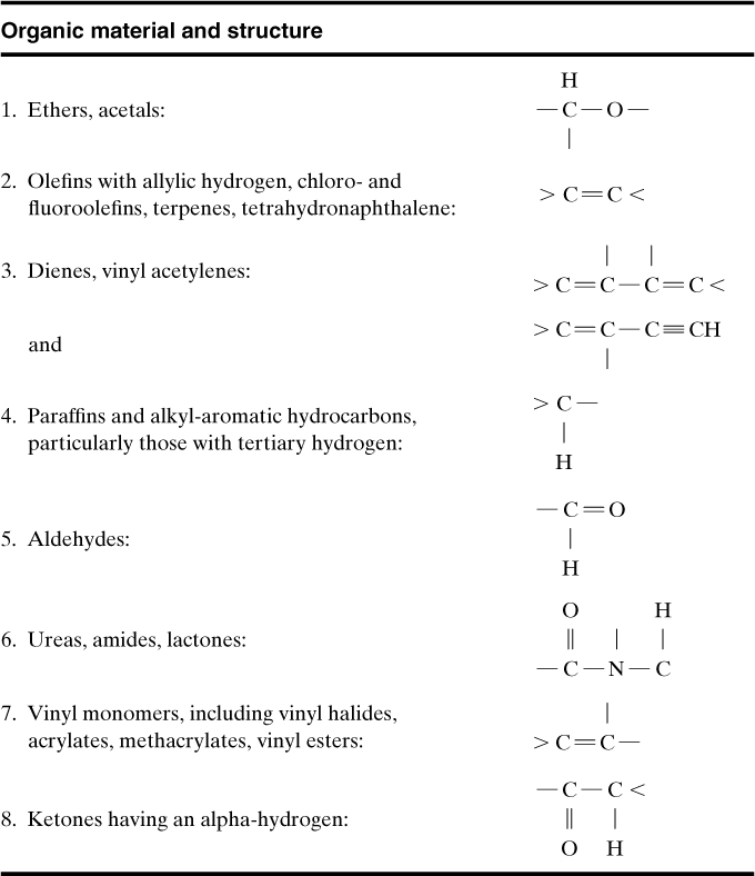
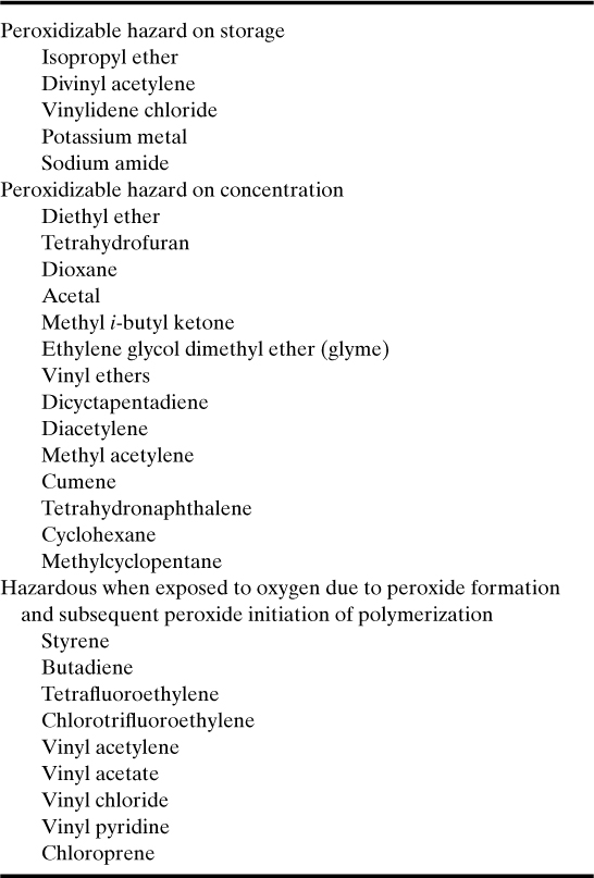
Peroxides and peroxidizable compounds are dangerous sources of explosions. Structures of peroxidizable compounds are shown in Table 14-1. Some examples of peroxidizable compounds are given in Table 14-2.
Table 14-1. Peroxidizable Compoundsa,b
a H. L. Jackson, W. B. McCormack, C. S. Rondestvedt, K. C. Smeltz, and I. E. Viele, “Control of Peroxidizable Compounds,” in Safety in the Chemical Industry, v. 3, Norman V. Steere, ed. (Easton, PA: Division of Chemical Education, American Chemical Society, 1974), pp. 114–117.
b R. J. Kelly, “Review of Safety Guidelines for Peroxidizable Organic Chemicals,” Chemical Health and Safety (Sept. Oct. 1996), pp. 28–36.
Table 14-2. Examples of Peroxidizable Compoundsa
a H. L. Jackson et al., “Control of Peroxidizable Compounds,” in Safety in the Chemical Industry, v. 3, Norman V. Steere, ed. (Easton, PA: Division of Chemical Education, American Chemical Society, 1974), pp. 114–117.
When peroxide concentrations increase to 20 ppm or greater, the solution is hazardous. Methods for detecting and controlling peroxides are outlined by H. L. Jackson et al.7
Reaction Hazard Index
D. R. Stull8 developed a rating system to establish the relative potential hazards of specific chemicals; the rating is called the reaction hazard index (RHI). The RHI is related to the maximum adiabatic temperature reached by the products of a decomposition reaction. It is defined as
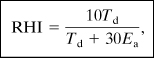
Td is the decomposition temperature (K) and
Ea is the Arrhenius activation energy (kcal/mol).
The RHI relationship (Equation 14-1) has a low value (1 to 3) for relatively low reactivities and higher values (5 to 8) for high reactivities. Some RHI data for various chemicals are provided in Table 14-3.
Table 14-3. Reaction Hazard Index Dataa
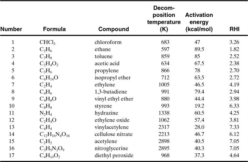
a D. R. Stull, “Linking Thermodynamics and Kinetics to Predict Real Chemical Hazards,” in Safety in the Chemical Industry, v. 3, Norman V. Steere, ed. (Easton, PA: Division of Chemical Education, American Chemical Society, 1974), pp. 106–110.
Compute the RHI for isopropyl ether, and compare the result to that shown in Table 14-3. Explain why the RHI is relatively low.
The RHI is computed using Equation 14-1:
where, from Table 14-3, Td is 712°K and Ea is 63.5 kcal/mol. The units are compatible with Equation 14-1. Substituting, we obtain
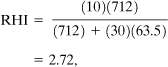
which is the same as the value given in Table 14-3. This RHI indicates a chemical with low reactivity. However, isopropyl ether is a peroxidizable compound, as indicated in Table 14-2. If we assume an RHI equivalent to diethyl peroxide (RHI = 4.64), the hazards of handling isopropyl ether are high even with peroxide concentrations as low as 20 ppm. This example illustrates the importance of understanding the chemistry of the entire system.
Bottle of Isopropyl Ether9
A chemist needed isopropyl ether. He found a pint glass bottle. He unsuccessfully tried to open the bottle over a sink. The cap appeared to be stuck tightly, so he grasped the bottle in one hand, pressed it to his stomach and twisted the cap with his other hand. Just as the cap broke loose, the bottle exploded, practically disemboweling the man and tearing off several fingers. The victim remained conscious and, in fact, coherently described how the accident happened. The man was taken to a hospital and died within 2 hr of the accident of massive internal hemorrhage.
An accident investigation identified the cause of the accident to be the rapid decomposition of peroxides, which formed in the ether while the bottle sat in storage. It is hypothesized that some of the peroxides crystallized in the threads of the cap and exploded when the cap was turned.
As ethers age, especially isopropyl ether, they form peroxides. The peroxides react further to form additional hazardous by-products, such as triacetone peroxide. These materials are unstable. Light, air, and heat accelerate the formation of peroxides.
Ethers should be stored in metal containers. Only small quantities should be purchased. Ethers should not be kept over 6 months. Containers should be labeled and dated upon receipt, and opened containers should be discarded after 3 months. All work with ethers should be done behind safety shields. Inhibitors should be used whenever possible.
Nitrobenzene Sulfonic Acid Decomposition10
A 300-gal reactor experienced a violent reaction, resulting in the tank being driven through the floor, out the wall of the building, and through the roof of an adjoining building. The reactor was designed to contain 60 gal of sulfuric acid and nitrobenzene sulfonic acid, which was known to decompose at 200°C.
The investigation indicated that the vessel contents were held for 11 hr. A steam leak into the jacket brought the temperature to about 150°C. Although previous tests indicated decomposition at 200°C, subsequent tests showed exothermic decomposition above 145°C.
The underlying cause of this accident was the lack of precise reaction decomposition data. With good data, engineers can design safeguards to absolutely prevent accidental heat-up.
Organic Oxidation11
Chemical operators were preparing for an organic oxidation. Steam was applied to the reactor jacket to heat the sulfuric acid and an organic material to a temperature of 70°C. The rate of heating was slower than normal. The two operators turned the agitator off and also shut off the steam. One operator went to find a thermometer. Approximately 1 hour later, the operator was ready to take a temperature reading through the manhole. He turned on the agitator. At this point the material in the kettle erupted through the manhole. The two operators were drenched and both died from these injuries.
The accident investigation stated that the agitator should never be turned off for this type of reaction. Without agitation, cooling is no longer efficient; so heat-up occurs. Without agitation, segregation of chemicals also occurs. When the agitator is subsequently activated, the hotter chemicals mix and react violently.
This type of problem is currently preventable through better operator training and installation of electronic safeguards to prevent operators from making this mistake. This is achieved by adding redundant and remote temperature sensors and by adding electronic interlocks to prevent the agitator from being turned off while the reaction is still exothermic.
Lessons Learned Concerning Chemical Reactivity
Case histories regarding reactive chemicals teach the importance of understanding the reactive properties of chemicals before working with them. The best source of data is the open literature. If data are not available, experimental testing is necessary. Data of special interest include decomposition temperatures, rate of reaction or activation energy, impact shock sensitivity, and flash point.
14-3. System Designs
When new plants are constructed or when modifications are needed in existing plants, detailed process designs are required. These designs must include special safety features to protect the system and operating personnel. The following case histories emphasize the importance of these special safety design features.
Ethylene Oxide Explosion12
A process storage tank contained 6500 gal of ethylene oxide. It was accidentally contaminated with ammonia. The tank ruptured and dispersed ethylene oxide into the air. A vapor cloud was formed and almost immediately exploded. It created an explosive force equivalent to 18 tons of TNT, as evidenced by the damage. The events happened so rapidly that personnel could not take appropriate cover. One person was killed and nine were injured; property losses exceeded $16.5 million.
This accident was attributed to the lack of design protection to prevent the backup of ammonia into this storage tank. It also appears that mitigation techniques were not part of the system (deluge systems, dikes, and the like).
Ethylene Explosion13
Failure of a 3/8-in compression fitting on a 1000–2500-psi ethylene line in a pipe trench resulted in a spill of 200–500 lb of ethylene. A cloud was formed and ignited, giving an explosion equivalent to 0.12–0.30 ton of TNT. This accident took place in a courtyard, giving a partially confined vapor cloud explosion. Two people were killed and 17 were injured; property loss was $6.5 million.
The probable causes of this accident include (1) use of nonwelded pipe, (2) installation of pipe in trenches, resulting in an accumulation of flammable vapors, and (3) lack of automated vapor detection analyzers and alarms.
Butadiene Explosion14
A valve on the bottom of a reactor accidentally opened because of an air failure. The spill generated a vapor cloud that was ignited 50 ft from the source. About 200 gal of butadiene spilled before ignition. Overpressures of 0.5–1 psi were estimated. Three people were killed and two were injured.
Probable causes of this accident include (1) installation of a fail-open valve instead of a fail-closed valve, (2) lack of vapor detectors, (3) lack of a block installed as a mitigating device, and (4) failure to eliminate ignition sources in this operating region.
Light Hydrocarbon Explosion15
A pipe failed and resulted in a spill of 16,800 lb of light hydrocarbons. A vapor cloud developed and ignited. The explosion knocked out the deluge systems and electrical supplies to the fire pumps. Significant damage resulted from the subsequent fires. The maximum overpressure was estimated from the damage to be 3.5 psi at 120 ft. An equivalent of 1 ton of TNT was estimated, giving an explosion yield of approximately 1% of the total energy source. This accident had two fatalities and nine injuries. The total damage was estimated to be $15.6 million.
The magnitude of this accident could have been reduced with (1) improved pipe design, (2) improved deluge system design, (3) backup or more secure electrical supply, and (4) installation of detection analyzers and block valves.
Pump Vibration16
Vibration from a bad pump bearing caused a pump seal to fail in a cumene section of a phenol acetone unit. The released flammable liquids and vapors ignited. An explosion ruptured other process pipes, adding fuel to the original fire. Damage to the plant exceeded $23 million.
This accident could have been prevented by a good inspection and maintenance program. Potential design improvements include vibration detectors, gas analyzers, block valves, and deluge systems.
Pump Failure17
Numerous accidents are unfortunate duplicates of previous accidents, as the following shows.
A pump roller bearing failure in a crude oil refinery initiated the fracture of the motor shaft and the pump bearing bracket. The pump casing then broke, releasing hot oil, which autoignited. Secondary pipe and flange failures contributed fuel to the fire. Plant damage totaled over $15 million.
Because the pump was equipped only with manually operated suction-side valves, the valves could not be reached during the fire.
Automated block valves would have minimized damage in this fire. A good inspection and maintenance program would have prevented the accident.
Second Ethylene Explosion18
A drain fitting in a high-pressure (40 kpsi) compressor line broke, allowing ethylene to escape. The ethylene cloud drifted and entered the intake system of an engine that was driving one of the compressors. The ethylene detonated in the engine, and this explosion ignited the rest of the vapors.
The explosions were felt 6 miles away. Twelve buildings were destroyed, and fire and explosion damage occurred throughout the polyethylene plant. The damage was estimated at over $15 million.
Automatic equipment promptly detected the hazardous vapor and operated the automatic high-density water-spray system, which was designed to wash the ethylene from the atmosphere. The leak was too large for the spray system to handle.
This accident could have been mitigated if the gas detection analyzers alarmed at lower concentrations. Also, in the layout design it should have been noticed that the compressor needed special consideration to eliminate this ignition source.
Third Ethylene Explosion19
Ethylene was accidentally released from a 1/8-in stainless steel instrument tubing line leading to a gauge from a main line on a compressor system. The tubing failed as a result of transverse fatigue caused by vibration from the reciprocating compressor. Ignition may have been by static electricity. This accident caused $21.8 million in damage.
The unmanned compressor building was equipped with a combustible gas detection system. However, it failed to sound an alarm because of a faulty relay in the control room. Automatic fail-safe valves functioned properly, blocking in the flow of ethylene, but not before 450–11,000 lb of gas had already escaped.
This accident emphasizes the importance of adding gas detectors that measure flammable gases at low concentrations so that alarms and block valves can be actuated before large quantities of gas are released.
Second Ethylene Oxide Explosion20
Ethylene oxide is produced by adding ethylene, oxygen, a methane diluent, and recycled carbon dioxide to a continuous reactor. Gaseous compositions are controlled carefully to keep the concentrations outside the explosion limits.
One plant experienced an emergency situation. The emergency procedures specified: Close the oxygen feed valve. The oxygen control valve was normally closed by bleeding air out of the valve bonnet diaphragm (air to open). The bleed line was opened and was noted on the control panel. The air, however, did not bleed off through the bonnet vent because a mud dauber wasp constructed mud cells over the vent hole. Although the vent valve was open, as indicated on the control panel, the air could not escape.
The gases in the ethylene oxide reactor moved into the explosive region while being above the autoignition temperature. A violent explosion occurred, resulting in several injuries and significant plant damage.
It is now an industrial standard to use positive identification of the valve position on all important safety valves—limit switches that are tripped when the valve is open or shut. In addition, all valve vent lines are now covered with bug screens to prevent blockage.
In this particular case the accident could also have been prevented with appropriate inspection and maintenance procedures.
Lessons Learned Concerning Designs
The case histories related to system design emphasize that (1) accidents occur rapidly, usually with inadequate time to manually return the system to control once the accident scenario is in progress; (2) the system designs required for preventing accidents or mitigating the consequences of accidents are frequently subtle, requiring only minor process changes; and (3) the time and effort required to develop a safe system design are justified: An engineer is hired for a fraction of the cost of most accidents.
Trevor Kletz21 and Walter B. Howard22 have emphasized the special design features for safer plants. The following recommendations also include design features from our own experiences:
• Use the appropriate materials of construction, especially when using old systems for new applications.
• Do not install pipes underground.
• Be sure that the quality of construction (for example, welds) meets the required specifications.
• Check all purchased instruments and equipment for integrity and functionality.
• Do not secure pipes too rigidly. Pipes must be free to expand so that they will not damage other parts of the system.
• Do not install liquid-filled flanges above electrical cables. A flange leak will douse the cables with liquid.
• Provide adequate supports for equipment and pipes. Do not allow spring supports to be completely compressed.
• Design doors and lids so that they cannot be opened under pressure. Add interlocks to decrease pressure before the doors can be opened. Also, add visible pressure gauges at the doors.
• Do not let pipes touch the ground.
• Remove all temporary supports after construction is completed.
• Remove all temporary startup or checkout branches, nipples, and plugs, and replace them with properly designed welded plugs.
• Do not use screwed joints and fittings when handling hazardous chemicals.
• Be sure that all tracing is covered.
• Check to ensure that all equipment is assembled correctly.
• Do not install pipes in pits, trenches, or depressions where water can accumulate.
• Do not install relief tailpipes too close to the ground where ice blockage may make them inoperable.
• Be sure that all lines that can catch water can be appropriately drained.
• When welding reinforcement pads to pipes or vessels, ensure that trapped air can escape through a vent during heating.
• Do not install traps in lines where water can collect and develop a corrosion problem.
• Install bellows carefully and according to manufacturers’ specifications. Bellows should be used cautiously. If required, inspect frequently and replace when necessary before they fail.
• Make static and dynamic analyses of pipe systems to avoid excessive stresses or excessive vibrations.
• Design systems for easy operation and easy maintenance; for example, install manual valves within easy reach of the operators, and design pipe networks for easy maintenance or with easy access to equipment requiring maintenance.
• Install bug screens on vent lines.
• Make structural analyses of relief systems to avoid structural damage during emergency reliefs.
• Safety technology must work right the first time. Usually, there is no opportunity to adjust or improve its operation.
• Critical safety instruments must have backups.
• Provide hand-operated or automatic block valves, or equivalent valves, for emergency shutdowns.
• Use electronic or mechanical level gauges, not glass sight glasses.
• Add fail-safe block valves with a positive indication of the valve position (limit switches).
Analyze the first ethylene explosion example (3/8-in fitting failure) to determine the percentage of fuel that actually exploded compared to the quantity of ethylene released in a vapor cloud.
The total energy contained in the vapor cloud is estimated by assuming the heat of combustion (Appendix B). The combustion reaction is
C2H4 + 3O2 → 2CO2 + 2H2O.
Therefore the theoretical energy is
ΔHc = 1411.2 kJ/mol = 12046 cal/g.
The tons of TNT based on this heat of combustion are calculated using Equation 6-24:
m = (500 lb)(454 g/lb) = 227000 g
ETNT = (1120 cal/g)(454 g/lb)(2000 lb/ton)
ETNT = 1.017 × 10⁹ cal/ton
Therefore
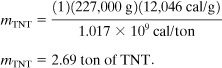
Based on the accident investigation, the explosive energy was equivalent to 0.3 ton TNT. Therefore the fraction of energy manifested in the explosion is 0.3/2.69 = 11.2%. This 11.2% is considerably higher than the 2% normally observed (see Section 6-13) for unconfined vapor cloud explosions. The higher energy conversion is a result of the explosion occurring in a partially confined area.
14-4. Procedures
An organization can develop a good safety program if it has personnel who can identify and eliminate safety problems. An even better safety program, however, is developed by implementing management systems to prevent the existence of safety problems in the first place. The management systems commonly used in industry include safety reviews, operating procedures, and maintenance procedures.
The causes of all accidents can ultimately be attributed to a lack of management systems. Case histories that especially demonstrate this problem are illustrated in this section. In the study of these case histories, one must recognize that the existence of procedures is not enough. There must also be a system of checks in place to ensure that the procedures are actually used—and used effectively.
Leak Testing a Vessel23
A 2-ft-diameter float was fabricated using stainless steel and welded seam construction. Pipefitters were given the job of checking the welds for leaks. They were instructed to use 5 psi of air pressure and a soap solution to identify the leaks.
They clamped a 100-psi air hose to a nipple on the tank. A busy instrument worker gave them a gauge. The gauge was incorrectly chosen for vacuum service and not pressure because the vacuum identifier was small.
A short time later, as the fitters were carrying out the tests, the float ruptured violently. Fortunately, there was no fragmentation of the metal, and the two fitters escaped injury.
The accident investigation found that the leak test should have been conducted with a hydraulic procedure and not air and that the vessel should have been protected with a relief device. In addition, the fitters should have taken more time to check out the gauge to ensure that it was correct for this application.
Man Working in Vessel24
Two maintenance workers were replacing part of a ribbon in a large ribbon mixer. The main switch was left energized; the mixer was stopped with one of three start-stop buttons.
As one mechanic was completing his work inside the mixer, another operator on an adjoining floor pushed, by mistake, one of the other start-stop buttons. The mixer started, killing the mechanic between the ribbon flight and the shell of the vessel.
Lock-tag-and-try procedures were developed to prevent accidents of this kind. A padlocked switch at the starter box disconnect, with the key in the mechanic’s pocket, prevents this type of accident. After the switch gear lockout, the mechanic should also verify the dead circuit by testing the push-button at all switches; this is the “try” part of the lock-tag-and-try procedure.
Vinyl Chloride Explosion25
Two vinyl chloride polymerization reactors were being operated by the same team of operators. Reactor 3 was in the cool-down and dump phase of the process, and reactor 4 was nearly full of monomer and in the polymerization phase. The foreman and three employees set to work to discharge the contents of reactor 3, but in error they opened vessel 4 instead. The gaseous vinyl chloride monomer just in the process of polymerization burst out of the vessel, filled the room, and shortly afterward exploded violently, presumably ignited by a spark from an electric motor or by static electricity generated by the escaping gas. This accident resulted in four fatalities and ten injuries in and around the plant.
The accident could have been prevented with better operating procedures and better training to make the operators appreciate the consequences of mistakes. Modern plants use interlocks or sequence controllers and other special safeguards to prevent this type of error.
Dangerous Water Expansion26
A hot oil distillation system was being prepared for operation. The temperature was gradually raised to 500°F. A valve at the bottom of the tower was opened to initiate the transfer of heavy hot oil to a process pump.
Before this particular startup, a double block valve arrangement was installed in the bottom discharge line. It was not realized, however, that the second valve created a dead space between the two block valves and that water was trapped between them.
When the bottom valve was opened, the pocket of water came in contact with the hot oil. Flashing steam surged upward through the tower. The steam created excessive pressures at the bottom of the tower, and all the trays dropped within the tower. In this case the pressure luckily did not exceed the vessel rupture pressure. Although no injuries were sustained, the tower was destroyed by this accident.
Problems similar to this are usually identified in safety reviews. This accident, for example, could have been prevented if the plant had used a safety review procedure during the design phase of this plant modification. A bleed line and possibly a nitrogen blow-out line would have prevented the accumulation of this water.
Consequences of contaminating hot and high boiling liquids with low boilers can be estimated using thermodynamics. If these scenarios are possible, relief valves should also be installed to mitigate these events, or adequate safeguards should be added to the system to prevent the specific hazard scenario.
Phenol-Formaldehyde Runaway Reaction27
A plant had a runaway reaction with a phenol-formaldehyde polymerization reaction. The result was one fatality and seven injuries and environmental damage. The runaway reaction was triggered when, contrary to standard operating procedures, all the raw materials and catalyst were charged to the reactor at once, followed by the addition of heat. The primary reason for this accident was the lack of administrative controls to ensure that the standard operating procedures were used appropriately and that the operators were trained.
The other root causes were (1) the poor understanding of the chemistry, (2) an inadequate risk analysis, and (3) no safeguard controls to prevent runaway reactions. This EPA case history also summarized seven similar accidents with phenol-formaldehyde reactions during a 10-year period (1988–1997).
Conditions and Secondary Reaction Cause Explosion28
A plant manufactured a dye by mixing and reacting two chemicals, ortho-nitrochlorobenzene (o-NCB) and 2-ethylhexylamine (2-EHA). A runaway reaction caused an explosion and flash fires that injured nine workers. The runaway reaction was the result of the following factors: (1) The reaction was started at a temperature higher than normal, (2) the steam used to initiate the reaction was left on for too long, and (3) the use of cooling water to control the reaction rate was not initiated soon enough.
The investigation team found that the reaction accelerated beyond the heat-removal capacity of the reactor. The resulting high temperature led to a secondary runaway decomposition reaction, causing an explosion that blew the hatch off the reactor and allowed the release of the contents from the vessel.
This company’s initial research for the process identified and described two exothermic chemical reactions: (1) The desired exothermic reaction is initiated at an onset temperature of 38°C, and it proceeds rapidly at 75°C; (2) an undesirable decomposition (the dye) reaction has an onset temperature of 195°C.
The operating plant was not aware of the decomposition reaction. The plant’s operating and process information described the desired exothermic reaction, but they did not include information on the undesirable decomposition reaction. Information on their MSDS was also misleading (mentioning a lower reactivity and a much lower boiling point than the actual values).
The root causes of this accident were poor operating procedures and poor process information. The operating procedure, for example, did not cover the safety consequences of deviations from the normal operating conditions, such as the possibility of a runaway reaction and the specific steps to be taken to avoid or recover from such deviations.
The recommendations from the investigation included (1) revalidating the safety data for all reactive chemicals, (2) evaluating relief requirements using the appropriate technology published by the Design Institute for Emergency Relief Systems (DIERS) (see details in Chapters 8 and 9), (3) installing the appropriate controls and safety features to safely manage these reactive chemicals, (4) revising the operating procedures and training for handling these reactive chemicals to include descriptions of the possible consequences of deviations from normal operating conditions and the steps taken to correct the resulting problems, including emergency response action, (5) implementing a program to investigate and document safety incidents, and (6) revising the MSDSs and distributing them to anyone needing this information.
Fuel-Blending Tank Explosion29
An accident occurred in a fuel-blending facility that provided a way to reuse flammable and hazardous wastes. One worker was killed and two others were injured. The explosion and resulting fire caused extensive damage to the facility.
This facility had two 1000-gal blend tanks to blend waste solvents, cleaners, and a small quantity of oxidizers, including perchlorates, nitrites, and chlorates. Before this accident the operating procedures included the following: (1) About 500 gal of solvent were added before starting the agitator; (2) no inert gas blanketing was used to lower the vapor concentration to below the LFL; (3) oxidizers were added only after the vessel was three-quarters full of solvent and the agitator was running, according to an unwritten procedure; (4) it was known that the addition of oxidizers could be hazardous if the oxidizers were added without a large quantity of liquid fuel in the blend tanks.
On the day of the accident, two workers poured four drums of liquid waste into the blending vessel—about half the amount needed to reach the agitator. Then they added solids into the top of the tank: about 2 lb each of chlorates, perchlorates, and nitrites. Thirty to 60 seconds after the oxidizers were added and while a fifth drum of solvent was being dumped into the top of the reactor, liquid suddenly erupted out of the vessel manway. The flammable vapor exploded, engulfing one employee, who died, and injuring two others.
In the EPA’s report of the investigation it was stated that strong oxidizers are generally considered incompatible with many organic substances because of the potential for dangerous reactions. Chlorates, perchlorates, and other strong oxidizers are potentially incompatible with alcohols, halogenated hydrocarbons, other organic compounds and solvents, and other flammable and combustible wastes. The potential consequences of mixing such incompatible materials are violent reactions, fires, and explosions.
The EPA’s recommendations for the prevention of this type of accident included (1) establishing standard operating procedures that are essential for safe operation, (2) evaluating the chemical and process hazards before starting a process or procedure that has been changed or modified, (3) properly training employees in the processes they work on using the standard operating procedures for the processes and job tasks, (4) ensuring that the chemicals and reaction mechanisms associated with the substances mixed or blended are well understood and documented, (5) ensuring that chemical and process hazards are understood and addressed, and (6) ensuring that all employees understand the hazards of the chemical process.
Lessons Learned Concerning Procedures
Procedures are sometimes incorrectly perceived as bureaucratic regulations that impede progress. When reviewing case histories it is apparent that safety procedures and standard operating procedures are needed to help the chemical industry (1) eliminate injury to personnel, (2) minimize incapacitating damage to facilities, and (3) maintain steady progress.
In the review of case histories relevant to procedures, additional lessons are identified:30
• Use a permit procedure for opening vessels that are normally under pressure.
• Never use gas to open plugged lines.
• Communicate operating changes to other operations that may be affected by the change.
• Train operators and maintenance personnel to understand the consequences of deviations from the norm.
• Make periodic and precise audits of procedures and equipment.
• Use procedures effectively (lock-tag-and-try, hot work, vessel entry, emergency, and the like).
• Use safety review procedures during the design phases of projects, including new installations or modifications to existing systems.
14-5. Training
Weld Failure
An oil refinery had an explosion that killed 17 people and the property damage was over $100 million. The explosion was caused by the ignition of a large cloud of propane and butane which leaked from a ruptured amine-absorber tower.
Ten years before the accident, a cylindrical section of the tower was replaced on-site. The on-site arc welding procedure was not correct. In the investigation, it was also found that the weld material was susceptible to hydrogen cracking corrosion. The leaking and falling of this tower was due to the corrosion of this weld around the entire tower.
The cause of this accident was the welding procedure, and properties of the weld material31 were not suited to the corrosive environment in the tower. The root cause was poor training: The construction engineers must know the importance of specifying construction methods and manage the process so the construction specifications are followed as required.
Safety Culture
A very large oil refinery had a series of explosions in March of 2005. There were 15 fatalities and 180 injuries. The dollar losses were also significant: $ 1.6 billion to compensate victims, an OSHA fine of $ 87 million, and a $ 50 million fine for violations of environmental regulations.
This accident was due to a major tower leak of light and heavy gasoline components that resulted in a vapor cloud explosion.32 The discharges from a relief went to a disposal system consisting of a blowdown drum with an atmospheric vent. The discharged material expelled from this vent. An inherently safer design (knockout tank and a flare system) would have prevented this accident. The major root causes identified by CSB included deficiencies with the staff management, working culture, maintenance, inspection, and safety assessments.
CSB recommended an independent panel to assess the safety culture within the company. A panel was formed and it studied the company culture; its findings are reported in the Baker Review.33. The paraphrased major results included training recommendations that are relevant to all companies. Top management must
1. Provide effective leadership and training in the area of process safety
2. Establish and implement a management system and training that continuously identify, reduce, and manage process safety risks
3. Train to develop a positive, trusting, and open process safety culture within the company
4. Train to develop an effective system to audit and improve process safety performance
Training within Universities
In December of 2007, there was an explosion of a 2450-gal reactor killing four employees, and injuring 32, including four employees and 28 members of the public who were working in companies in the plant area. The explosion damaged buildings within one-quarter mile of the facility.
The explosion occurred during the production of the 175th batch of methylcyclopentadienyl manganese tricarbonyl (never say never!). This accident was due to a loss of sufficient cooling during the process, resulting in an uncontrolled runaway reaction leading to excessive temperatures and pressures.34 The pressure burst the reactor; the reactor’s contents ignited and created an explosion equivalent to 1400 lb of TNT.
CSB found that the management (including one chemist and one chemical engineer) did not understand the runaway reaction hazards associated with producing MCMT. The major technical deficiencies were dependence on a single point temperature control system and undersized relief. They did not understand and appreciate the importance of redundant controls when controlling potential runaway reactions, nor did they have the knowledge regarding sizing reliefs for runaway reactions (two-phase flow reliefs).
CSB made training recommendations as a result of this accident:
1. The American Institute of Chemical Engineers (AIChE) and the Accreditation Board for Engineering and Technology, Inc. (ABET), should work together to add reactive hazard awareness to baccalaureate chemical engineering curricula requirements.
2. AIChE should inform all student members about the AIChE’ SACHE Process Safety Certificate Program and encourage participation.
Training Regarding the Use of Standards
Sugar Refinery. In February 2008 a series of sugar dust explosions in a sugar refining facility killed 14 workers and injured 36 who were treated for serious burns. The refinery converted sugarcane into granulated sugar. A system of conveyors and bucket elevators transported the granulated sugar to storage silos.
CSB35 found that the first (primary explosion) dust explosion was in an enclosed steel belt conveyor, and this explosion lofted and exploded sugar dust that had accumulated on the floors and elevated horizontal surfaces (secondary explosions). The secondary dust explosions propagated throughout the buildings. An overheated bearing was the most likely ignition source of the primary explosion.
The major CSB recommendations for this sugar refinery accident that were especially related to training included the following:
1. Management should train to emphasize the importance of minimizing and controlling dust hazards.
2. The company should recognize the significant hazards when handling sugar dusts.
3. Housekeeping policies and procedures should be developed and implemented through training.
Pharmaceutical Company. In January of 2003 an explosion in a pharmaceutical plant killed 6 employees and injured 38, including 2 fire fighters who responded to the accident. The explosion ignited fires throughout the facility and disabled the building’s sprinkler system. Two 7500-gal plastic tanks of mineral oil collapsed from the heat, and this fuel propagated more fires.
The CSB investigation identified the root cause of the accident as a hazard that had developed in the plant over the years;36 combustible dust from a polyethylene powder raw material had accumulated on hidden surfaces above the production area, creating the fuel for massive explosions and fires. The production product was a rubber belt, and the belt was dipped in the polyethylene-water mixture to add the polymer to the rubber belt to serve as a lubricant. Although the powder was originally in a safe water solution, the process included a belt drying step that removed the moisture and a small quantity of dry polyethylene powder. The small quantities of the dry powder, however, accumulated over time to produce the final hazard.
Because the facility produced supplies for medical use, cleanliness was a high priority, and crews continuously cleaned dust from visible areas. However, due to a poor design of the ventilation system, the dust was drawn into vents that were above a false ceiling; this was the area that accumulated the dust. The dust gradually accumulated to a thickness of about one-half inch on the ceiling tiles; as much as a ton of the powder could have accumulated. This dust was the source of the dust explosions.
The root cause of the accident was poorly trained designers and operators. The designers didn’t use the available codes and standards for handling dusts (see Chapter 13), and the operators didn’t understand the hazards of handling dusts. The facility deficiencies included (1) the use of general-purpose electrical fixtures instead of fixtures for this hazardous environment; (2) the design of the ventilation system, which allowed the accumulation of dusts on the false ceiling tiles; and (3) the lack of regular training to inform the operators and engineers about the hazards of handling dusts.
Lessons Learned Concerning Training
In 2005, CSB issued a report37 that identified 200 dust fires over a 25-year period, resulting in approximately 100 fatalities and 600 injuries. CSB stated that these disasters continue to occur because the control measures that should be in place are neglected. CSB emphasized that NFPA publishes comprehensive standards on combustible dust hazard minimization, but these standards are not recognized and understood by those needing this information. Clearly, training in this area is neglected.
When reviewing the accidents in this section, the lack of training is a major deficiency. These accidents would have been prevented by using the existing teachings of NFPA, CCPS, and others. To paraphrase Trevor Kletz: (1) We don’t invent new ways to have accidents; we continue to make the same mistakes over and over; (2) the causes of accidents are visible the day before the accident; and (3) learn from history or you’re doomed to repeat it. Winston Churchill is widely quoted as having said, “Sometimes doing your best is not good enough. Sometimes you must do what is required.” Be trained and train!!
14-6. Conclusion
This chapter on case histories is brief and does not include all the lessons relevant to accidents. The references provide excellent information for more studies. There is significant information in the open literature. However, case histories and safety literature are of no value unless they are studied, understood, and used appropriately.
Using the dangerous water expansion example, compute the approximate pressures that were developed in the bottom of this column. Assume a column diameter of 2 ft, a water slug of 1 gal, and a column pressure of 10 psia.
The areas of the column trays are 3.14 ft2. If the tray vapor paths are small openings, the worst-case scenario assumes that all the water vapor collects beneath the bottom tray. Assuming a tray spacing of 1 ft, the volume under the first tray is 3.14 ft3. Using an equation of state, we obtain
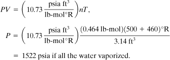
At 500°F the vapor pressure of water is 680 psia. Therefore the maximum pressure is 680 psi if some water remains as liquid water. The force on the bottom tray is
F = (680 lbf/in2)(3.14 ft2)(144 in2/ft2)
= 307,500 lbf.
If the tray is bolted to the column with six 1/2-in bolts, the stress on each bolt is
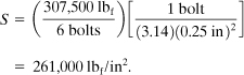
Assuming a tensile strength of 85,000 psi for stainless 316, it is clear that the trays are stressed beyond the point of failure. Evidently the vessel could handle 680 psia; otherwise it would have also ruptured.
This example explains why all the column trays were torn away from the supports and also illustrates the hazards of contaminating a hot oil with a low-boiling component.
Suggested Reading
Case Histories of Accidents in the Chemical Industry, v. 1 (Washington, DC: Manufacturing Chemists’ Association, July 1962).
Case Histories of Accidents, v. 2 (Jan. 1966).
Case Histories of Accidents, v. 3 (Apr. 1970).
T. A. Kletz, “Friendly Plants,” Chemical Engineering Progress (July 1989), pp. 8–26.
T. Kletz, Learning from Accidents, 3rd ed. (Boston: Butterworth-Heinemann, 2001).
T. A. Kletz, Plant Design for Safety (New York: Hemisphere Publishing, 1991).
T. Kletz, What Went Wrong? Case Histories of Process Plant Disasters and How They Could Have Been Avoided, 5th ed. (Boston: Butterworth-Heinemann, 2009).
S. Mannan, ed., Lees’ Loss Prevention in the Process Industries, 3rd ed. (London: Butterworth-Heinemann, 2005).
R. E. Sanders, Managing Change in Chemical Plants: Learning from Case Histories (London: Butterworth-Heinemann, 1993).
Problems
14-1. Illustrate the layered accident investigation process, using Example 14-1 as a guide, to develop the underlying causes of the duct system explosion described in Section 14-1.
14-2. Repeat Problem 14-1 for the bottle of isopropyl ether accident described in Section 14-2.
14-3. Repeat Problem 14-1 for the nitrobenzene sulfonic acid decomposition accident described in Section 14-2.
14-4. Repeat Problem 14-1 for the butadiene explosion described in Section 14-3.
14-5. Repeat Problem 14-1 for the vinyl chloride explosion described in Section 14-4.
14-6. A square stainless steel pad (5 in × 5 in × 1/8 in) is welded to a vessel that is used for high-temperature service (1200°C). The welder welds continuously around the pad, forgetting to leave an opening for a vent. Compute the pressure change between the pad and the vessel if the temperature changes from 0°C to 1200°C.
14-7. Vessels normally have a relief device to prevent damage during thermal expansion. A stainless steel cylindrical vessel has 1/4-in-thick walls and is 4 ft in diameter. It is filled with 400 gal of water, and 0.2 ft3 of air is trapped at a pressure gauge. Start at 0 psig and 50°F and then heat the vessel. At what temperature will this vessel rupture if it does not have a relief?
14-8. Compute the reaction hazard index (RHI) for nitroglycerine.
14-9. Compute the RHI for acetylene.
14-10. A hydrogen peroxide still is used to concentrate peroxide by removing water. The still is of high-purity aluminum, a material that is noncatalytic to the decomposition of peroxide vapor. The still is designed to produce 78% hydrogen peroxide. It will explode spontaneously at about 90%. Illustrate some recommended design features for this still.
14-11. A 1000-gal cylindrical vessel (4 ft in diameter) is nearly filled with water. It has a 10% pad of air at 0 psig and 70°F. If this air is completely soluble at 360°F and 154 psia, what will the vessel pressure be at 380°F? Assume a wall thickness of 1/4 in of stainless 316 and flat cylindrical heads.
14-12. An operation requires the transfer of 50 gal of toluene from a vessel to a 55-gal drum. Develop a set of operator instructions for this operation.
14-13. A reactor system is charged accidentally with benzene and chlorosulfonic acid with the agitator off. Under this condition the two highly reactive reactants form two layers in the reactor. Develop a set of operating instructions for safely handling this situation.
14-14. Develop design features to prevent the situation described in Problem 14-13.
14-15. Why are bug screens installed on control valve vents?
14-16. Read the article by W. B. Howard [Chemical Engineering Progress (Sept. 1988), p. 25]. Describe the correct and incorrect designs for installing flame arrestors.
14-17. From W. B. Howard’s article (Problem 14-16), describe his concepts concerning combustion venting and thrust forces.
14-18. After reading the article by Kelly on peroxidizables (see Table 14-2 reference), state the minimum hazardous concentrations of peroxides in solution with organic chemicals.
14-19. Using the article by Kelly (see Table 14-2), describe the commonly used peroxide detection methods.
14-20. Using the article by Kelly (see Table 14-2), describe the commonly used methods to remove peroxides.
14-21. Use the paper developed by the EPA (see footnote 27) to describe the phenol-formaldehyde runaway reactions that occurred between 1988 and 1997.
14-22. Use the paper developed by the EPA (see footnote 27) to describe the lessons learned as a result of the phenol-formaldehyde runaway reactions.
14-23. Use the paper developed by the EPA (see footnote 27) to state the EPA’s recommendations for preventing runaway reactions.
14-24. Review the case histories described in the booklet by Marsh & McLennan,38 and document the number of accidents that occurred in refineries and in petrochemical plants.
14-25. Using Marsh & McLennan, document the ten largest property damage losses in the hydrogen-chemical industries for the period 1968–1997.
14-26. Using the results of Problems 14-24 and 14-25, what specific industry has the largest losses and why?
14-27. Using the results of Marsh and McLennan, what is the loss distribution at 5-year intervals and 10-year intervals?
14-28. Using the results of Marsh and McLennan, what percentage of the major accidents are due to runaway reactions?
14-29. Using the results of Marsh and McLennan, what are the major causes of the accidents?
14-30. Review and analyze the EPA document on reactive chemicals (see footnote 29), and describe the steps required to prevent accidents of this type.