Chapter 13. Safety Procedures and Designs
Process accidents are prevented by managing the development and maintenance of important process activities. This chapter covers the details of this management process by focusing on the following topics:
• Process safety hierarchy
• Managing safety
• Best practices
• Procedures—operating
• Procedures—permits
• Procedures—safety reviews and accident investigations
• Designs for process safety
• Miscellaneous designs for fires and explosions
• Designs for runaway reactions
• Designs for handling dusts
The knowledge gained by focusing on these topics will help students, engineers, and managers prevent accidents. The motivation for including many of these topics is based on four well-known paraphrased quotations: (1) The causes of accidents are visible the day before the accident; (2) we are not inventing new ways to have accidents; (3) learn from history or you’re doomed to repeat it; and (4) sometimes doing your best is not enough—sometimes you need to do what is required.
The content of this chapter will help to identify and eliminate causes before the accident, but more important, it will help to prevent the causes in the first place. Additionally, this chapter is intended to motivate students, engineers, and managers to understand that safety is a very important subject and responsibility.
13-1. Process Safety Hierarchy
Process Safety Strategies
There are four categories of process safety strategies, in order of preference: (1) inherent, (2) passive, (3) active, and (4) procedural.1,2
• Inherent: Identify and implement ways to completely eliminate or significantly reduce hazards, rather than to develop add-on protective systems and procedures. Inherently safer design includes identifying technology that operates in less severe conditions rather than devoting extensive resources to safety systems and procedures to manage the risks associated with the hazards.
• Passive: Add safety features that do not require action by any device. Passive devices perform their intended functions without personnel or control actions. Passive systems include dikes, passive flame arrestors, and the use of welded fittings versus flanges and threaded connections.
• Active: Add safety shutdown systems to prevent accidents. Active systems include process control systems, safety interlocks, automatic shutdown systems, and automated mitigation systems.
• Procedural: Include standard operating procedures, safety rules, operator training, emergency response procedures, and management techniques in general.
Inherent and passive strategies are the most robust and reliable, but elements of all strategies are required to minimize safety problems.
Layers of Protection
The application of these safety strategies is often described as a series of layers of protection surrounding a process, as shown in Figure 12-16. These layers are necessary because it is unlikely that inherently safer design features alone will eliminate all hazards. Each layer reduces the process risk.
Active and procedural layers of protection require constant maintenance and management to ensure that they continue to function as designed. If they are not managed correctly, the protection systems will degrade and increase the hazards to an unacceptable level. Inherently safer designs make these layers of protection more reliable and robust.
13-2. Managing Safety
A simple and general description of a good management process includes deciding what needs to be done, doing it, documenting that it has been done, and studying these results and improving the process. In the area of safety, this simple process is adapted to include
• Documentation: Describe what needs to be done to eliminate hazards and accidents.
• Communication: Motivate everyone influenced by this document to do what needs to be done.
• Delegation: Delegate portions (manageable parts) of the responsibilities to those involved.
• Follow-up: Check to be sure that the documentation (procedures, etc.) is used as intended. Also use this follow-up process to make improvements.
Documentation
The safety documentation may be a procedure for conducting a safety review, designing a plant, operating procedures for normal and emergency conditions, and training procedures.
The documentation should, in general, be clear, readily available, and easy to follow.3 Additionally, the documents should be controlled; that is, the documents should include a cover page containing the revisions made, including dates and the responsible person’s signature. Notice that revisions should be expected, because the follow-up process encourages improvements.
Communications
After procedures are developed, they should not be idle documents on a shelf but should be used appropriately and enthusiastically. This communication step motivates all personnel about the documents or procedures, including the importance of the documents, the importance of everyone taking the time to use them appropriately, and the consequences of non-conformance that may seriously affect them, their coworkers, and their families. It also emphasizes the importance of preventing the existence of hazards.
Delegation
It is important to have employee participation with regard to safety responsibilities. Therefore, as many people as possible should be delegated the responsibility for developing and modifying specific documents or procedures. This participation improves the quality of the documents and it motivates compliance.
Follow-up
Responsibilities will only be completed satisfactorily if authorities follow up to check on progress. Trevor Kletz preaches, “It isn’t what you expect, but it is what you inspect.” In this safety case, the facility management must take the responsibility for inspecting. In an industrial production plant, this manager will probably be the plant manager. As stated previously, this follow-up process should also include making improvements to the documented procedures.
13-3. Best Practices
Engineers have the responsibility to use best practices when designing and operating plants. The Engineering Code of Ethics requires that their designs meet standards and established practices.4 The AIChE Code of Ethics states that engineers must perform professional services only in areas of their competence.5 Also see Table 1-1.
Some engineers neglect this responsibility with grave consequences. Many accidents investigated by CSB6 were due to the failure to use the codes, standards, and other Recognized and Generally Accepted Good Engineering Practices (RAGAGEP).
Sources of RAGAGEP include
• Government laws
• American Petroleum Institute (API) standards
• AIChE’s Center for Chemical Process Safety (CCPS) guidelines
• National Fire Protection Association (NFPA) fire codes and standards
• Methods and rules in engineering texts
• Industrial experience acquired by sharing information within industry
Some of the most widely used best practices documents include those by CCPS,7,8 NFPA,9,10 API,11 and OSHA.12
13-4. Procedures—Operating
Operating procedures are designed and managed to help operators run a plant or facility with no problems or mishaps. They should include steps for each operating phase and operating limits for the startup, shutdown, normal, temporary, and emergency procedures. The operating limits should be highlighted with the consequences of exceeding these limits, and with steps to correct or avoid deviations from normal conditions. Additionally, they should (1) contain engineering and administrative controls for preventing exposures, (2) include a description of the controls that are needed for safe operation, and (3) highlight the permits that are used to control the environment.12
13-5. Procedures—Permits
Permits are used to control nonroutine activities that are conducted in potentially hazardous environments. The permit includes a description of the hazards and actions taken to prevent accidents. The formal permit communicates relevant information between the people doing the work and the operating personnel who are affected by the work. The required permit actions include those by the workers and the operators; they include actions before the work is permitted and actions after the work is completed to transition from the permitted environment to the normal operating mode. The following examples give the key features of a few permits; but they do not include all of the requirements, because the detailed requirements may be uniquely designed for different environments.13
Hot Work Permit
This permit prevents the ignition of flammable or combustible gases or liquids in a work environment. Hot work operations include welding, grinding, torch cutting or soldering, and any other ignition sources. These permits are valid for only one shift at a time. The procedure includes the following:
1. Check for flammable materials in areas and trenches with a flammable gas detection meter. If there are flammable vapors in the area, then a permit is not allowed.
2. Remove all containers of flammable and combustible materials within a 35-foot radius of the hot work. If they can’t be removed, then cover them with a flame-retardant tarp and post the area with a fire watch.
3. Place a fire extinguisher in the area, and check to be sure that smoke detection, sprinkler, and alarm systems are working.
4. Inform operations and everyone in the area and then post the signed permit. Also, maintain a file of past permits.
Lock-Tag-Try Permit
This permit prevents injuries or damage due to the accidental release of stored energy from equipment. The stored energy includes electrical, gravitational, mechanical, and thermal. This permit is intended to prevent equipment from unexpectedly being set into motion and endangering workers. Typical activities that require this permit include an employee going into a danger zone (rotating equipment or in a vessel with an agitator), repairing electrical circuits, maintaining machinery with moving parts, cleaning jammed mechanisms, and removing guards or safety devices. The lock-tag-try procedure starts with a de-energize process:
• De-energize the equipment by unplugging electrical connections; releasing pressured lines such as hydraulic, air, steam, gas and water; and releasing spring-loaded devices.
• Lock the equipment or electrical device to prevent reactivation. A gang lock device is used to allow the device to be locked out by several maintenance trades and operations personnel.
• Tag the equipment or device to warn against re-energizing the equipment. Tags alone can be used only when the equipment cannot be physically locked, for example, some valves.
• Try to re-energize the equipment to verify that the locking process works.
Prior to going back to the normal operation, the operations supervisor is the last one to remove the lock, after being certain that the device or equipment is safe to re-energize.
Vessel Entry Permit
This permit is sometimes called the confined space permit. It is used to prevent someone from being injured in a confined space. The confined space could be a vessel, a diked area, or even reaching into a large pipe opening. The potential injuries include being overcome by a gas (nitrogen, carbon monoxide, etc.), being entangled with moving equipment, and being engulfed by entering gases or liquids. The permit includes the following steps:
1. Have an area supervisor take complete control of the vessel entry according to the permit details.
2. Isolate the equipment by disconnecting all process lines going into the vessel, which may include activating double block and bleed systems.
3. Clean the equipment.
4. Manage all other permits on this system, including lock-tag-try and hot work permits, to prevent inadvertent activation.
5. Have a second attendant in the area to help with emergencies.
6. Place emergency equipment in the area, such as a fire extinguisher.
7. Place safety cuffs around the entering person’s wrists with a chain and pulley to enable removal of the person under emergency situations.
8. Continuously monitor the oxygen concentration to be sure that it is at least 19.5%.
9. Add ventilation in the vessel or confined space to be sure the concentration of oxygen is maintained.
10. Have a ground fault interrupting light to assist the person’s visibility in the vessel.
11. Have a two-way radio at the vessel to summon help if required.
12. Use a ladder to enter the vessel, unless step-down distance is small compared to the height of the person entering.
13. Have the manager in charge sign the permit and post it in the area.
13-6. Procedures—Safety Reviews and Accident Investigations
Safety Reviews
This section expands the safety reviews described in Chapter 11, because a major focus of a review is to improve procedures and designs. In this regard, some of the features of safety reviews include the following:
1. Develop and review detailed process descriptions. This description should include (a) a process flow diagram (PFD) that contains the major equipment, pipes, and controls, and material and energy balances; (b) a piping and instrumentation diagram (P&ID) that contains all of the equipment, pipes, valves, controls, and design specifications relevant to safety; and (c) a layout to show the relationship of the equipment.
2. Accumulate and review the chemical, physical, and reactive properties of all chemicals in the plant. The list of chemicals should include all combinations of the chemicals being used in the process, and the chemicals plus possible contaminants.
3. Develop and review operating procedures, including startup, shutdown, normal, and emergency procedures. The operating procedures should highlight the limitations of the process (e.g., temperature and pressure) and give the consequences when the limitations are exceeded.
4. Accumulate and review accident investigations of previous and relevant incidents that are shared throughout the company and between companies.
5. Develop recommendations to improve the design and operating procedures to eliminate hazards and prevent accidents.
6. Develop and review the management system to ensure that all of the safety review recommendations are implemented and documented before the startup.
The plant descriptions and procedures may be adapted for specific situations; for example, laboratory descriptions will be informal sketches.
Incident Investigations
The objectives of investigations are to identify the causes of incidents, understand the interrelationship between causes, and develop actions to prevent the recurrence of similar incidents. Paraphrasing Kletz:14 “We do not invent new ways to have accidents—we only continue to make the same mistakes.” Therefore the review of accident investigations is particularly important before designing a new plant.
A typical accident investigation report format is shown in Table 13-1. This table is an adaptation of a report recommended by Kletz. As illustrated, a typical report includes recommendations that can and should be used in similar plants to prevent accidents. The Center for Chemical Process Safety also has a book covering incident investigations.15 The safety review procedure outlined above includes the review and use of accident investigations.
Table 13-1. Typical Accident Report

13-7. Designs for Process Safety
The following safe design features are only samples to illustrate some key safety features. There are many more safety designs that are described in many books and standards.16
Inherently Safer Designs
Inherently safer technology (IST) permanently eliminates and reduces hazards in order to avoid or reduce the consequences of incidents, rather than using add-on protection measures to control the risks arising from hazards. Inherent safety is a relative characteristic, and it is appropriate to describe one process as inherently safer than another. It is possible that a modification in one area may increase or decrease a hazard in another area. An engineer, therefore, should evaluate alternative inherently safer designs, in order to choose the best inherently safer design.
In these cases a decision tool is used to evaluate the options to identify the best designs. The tools include voting methods, weighted scoring methods, cost-benefit analysis, and decision analysis.17 Inherently safer technology can result in lower capital cost in new plant design and typically produces lower operating costs, greater reliability, and quicker startup times. Plants with inherently safer technologies tend to be simpler, easier and friendlier to operate, and more tolerant of errors.
Incidentally, this search for inherently safer technology applies to all stages of a process. The best opportunities for implementing inherently safer designs are in the early stages of development. But the concepts should be periodically reviewed for any process, from startup to shutdown. For example, some years ago, the CFC refrigeration technology was an inherently safer design compared to ammonia refrigeration, but the subsequent identification of the environmental ozone depletion problems required another review and IST.
Given a choice, the preferred designs are inherently safer designs. The concept of inherent safety is to design a system that fails safely even when operators make mistakes or equipment fails.18
Inherent safety is introduced in Chapter 1. A simple summary description of inherent safety includes four alternatives:
1. Moderate: Use milder conditions.
2. Substitute: Replace hazardous with nonhazardous chemicals.
3. Minimize: Use smaller vessels (reactors or storage) and quantities.
4. Simplify: Design systems to be easy to understand, including the mechanical designs and computer screens.
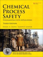
A simple design includes the mechanical configurations of vessels, pumps, pipelines, and so forth. A simple versus a complex design is illustrated in Figure 13-1. Other inherently safe designs are described in Table 1-9.
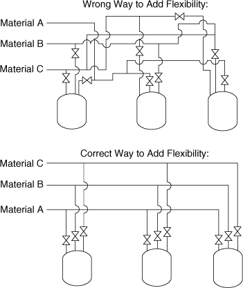
Figure 13-1. Sketch of a simple versus a complex design.
Controls—Double Block and Bleed
Double block and bleed systems are installed, for example, in monomer lines between the reactor and the monomer feed tanks as shown in Figure 13-2. This prevents the reactor contents, including catalysts, from inadvertently backing up into the monomer tank. To put this in perspective, polyether polymerization reactions require the addition of a monomer from a storage vessel at about 30 psig into a reactor. As a result of the exothermic reaction the reactor is at higher temperatures and pressures; polyether reactors are run at about 130 psig. Under this condition, if the monomer pump fails, then the reactor contents with the catalyst will back up through the pump and system into the monomer tank. This results in a catalyzed reaction with prohibitively very high monomer concentrations—a classical runaway reaction that will give high temperatures, pressures, and usually a large explosion and fire. In this case the problem is eliminated by placing this double block and bleed system in all monomer lines. When the pump fails, the double block and bleed is activated, and it is virtually impossible to transfer reactor contents to the monomer tank. Notice that the monomer lines may also include check valves, but they are not as reliable; check valves can leak through their seals.

Figure 13-2. Double block and bleed system.
Controls—Safeguards or Redundancy
Safeguards or redundant controls are a special set of controls that are added to a system to reduce the possibility of an accident. For example, a reactor that controls a rapid and exothermic reaction should have a group of safeguards to prevent the hazardous runaway as shown in Figure 13-3. Redundancy increases the reliability of a control system; the quantitative effects of redundancy are computed using fault tree analysis as discussed in Chapter 12.
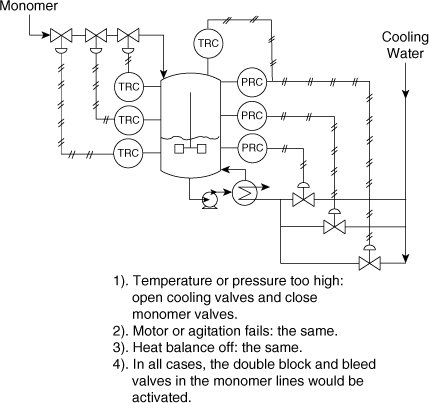
Figure 13-3. Safeguards or redundancy.
Controls—Block Valves
Block valves are installed throughout plants to shut a system down during unusual circumstances. Block valves can be manually operated or operated by a control system or field analyzer. Block valves typically are installed in lines at all vessels containing hazardous materials, and activated when an adjoining line or hose develops a leak; installed in sewer lines to prevent major leaks from contaminating a treatment facility; and sometimes installed in plants so that materials can be transferred from a hazardous environment to a safe one; for example, when a fire is around a vessel, a normally closed block valve would be opened to transfer the material to a safe location.
Controls—Explosion Suppression
As illustrated in Figure 13-4, an explosion suppression system detects a flame or pressure at the incipient phase of an explosion or fire. This detection system sets off quick-acting valves to inject a flame-quenching substance into the burning region. The one illustrated in this figure would prevent the explosion of the spray dryer. This type of system can be installed in pipelines, to prevent a fire from going from one vessel to another, and it can also be used outside equipment to detect and quench fires or explosions.

Figure 13-4. Active explosion suppression.
Flame Arrestors
As illustrated in Figure 13-5, flame arrestors are placed inline or at the end of a line. In both cases these devices quench a flame, preventing it from propagating down a pipe or duct containing a flammable. As shown in this figure, the end-of-line flame arrestor prevents a burning gas from propagating back to the vessel, if the vent gas is ignited by lightning. The inline arrestor prevents a fire or explosion from occurring in one vessel and propagating to the other vessel.

Figure 13-5. Passive flame arrestors.
Containment
With a chemical that is especially hazardous, the exits of a relief system should go to a containment system, as shown in Figure 13-6. When containment is used, however, it is very important that a detailed management system be used to ensure it is always maintained and operational. The Bhopal plant had a containment system similar to the one shown, but due to their poor management, including poor mechanical integrity, the system didn’t work when it was needed, with catastrophic results.
Figure 13-6. Relief and containment system.
An alternative is to add safeguards and redundancy to the reactor to make a relief virtually impossible. In this case the safeguard system would be designed to have an acceptable reliability; the reliability would be determined with fault tree analysis. Another alternative is to increase the MAWP of the reactor to the maximum pressure under all scenarios, that is, operating and accidental.
Materials of Construction
Material failures can occur without warning, resulting in large accidents. The way to reduce the risk of corrosion failures is to fully understand the internal and external environments, and to specify the materials of construction to withstand this environment.19 When a company has vendors constructing equipment, the company needs to monitor their construction techniques to be sure they are using the correct materials and construction standards.
To illustrate the importance of the construction standards, there was an accident in an oil refinery due to an error in the welding process; the welder used a weld material that was less noble then the tower’s material of construction. Therefore, corrosion transferred the less noble weld material to the tower. The weld seam around the entire tower failed, and the tower fell with major adverse consequences20—17 fatalities and $100 million loss.
Process Vessels
Process vessels are designed to withstand the temperatures, pressures, and corrosion environments of the process. Normally, the thickness of the vessel is chosen to withstand the pressure, and the thickness is increased for a corrosion allowance. The corrosion allowance is based on laboratory determinations of the corrosion rate and the desired life of the vessel.
The pressure necessary to produce a specific stress in a vessel depends on the thickness of the vessel, the vessel diameter, and the mechanical properties of the vessel wall.21 For cylindrical vessels with the pressure p not exceeding 0.385 times the mechanical strength of the material SM
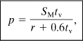
where
p is the internal gauge pressure,
SM is the strength of the material,
tv is the wall thickness of the vessel, and
r is the inside radius of the vessel.
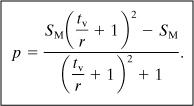
For cylindrical vessels and pressures exceeding 0.385SM, the following equation applies:
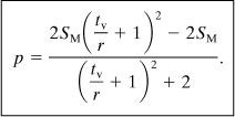
For spherical vessels with pressures not exceeding 0.665SM the equation is

For spherical vessels and pressures exceeding 0.665SM the equation is
These formulas are also used to determine the pressure required to produce elastic deformations by using yield strengths for SM. They are also used to determine the pressures required to produce failures by using tensile strengths for SM. Strength of material data are provided in Table 13-2.
Table 13-2. Strength of Materialsa
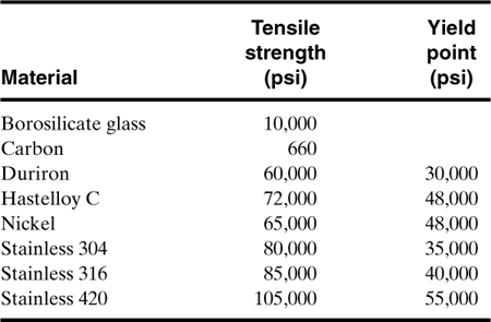
a Robert H. Perry and Cecil H. Chilton, eds., Chemical Engineers’ Handbook (New York: McGraw-Hill, 1973), pp. 6–96 and 6–97.
High-pressure failures are as likely to occur in a pipe or pipe system as in vessels. The maximum internal pressure for pipes is calculated using Equations 13-1 and 13-2.
All process vessels that are designed to withstand a pressure should also be designed for full vacuum. This vacuum constraint allows for vacuum puring and accidental process vacuums, for example, steam cleaning a vessel that is entirely blocked (no vents).
Deflagrations
Breaks in pipes or vessels resulting from deflagrations or simple overpressurizations are usually tears with lengths no longer than a few pipe diameters.
The pressure increases during deflagrations are approximately22
Detonations
As described in Chapter 6, detonations have a rapidly moving flame and/or pressure front. Detonation failures usually occur in pipelines or vessels with large length-to-diameter ratios.
In a single vessel detonations increase pressures significantly:23
When a pipe network is involved, the downstream p1 increases because of pressure piling; therefore p2 may increase by as much as another factor of 20.
Detonation failures in pipe networks are always downstream from the ignition source. They usually occur at pipe elbows or other pipe constrictions, such as valves. Blast pressures can shatter an elbow into many small fragments. A detonation in light-gauge ductwork can tear the duct along seams and can also produce a large amount of structural distortion in the torn ducts.
In pipe systems explosions can initiate as deflagrations and the flame front may accelerate to detonation speeds.
Determine the pressure required to rupture a cylindrical vessel if the vessel is stainless 316, has a radius of 3 ft, and has a wall thickness of 0.5 in.
Because the pressure is unknown, Equation 13-1 or 13-2 is used by trial and error until the correct equation is identified. Equation 13-1 is applicable for pressures below 0.385SM. Because SM (from Table 13-2) is 85,000 psi, 0.385SM = 32,700 psi, and r = 3 ft = 36 in and tv = 0.5 in. By substituting into Equation 13-1 for cylindrical vessels, we obtain
Therefore Equation 13-1 is applicable, and a pressure of 1170 psi is required to rupture this vessel.
Determine the pressure required to rupture a spherical vessel if the vessel is stainless 304, has a radius of 5 ft, and has a wall thickness of 0.75 in.
This problem is similar to Example 13-1; Equation 13-3 is applicable if the pressure is less than 0.665SM or 0.665(80,000) = 53,200 psi. Using Equation 13-3 for spherical vessels, we obtain
The pressure criterion is met for this equation. The pressure required to rupture this vessel is 1990 psi.
During an accident investigation, it is found that the source of the accident was an explosion that ruptured a 4-in-diameter stainless 316 schedule 40 pipe. It is hypothesized that a hydrogen and oxygen deflagration or a detonation was the cause of the accident. Deflagration tests in a small spherical vessel indicate a deflagration pressure of 500 psi. What pressure ruptured the pipe, and was it a deflagration or a detonation that caused this rupture?
A 4-in schedule 40 pipe has an outside diameter of 4.5 in, a wall thickness of 0.237 in, and an inside diameter of 4.026 in. From Table 13-2 the tensile strength SM for stainless 316 is 85,000 psi. Equation 13-1 for cylinders is used to compute the pressure necessary to rupture this pipe:
Equation 13-1 is applicable because the pressure is less than 0.385SM = 32,700 psi. The pressure required to rupture this pipe, therefore, is 9348 psi. Using the deflagration test data, which gave a p2 of 500 psi, and assuming pressure piling, we can estimate the deflagration pressure in the pipe using Equation 13-6:
p2 = 500 × 16 = 8000 psi.
To estimate pressures resulting from a detonation and pressure piling, we estimate the original deflagration test pressure p1 using Equation 13-6:
p1 = 500/16 = 31.3 psi.
A detonation with pressure piling is now computed using Equation 13-7:
p2 = 31.3 × 20 × 20 = 12,500 psi.
This pipe rupture was therefore due to a detonation. The next step in the investigation would include searching for a chemical reaction that would give a detonation. A small vessel could be used as a test.
An explosion rips through a chemical plant. A 1000-ft3 tank containing compressed air at 100 atm is suspected. Site damage indicates that the windows in a structure 100 yd away are shattered. Is the mechanical explosion of this compressed air tank consistent with the damage reported, or is the explosion the result of some other process?
From Equation 6-29, representing the energy contained in a compressed gas,
For air, γ = 1.4. Substituting the known quantities, we obtain
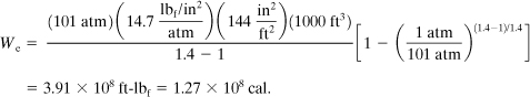
The equivalent amount of TNT is
mTNT = 1.27 × 10⁸ cal/(1120 cal/g TNT) = 1.13 × 10⁵ g TNT
= 249 lb of TNT.
From Equation 6-21 the scaling factor is
From Figure 6-23 the overpressure is estimated at 1.3 psia. From the data provided in Table 6-9 the estimated damage is consistent with the observed damage.
13-8. Miscellaneous Designs for Fires and Explosions
There are many other design features that prevent fires and explosions, as shown in Table 7-8 and CCPS books.24,25,26,27
13-9. Designs for Runaway Reactions
The essential requirements to prevent runaway reactions include
• understanding the concepts and hazards of runaway reactions (see Section 8-1),
• characterizing all possible runaway reactions in the specific system being designed (see Section 8-2), and
• using this knowledge to design the equipment and controls to avoid runaways. The equipment features may include a semi-batch reactor versus a batch, and the controls may include redundancy and double block and bleeds in the monomer feed lines (see Section 8-3).
Some of the other design features28 that are used to prevent runaways include the following:
1. Design to consume the reactants rapidly to avoid the accumulation of reactants.
2. Design the system to remove the heat and gaseous products generated by the reactions.
3. Use semi-batch reactors instead of batch and add the reactants at rates to control monomer concentrations, that is, lower concentrations that prevent excessive pressures and releases with the accidental loss of cooling.
4. Add safeguards to prevent runaways due to equipment and control failures. The equipment failures may be pumps, agitators, and so on and the control failures may be temperature and pressure controls. In cases like these, redundant control loops would catch the failure and activate a safe shutdown of the reactor system.
As mentioned above, knowledge of the potential problems with runaway reactions is essential. In addition to the key design features listed, this knowledge would help designers recognize the value of other potential problems; for example, recognizing that heat removal is more difficult with larger reactors, avoiding adding materials at temperatures above the reactor contents, and knowing that reliefs for runaway reactions need to be designed for two-phase flow.
The key design features mentioned above are for reactors, and these are sometimes called intended reactions with reactive chemicals. Runaways also occur in storage vessels, tank trucks, and tank cars; these would be classified as unintended reactions with reactive chemicals. There is a different set of design features to prevent these accidents,29 including training personnel to be sure they are aware of these potential problems; cooling the materials to safe margins below the self-accelerating decomposition temperature; including redundant controls to monitor temperatures and activate alarms; designing to separate incompatible materials; storing materials in areas remote from the process areas; and labeling reactive materials, including limiting conditions.
13-10. Designs for Handling Dusts
The safe handling of solids is important because many chemicals are produced as solids to eliminate the transportation of hazardous solvent diluents. Although engineers and chemists usually understand the hazards of flammable liquids and gases, they often don’t recognize the hazards of handling dusts. Dusts, for example, have flammability regions similar to gases, and they can burn and explode as deflagrations and detonations. The added problem with dusts, however, is that primary explosions can, and usually do, initiate secondary explosions as the explosion forces and turbulence disperse dusts that may have accumulated on floors, inducts, or above false ceilings. Dust hazards are eliminated with special design features and management practices as described below.
Flammable gases have a three-sided fire triangle that illustrates the three necessary conditions for fires; that is, to burn a flammable gas you need fuel (flammable gas) and an ignition source, and oxygen. Flammable dusts have the five-sided fire pentagon that includes fuel, an ignition source, oxygen, low moisture, and suspension in air. In this regard, dusts burn relatively slowly when ignited on a surface, but they explode when they are ignited as suspensions. Many of the design and management practices30 mentioned below are focused on this pentagon.
The essential requirements to prevent dust explosions include
• understanding the concepts and hazards of dusts (see Chapter 6),
• characterizing the properties of dusts for the specific system being designed (see Chapters 6 and 7), and
• using this knowledge to design the equipment and management practices to avoid dust explosions; see the next two sections.
Designs for Preventing Dust Explosions
Some of the key design features31 that are used to prevent dust explosions include the following:
1. When transferring dusts to flammable liquids, use containment and inerting as described in Chapter 7.
2. Eliminate ignition sources due to tramp metal, mechanical failure, overheating, electrical sparks, high dust concentrations, and static electricity. The tramp metal problem is solved by adding magnetic traps that collect metal parts; the mechanical failure problems are solved by adding detectors to detect failures and initiate a safe shutown; overheating problems are solved by monitoring the temperature of bearings and belts (e.g., slipping); electrical sparks are eliminated by using all explosion-proof electrical fittings (Class III and appropriate division; see Chapter 7); the high dust concentrations in equipment and in vents from equipment are reduced by using pneumatic dust collection systems (sometimes called bag houses), and high dust concentrations outside of equipment due to leaks from flanges or equivalent are prevented by adding gaskets and tightening the gasket flanges; and static electricity problems are solved using the teachings of Chapter 7, including grounding and bonding.
3. Mitigate dust explosions using vent panels and explosion suppression as described in Chapter 7.
Management Practices for Preventing Dust Explosions
There are two especially important management practices that should be used to prevent dust explosions: (1) schedule periodic cleaning to remove accumulated dusts from floors, ducts, and even above false ceilings (see Chapter 14), and (2) control welding and cutting operations using the hot work permits discussed previously. Additional recommended practices include scheduling the periodic cleaning of the magnetic tramp metal traps and mechanical integrity checks to be sure all controls and alarms are working as specified.
Suggested Reading
API 750, Management of Process Hazards (Washington DC: American Petroleum Institute, 1990).
L. Britton, Avoiding Static Ignition Hazards in Chemical Operations (New York: American Institute of Chemical Engineers, Center for Chemical Process Safety, 1999).
Center for Chemical Process Safety, Guidelines for Design Solutions for Process Equipment Failures (New York: American Institute of Chemical Engineers, 1998).
Center for Chemical Process Safety, Guidelines for Engineering Design for Process Safety (New York: American Institute of Chemical Engineers, 1993).
Code of Federal Regulations, “Process Safety Management of Highly Hazardous Chemicals,” 29CFR 1910.119 (57FR23061), June 1, 1992.
R. K. Eckhoff, Dust Explosion in the Process Industries, 3rd ed. (Houston: Gulf Publishing, 2003)
M. Glor, Electrostatic Hazards in Powder Handling (New York: John Wiley & Sons, 1988).
Trevor Kletz, Plant Design for Safety: A User-Friendly Approach (New York: Hemisphere Publishing Corporation, 1990).
T. Kletz, Process Plants: A Handbook for Inherently Safer Design, 2nd ed. (New York: Taylor & Francis Group, 2010).
J. F. Louvar, B. Maurer, G. W. Boicourt, “Fundamentals of Static Electricity,” Chem. Engr. Prog. (Nov. 1994), pp. 75–81.
Problems
13-1. Determine the pressure required for a pipe to swell and the pressure required for a pipe failure. The pipe is 3-in stainless 316 schedule 40 pipeline for transporting a gas mixture that is sometimes within the explosive composition range.
13-2. Determine the required thickness of a reactor with cylindrical walls that must be designed to safely contain a deflagration (hydrocarbon plus air). The vessel has a diameter of 4 ft and is constructed with stainless steel 304. The normal operating pressure is 2 atm.
13-3. An accident occurs that ruptures a high-pressure spherical vessel. The vessel is 1.5 ft in diameter, is made of stainless 304, and the walls are 0.25 in thick. Determine the pressure required to cause this failure. Develop some hypotheses regarding the causes of this accident.
13-4. Compute the theoretical maximum pressure obtained after igniting a stoichiometric quantity of methane and oxygen in a spherical vessel that is 1.5 ft in diameter. Assume an initial pressure of 1 atm.
13-5. Compute the theoretical maximum pressure obtained after igniting a stoichiometric quantity of methane and air in a spherical vessel that is 1.5 ft in diameter. Assume that the initial pressure is 1 atm.
13-6. Using the results of Problem 13-4, determine the required vessel wall thickness to contain this explosion if the vessel is made of stainless 316.
13-7. Using the results of Problem 13-6, determine the vessel wall thickness required to contain an explosion in another vessel that is physically connected to the first vessel with a 1-in pipe. Describe why the second vessel requires a greater wall thickness.
13-8. Describe why accident investigation recommendations must include recommendations to improve the management system.
13-9. Describe a preventive maintenance program that is designed to prevent automobile accidents.
13-10. Describe the concept of using block valves to prevent detonation accidents in a system handling flammable gases. The system has two vessels that are connected with a 4-in vapor line.
13-11. Using the data and results of Example 13-3, determine the wall thickness required to eliminate future failures. Assume that the vessel’s cylindrical wall height is equal to the vessel’s diameter.
13-12. Determine the vessel wall thickness required to contain an explosion of 2 lb of TNT. The spherical vessel is 1.5 ft in diameter and is constructed with stainless steel 316.
13-13. In the 1930s there were many accidents in homes because of the explosion of hot water heaters. Describe what features are added to water heaters to eliminate accidents.
13-14. Develop a definition for a major incident, and compare it to CCPS’s definition. See CCPS, Plant Guidelines for Technical Management of Chemical Process Safety (1992, p. 236).
13-15. A management system for accident investigations includes good communications. What are the tangible benefits of a good communications system? Compare your answer to CCPS’s (1992, p. 238).
13-16. Near-miss (close-call) accident investigation reports are also important. Define near-miss accidents. Compare your answer to CCPS’s (1992, p. 239).
13-17. What facts should a near-miss accident report include? Compare your answer to CCPS’s (1992, p. 240).
13-18. The U.S. Chemical Safety and Hazard Investigation Board investigated an accident at the Morton Specialty Chemical Company in 1998. Evaluate the board’s recommendations, and break them down into three layers of recommendations. See www.chemsafety.gov/.
13-19. An accident investigation at the Tosco Refinery Company emphasized the importance of a management system. Describe the accident, and develop three layers of recommendations. See www.chemsafety.gov/.
13-20. An EPA-OSHA accident investigation at Napp Technologies, Inc., in Lodi, New Jersey, developed the root causes and recommendations to address the root causes. Describe the accident, and develop layered recommendations for this specific accident. See www.epa.gov/ceppo/pubs/lodiintr.htm.
13-21. The accident investigation at Lodi, New Jersey, included previous industrial accidents with sodium hydrosulfite and aluminum. Summarize the findings of these accidents and develop a few management system recommendations for these industries. See www.epa.gov/ceppo/pubs/lodirecc.htm.
13-22. The double block and bleed system shown in Figure 13-2 bleeds chemicals into a small vessel. This method, however, creates a new hazard: It adds another vessel that contains a hazardous chemical. Design an inherently safer system.
13-23. It is recommended that process vessels be designed for full vacuum. Describe several ways to cave in vessels that are not designed for full vacuum.
13-24. Redundant instrumentation is an important design concept for improving the safety of a system. Give examples where redundant instrumentation would have prevented major accidents.
13-25. The concept of using checklists is very important. Give several examples of useful checklists.
13-26. A process description should include a summary to highlight major safety issues. Describe the concept of this summary.
13-27. Develop a few examples of inherently safe designs.
13-28. Metal sheathing on the outside of insulated pipe is known to accumulate static charges. What two methods are used to prevent this hazard and which is better?
13-29. Design a system for pouring a powder into a flammable liquid.
13-30. Nitrogen is used most frequently to inert systems; that is, nitrogen is added to keep the flammable vapor concentration below the LFL. What precautions are taken when handling nitrogen?