The solderless — introduced in Chapter 1 — is a quick and easy way to experiment with low-power electronic circuits. Learning how to make use of a breadboard will save you countless hours of "workbench time" as you experiment and develop your own circuits and projects. In this chapter, you build a pair of simple circuits to get you familiar with using a breadboard.
Before you begin building a circuit on a solderless breadboard, there are a few simple techniques to keep in mind to minimize trouble:
Keep connections short. As purchased, the leads of components such as resistors and capacitors are so long that the component is often left sticking up in the air above the breadboard once the leads are inserted into the contacts. In a densely-packed circuit, this allows the leads to flop around and short out adjacent components. A forest of leads also makes it difficult to see what is connected to what. If your circuit will have a lot of components, trim the leads so the components are close to — but not jammed against — the breadboard. The same goes for jumpers — keep them near the breadboard and bend them into shapes that make it easy to see where they're connected. It's easier to keep things organized if you keep a good selection of wire lengths handy.
Don't make those connections TOO short. When stripping insulation off the jumpers, leave enough wire exposed so that when they're fully inserted, you can see some wire going into the hole of the plastic strip. If there isn't enough bare wire, it might look like the wire is connected when it really isn't. For component leads, make sure the lead can be fully inserted into the contact and firmly gripped. If you cut the lead too short, the component can easily pop out of the hole and not make contact.
Use color to your advantage. Maybe you got a good deal on a zillion feet of wire with black insulation, but don't use it for every connection. You'd go crazy trying to keep track of the connections, and troubleshooting would be much more difficult than if you make consistent use of several colors. Any color convention will work, as long as you use it consistently. For example, surplus or used telephone home-wiring cable with four solid wires (the stiff, round cable, not the flat, flexible "modular" cable) is a great source of suitable (and cheap) wire that comes with a great color code built in, as follows:
Black for ground
Red for power supplies
Yellow for control connections
Green for signals or data
Track your progress. For circuits with more than one complex integrated circuit (IC) or more than a dozen components, keep track of what you've wired up. Make a copy of the schematic diagram and as you connect each wire or lead, use a highlighter or colored pencil to trace the connection on the schematic. This is a good way to avoid missing a connection.
Make test points. Use short pieces of bare wire to make convenient test points for measurements or for connecting to external cables. By providing dedicated connection points, you avoid having test leads pull component leads out of contacts, accidentally short out, or slip off an IC pin.
Ready to start building? Let's get going!
An audio amplifier is a very useful circuit and a good one for breadboard-building practice. This particular circuit uses an integrated circuit (IC) and several resistors and capacitors. If you pay attention to which pin is which on the IC — and double-check your wiring — chances are excellent that it will work properly the first time power is applied!
Note
IC: Integrated circuit, also known as a chip. A collection of components, usually transistors, in a single package with multiple leads. Common examples of ICs include sets of digital logic gates, amplifiers, timers, and microprocessors.
Figure 3-1 shows the schematic of the amplifier circuit. (If you need help understanding schematics, refer to Chapter 2 of this book. The integrated circuit, IC1, is a type of amplifier called an op-amp (short for operational amplifier) because these amplifiers were originally used in analog computers to perform mathematical operations. The type of op-amp used here is Model 741.
The numbers surrounding the symbol are the pin numbers of the most common plastic DIP (dual in-line package) form of the 741. Pins 1 and 5 are left unconnected (nc for not connected). The signal flow is left to right from the input (VIN) to the output (VOUT). A single-polarity 12V DC power supply is assumed to be used, with the chassis ground symbol representing the ground or DC return terminal of the supply (also referred to as the negative terminal, even though the voltage is not negative with respect to ground). A battery or battery pack that can supply approximately 12 volts can also be used to power the circuit.
Note
DIP: Dual In-line Package. The physical form of an IC that has a rectangular plastic body with one row of leads on each side in a line. DIP packages range from 6 to 64 leads.
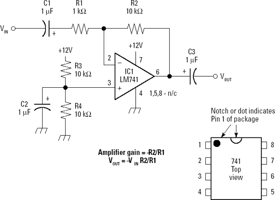
Referring to the schematic in Figure 3-1, you can see the op-amp wired so current from the input (through C1 and R1) is balanced by an equal and opposite current through R2. (No current is allowed to flow into pin 2.) The voltage at pin 2 of the opamp stays at the same voltage as pin 3. That's because R3 and R4 form a voltage divider (a resistor circuit whose output is a fraction of the applied voltage); they keep the DC voltage at pin 3 steady at 6V, which is about one half the power-supply voltage (see http://en.wikipedia.org/wiki/Voltage_divider for more). To balance the input current, the op-amp's output voltage must change to make the difference in voltage between pin 2 and pin 6 cause a balancing current to flow in R2.
If R1 and R2 are the same value, the output pin of the op-amp only has to have an equal-and-opposite voltage to VIN. That means the gain of the amplifer — the factor by which the input signal is amplified — is −1. This is called an inverting amplifier.
If R1 and R2 have different values, then the op-amp has to swing more (if R2 > R1) or less (if R2 < R1) than the input. The gain of the amplifier circuit, AV, is then the ratio of R2 to R1, multiplied by −1 because of the equal-but-opposite balancing rule:
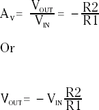
Since R1 = 1kΩ and R2 = 10kΩ, AV = −10
The function of capacitors C1 and C3 in the circuit is to block the DC voltage that will be present at pins 2 and 6 because a single supply polarity (+12V) is used. R3 and R4 cause the value of the output, pin 6, to be 6V when no input audio signal is applied. This is called bias and the 6V resting value is the quiescent value of output voltage. C2 filters the voltage at pin 3 and makes sure it remains a steady DC value by shunting any AC signal present to ground.
Solderless breadboards are very well suited to building digital circuits — those that use discrete voltage levels as signals representing logic values of TRUE and FALSE. With the amazing functionality of today's integrated circuits, even a small breadboard can be used to construct a sophisticated circuit.
To illustrate how to build digital circuits on a breadboard, we'll construct a digital timer circuit based on the MC14536B IC. This flexible IC consists of an oscillator (a circuit that generates a continuous stream of pulses), 24 flip-flops (circuits that divide the frequency of a stream of pulses by two), and some control inputs that configure or set up the IC to act in different ways. We are going to configure the control inputs so the IC counts a selectable number of pulses, turns on an LED (light-emitting diode), and then stops.
Figure 3-2 shows the schematic for the digital timer circuit. The positive power supply voltage (+12V) is connected to the IC's power pin and several of the control signal lines and components at the top of the page. Ground is at the bottom, connected to the IC's ground pin and other IC inputs and components. Control inputs to the IC are shown on the left of the IC symbol and the output from the circuit is shown on the lower right.
Note
Timer: In the world of digital circuits, a timer is any circuit that counts a fixed number of pulses before taking some action.

Figure 3-2. The schematic for the digital timer shows the IC in the middle with control inputs on the left and the output in the lower right-hand corner.
Tip
Why not draw a digital schematic with the pins organized around the ICs in the same order as the physical device? For the IC in the current circuit, that would place pin 1 in the upper left, pin 8 in the lower left, and so forth. While that the resulting schematic might have a stronger resemblance to the physical layout of the circuit, the circuit's functions would be obscured as the signal lines crossed each other and made numerous bends. Grouping signals and pins of like functions together makes the schematic and circuit much easier to understand.
Before I explain how the circuit works, download the IC's data sheet (as described in the tip at the start of this task). There is a lot of detailed engineering information you can just skip over as I explain how the timer works. Remember that if a 1 appears in the data sheet's truth tables and circuit descriptions, it means that a pin is connected to +12V (or puts out that voltage); a 0 means the pin is connected to ground or outputs a voltage close to 0V.
The basic function of the timer as we've configured it is to wait for a certain period by counting a fixed number of pulses and then turn on the LED. (the data sheet shows this schematic as "Time Interval Configuration Using the On-Chip Oscillator") Counting begins when the RESET signal (pin 2) is grounded (which happens when you close switch SW1). When the required number of pulses have been counted, the timer turns on the LED and stops counting. Opening the switch returns RESET to +12V (a logic 1) and that resets the timer. Closing the switch starts the cycle again.
The timer's oscillator circuit generates the pulses with a frequency determined by the value of C1 and R3 according to the formula:
Frequency in Hertz = 1 / (2.3 * C1 * R3)
The pulses are applied to a string of 24 consecutive flip-flops. Each flip-flop divides its input frequency by two, so the frequency gets lower and lower with each successive division. By the time the pulses have progressed all the way to flip-flip #24, the frequency of the pulses from the oscillator has been divided by 224 or 1,677,216. If the frequency of the oscillator was 1,677,216 Hz (pulses per second), the output of flipflop #24 would be 1 Hz (pulse per second).
Control signals A, B, C, and D (pins 9 through 12) select which one of the 24 flip-flop output signals is connected to the Decode Output (pin 13). Only one can be connected at a time. The data sheet's truth tables show the flip-flop output selected by each combination. Use the truth table with 0's in the column labeled "8-BYPASS"; that's because in our circuit, the 8-BYPASS pin (pin 6, connected to ground) is a 0. The schematic in Figure 3-2 shows ABCD equal to 1100 and that selects stage 12. The higher the number of the stage connected, the longer the time period from switch closing until the LED comes on.
The values for C1 and R3 result in an oscillator pulse frequency of approximately 4350 Hz. The first flip-flop output that can be selected (with ABCD = 0000) is flip-flop #9. Its output has been divided by 2 nine times or by 29, a division of 512. That frequency is 4350/512 = 8.5 Hz. So if I grounded A, B, C, and D — and then closed the switch — the LED would come on 1/8.5 = 0.12 second later. That's pretty fast!
By changing the connection of the ABCD inputs from 0 to 1 in various combinations, flip-flop outputs farther down the line will be selected. Selecting flip-flop output #12 (ABCD = 1100) results in a division by 212 = 4096 or 1.06 Hz and the LED would wait for 0.94 seconds before coming on after the switch is closed. If ABCD were set to 1111 (all four connected to +12V) for the maximum division of 224, the output frequency would be a measly 0.004 Hz — you'd have to wait 241 seconds to see the LED come on after the switch was closed!
This section is a sequence of steps to get you from a handful of parts and an unpopulated breadboard to a working circuit ready for testing. Be sure you understand the instructions completely before starting each step. (Refer to the tools and techniques in Chapters 1 and 2 if you're unclear.) Don't forget to make a copy of the schematic for keeping track of your progress, as described at the beginning of this chapter.
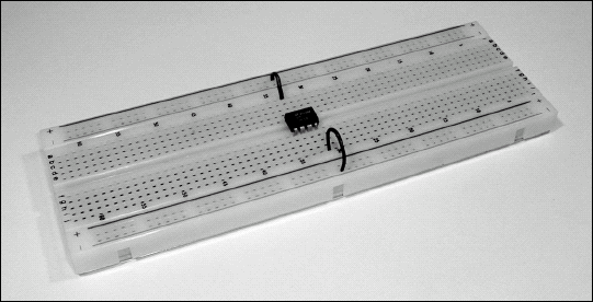
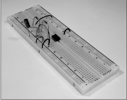
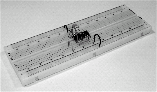
Insert the leads (the wire pins coming out of the IC) of the LM741 op-amp IC into the breadboard, roughly in the middle of the plastic strip, straddling the center slot with each lead in a separate row of holes. Be sure that none of the eight leads are bent under the plastic package. Also be sure that two of the leads did not get stuffed into the same hole. (A magnifying-glass inspection is a good idea while you're learning.) Identify pin 1 of the IC.
Decide which of the breadboard rails will be +12V and which will be ground. Install a short jumper between pin 7 of the IC and the +12V rail. Install another short jumper between pin 4 of the IC and the ground rail. Mark off these power connections on the schematic by tracing them with a highlighter or colored pencil.
Trim the leads on R3 and R4 to about 1 inch long, and then bend about half of each remaining lead at a right angle in the same direction so that the resistor looks like a "U" (as shown in Step 2's figure). Create the voltage divider by installing R3 and R4 near the IC so one lead from each resistor is in the same row of holes (connected together) and the remaining leads are in different rows of holes as shown in the Step 4 figure.

Add a jumper from the open lead of R3 (the one in a row all by itself) to the +12V rail. Then add another jumper from the open lead of R4 to the ground rail. Mark off both resistors, and then the power and ground connections, on the schematic. Don't mark off the line going to pin 3 of the IC or the connection to C2 — you haven't done those yet!
Complete the voltage divider with a jumper from the connection of R3 and R4 to pin 3 of the IC. Take a close look at C2 and carefully identify which lead is positive. Connect the positive lead of the capacitor to the connection between R3 and R4. Connect the negative lead of C2 to the ground rail or to an unused row of holes and add a jumper from there to the ground rail. Mark off both C2 connections and the connection from the divider to pin 3 of the IC. (Remember to track your progress on the schematic from here on out — good luck!)

Bend the leads of gain-control resistor R2 so it can be connected directly between the rows of holes connected to pin 6 of the IC and pin 2 of the IC. It may stick up in the air a little bit, but that's okay since there aren't any other components around it. Connect one lead of the other gain-control resistor R1 to the row of holes connecting R2 and pin 2 of the IC. The remaining lead of R1 should be inserted in an unused row of holes nearby.
Tip
Electrolytic capacitors usually identify the negative lead with a minus sign in a round circle or an arrow pointing to the lead. Some may have a plus sign near the positive lead.
Note
From here on, connect means "put a component lead into a hole" — got it? You bet!
After carefully identifying the positive lead of each capacitor, connect C1 from the open lead of R1 to an unused row of holes nearby. Connect C3 from the connection between R2 and pin 6 of the IC to another unused row of holes.
Create connection and test points by taking a ¾-to-1-inch piece of bare wire, making a small loop at one end, and inserting the straight end into the same row of holes as the open lead of C1. This is the input-signal connection. Do the same at the open lead of C3. This is the output-signal connection. Add two more test points on the ground and +12V rails. These are the ground connections for input and output signals. The small loops make good connection points for a test probe or clip.
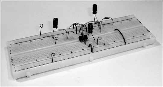
Congratulations! You just built an amplifier circuit! All the lines on the schematic should now be colored, signifying that all connections are complete. Before applying voltage, carefully inspect the circuit (use your magnifier) to ensure that all connections are where you thought they were — and that all components and jumpers are fully inserted into their contacts. Be sure that none of the component leads are leaning against other leads.
Warning
If the capacitors are connected backwards with the negative lead more positive than the positive lead, they may be damaged when power is applied. When this happens, you may smell something pungent, the capacitor will probably get warm or even hot, it may emit what looks like smoke or fumes, and on occasion may give off a loud SNAP! This isn't a catastrophe — you just received an inexpensive lesson on what a bad electrolytic capacitor smells, looks, and sounds like! Nevertheless, use pliers to lift the afflicted component from the board and toss it in the garbage can. Wipe off any deposit from the breadboard and replace the capacitor, getting the polarity right this time.
You've double-checked the circuit against the schematic. You're sure the IC and the capacitors are all installed with the correct orientation of their leads. You're ready to apply the juice and give it the smoke test electronic shop-talk for a circuit's first application of power.
The following steps assume that you have used a voltmeter before. If you're unfamiliar with how to use a voltmeter or connect a signal source to a circuit, refer to Part IV "Measuring and Testing" first.
If you have an adjustable power supply, be sure its output voltage is set to +12V.
Connect the rails to the power supply or battery pack terminals using clip leads or suitable wires.
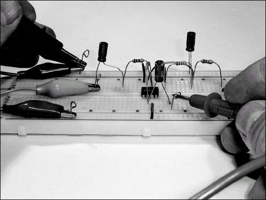
Set your meter to read DC volts. Connect its negative probe to the ground test point, either with a clip lead or by using the probe itself (you may have to hold it in place). Connect the positive meter lead to the +12V test point.
It's time to switch on the power supply. Your meter should read +12V. If not, turn the power supply off immediately and correct any wiring problems. If it reads 0, one of the power supply connections is open or a connection to one of the rails is faulty or what you thought was a rail isn't a rail. Figure out which is which and try again. If the meter read −12V, the power supply or rail connections are backward. The IC is probably damaged if it is hot or even warm and may have to be replaced.

If the meter reads +12V, move the positive probe to pin 3 of the IC or any lead connected to pin 3 of the IC. It should read +6V. Pin 6 of the IC should also read +6V. If not, check the voltage divider wiring. There should be +6V at the connection between R3 and R4 and at pin 3 of the IC.
To apply AC voltage, set the output of your AC signal source (a signal or function generator or even a music player) somewhere between 0.1V and 0.5V when measured with a voltmeter set to read AC volts. (The exact level isn't critical.) Connect the ground lead of the audio source to the ground-rail connection point, and the hot lead of the audio source to the input-signal connection point. (If you need help making an audio cable or identifying connector wiring, Part III is the place to go for more information.)
Measure the output voltage by connecting the voltmeter to the output-signal connection point. The voltage here should be approximately 10 times the voltage at the input. If you have a pair of headphones or a speaker, connect it with clip leads to the amplifier output.
Don't stop now! Try some different resistor values for R1 and R2 to see what happens to the circuit gain. For example, swapping R1 and R2 (turn the power off first) will turn the gain from ×-10 to ×-one-tenth; the output will get smaller. Change R2 to 1 kΩ will make the gain equal to unity (same level in and out). With the output at a comfortable listening level, reduce the power-supply voltage if it is adjustable until the output signal begins to distort. Why does it distort? Because the amplifier output is being driven to the limit of the power supply voltage and can't increase any further — this is called flattopping or clipping.
Note
Flattopping or clipping: When the input signal to an amplifier is too large for it to be reproduced, the circuit output voltage can not increase beyond the power supply voltage. If the output signal is observed with an oscilloscope, the portions of the signal that are too large to amplify are flat, straight lines and the waveform looks like its top has been "clipped off."
As in the previous task, this section is a sequence of steps to get you from a handful of parts and an unpopulated breadboard to a working circuit ready for testing. Be sure you understand the instructions completely before starting each step. Refer to the tools and techniques in Chapters 1 and 2 if you're unclear. Don't forget to make a copy of the schematic for keeping track of your progress as described at the beginning of this chapter!
Download the manufacturer's information for the IC (called a data sheet) by entering the IC part number and "data sheet" into an Internet search engine. I found the data sheet for the MC14536B at www.onsemi.com/pub/Collateral/MC14536B-D.PDF. The data sheets for many ICs and transistors can be found just as easily.
The MC14536B IC is sensitive to static. If you live in a dry climate (the kind in which you can generate a spark by walking across the carpet), you should take precautions to be sure you don't zap your IC by accident. Static dissipation mats are available from most electronic vendors, but an inexpensive substitute is to tape a strip of aluminum foil to the front of your workbench. Ground the strip by connecting it to a 10 kΩ resistor, using clip leads or wire taped to the aluminum foil. Connect the other lead of the resistor to the negative terminal of your power supply or battery pack. As you work on the circuit — and every time you approach the bench — be sure to touch the foil to discharge the static charge carried by your body before touching any circuitry.
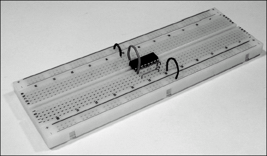
Insert the leads of the MC14536 IC into the breadboard, roughly in the middle of the plastic strip, straddling the center slot with each lead in a separate row of holes. Be sure that none of the 16 leads are bent under the plastic package. Also be sure that two of the leads do not get stuffed in the same hole. Use a magnifying glass to take a close look. Identify pin 1 of the IC.
Decide which of the breadboard rails will be +12V and which will be ground. Install a short jumper between pin 16 of the IC and the +12V rail. Install another short jumper between pin 8 of the IC and the ground rail. Mark off these power connections on the schematic by tracing them with highlighter or colored pencil.

Note that several of the control-signal pins (1, 6, 7, and 15) are connected to ground. Use short wires to connect all these pins together. Use one more short wire to connect pins 7 and 8, grounding them all. Remember to mark off those connections on your schematic — and do so at every step.
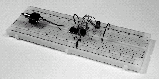
Wire the oscillator section by connecting one lead of R2 to pin 3. Connect one lead of C1 to pin 4. Connect one lead of R3 to pin 5. The remaining leads of these components should all be connected together by plugging them into an unused row of holes near the IC.
Wire the output section by connecting pins 13 and 14 together with a short wire. Connect one lead of R4 to pin 13. Connect the remaining lead of R4 to the anode lead of light-emitting diode (LED) D1. Connect the cathode lead of D1 to the ground rail.

Tip
If you are unsure which lead of D1 is the anode, the packages in which LEDs are sold often feature a drawing showing the anode and cathode — and a round LED package usually has a flat side identifying the cathode lead. You can also test the diode with your multimeter set to measure resistance through the diode. With the meter showing some resistance (instead of an open circuit), the lead connected to the meter's positive (+) terminal is also connected to the LED's anode lead.
Connect the RESET switch pins to unused rows of connections. The pins of most miniature toggle switches cannot be directly inserted into breadboard contact holes — they are too big. Solder short pieces of bare wire to the switch pins to make breadboard-compatible pins.
Connect one of the switch's pins to ground and the other pin to pin 2 of the IC. (If your switch has three pins instead of two, use your multimeter to find the pair of pins on the switch that open and close when you move the switch handle from one position to another. Make a note of which position of the handle closes the contacts between that pair of pins; the timer will run with the switch in that position. Leave the third pin unconnected.) Connect one lead of R1 to pin 2 of the IC and the other lead to pin 16 of the IC.
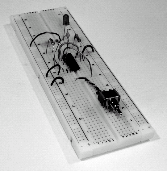

Wire the control signals A, B, C, and D as shown. Pins 9 and 10 should be connected to +12V and pins 11 and 12 to ground.
Make sure your power supply is set to +12V, open switch SW1, and apply power to the breadboard's +12V and ground rails. Use your multimeter to check the voltage between pin 16 and pin 8 — it should be +12 volts. Check each pin to see that it has the correct voltage; +12V or ground, according to the schematic. The clock-circuit pins (3, 4, and 5) will have some intermediate voltages — and that's fine.
Close the switch and verify that the LED comes on about 1 second afterward. The actual time may be anywhere from a half second to several seconds. The important thing is that the timer counts pulses and then turns on the LED.
Experiment with different combinations of A, B, C, and D to see what happens as you set the timer to different periods. (See the section "How a Digital Timer Works" earlier in this chapter.)
Note
If your circuit doesn't work, go back over the schematic very carefully and double-check your wiring. Make sure leads are inserted into the holes you thought they were. Sometimes it helps to have a friend who hasn't worked on the circuit compare it to the schematic independently. Digital circuits generally work if connected properly, so the likely problem is a wiring error.