
The mechanical part of electronic construction is usually quite straightforward. Circuits and their operating controls and connectors need to be mounted in a protective enclosure or housing and the circuits themselves need to be constructed properly. In this chapter, you'll be introduced to the basics of working on enclosures and panels made of sheet metal and plastic.
Soldering is a fundamental skill to the electronic technician. If you've never soldered, now is the time to learn. It's not hard and this chapter will get you started.
Finally, it's hard to work with electronics if you don't know the lingo of schematic diagrams. This chapter introduces the basics of schematics, both reading them and drawing them for others to read.
Metalworking — it sounds so ... so ... industrial! Can't you just see the red-hot metal and sparks and anvils? Well, you don't have to heft a 16-pound blacksmith's hammer to do the kind of metalworking required for electronics. Most of the metal you'll encounter is light sheet metal, easily worked with hand tools no more complicated than a drill. You are actually more likely to work with plastic than metals. The same techniques apply to both materials.
Nearly all of the mechanical building for electronics that you'll do as a beginner will involve mounting components on an enclosure or a panel for an enclosure. For example, connectors, controls, indicators, and switches all need mounting holes. Goodlooking panels can be made with common hand tools and patient attention to detail.
To show you how easy making a panel can be, the following task shows you how to make a practice panel. The material that you use can be just about any scrap piece of sheet; aluminum, or plastic, even PC board material. Metal should be no thicker than 16-gauge and plastic no thicker than ⅛″.
The key to getting your finished product to look good is to start with a carefully measured and marked layout. Rather than work directly on the panel, it's a lot easier to use software to lay out the controls and use a printed paper picture as a template. You can then mark the location of each hole or cut on the panel, using the template as a guide. The small amount of extra work at the beginning leads to higher-quality results and fewer mistakes.

Use a drawing program (perhaps the program named "Panel" referenced in Chapter 1 or even PowerPoint). If you don't have drawing software, use graph paper and do an accurate job by hand. Place the corner mounting holes symmetrically at each corner. Locate and place the three holes on the horizontal center-line (the C with the L drawn through it is the symbol that denotes center-line). Locate and place the array of six ¼" holes (marked "¼ × 6") symmetrically around the vertical center-line. (Absolutely exact spacing isn't important on this practice panel.)
Print out a full-scale layout that is the actual size (4″ × 2″) of the panel. Place the finished layout upside down on a flat surface.

With the surface of the panel that you want to be the front facing down, place the panel on the back of the printed layout. Align the panel to fit between the corner marks. Use two or three strips of tape to hold the panel to the back of the layout.

Turn the panel and layout over. Use the set, awl, or nail to make a small pit precisely where the center of each hole is marked on the paper; make the pit right through the paper. If you are using plastic, aluminum, or some other softer material, use only hand pressure to make the pit — don't use a hammer.
Remove the panel from the paper layout. You should clearly see a small pit on the surface of the panel.
Drill a ⅛" hole at each pit, being careful to place the point of the drill bit directly in the pit. If you have a variable-speed drill, begin drilling slowly so that the drill bit starts the hole in the pit. The mounting holes in the corner of the panel will remain ⅛″. For larger holes, the ⅛″ holes are pilot holes to guide a reamer or larger drill bit.

Use the reamer to enlarge each hole to fit the indicated component (POT, SW, or LED). Go slow until the indicated component (POT, SW, or LED) just fits through the hole. If your reamer won't fit into the ⅛″ hole, use a 5/32" or 3/18" drill bit to enlarge the hole.
Deburr the holes by using a file (for the large hole) or a large drill bit (hold the bit in your fingers against the hole and turn it to take off any burrs or spurs).
Attach the potentiometer and switch, using a lock washer behind the panel and a finishing washer and nut on the front of the panel. You're done!
You can only use solderless breadboards (and wire-wrapping, as shown in Chapter 6) for so long! Soldering is the best way for the home circuitbuilder to make high-quality electrical connections between components and conductors. Learning how to solder is straightforward — all it takes is a reasonably steady hand and patience.
To do electronic soldering, you need a soldering iron and some solder, nothing more. The soldering iron should be a 30- to 50-watt, temperature-controlled model, as seen in Figure 2-1. This size iron is more accurately called a soldering pencil as the term "iron" includes everything up to giant 500-watt behemoths that could solder an I-beam. (Those are used in plumbing and sheet-metal work.)
Soldering stations for electronics include the iron, a power supply, a holder for the iron, and a tip-cleaning sponge holder. Two good examples of soldering stations are the Weller WLC-100 (see Figure 2-1) and Hakko 936ESD. These stations and similar equipment are available from any of the vendors listed in Appendix A. Temperature is controlled manually with an adjustment on the station. The Weller WTPCT station uses an iron with special magnetic tips to control the temperature. The iron should have a tip temperature of 700° F.
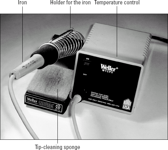
Figure 2-1. A soldering station: iron, temperature control, holder for the iron, and tip-cleaning sponge.
Warning
What about soldering guns? Don't use them for electronics! Even a 100-watt soldering gun applies too much heat. These are intended for heavy wiring jobs and large connectors. If you try to use a soldering gun on a PC board, you'll quickly overheat and ruin the board's thin copper cladding along with the components you're trying to solder.
Be sure you can use different tips on the iron you buy because there are several types of tips that you'll find useful. Most irons come with a 1/16" or ⅛" screwdriver tip. For regular electronics, you should have the following:
A fine-point conical tip for small components and surface-mount soldering
A 1/16" screwdriver tip for regular jobs
A ⅛" screwdriver tip for heavier soldering
The solder you need to use for electronics work is rosin-core flux, 60/40 or 63/37 alloy. (The two numbers in the fraction refer to the percentages of lead and tin, respectively.) Any thickness from 0.025″ to 0.035″ is fine for general use. You may want to have some thicker 0.050" for soldering large connectors and some 0.020″ for delicate connections and surface-mount components. Purchase your solder from electronic suppliers; the type that's available from hardware and plumbing stores is too heavy for electronics.
Note
Flux: A chemical that cleans metal surfaces to be joined by soldering or brazing. Rosin-core solder wire is actually like a tube made of solder that contains the rosin-type flux. Flux melts at a lower temperature than the solder, so it runs out of the solder strand and onto the metal surfaces before the solder melts. This prepares the surfaces and helps make a secure joint. The flux then boils away as smoke — that's what you smell when you're soldering. Flux can also be purchased separately as a liquid or paste for special soldering jobs.
The following task shows the basics of soldering a component lead to a circuit board. This is the most common soldering operation for most circuitbuilders. Once you're skilled at this operation, it's easy to solder other types of connections.
Before beginning, double-check: You DO have a pair of safety glasses or goggles, don't you? Solder can splash or splatter surprising distances. Protect your eyes! If you burn yourself with the soldering iron, the best thing to do is immediately run cold water over the burned area. A few minutes in cold water (or with an ice cube applied) will prevent most blisters. One more warning — DON'T grab for the soldering iron if you accidentally yank the cord or drop it. Chances are pretty good you'll grab something hot and that will result in a real burn. Just let the iron fall on the floor and pick it up. It's not hot enough to instantly start a fire, but it is hot enough to burn you!
Turn on the iron or soldering station and wet the sponge for cleaning tips. You don't need the sponge to be sopping wet, just a little beyond damp. An empty drinking-water bottle makes a good sponge wetter.

When the iron is hot (solder melts almost instantly when you touch it to the tip), wipe both sides of the tip across the wet sponge. Do this every time you take the iron out of the holder to keep it clean. If you are soldering many joints, clean the tip every few joints to prevent a residue of oxide and flux from building up.
Note
Tinning: The coating of a metal surface with solder. The tin in the coating stays shiny and does not oxidize; solder will readily wet it. (Component leads are tin-plated for that reason.) Modern soldering irons have tips with a tough iron coating that doesn't need to be tinned the way the big irons for plumbing work have to be. It's enough to keep the tip clean; it will self-tin as the iron is used. After heavy use, the iron coating will eventually wear through, exposing the copper underneath. When this happens, it is best to just replace the tip; at that point, the copper will rapidly degrade and pit.
Make sure the component lead and pad are both free of grease, insulation, oxide, or any liquids. The metal surfaces should be bright and shiny.

Apply the tip to BOTH the lead and the pad. The easiest way to do this is to lay the slanting surface of the tip directly against the pad and press the side of the tip against the lead coming through the hole.
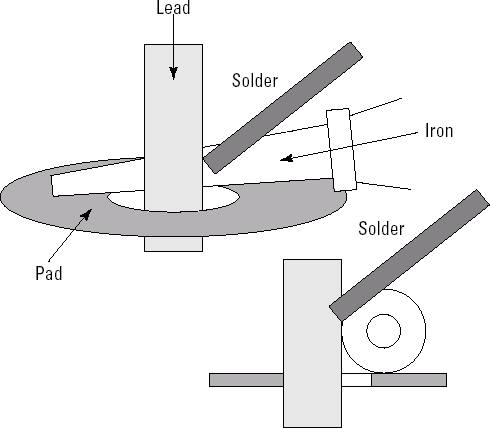
Apply the solder at the junction of iron, lead, and pad. It should melt almost immediately.
When the solder melts, feed a small amount onto the joint, then pull the solder strand away. You should use no more than 1/4" of the strand on most joints.

Leave the iron on the joint for no more than 1-2 seconds. The solder should flow around the lead, forming a convex fillet (solder fills the joint between the pad and lead) that completely encircles the lead and flows completely over the pad.
Remove the iron and let the joint cool. The fillet should be shiny. Inspect the pad to be sure excess solder hasn't flowed to adjacent leads or pads. You are looking for three types of defects:
Dull, rough, or pitted surface. This indicates that the solder was overheated or not heated enough. Sometimes adding a small additional amount of solder will allow the fillet to form properly — just re-melt the solder and add a small amount from the strand.
The joint is blobby or the solder pulls away from a lead or pad. Either the lead or pad was not sufficiently heated or its surface was not clean. Remove the solder as described below and re-solder the connection.
Lead moves when pulled or bent. This can also be an indication of the previous problem or the lead may have been moved before the solder solidified. Reheat the joint and try again — you may have to add a bit more solder.
If you prefer detailed step-by-step instructions, there are a number of "learn-to-solder" soldering kits. Two of the more popular are these:
Elenco AK100 (
www.pololu.com/products/elenco/0321). This kit even includes the soldering iron and a pair of wire cutters! (You'll want a better iron for long-term use, but this one is fine for beginners.)Chaney Electronics C6880 (
www.chaneyelectronics.com/products/learn-to-solder/c6880.htm). Four small PC board kits are provided in this package. You will have to provide your own soldering iron.
To "undo" a solder joint and remove the component lead takes a couple of steps. First, you remove excess solder with a solder sucker. This is a spring-loaded tool whose tip is placed against the solder joint. You melt the old solder with the soldering iron, put the tip of the solder sucker next to the bead of melted solder, and then release the spring in the tool: A piston retracts rapidly inside the solder sucker's tip, "inhaling" the molten solder into the tool. You may have to repeat this action a couple of times to get the bulk of the solder out. (Go to www.action-electronics.com/desolder.htm for a look at these interesting tools.)
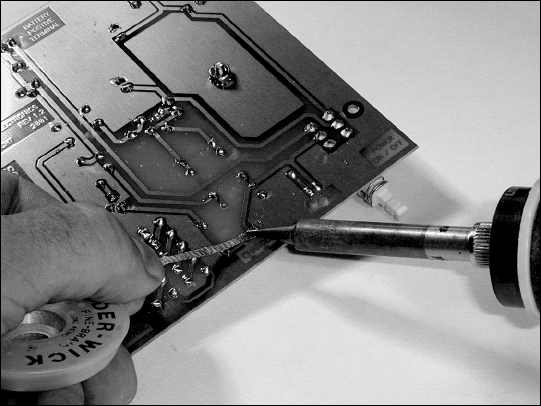
Since a solder sucker usually can't remove every bit of solder from a hole in a PC board, the next step is to use desoldering braid. The braid (also called wick) is made of fine copper wire impregnated with solder flux (that's what makes it sticky). When you press this wire onto a soldered connection with a soldering iron (as seen in Figure 2-2), the heat melts the flux, and then melts the solder; capillary action draws the molten solder up into the braid and away from the lead and the hole. Then you can use needle-nose pliers to wiggle the lead a bit, breaking whatever tiny bits of solder remain, after which you can remove the lead.
Once upon a time, schematics were hand-drawn by skilled drafters on large sheets of vellum drawing paper, reproduced on ammonia-fuming blue-line diazo paper, and laid out flat in special cabinets. Today, most schematics are entered into a computer, kept as files, and transferred at the speed of information around the Internet.
Warning
Just because a computer program was used to make a schematic doesn't mean that it's correct – or even that it makes sense! Computers are happy if all the lines connect and fit on a page, but the human reader needs more. Before beginning a project with a schematic from an unknown source, you should make sure that it makes sense. Check the Web site or later issues of the magazine to see if there are any corrections.
A schematic diagram has three purposes:
Serves as a symbolic connection diagram (not a construction diagram)
Describes the circuit's design
Helps with troubleshooting
Think of the schematic as a roadmap to your circuit. By using standard symbols that are the equivalent of an electrical alphabet, schematics store complex design information in a form that can be read by others who know the symbols. The connections between the symbols, when arranged clearly, create small groups of symbols describing specific functions, such as an amplifier, a filter, or a control circuit. To an experienced reader of schematics, these groupings make it clear how the circuit's many parts work together. This also allows someone trying to improve or troubleshoot the circuit to understand how the circuit is supposed to work.
Before tackling a schematic, you should become familiar with the symbols and conventions used to draw schematics. A good set of symbols can be found online at www.kpsec.freeuk.com/symbol.htm. You can download the symbols as graphics files from this page, as well.
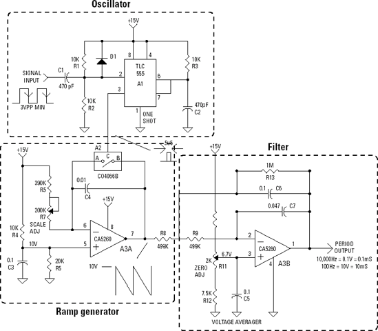
Let's say you're trying to decipher a new schematic, such as the period-to-voltage converter shown in the following figures. Try to break the schematic into sections; this will help the individual details make sense. It works for any kind of circuit, provided the schematic has been drawn in a reasonably organized way.
Don't be concerned that the circuit in this task is complicated. The circuit is presented only as an example of how to break up a busy schematic into bite-sized sections that you can analyze individually. A comprehensive treatment of reading and drawing schematics is beyond the scope of this book.
Make a few photocopies of the schematic. Writing notes, labeling parts and pieces, and outlining sections on the schematic, especially in different colors (red for power, green for signals, blue for control signals, and so on), helps keep track of all the functions.
Scan the entire schematic and try to identify the major functions and components. Draw lines around the parts of the circuit that perform related functions. If necessary, make your own block diagram. Browse the entire schematic, identifying the major functions and important components. Draw lines around the sections that have a common function, such as the power supply, an output amplifier, filters, sensors, and so on.
When you have a good working grasp of what the circuit does and how the schematic is organized, start focusing on the details. If you need to, make more copies of the schematic to keep everything straight. Remember that every schematic is different, so the following steps only show an example of how reading a schematic works.

For each group, identify input and output signals for each and where they make connections in the circuit.

Trace the flow of important signals through the schematic.
Identify and label the control signals and the internal connections for major functions and components.


Some schematics include ICs that have multiple symbols, such as a quad NAND gate or dual op-amp, note where each part is located on the schematic. Identify any unfamiliar symbols and read any notes or legends on the drawing.
From here, you can dig in to understand the circuitry in each section. You may not understand every component's purpose right away, but try to grasp the general operation of each section. When you're finished, you'll have a pretty good feel for how the entire circuit is put together and how signals flow around the schematic.
Here are some additional resources for getting a handle on schematics:
Beginner's Guide to Reading Schematics by Traister and Lisk.
Electronics For Dummies by McComb and Boysen (Wiley Publishing, Inc.).
"How to Read Schematics" an online tutorial at
www.best-microcontroller-projects.com/how-to-read-schematics.html."How to Read A Schematic Diagram" a downloadable article at
www.arrl.org/tis/info/pdf/8402019.pdf.